


rlwhitt
-
Posts
161 -
Joined
-
Last visited
Content Type
Profiles
Forums
Gallery
Events
Posts posted by rlwhitt
-
-
@Tomculb, hopefully not a highJack, perhaps this question benefits Old Navy as well. Have been reading your log of this kit and you mentioned pre-made eyebolts. Do you recall where you got them?
Thanks!
-
This is great - I just received this kit and am planning to get started as soon as I finish the last bit of the Longboat. Good to see a contemporary build - good luck! And feel free to find all the trouble spots before I stumble onto them. 😀
-
Hi All,
I was eying the Essex of Model Shipways and like the look of the subject and finished model. However, noticing the paucity of build logs I searched a little deeper and keep seeing the mention of "issues" that may or may not have been resolved around 2015, but I have not found much in the way of specifics. Does anyone have any idea the nature and severity of these issues? I think I am reasonably capable of adapting to minor fit issues and the like but if it's something fundamental that will throw the whole thing off, I don't want to waste months of my time.
Edit: I should have mentioned that I'm aware of the mismatch of some of the hull lines with some of the plans and perhaps exact historical accuracy. I know that's important to many here, but at this stage it's not really my concern, as long as the thing can be built. I'm more concerned about something so badly designed that it causes major fit issues weeks down the road with other parts.
Thanks!
- Ryland Craze and mtaylor
-
 2
2
-
Windlass & Rudder
I decided to go ahead and place the photo-etched brass decorations now, while the hull is easy to handle. The instructions have you `doing it basically last, after all the masts/rigging are on. I think that's unwise, particularly for a clumsy one like me. These are very east to put on, but I had to cut a bit off the last one up at the bow, even though I was putting them VERY close together like the instructions say.
Now we build the windlass. A good bit of carving The square holes are a bit of a trick, it helps a lot if you have a small square file. You can get them almost square with an x-acto #11, but the file sure helps.
completed item, mounted with the handles in place. They are removeable so I set them aside for final assembly.
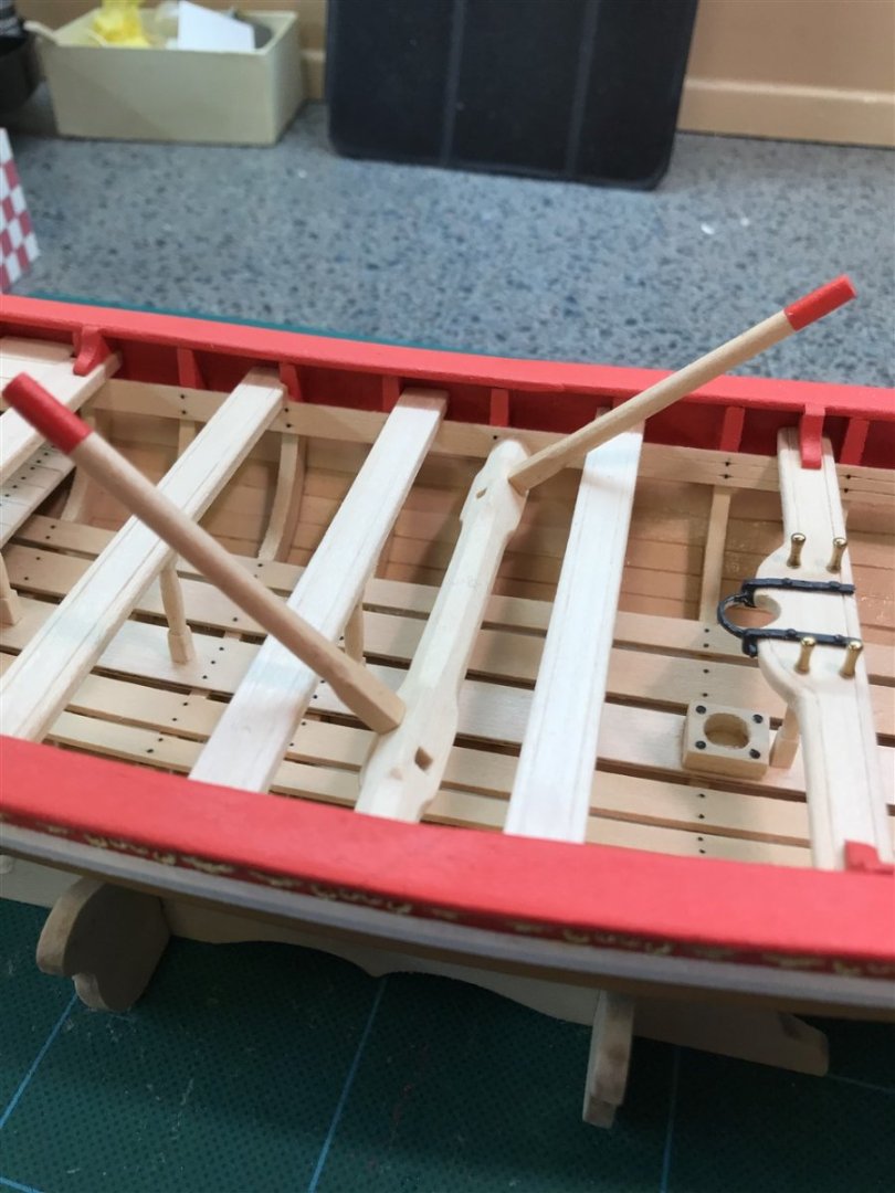
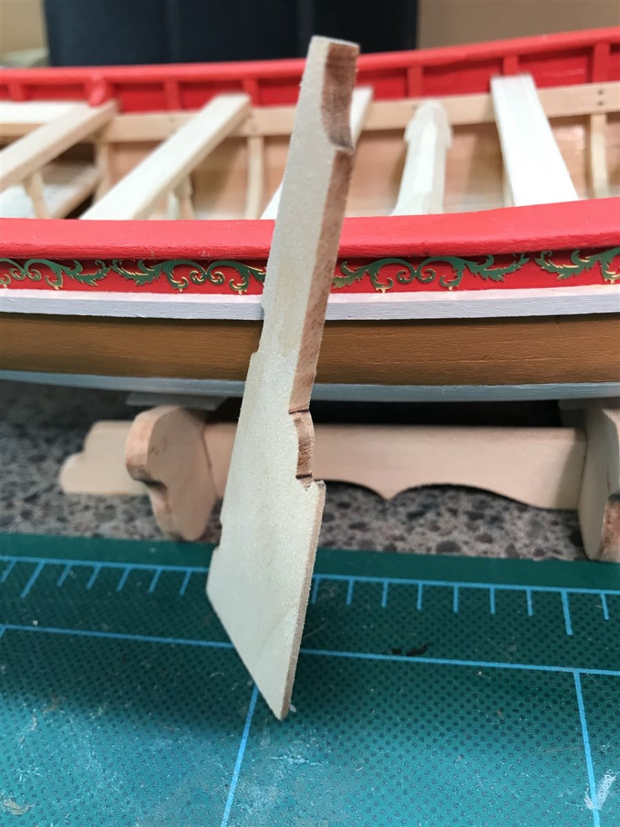
On to the rudder. Some more carving and shaping, getting the leading edge rounded and the trailing edge thin:

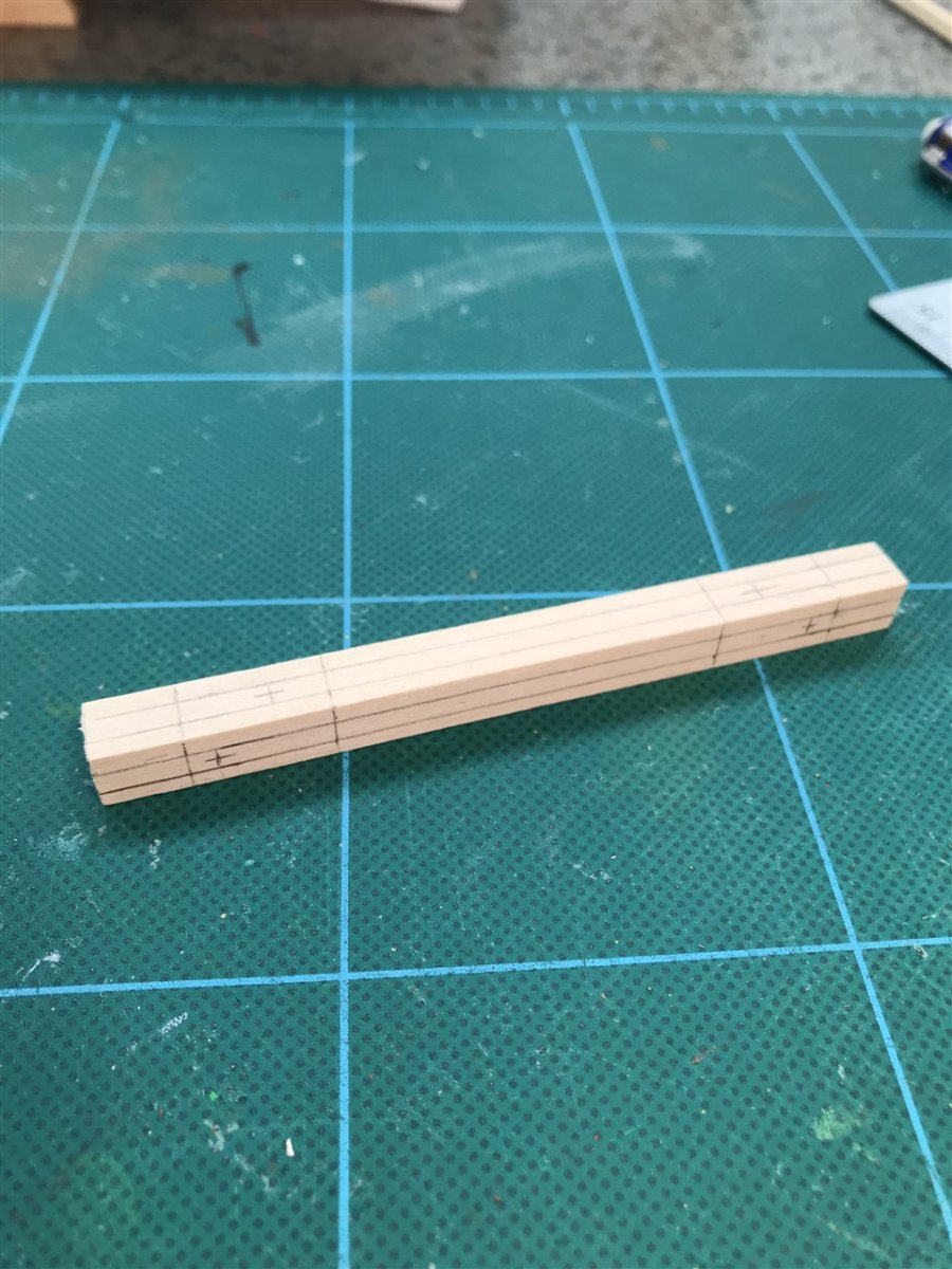
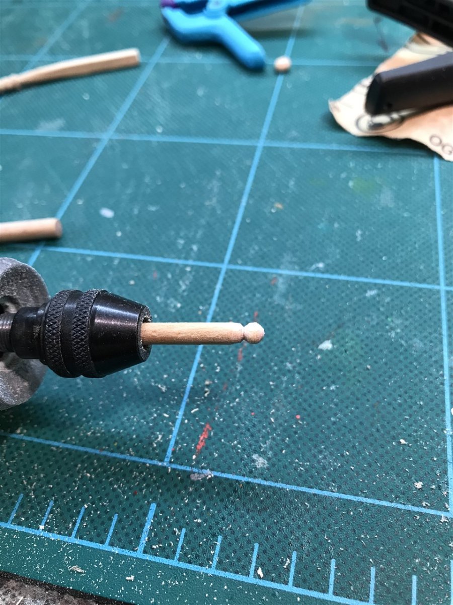
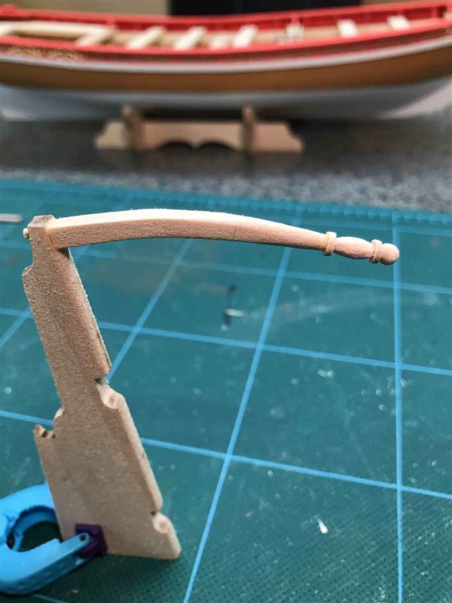
Then we need a tiller. Instructions have you bend a piece of 5/32" square, and carve the little handle and ball at the end. As you can see, mt attempt at this was very sub-optimal. So I took another stab, this time building it up from parts. Lower example shows 3 pieces of strip sotck glued together at an angle to form a rough curve which we will sand a bit later to smoot out. Then I turned a handle from some dowel in the Dremel and used my Screw Punch to make some disks from 1/32" scrap.
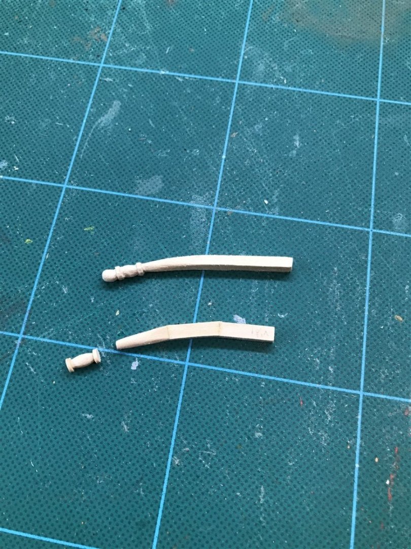
And then a ball for the end:

Assembled and sanded a bit

Finally, we paint it, along with the Britannia metal pintles and gudgeons, and then mount it. It's removable, so I'll lay that aside for protection as well for final assembly later.
- CiscoH, Prowler901, Ryland Craze and 3 others
-
6
-
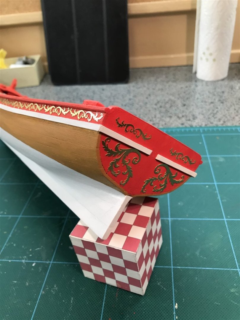
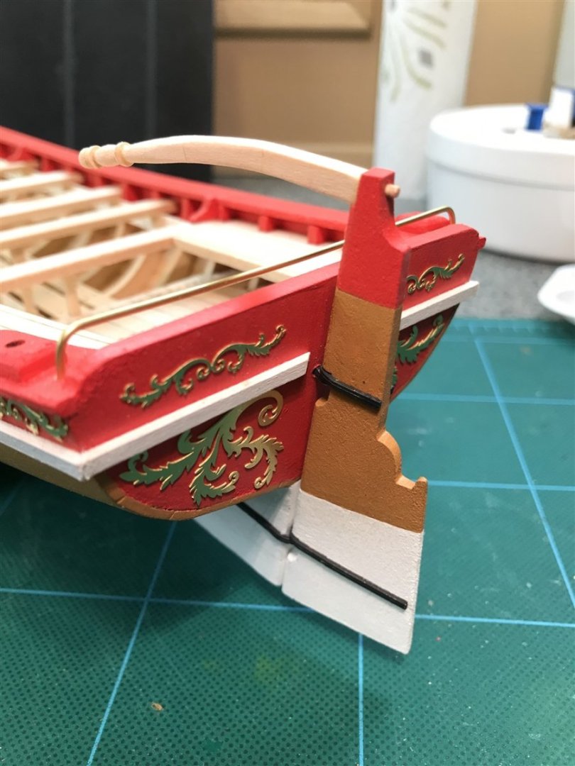
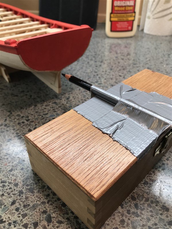
Cap Rail and Painting
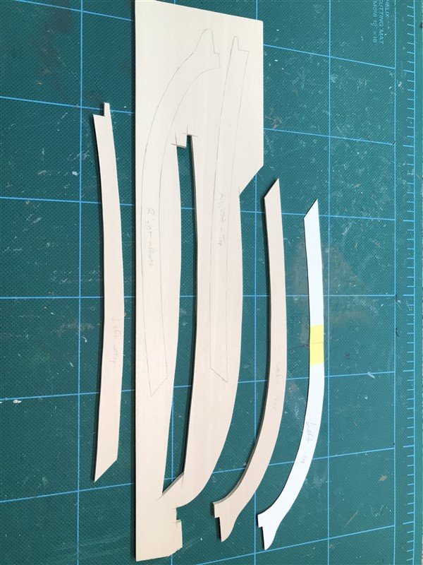
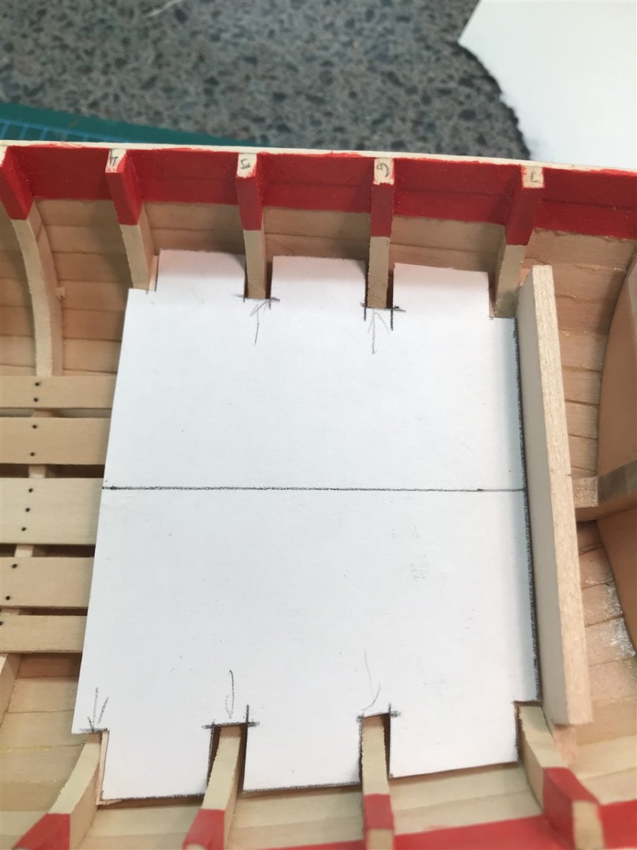
Next we use some card stock to trace an outline of the top plank and then add enough width to either side of the line for outside overhang plus enough to cover the tops of the frames inside (about 3/8" total). Trace the pattern onto the one piece of sheet stock in the kit and cut out
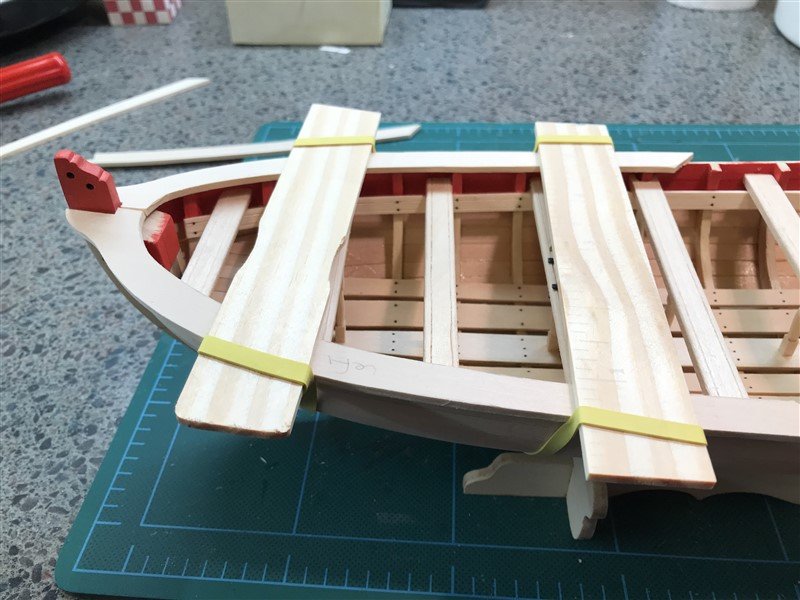
Glue and strap 'em down. Handy use of paint stir sticks.
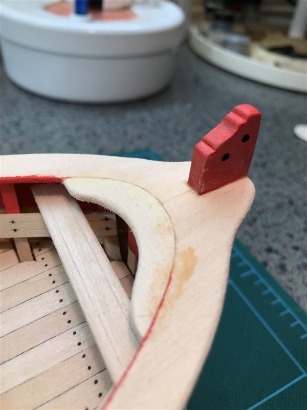
There's a laser cut part at the bow that did not fit my cut, so I made a new one out of scrap
Attached the gun mounts and transom knees, then painted it all red.
Now on to the external paint. First we draw our waterline, and I lucked out and my little wood x-acto box put the pencil in exactly the right place!
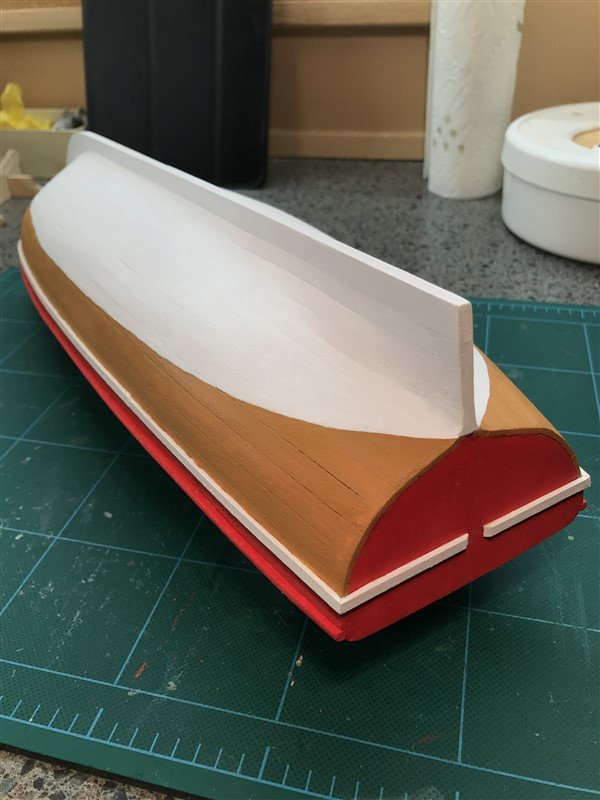
Finally, skipping ahead a bit to the more or less finished exterior. I did the Yellow Occre for above the waterline. Also seen is the rub rail (white). I deviated here a little. Kit supplied 1/8" square strip was supposed to be shaped half round with a tool in the photo-etched brass sheet, but it was the wrong size, for 1/16". So, out of luck there. I made my own shaper with x-acto blades, and it more or less worked but was hard to get a smooth shape. Plus they are very hard to bend. I just gave up on the idea and put on 1/16" x 1/8" - much easier.
- Ryland Craze, Ghost029, CiscoH and 3 others
-
6
-
9 hours ago, Ghost029 said:
Removing interior frames. Planking turned out better than I thought after filling and sanding. Great learning experience. Instructions state to now sand interior frames and install cap rail. I would think that I want to install floor planks and seats before the cap rail. I will go back through the directions again.
I would agree and am surprised it would recommend that order, especially since the seats sit a bit under the cap.
-
Thwarts and rear cockpit
Well, this stage presented several fit problems, as I'll show. But nothing serious.
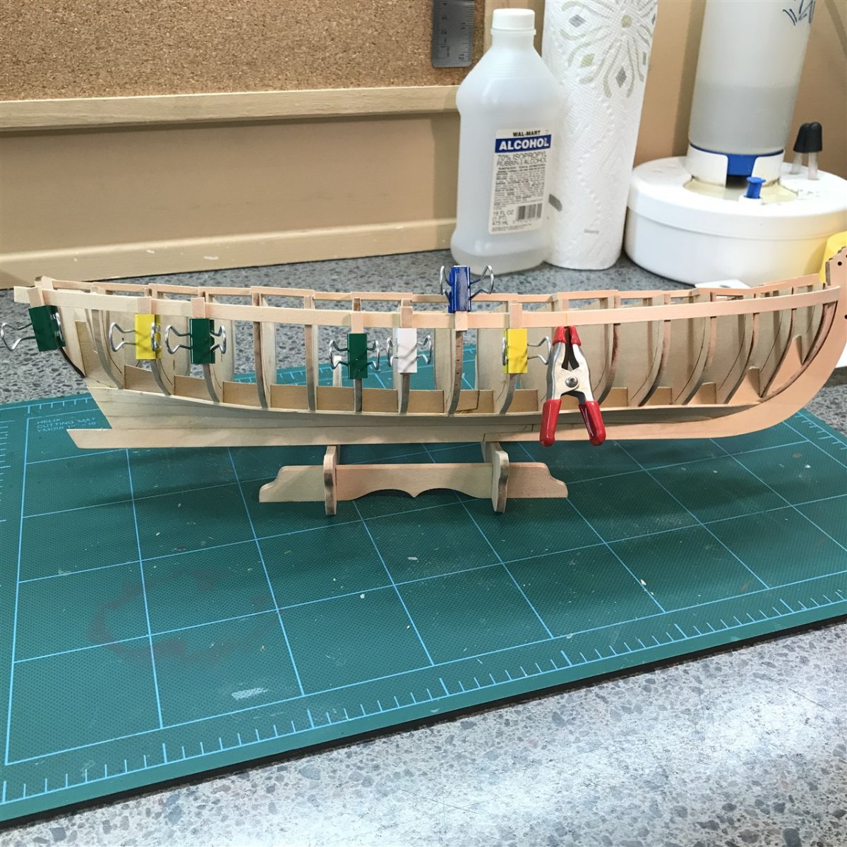
First up we have to use 1/4" strips on both sides for thwart risers. You have to do a fair bend here, but I did it dry without too much trouble. I clamped first, then used thin CA to attach, I scraped some paint off though before installing these as I don't trust any glue to stick very well to paint.
Then we create all the thwarts (seats). One thing I'm grateful for in this kit is that they provide plenty extra strip stock for the inevitable re-do, of which there were several here. Never could get the scoring of the decorative lines quite to my liking.
The first uh-oh came at the cockpit seats. The parts are provided in rough size/shape, but in the end for the decorative lines to match, the middle part is just too short. So I used the carrier sheet wood that was right next to the part to fashion a little shim part. It sort of actually looks like it was made that way:
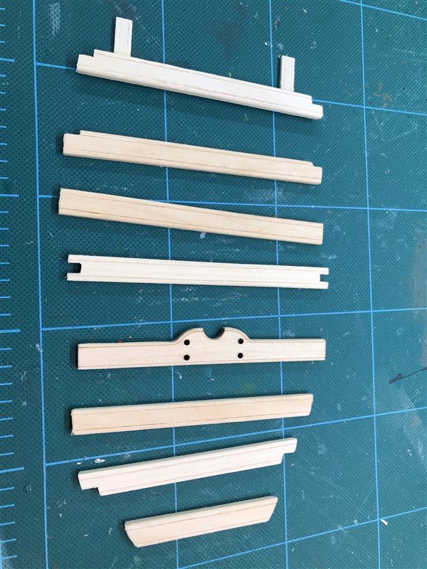
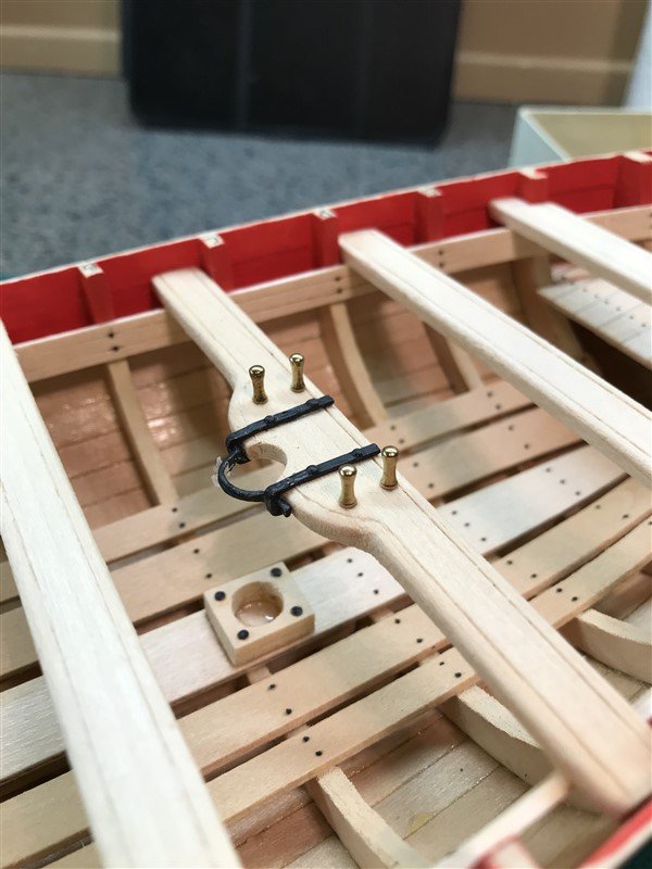
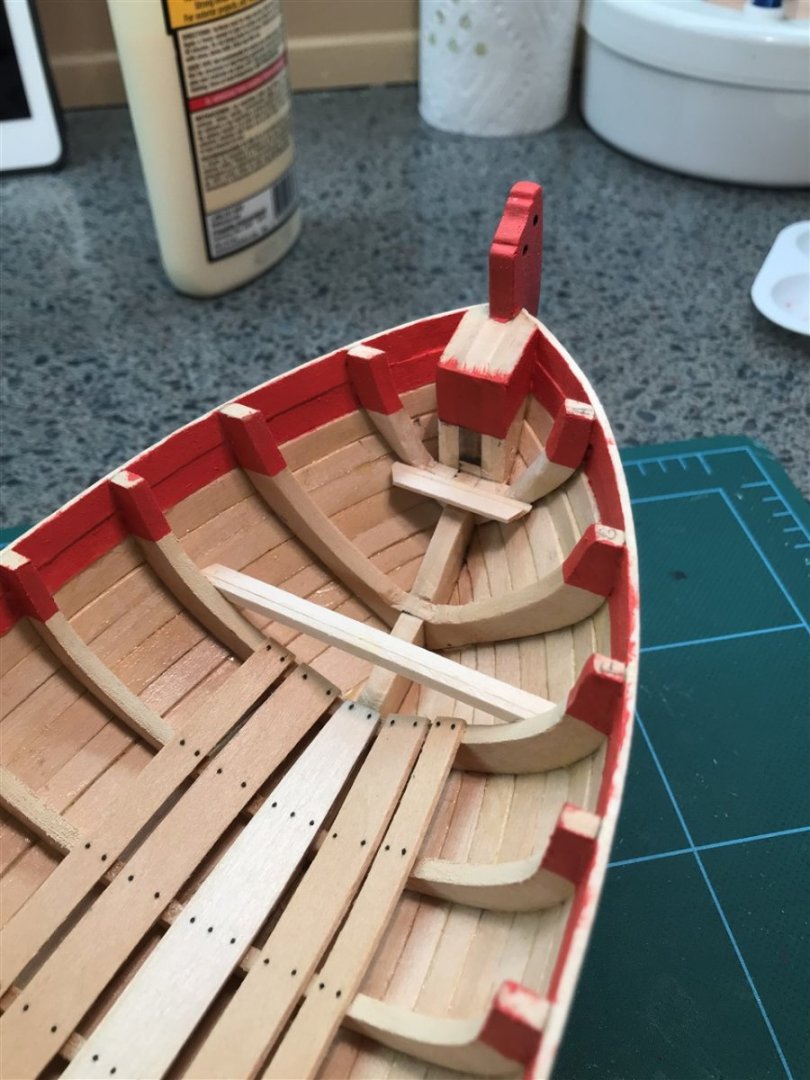
The next issue was the pre-made mast thwart, seen below. The semi-circle mast dowel cut out is too big, as are the belaying pin holes. Not sure what they were thinking here. I made a new one:
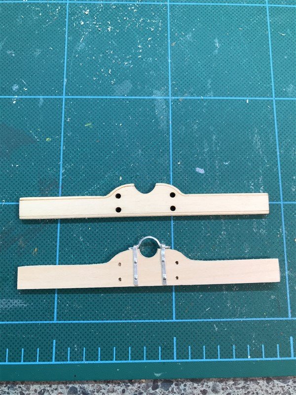
And installed it along with the mast foot. That's the next issue. The hole in the foot is also too big. I'm thinking that the mast must have been bigger when this was designed. Also, you are supposed to put nails in some corner holes, but by the time you sand off the char, the holes get exposed because they are so close to the edges. So, I replaced this with a homemade version as well.
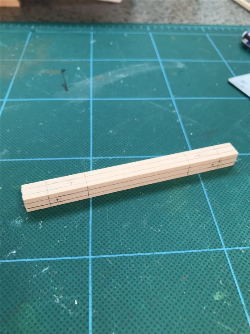
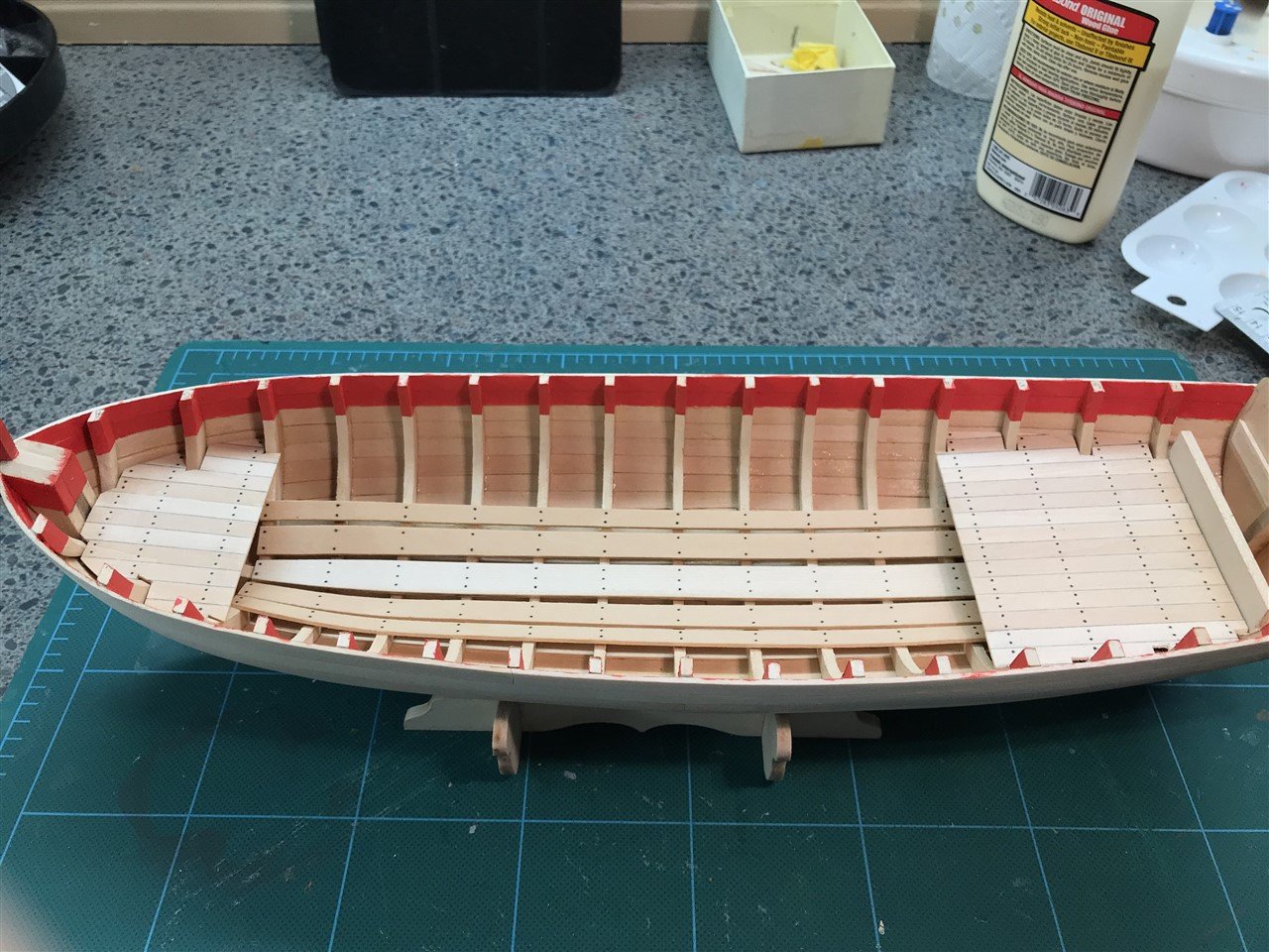
Finally for this section, we need support posts for the seats, carved out of 1/8" square stock.
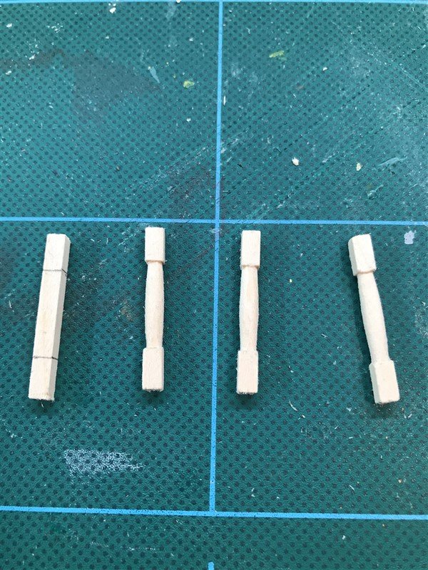
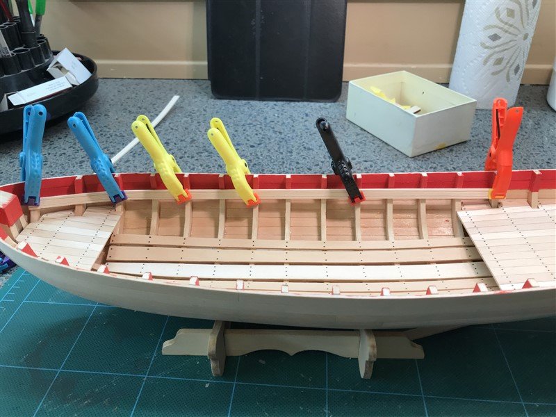
And here she is with all the seating in place. Next time we'll do rail cap and associated bits.
- Prowler901, Ryland Craze, Altduck and 2 others
-
5
-
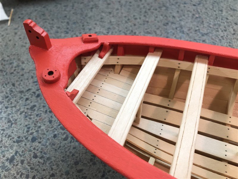
Interior Items - Floorboards and Platforms
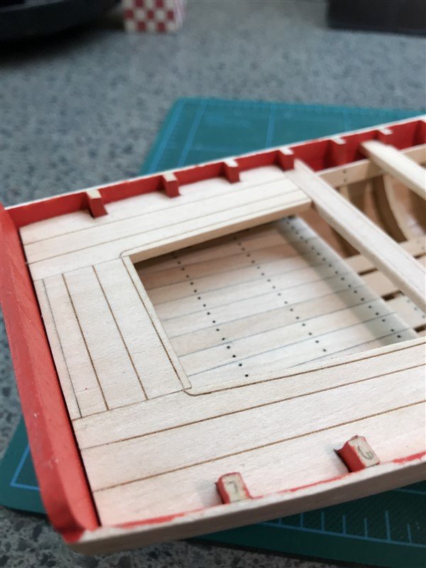
Time to start building the stuff people sit and stand on. First, painted the top 2 planks and the adjoining frame sections inside with bulwark red. Had to do this freehand so another go-slow place. Needed 2 coats.
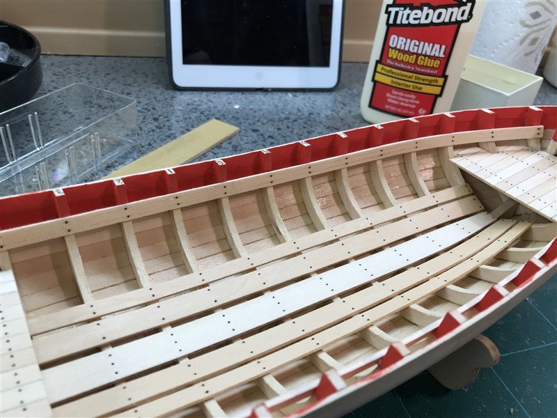
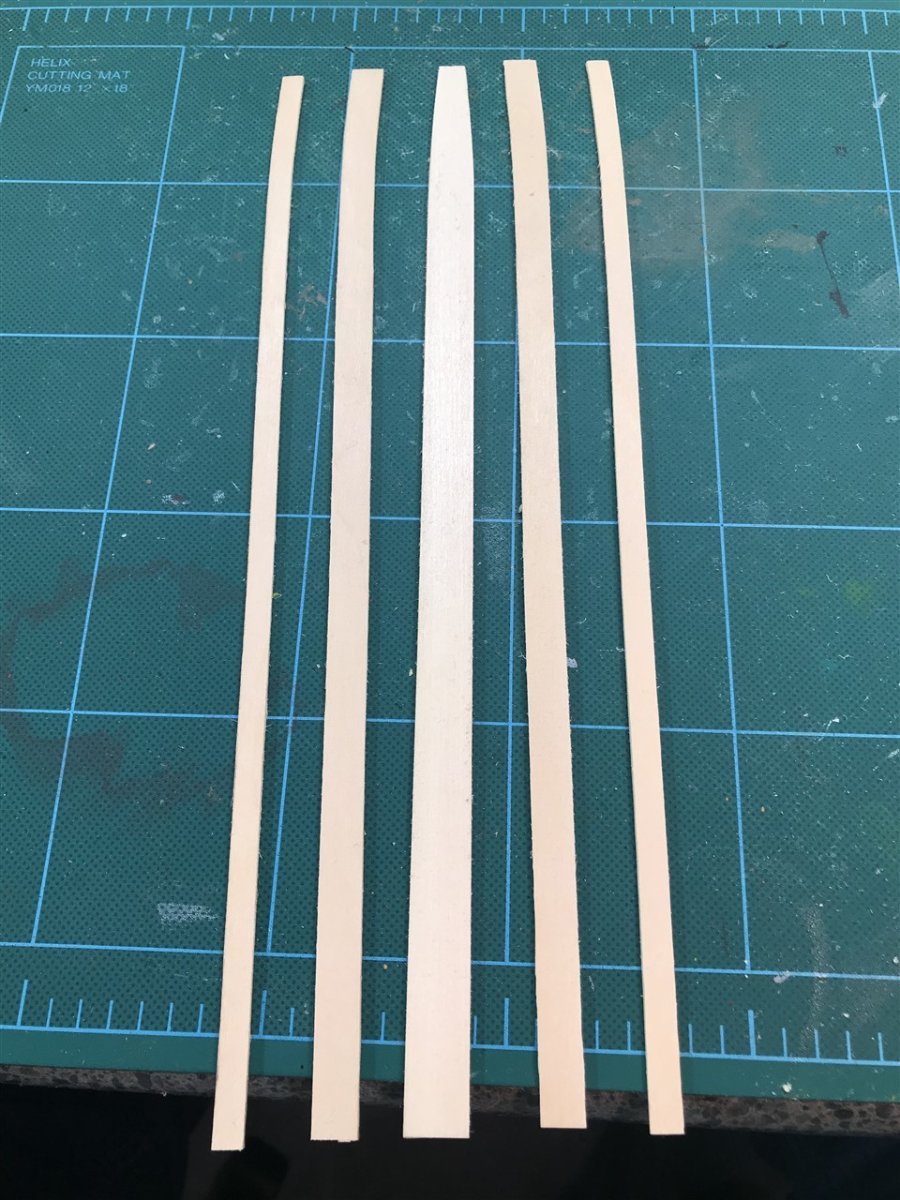
Next you cut and install the 5 floorboards. The center one has a curve in the forward 3", and the instructions have you edge bend 3/8" and 1/4" planks to match. Since I had plenty of 1/16" sheet stock left over from the spiled planking, I cheated and cut mine curved.

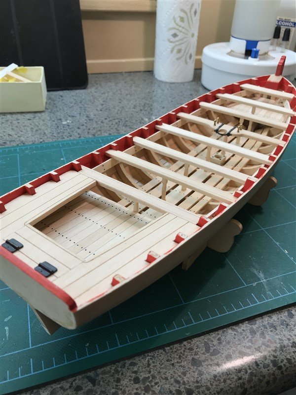
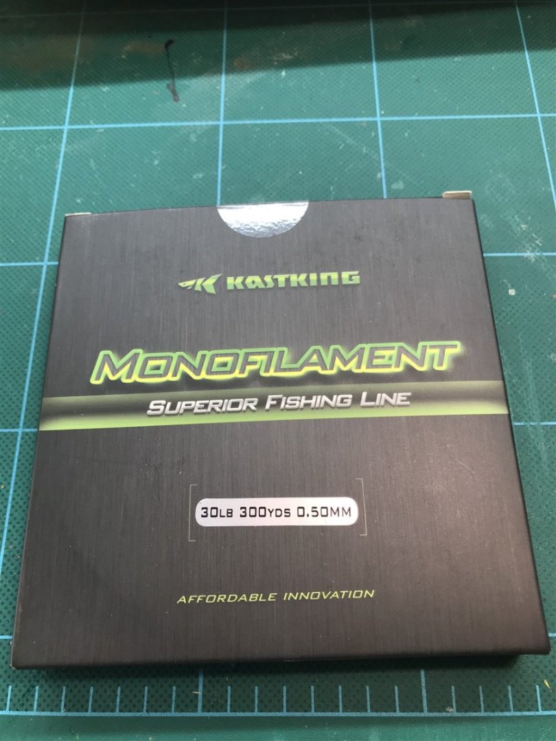
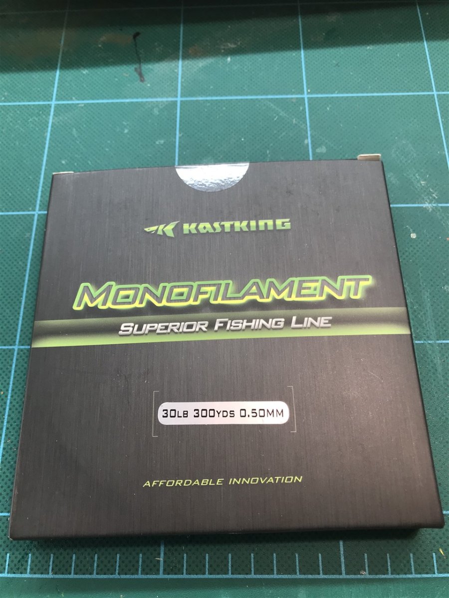
All along in the instructions, they are suggesting to make fake nails by poking a pentel pencil into the wood leaving a dark hole. I tried it, but never liked the results when it worked, and more often than not the lead would just keep getting pushed back into the pencil. Or breaking. So I'm stealing a technique from others here on the forums and using black monofilament to simulate nails. This is what I found on eBay. 30lb test might be a bit big for this model's scale, but 10lb is too small. 20 might be just right, but this is what I have, so....
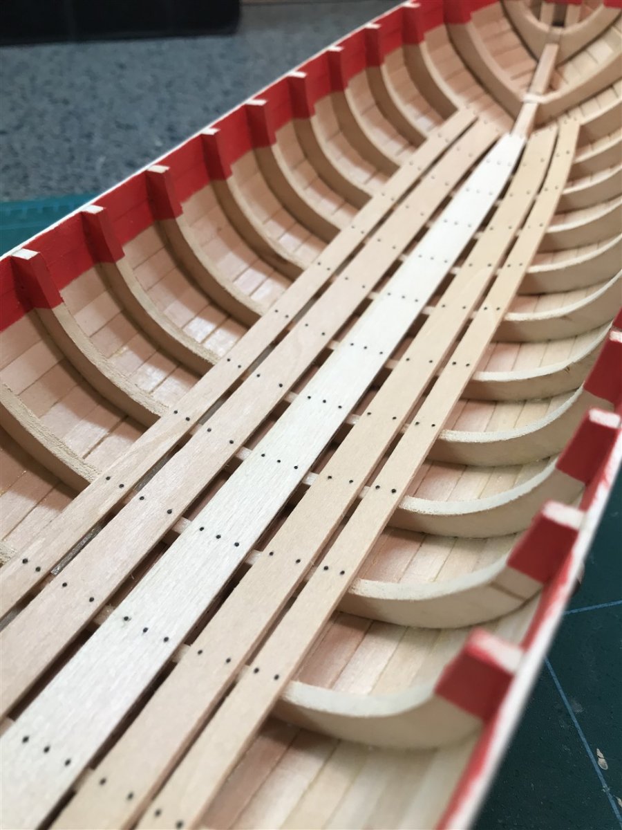
Drill tiny holes, cut bits of monofilament, dip the end in CA. After set, I snip off the excess with some tiny side cutting nippers and sand down the nubs.
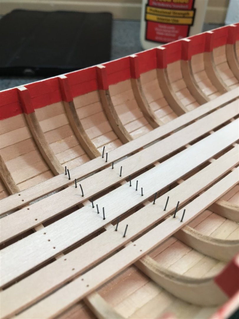
Finished floor boards:

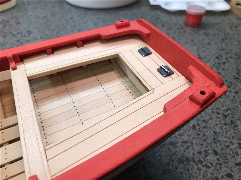
Next task is to install supports for stern locker, rear platform, and bow platform:
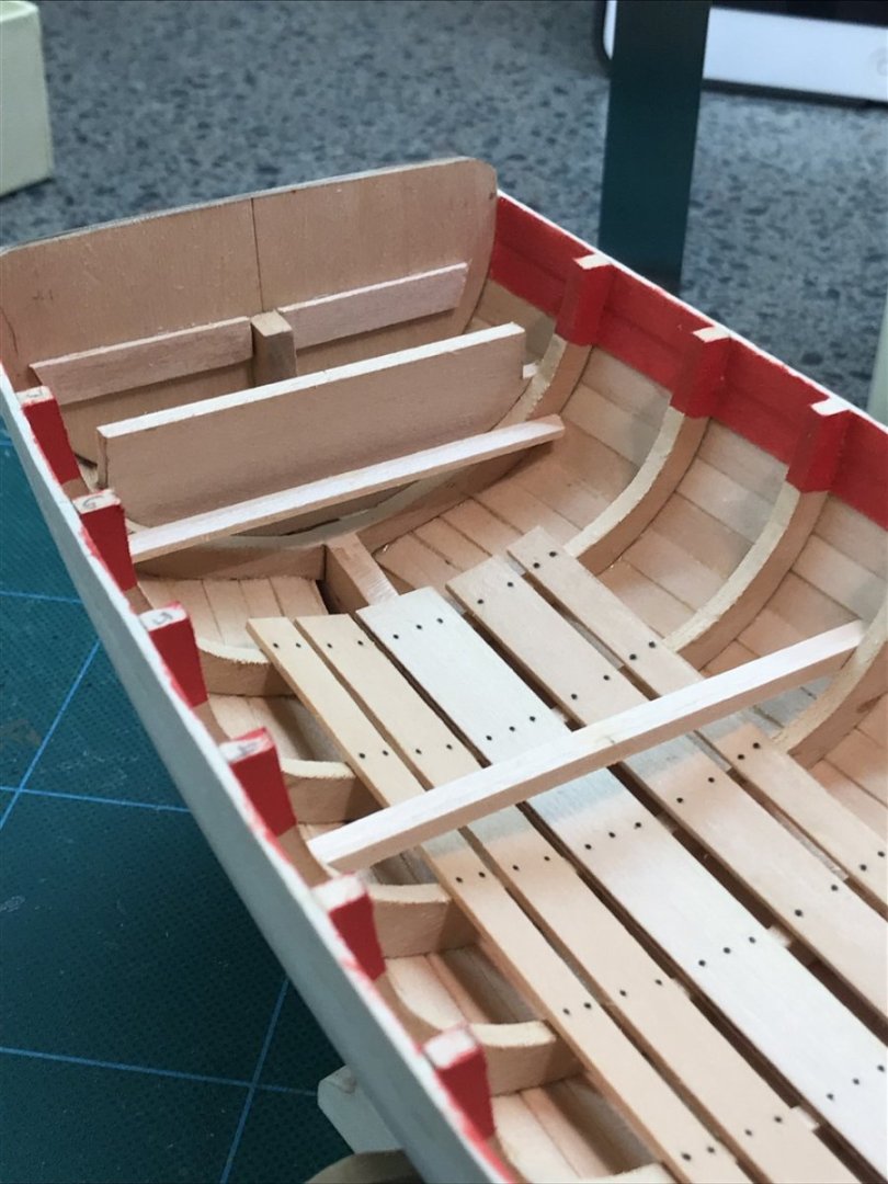
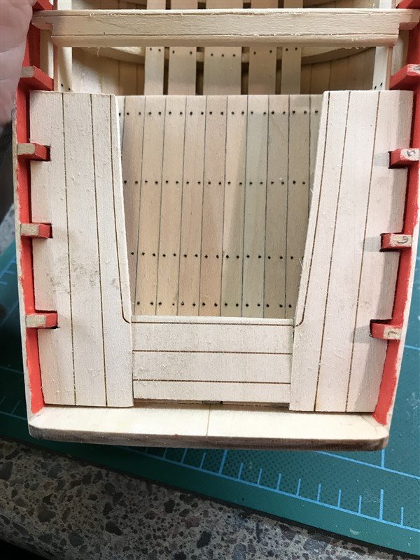
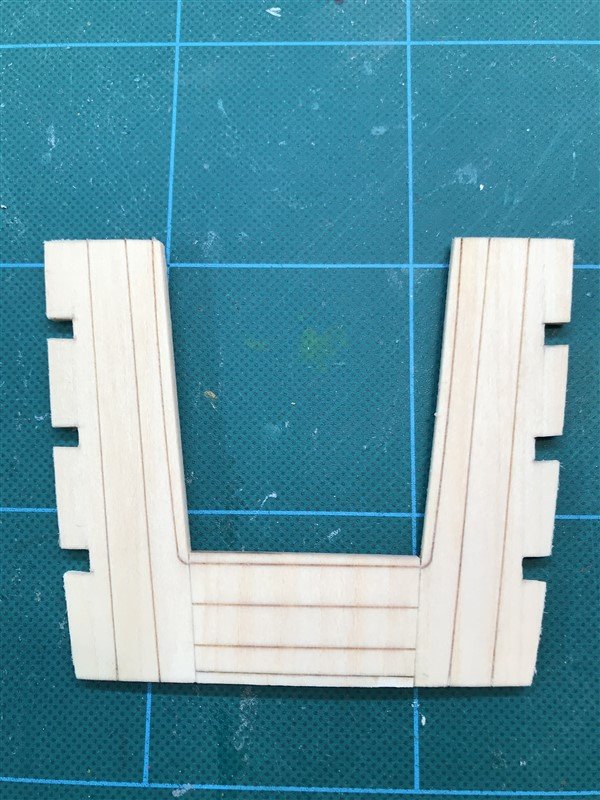
Then we have to create the platforms. This is a tricky bit. First you have to make a card stock template. Very much a trial and error process. Shown is my first iteration, which has some marks for how to make the next one a little better.

I neglected to take more pics of the process, but basically you edge-glue together a bunch of short 1/4" planks (leftover from planking), coloring the edges with pencil to simulate tar on the joints. Then you trace/cut from your cardboard template. Here are both platforms done and "nailed" down. I was not thrilled with my fit job on the rear one - too much space around the frames. Not sweating it too much though, as the sides will be under the stern seats so not visible anyway. The bow section is not great, but a bit better.
Next post we'll tackle the seating.
- Dfell, Ghost029, Prowler901 and 2 others
-
5
-
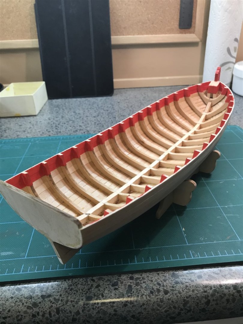
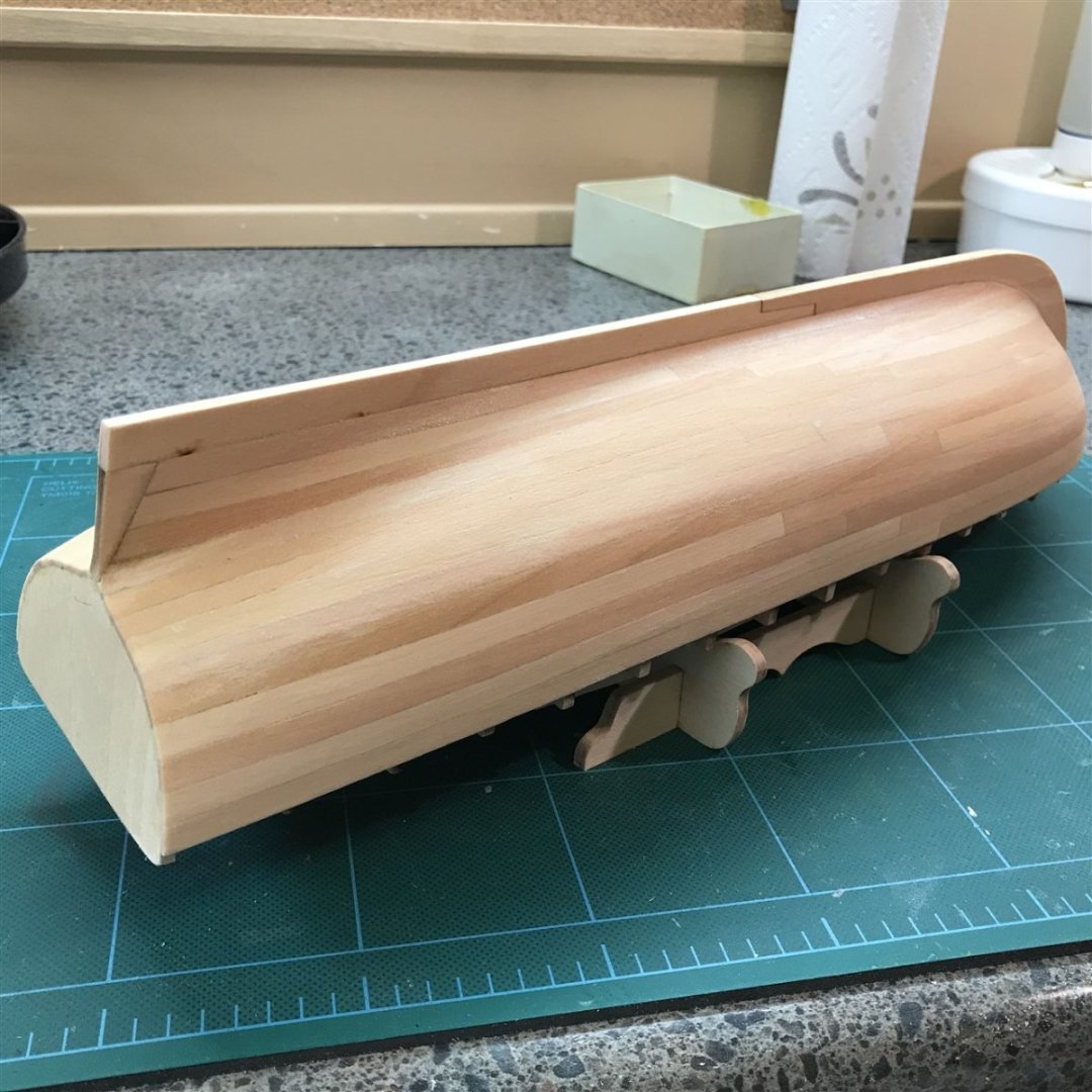
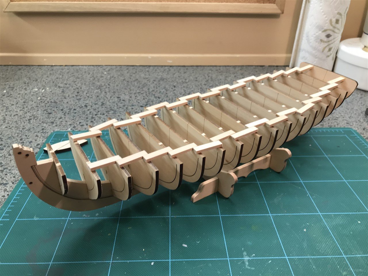
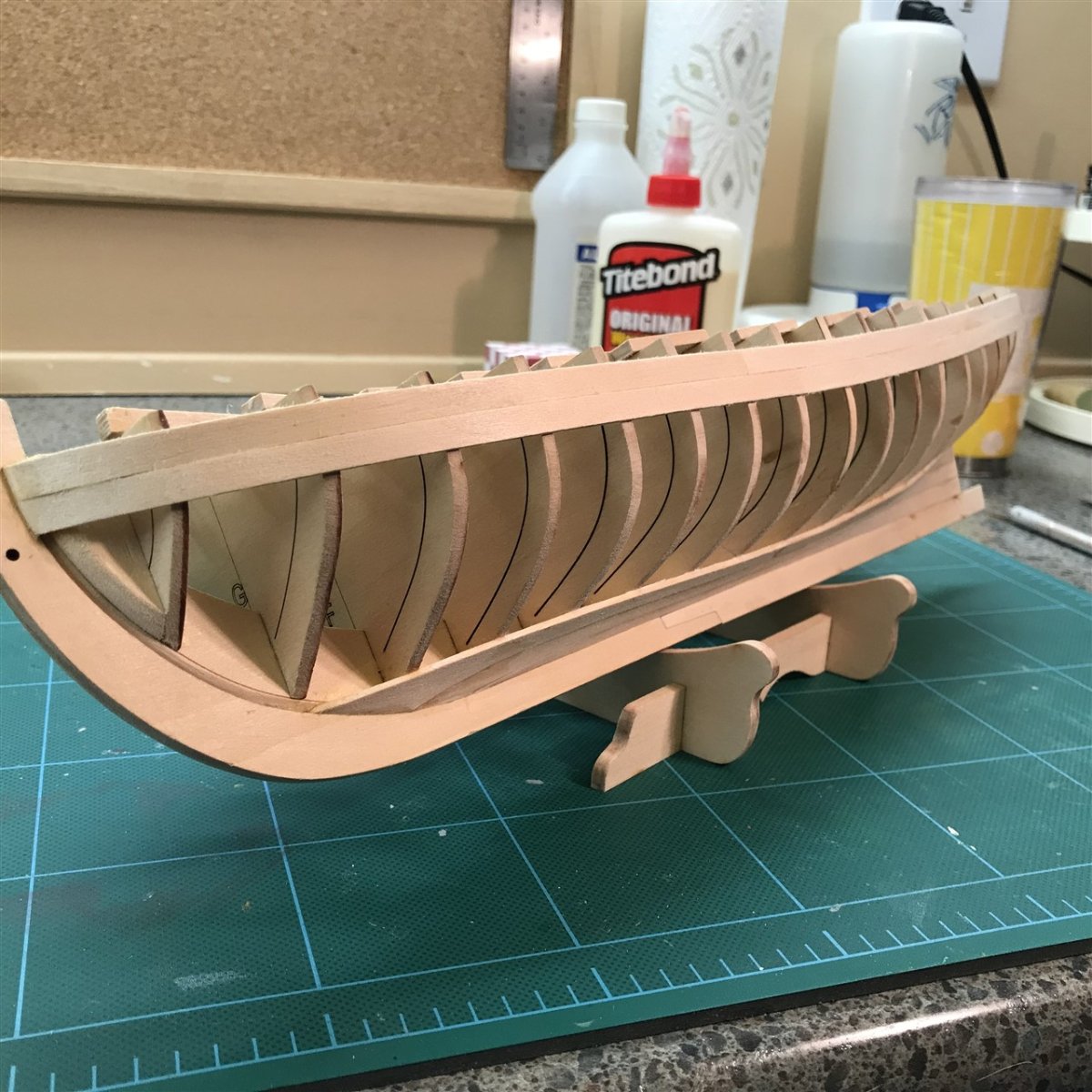
So next up is the destruction phase. We rip out the temporary support stuff, leaving just the frames. The first time sawing down the side and cracking out a bulkhead was a nervous moment, you just know the whole thing is going to break somewhere critical, but it works just fine. Leaving things looking a bit of a mess, but way more like a boat!
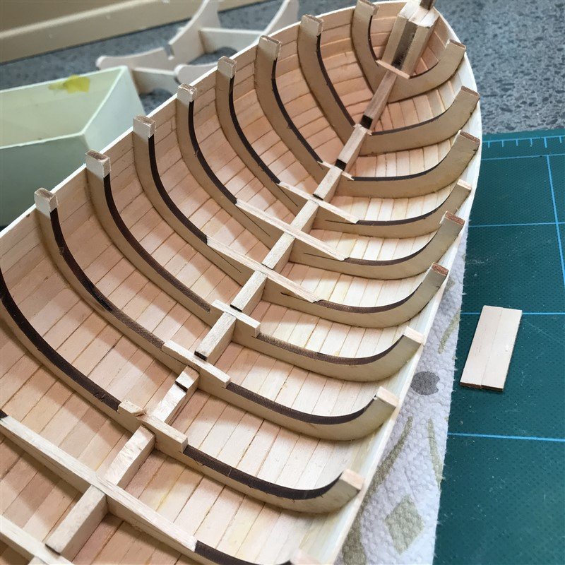
Next I rough cut the parts of the frames sitting above the shear plank. Not all the way, that will be done with a finer touch and some sand-stick work later.
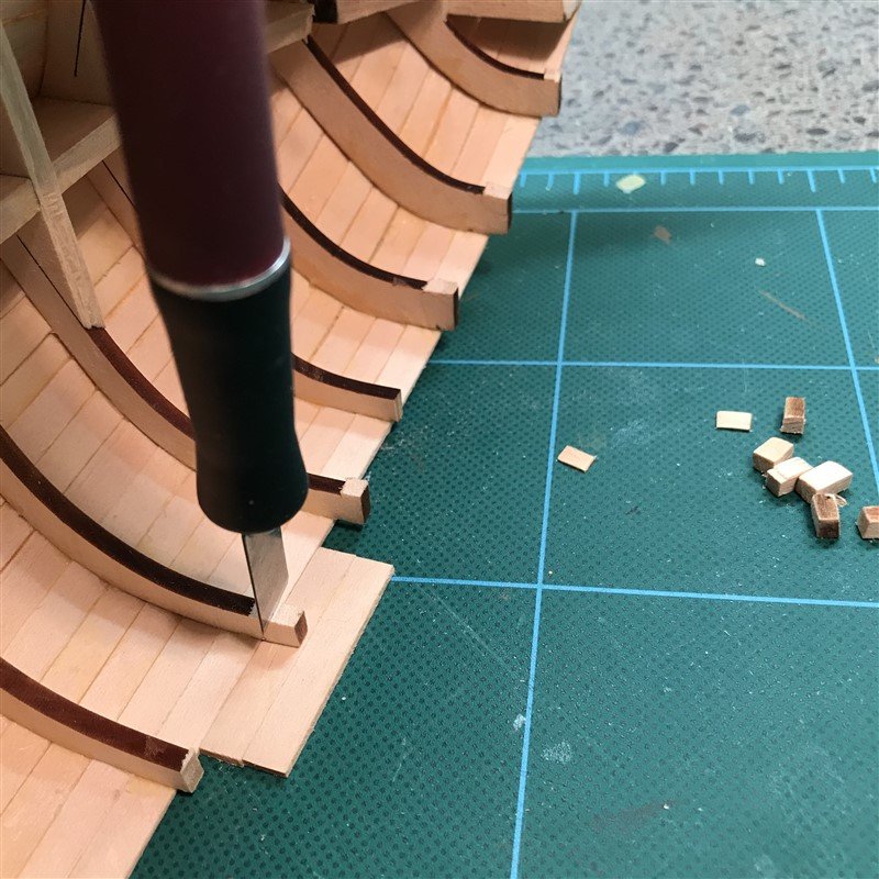
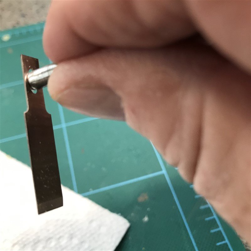
Next we have to take the frame bottoms and keelson down to the level of a frame thickness. LOT of tedious work here, go slow! Recommended to use an X-Acto chisel blade, but it's hard to get the handle down in there flat. I wanted something L-shaped so I could dig around horizontally more easily. I realized that there was a hole on the #18 blade and it fit a Dremel mandrel perfectly! So I've made myself a "finger adz". Made things much easier.
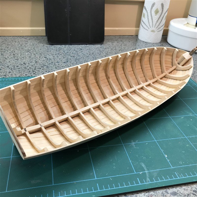
After much chopping and sanding, and fair number of salty words, finally a more acceptable looking result. Next step will be to begin adding stuff to the inside. Now the fun bits begin! I gotta say, sanding is about my least favorite bit of this - I'm glad it's mostly done.
- Paul Le Wol, Ghost029, Dfell and 3 others
-
6
-
Hi all, kind of a newbie question here that I did not find an answer to yet in search.
Assuming all water based products (minwax, titebond), is there any worry about long term bond quality of joints on wood already having a coat of conditioner? What about wood with a coat of poly? I’m going to assume for at least the poly it would prevent a very secure bond.
Thanks!
-
1 hour ago, CiscoH said:
that looks great!
Thanks!just had a look over at your AVS build (very nice BTW) and saw your pics of this longboat. I’m assuming it’s the same one but it looks like you did something different with shear plank scroll work - can you elaborate? The picture wasn’t quite clear enough to tell, but it looked like maybe you did some painting in there.
-
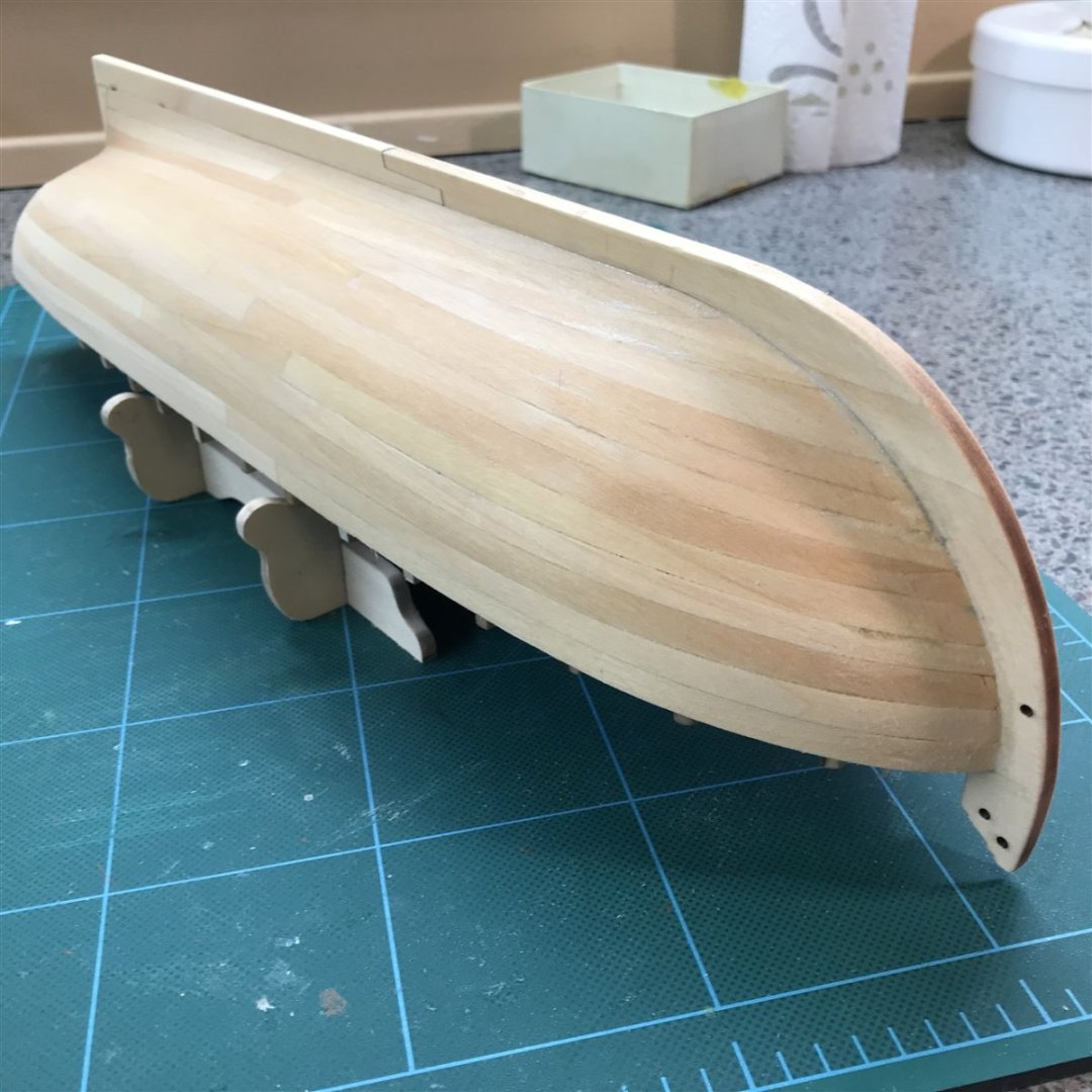
Planking is complete! Pretty pleased with it, particularly since I'll be painting the outside of the hull. I didn't end up using much of the supplied planking lumber except for the straighter runs in the aft half of some the rows, rather I cut the curved ones from sheet stock. It's cheap sanity in my opinion.
- zoran, Prowler901, Ryland Craze and 2 others
-
5
-
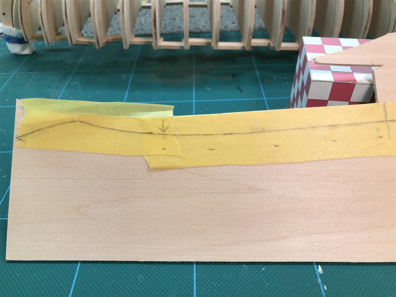
The planking begins! Garboard is stock 1/4" strip from the kit. I made the curve at the front a larger radius, per @Arthur Wayne recommendation on his build thread, and it did end up looking better. If you were "straight sticking" the adjoining plank it would also make the edge bend easier, but I spiled the next 2 rows in the bow end, so it didn't matter.
As for the spiling I've tried a couple of different methods but have settled on directly sticking tape down on the plank to be traced. I've tried scotch tape and it's nice that it's so transparent but it's hard to write on with anything but sharpie pens and such and they smear so bad. So, luckily I found this stuff at the hardware store - it's called "Frog Tape", and it's pretty easy to see marks through, and write on with a pencil. I like to use a dark artist pencil.
Transfer the tape to the wood sheet and make some tick marks for 1/4" width, leaving the front alone as I'm going to flare the front a bit wide.
And connect the dots using a curve, here I use a ships curve I found at the A-Word place.
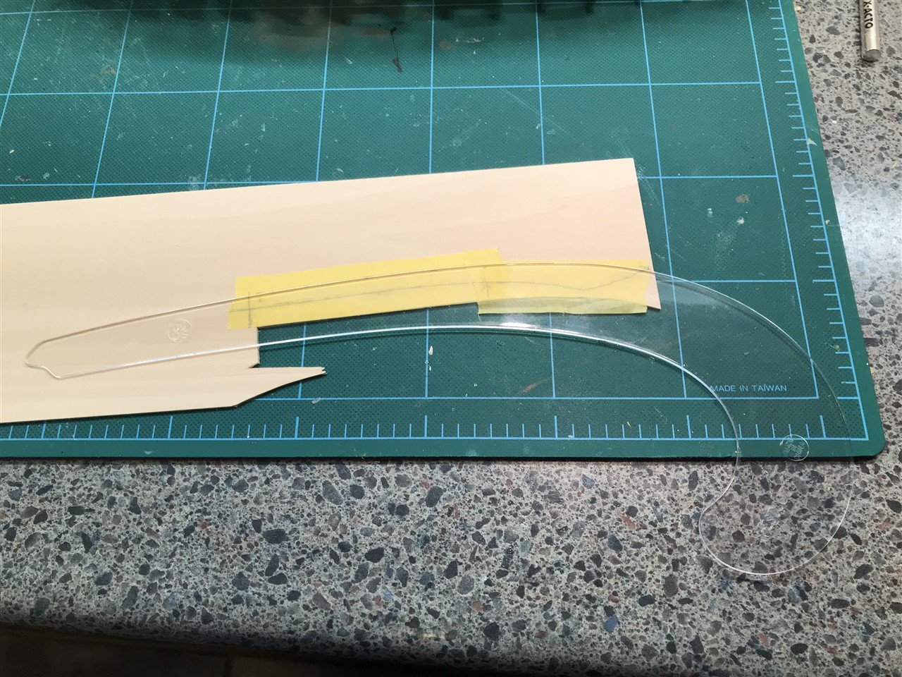
And the first 3 planks at the keel done.
Next they have you move up to the 2 planks at the top. The curve was gentle so I went ahead and used the supplied strip stock and edge bent.


Next post should complete the planking. They have you go back to the keel to get that last curvy bugger before finishing from the top down. They say it's the hardest one, and I have no doubt it would be with straight, edge bent sticks, but I'm going to spile those totally, and probably most all of the rest except maybe a few straight sticks on the aft half of the rows.
Rick
- Prowler901, Ryland Craze, CiscoH and 3 others
-
6
-
-
1 hour ago, Ghost029 said:
Pulling up a chair. Going to follow your build. I am building the same ship but in a smaller scale.
Yeah, just saw that. Will be interesting to see the 2 progress & how they compare. Looks like they are of the same basic design
-
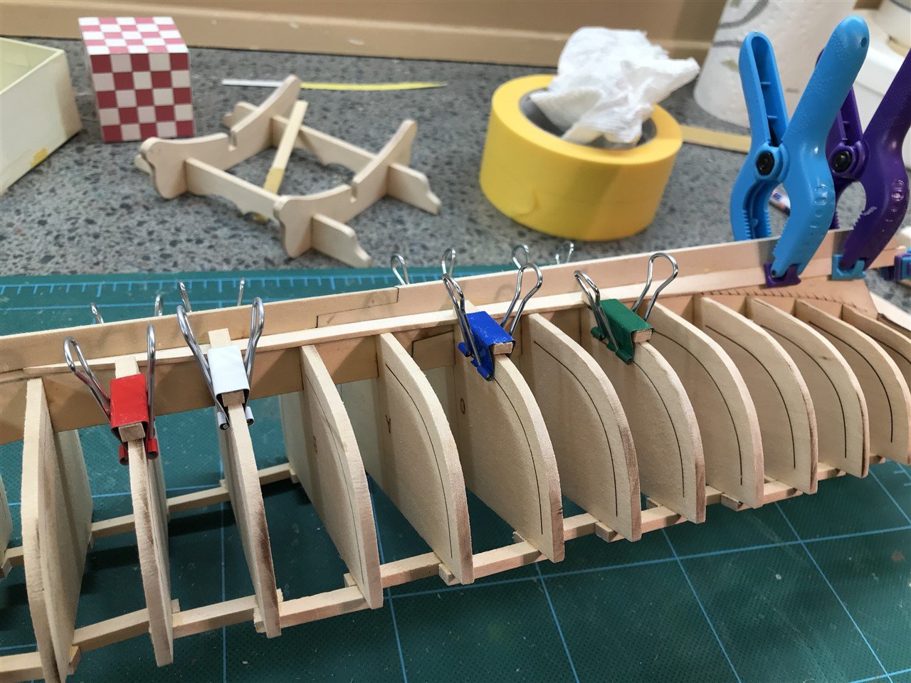
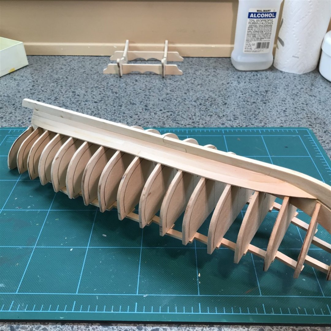
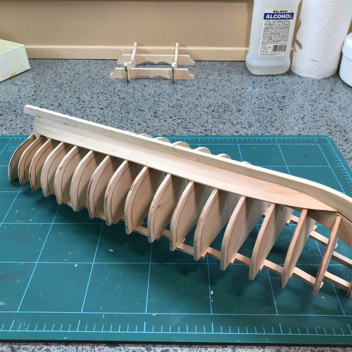
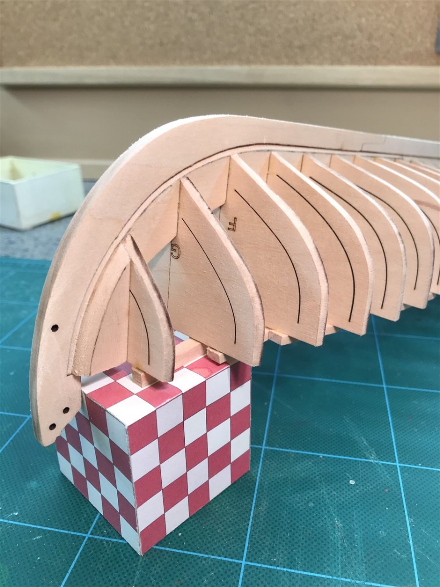
All bulkheads installed and braced. I used the 3 sticks provided for the "back brace" per the instructions, but followed the lead of others to make braces along the sides - much better support when sanding the frame edges fair.
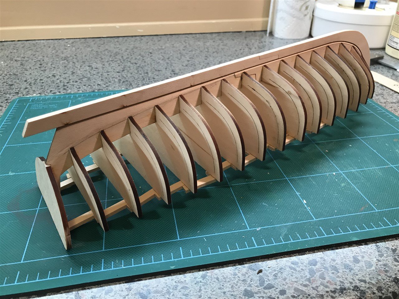
Bow filler bits and most of the fairing done. I'm going to spend a bit more time trying to get the best fairing job I can. On the half hull training I ended up with some little peaks and valleys because I didn't spend enough time on it.

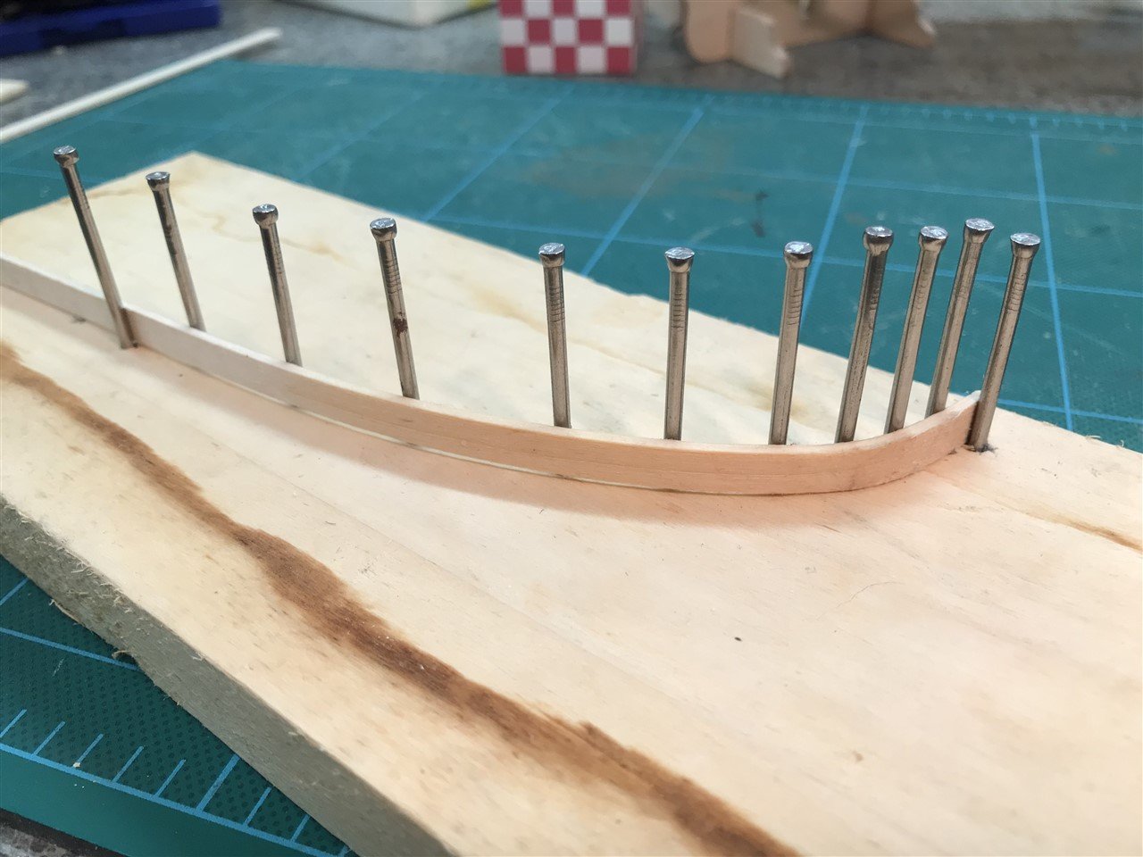
Next will be on to the planking. Been thinking a lot about that along with reading others' threads. I don't like the idea of edge bending per the instructions. I tried a couple of samples and was not thrilled with the process or results. Looks like I'll be spiling the curvy bits at the front.
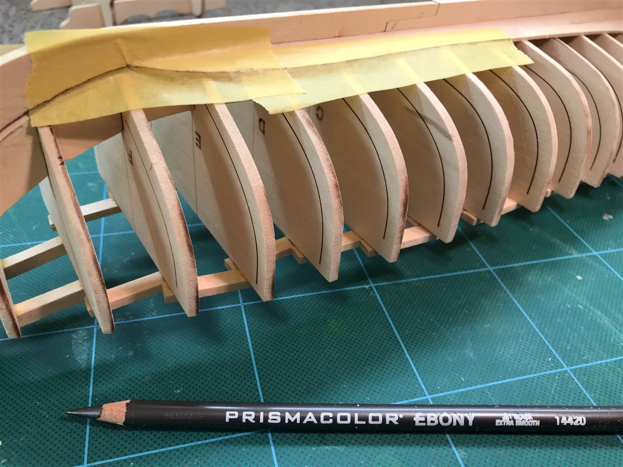
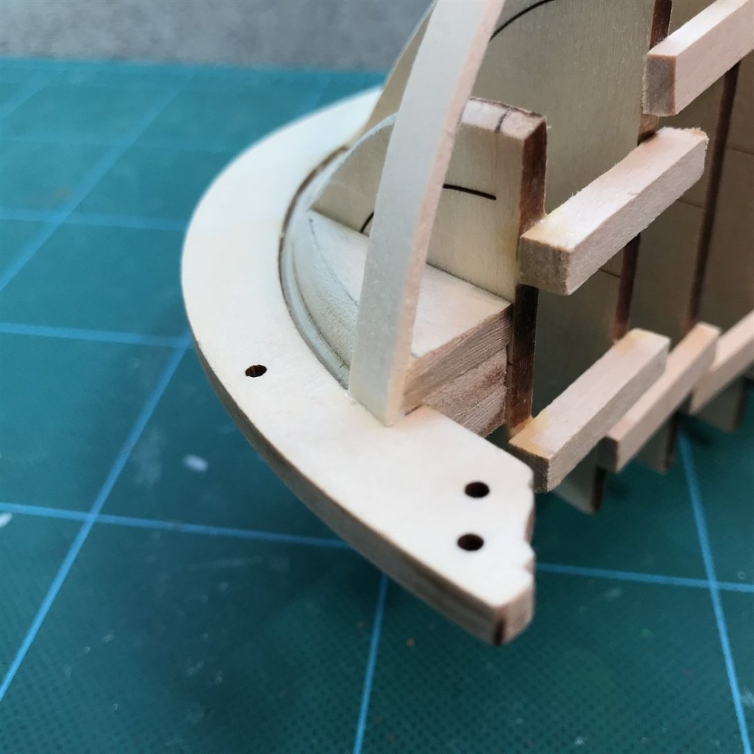
Looking ahead at the bending job for the bow parts, I traced an outline of the curve there at the top of the frames and cobbled up a typical crude jig
- CiscoH, Ryland Craze and ccoyle
-
3
-
So here we go, a YALBB (Yet Another Long Boat Build) thread. Maybe repetitive, but I've found in my past life of Card Modeling that doing a build thread encourages better work since people will be looking, so please bear with me. As the title states, this is my first wooden ship build. Technically not 100% correct as I just finished the NRG Half-Hull trainer - but this is the first real kit.

Here we start with the 4 keel and keelson pieces rabbetted and glued up.
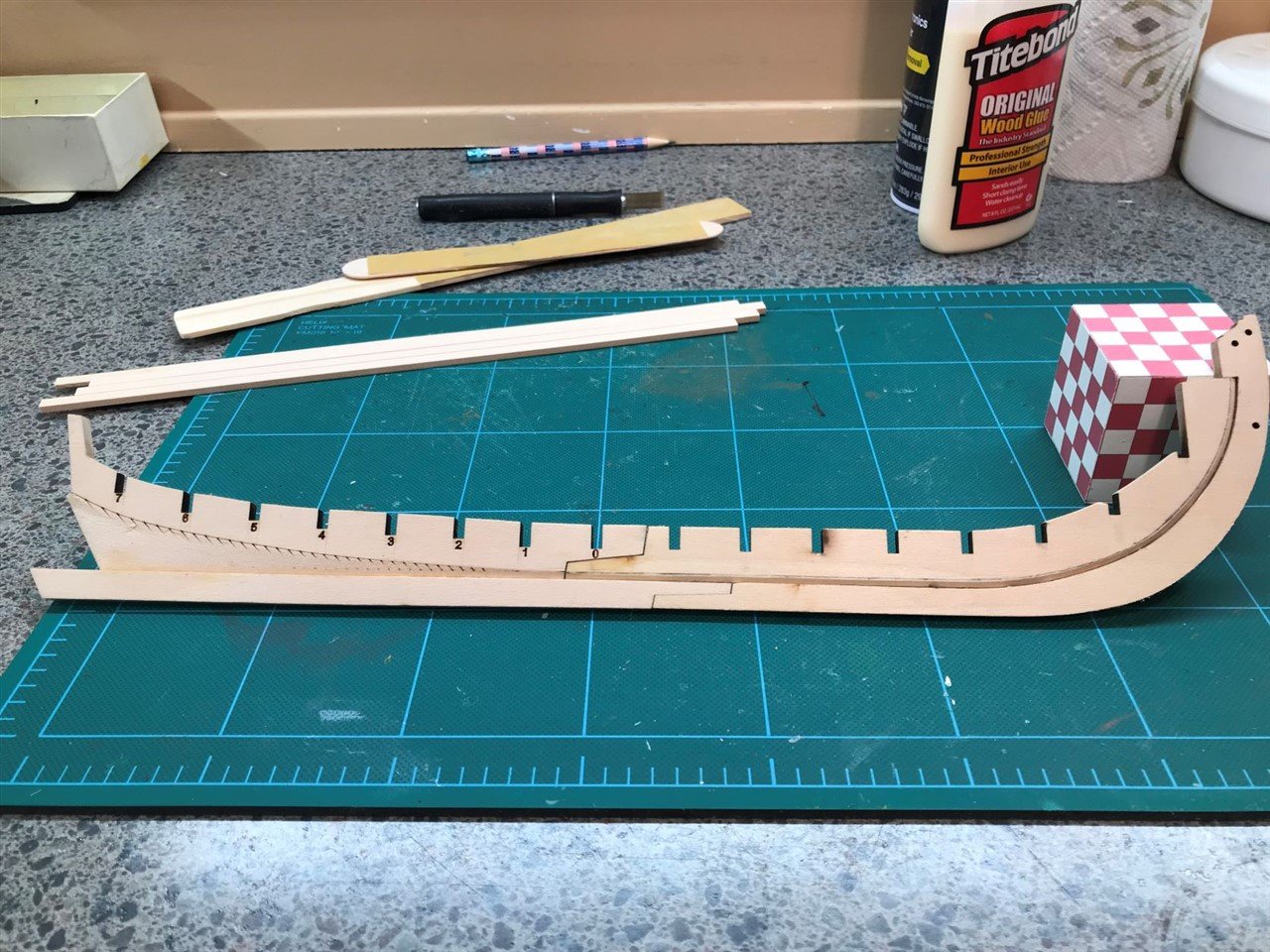
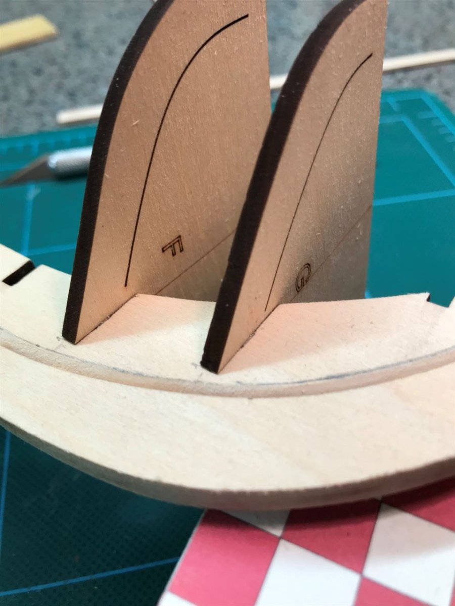
Next I dry fit all the bulkheads with an eye toward where they fell in relation to the bearding line when shoved all the way down. As others have found, there are a few that will go a little too far down and will need to be glued a smidge higher. Alternatively, I have bulkheads F and G that are a good bit too high. I just deepened the keelson notches for those 2.
One thing to watch out for when dry fitting and handling the formers that have pointed bottoms, they are fragile and the way the grain runs easy to break the tips. Ask me how I know. 😒

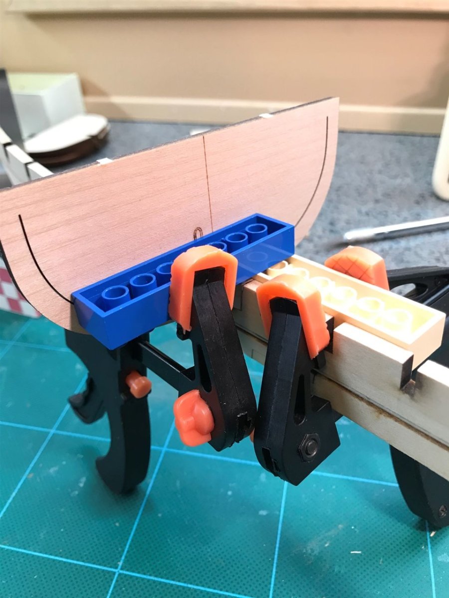
Gluing bulkhead 0. I tried a variation on the lego block square (verifying it with a machinist square too of course).

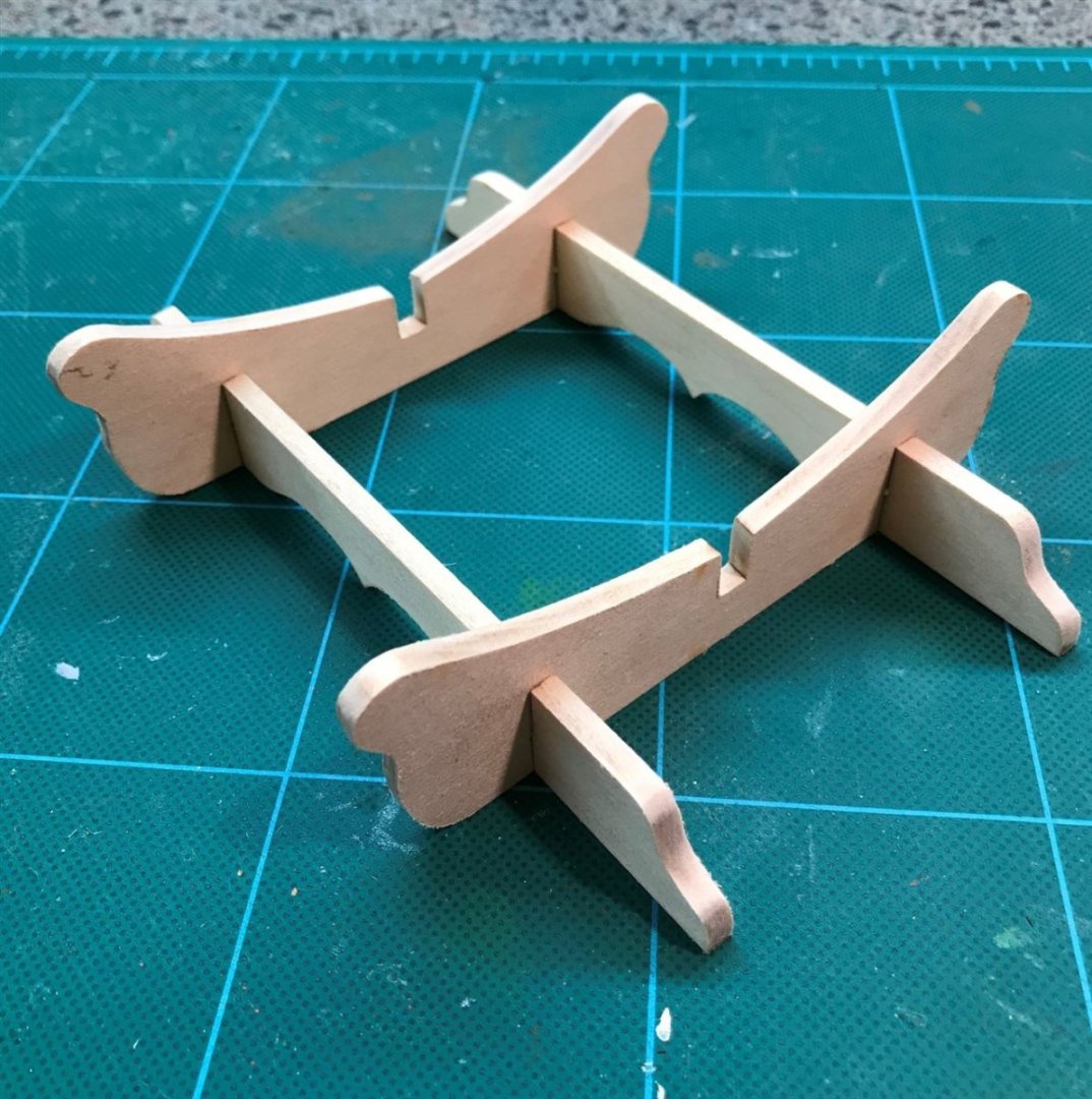
While bulkhead 0 dries, let's make the stand. Nice that a stand is provided, as I know lots of kits don't. The instructions say to paint it Hull Yellow Ocre, but I'm not feeling that. I think I'll stain it instead, so it's important to try to get all the char sanded off.
That's all for today, next will finish the bulkheads and bracing.
Rick
- CiscoH, allanyed, Prowler901 and 1 other
-
4
-
Hi all,
Very pleased to find such a well organized and info-rich site! I have done some ships in plastic many years ago and have frequently desired to venture into wood, but feared I would not have the time I’d like to devote. Well the kids are off the payroll and retirement looms pretty close so it’s time, before all my eyesight goes! 🙂
I have been off and on into Card Modeling for a number of years, mostly aircraft (@ccoyle, I think I recognize you from papermodelers.com and other places, nice to see a familiar “face” here).
I have recently ordered the NRG half-hull training kit and will be starting there to see if I have any aptitude at all for this - fingers crossed!
Rick
- thibaultron, Keith Black, mtaylor and 3 others
-
6


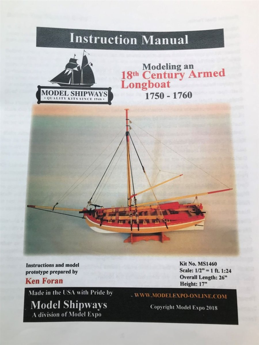

18th Century Armed Longboat by rlwhitt - FINISHED - Model Shipways - 1:24 - First Build
in - Kit build logs for subjects built from 1751 - 1800
Posted
DeadEyes and Chainplates
My kit was missing one of the white metal "chainplate" parts that are also the band wrapping around the deadeyes. I put in a request for missing part the day I received the kit and that's been almost a month. Still no part. So I got impatient and decided to try to make something. I've seen pics of them made this way, with bits of wire and metal strip, so thought I'd give it a go.
I think they look at least as good as the ones that the kit parts would make. Not accurate for this boat, I know. But neither are the kit supplied ones, so whatever.