JacquesCousteau
-
Posts
1,388 -
Joined
-
Last visited
6 Followers


About JacquesCousteau

-
 JacquesCousteau reacted to a post in a topic:
Whaleboats
JacquesCousteau reacted to a post in a topic:
Whaleboats
-
JacquesCousteau reacted to a post in a topic:
Billy 1938 by Keith Black - FINISHED - 1:120 Scale - Homemade Sternwheeler
-
JacquesCousteau reacted to a post in a topic:
Billy 1938 by Keith Black - FINISHED - 1:120 Scale - Homemade Sternwheeler
-
Ryland Craze reacted to a post in a topic:
Whaleboats
-
JacquesCousteau reacted to a post in a topic:
Billy 1938 by Keith Black - FINISHED - 1:120 Scale - Homemade Sternwheeler
-
 Keith Black reacted to a post in a topic:
Billy 1938 by Keith Black - FINISHED - 1:120 Scale - Homemade Sternwheeler
Keith Black reacted to a post in a topic:
Billy 1938 by Keith Black - FINISHED - 1:120 Scale - Homemade Sternwheeler
-
John Ruy reacted to a post in a topic:
Billy 1938 by Keith Black - FINISHED - 1:120 Scale - Homemade Sternwheeler
-
Paul Le Wol reacted to a post in a topic:
Billy 1938 by Keith Black - FINISHED - 1:120 Scale - Homemade Sternwheeler
-
JacquesCousteau reacted to a post in a topic:
Maine Lobster Boat by Scott Crouse (bartbandy) - Midwest Products - 1:16
-
JacquesCousteau reacted to a post in a topic:
Emma C Berry by cdrusn89 - Model Shipways - 1/32
-
 Congratulations! Once again, a fascinating, unique build, brought to life with real craftsmanship.
- 363 replies
-
- 3
-
-
-
- Billy
- sternwheeler
- (and 1 more)
-
 JacquesCousteau reacted to a post in a topic:
Billy 1938 by Keith Black - FINISHED - 1:120 Scale - Homemade Sternwheeler
JacquesCousteau reacted to a post in a topic:
Billy 1938 by Keith Black - FINISHED - 1:120 Scale - Homemade Sternwheeler
-
JacquesCousteau reacted to a post in a topic:
Emma C Berry by cdrusn89 - Model Shipways - 1/32
-
That's a lot of whaleboat kits! If you're a beginner at ship modeling, you may want to choose whichever seems to be the simplest build and have the clearest instructions. Other considerations would be the size/scale (how much display space do you have?) and whether there are helpful build logs for that specific kit. The Model Shipways kit, for instance, is a very cool model and there are several build logs, a plus, but it looks to be rather complex, so probably not a great choice to start with. Disar's kit is known to have very limited instructions, so also probably not a great first choice. The Bluejacket kit, in contrast, seems to be fairly simple in terms of hull structure (it's a bit simplified compared to the model shipways kit), and there are several build logs here. Its relatively small scale might make some aspects a little challenging, but it might be a good bet to start with.
-
JacquesCousteau reacted to a post in a topic:
Whaleboats
-
JacquesCousteau reacted to a post in a topic:
USF Essex 1799 by RossR - Model Shipways - 1:76
-
KLarsen reacted to a post in a topic:
La Mahonesa by KLarsen - Scale 1/48 - stern cross-section
-
Dr PR reacted to a post in a topic:
Muscongus Bay Lobster Smack by JacquesCousteau - Model Shipways - 1:32 - Rescaled and Modified
-
Harvey Golden reacted to a post in a topic:
Cutter Luisito by GioMun - 1/48 - A small cutter built to survive a shipwreck in southern seas
-
Bryan Woods reacted to a post in a topic:
Muscongus Bay Lobster Smack by JacquesCousteau - Model Shipways - 1:32 - Rescaled and Modified
-
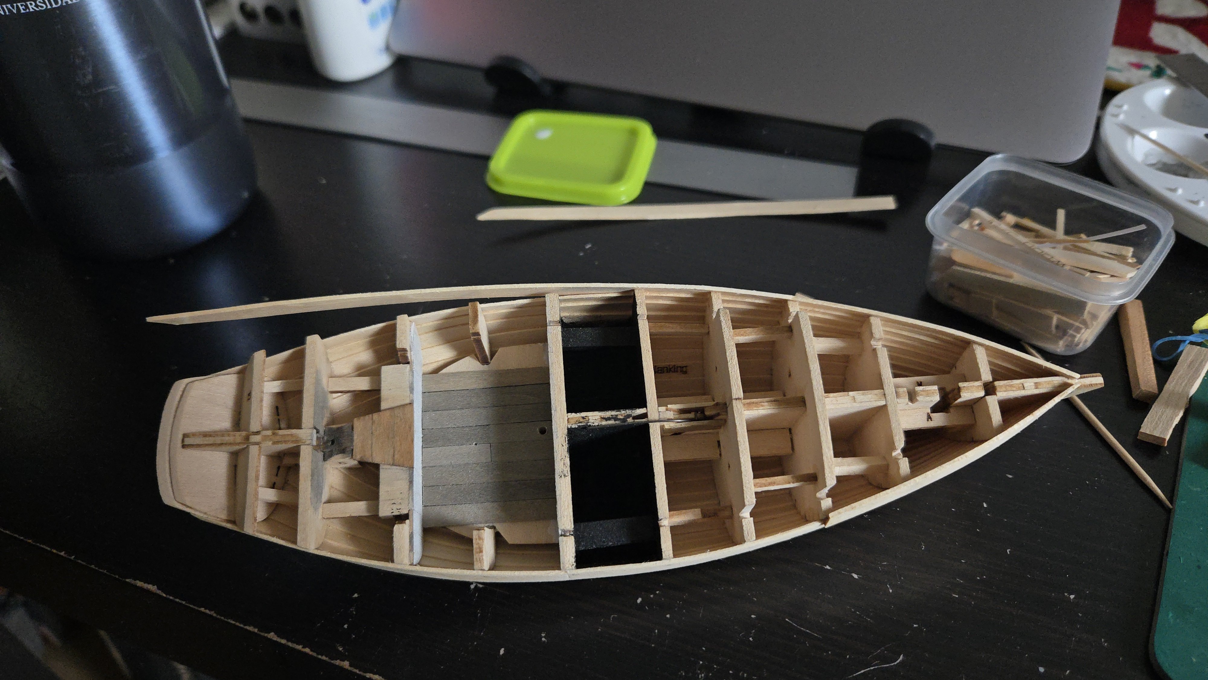
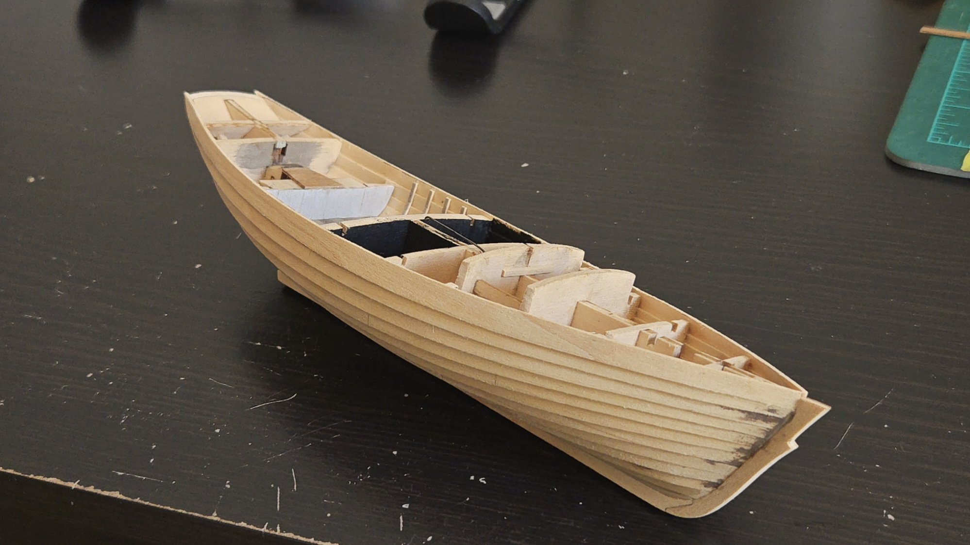
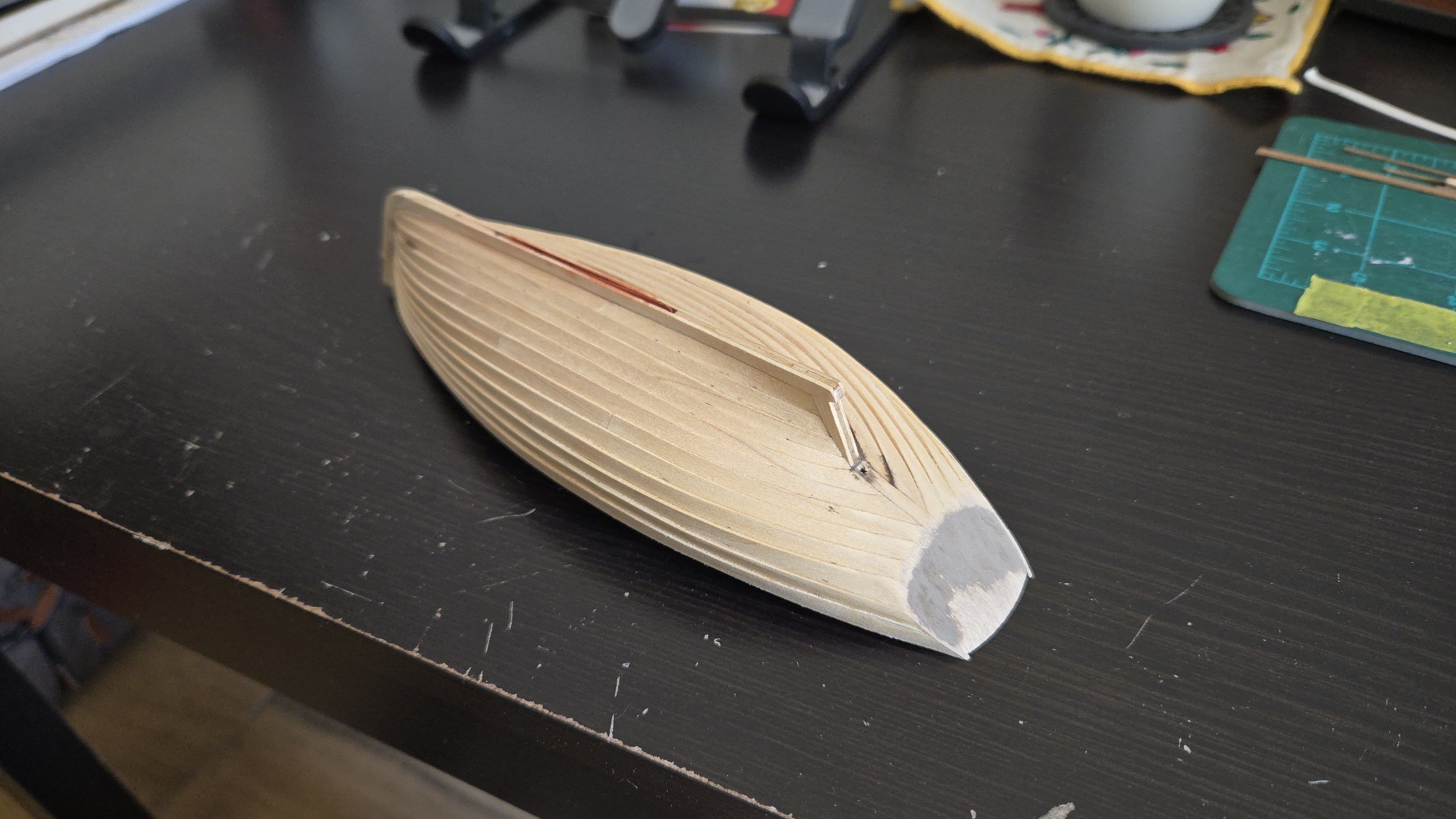
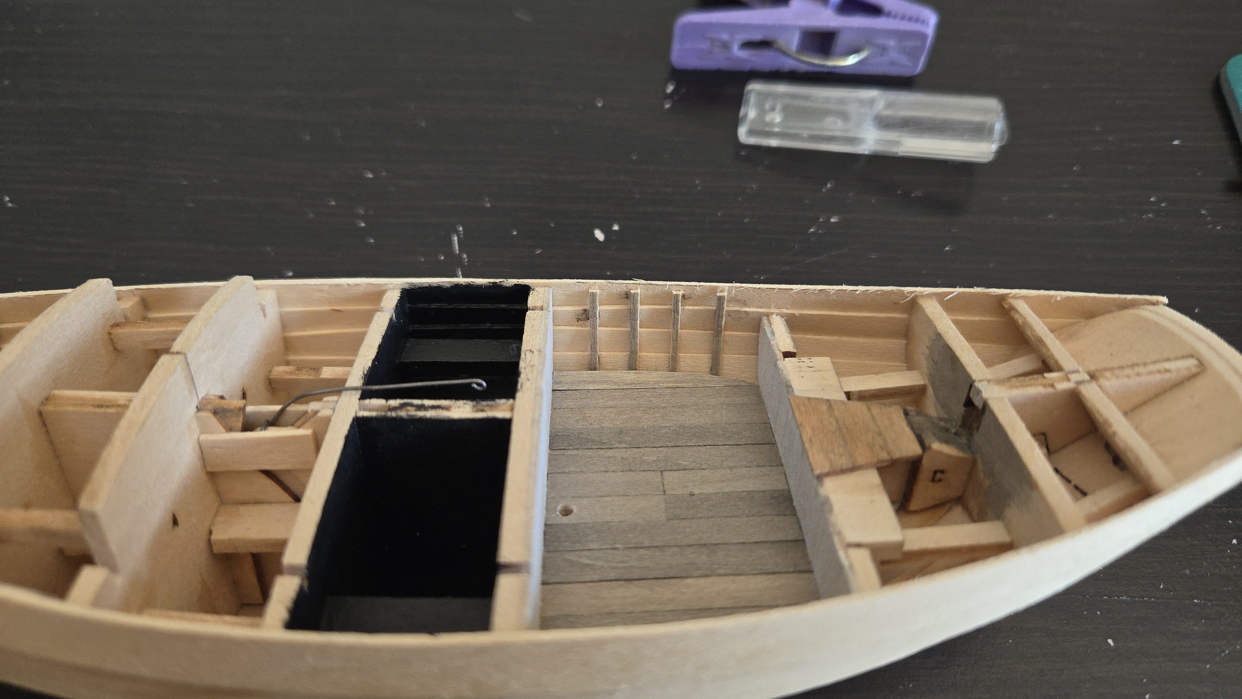
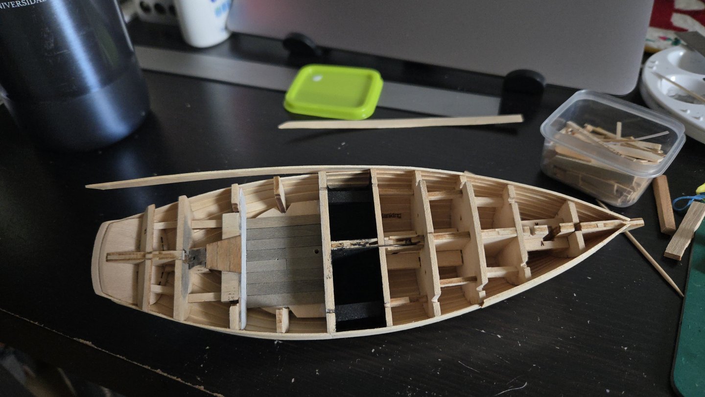
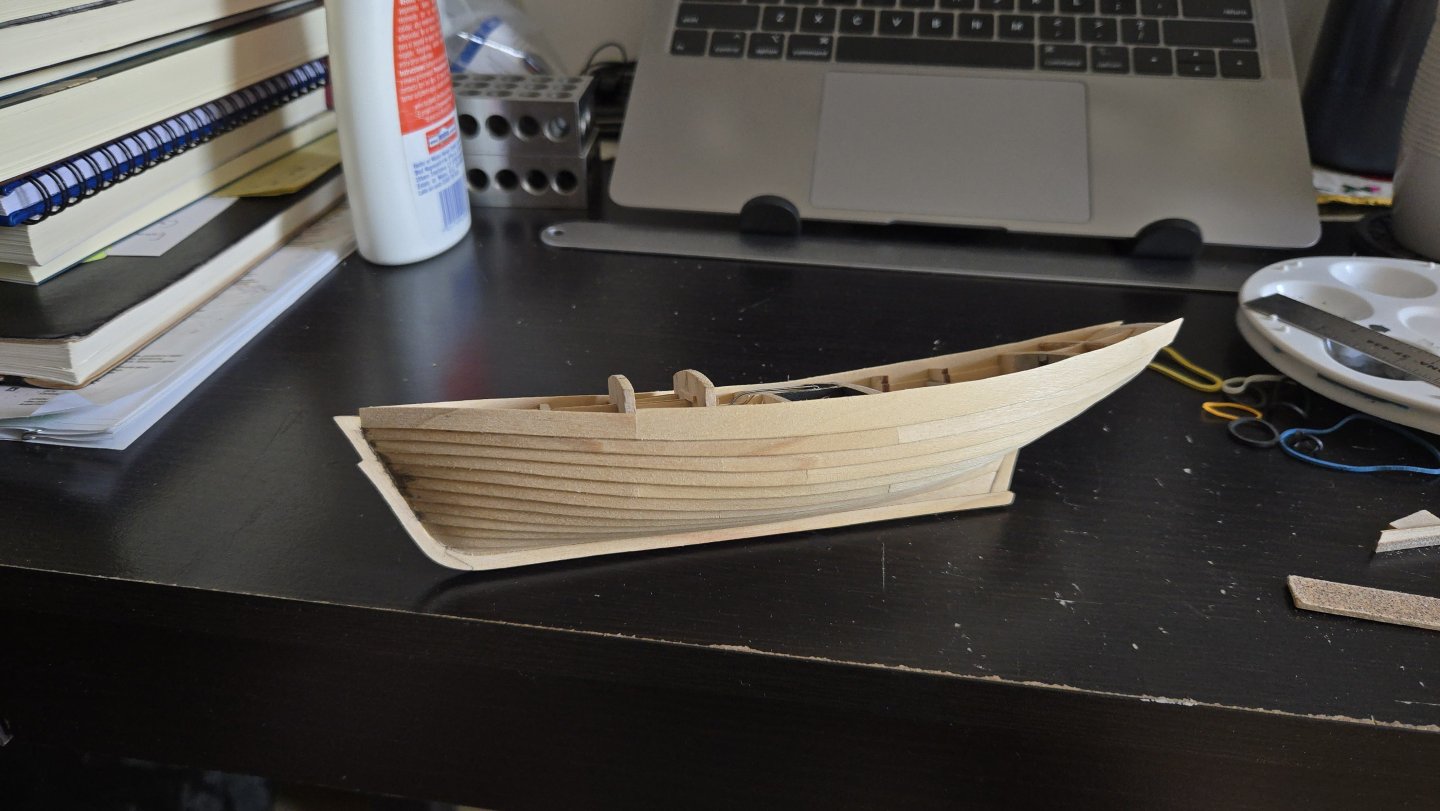
Between travel, work, and focusing on other builds for a while, it's been a long while since I made progress on the Bateau. The next step is planking. I decided to plank the wales first, then up to the sheer strake, in order to help strengthen the framework before I get to the more complex curves of the lower hull. My planking method is the same I have used since learning on the NRG Half-Hull kit. I've explained it elsewhere, but may as well go over it here. With the plank locations marked out, I put Tamiya yellow masking tape over the frames. It's thin enough that the markings on the frames can be traced. I should note that, according to the drawings, the wales should be made of two thick strakes running continuously from stem to stern. I don't want to try to bend thicker wood, so I'll make my wales in two layers. The inner layer will also be made of several planks per strake, as shorter planks are more manageable. None of this will be visible once the outer layer is on. After marking the plank shape, I move the tape to a sheet of planking material--in this case, 3/64-inch thick alder--and use a French curve to connect the markings in a smooth curve. I then cut out the plank, cutting slightly oversized. I sanded the edges a bit to get it closer to the final shape, but I held off on final shaping yet--given the tight curve, it's tricky to hold the plank in place to check fit. So, I then soaked the plank, heated it, and clamped it to dry in place. This is my first time planking with alder. As can be seen, the alder curved beautifully. I then sanded it to its final shape. Now that it's curved, it was much easier to check its fit. I then glued and clamped it into place. As the model is of an open boat, I made sure to clean up any excess glue with a damp brush and a knife--there's still a little to clean, below. And with that, about 11 months after I first made sawdust on this build, the first plank is on! One down, many, many more to go.


- 141 replies
-
- 11
-
-
- ancre
- Bateau de Lanveoc
- (and 2 more)
-
Very nice work! The pump, especially, looks great--it almost looks like it actually works. For the anchor, I'd noticed that I didn't see any windlasses in any photos of Chilean Lanchas Chilotas (which are pretty similar vessels). I'd be curious to know whether they ever improvised any way to hoist the anchor with blocks--the question is especially on my mind as my current Bateau de Lanvéoc build is noted as having a pretty heavy anchor, but there's no way to raise it shown in the drawings.
-
Thanks, all! On the exterior, I shellacked the hull and lightly sanded to remove the raised grain. I also decided that now is a good time to add the rudder, as I'll need to paint it when I paint the hull. I first added a small brass pin at the bottom, that will anchor one end of the brass rod I'm using for the rudder shaft. It was then straightforward to add the rod, mark where to cut it, cut it, place it, and superglue on the rudder. The completed assembly currently can turn. In the cockpit, I decided to paint the frames and inner faces of the hull planking the same white that I used for the cockpit's fore and aft bulkheads. This was originally done with alternating layers of dark and white acrylic washes. This attempt turned out a little darker and grimier-looking. Unfortunately, the washes loosened the glue on several frames, so I ended up supergluing them back into place. I also added extra frame pieces coming up from the bench-level bulkhead and aft of it--I don't know if these will be visible, but better that they're there in case it can be seen. Next, the benches. For this, I was inspired by this photo of a Friendship Sloop, which shows a framework extending back to the frames. Source After considering how best to handle these and their delicate framework, I glued them in place. I then added the foremost horizontal beams, using tweezers to manuever the pieces into position and securely glued to the underside of the bench and to the hull/frame. Once those dried, I was able to glue one more plank on the back end of each bench. I then added an intermediate horizontal support at the level of the middle bench leg. After that, I added some low backs to the benches and around the rudder head housing. I also added a cap piece going over the aft bulkhead--it may be disproportionately thick, but it looks better than the bare wood (and it really shouldn't be very visible). With that, I think the cockpit is basically finished. Below, I placed the bilge pump, although I think I may just leave it off entirely until near the end of the build. I'll need to think whether there would be anything else in the cockpit--some sort of hanger on the bulkhead to securely stow a gaff hook? In any case, the cockpit has been a lot of fun to build, and I'm glad I decided to modify it from the kit design.


-
If you're interested in building it as a schooner, there's a very interesting build log that will probably be helpful: There are photos online that will probably help with mast/yard proportions, as well.
-
Very interested to follow along with this build!
-
You can also anneal it over a stove burner (provided you have a gas stove, that is). Very nice work!
-
Very nice work! Do you have any photos of the entire model?
-
Very sharp! Great use of jigs to get a precise and consistent fit.
-
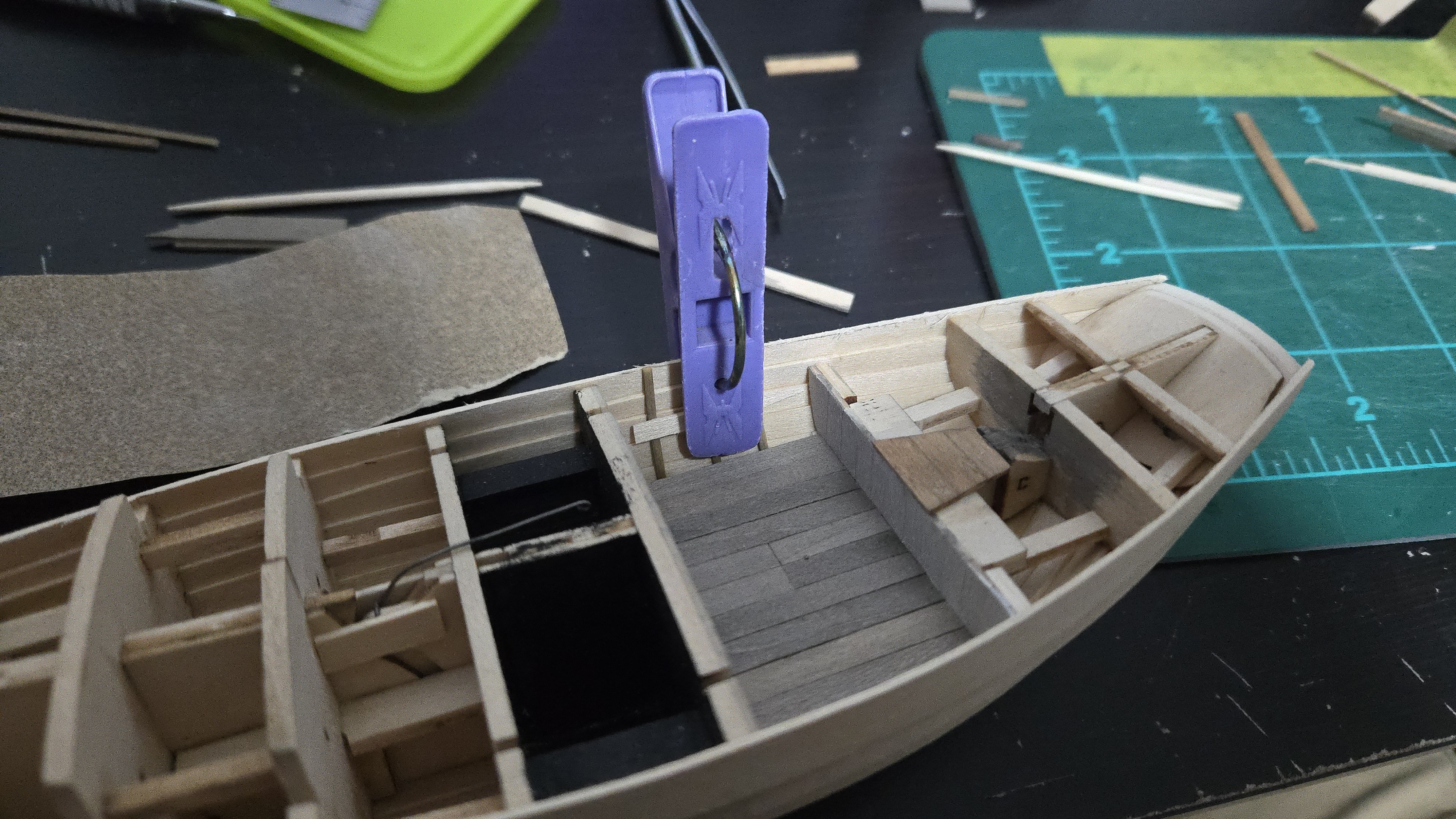
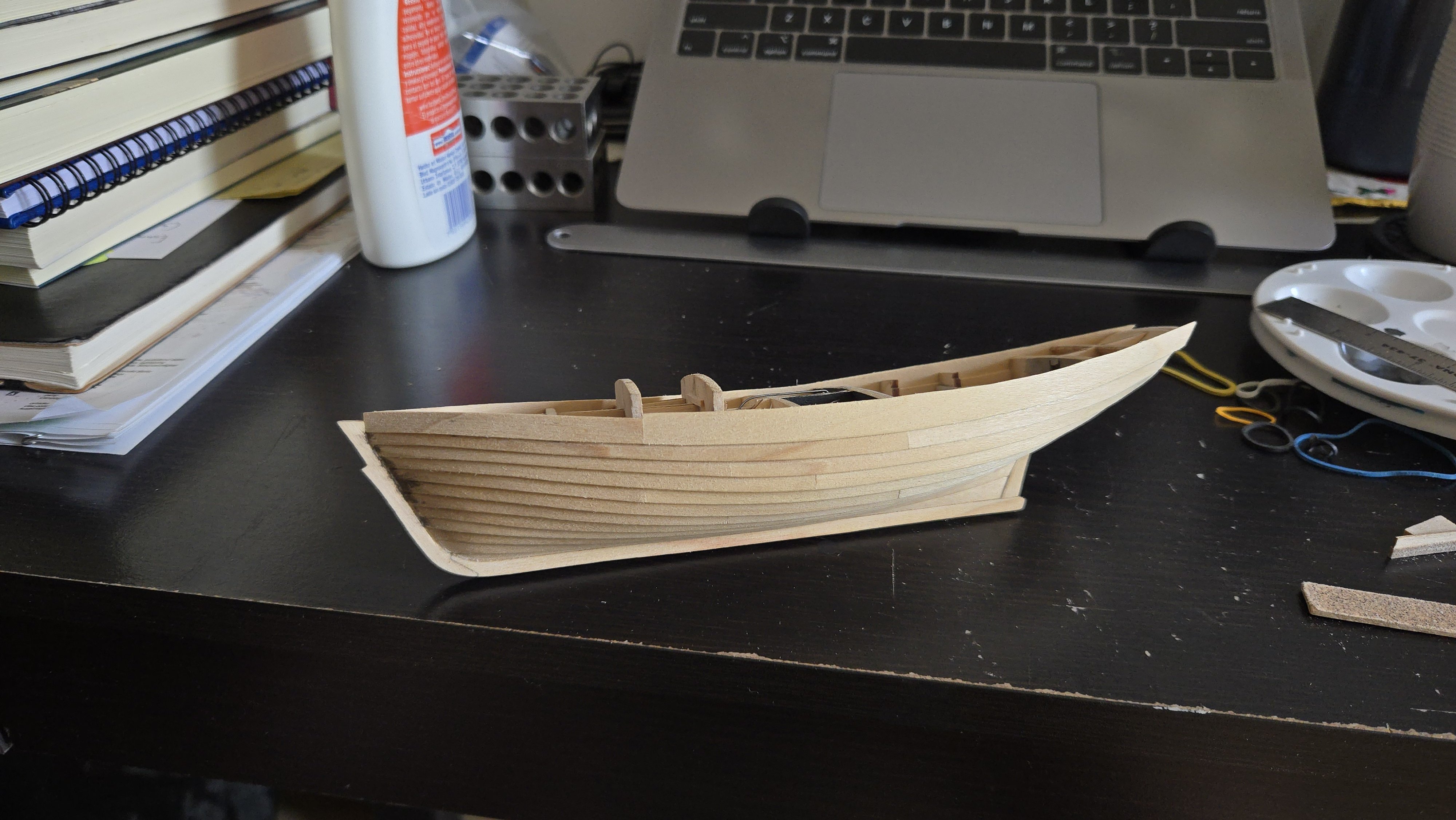
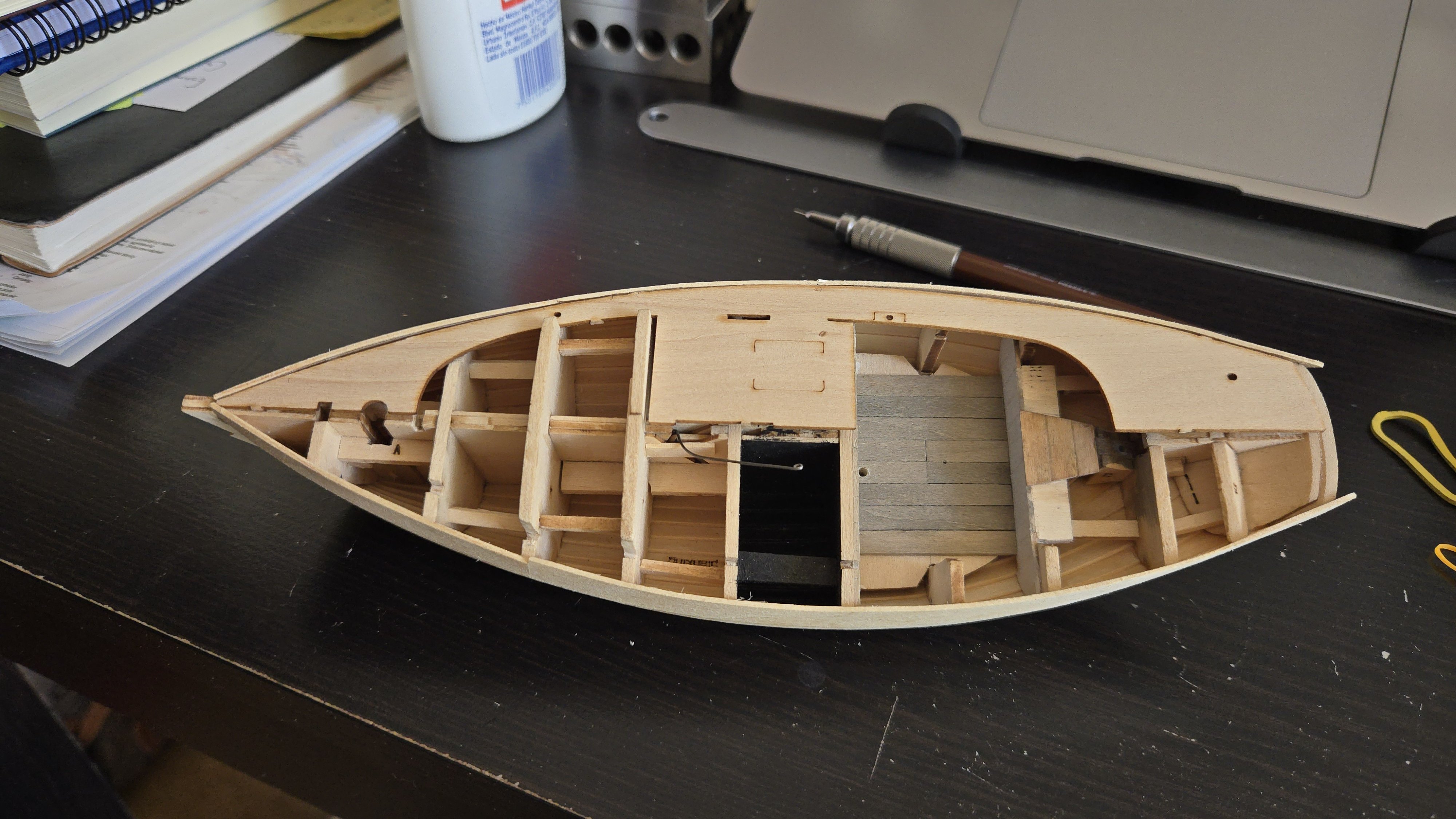
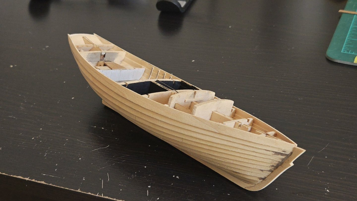
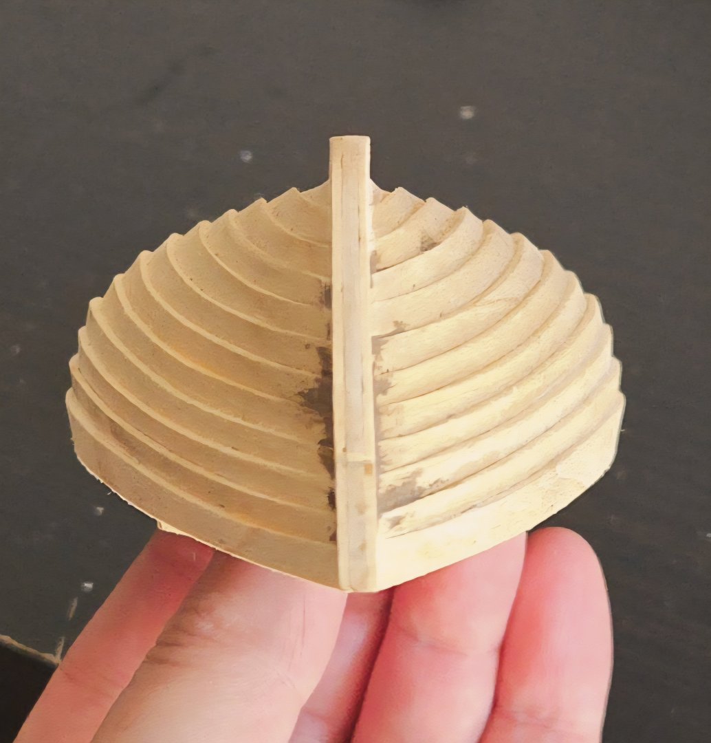
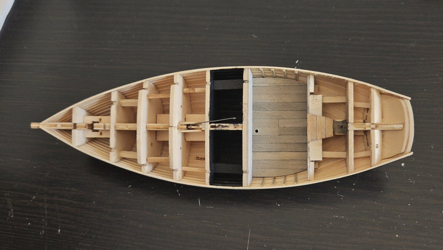
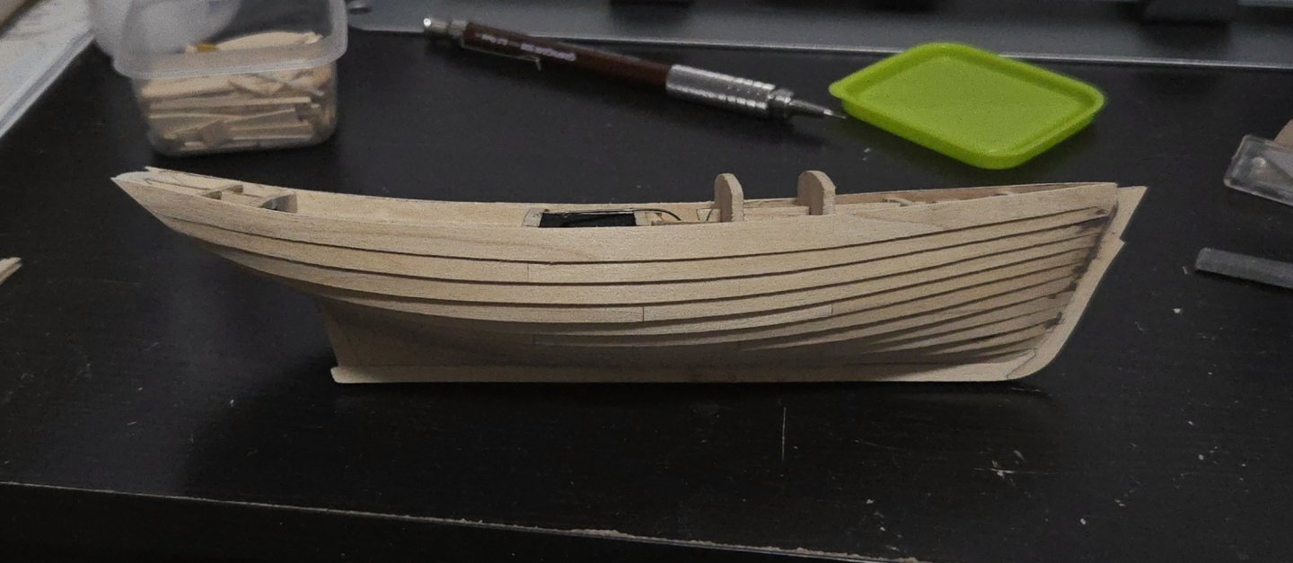
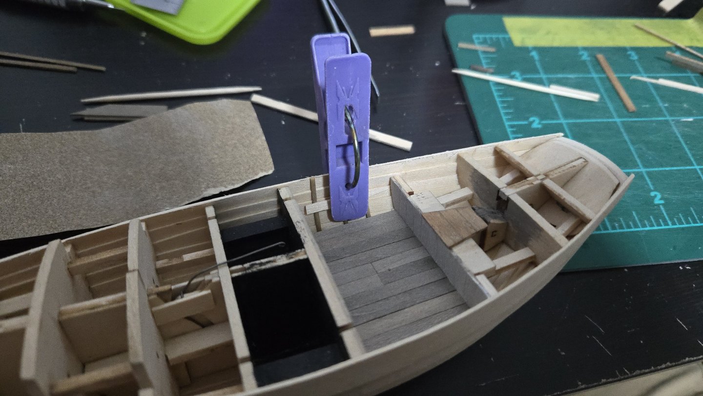
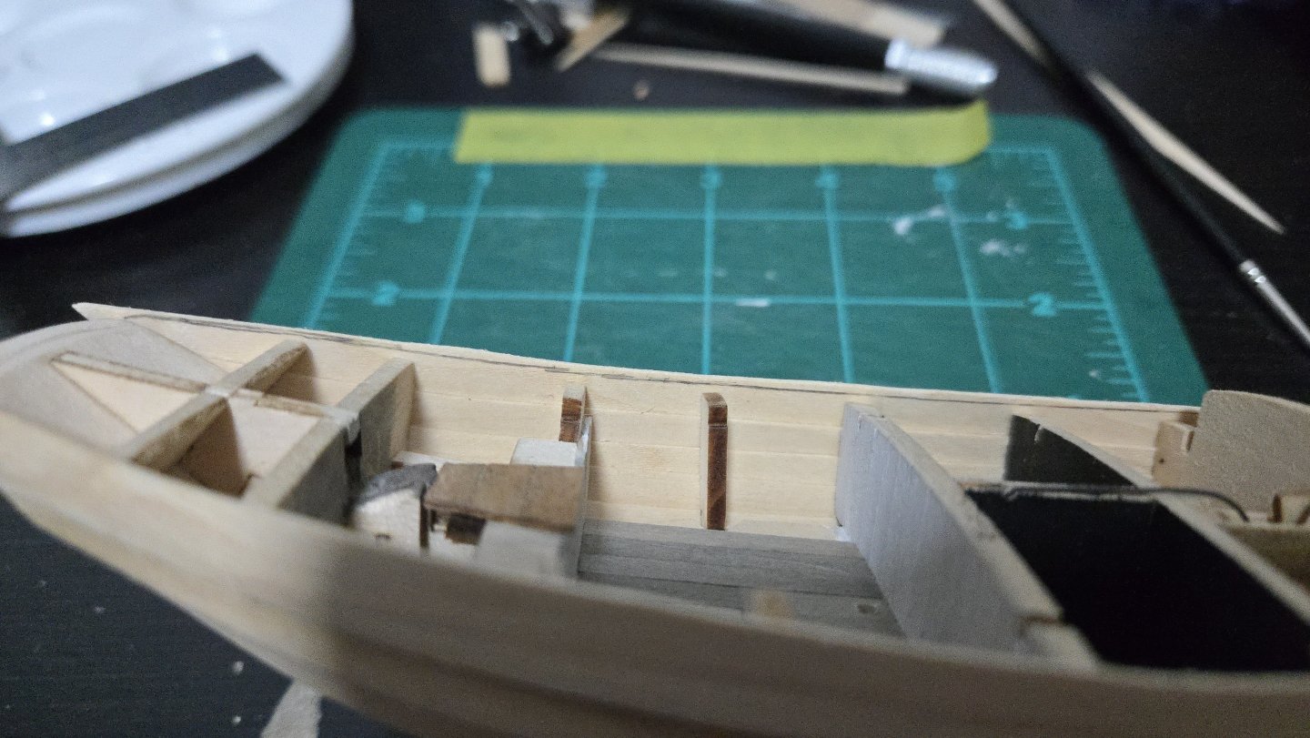
Thanks, all! @Kenchington, I'm planning on trimming the pump handle shorter, but for now I'm leaving it long--it's a tiny piece and is harder to lose if it's slightly bigger. At long last, the planking is finished! I have to admit that it took way longer than I had thought it would, but I'm pleased with how it turned out and glad I decided to give lapstrake planking a shot. I found that I couldn't really clamp the sheer strake for gluing: there was no overhanging bulkhead to clamp to, and as the plank ends above the bulkhead, rubber bands exerted too much leverage and tilted the plank. I had to go by hand instead, gluing in sections. It took a while, but I was able to listen to music or watch movies while holding it in place. The sheer strake was deliberately oversized on the upper edge. I then dry fit the deck and marked the proper height with a pencil. Then, I shaved and sanded the sheer strake down, leaving just a little of the pencil line. It can be sanded smooth to the final fit once the subdeck is in place. (Below, there's still a bit to trim). Once trimmed, it looked quite nice. The photo below highlights a few points where I need to smooth off some lower plank edges, which I will probably do after adding some shellac--some of the basswood was a bit stringy and could be usefully sealed. I then removed the bulkhead tabs from the cockpit and began finishing the floor planking. The hull shell around the cockpit was quite sturdy. I also bent some 1/32-inch thick stringers to represent the frames. I found that clamping as below indented them a bit, but for actual gluing, I rounded off the edges of a bit of scrap to press the frames into shape and it worked better. Initially I planned on doing 3 frames in the space, although I upped it to 4 before gluing. Below, the cockpit fully planked, four frames added per side, and the tops trimmed. They're still a little dented, but they'll be barely visible below/behind the deck, coaming, and benches, so I'm not too worried. Same with one of the frames being slightly misaligned due to sliding a bit while clamping. I also trimmed and sanded the transom area, and added some wood filler to smooth the planking ends. You can also see that I filled in the large square gap around the rudder shaft hole, and later drilled it out. The lapstrake planking is a neat effect, I have to say. And the current state of the build:


-
Very interesting work on what's in a name, thank you for sharing! I have to admit that I've often been confounded by the cutter vs sloop distinction. If I understand usual present-day usage, a Friendship Sloop can technically be called a cutter (though I've never seen it referred to as such) because of the two headsails? Not to mention the complexity of trying to disentangle what writers past and present mean by different terms--sometimes it's hard to tell whether they're using the term used by the boat operators themselves, or applying their own label. Sometimes it's obvious, though. Amusingly, one traveler to Lake Chapala, Mexico, around 1900 referred to the local flat-bottomed boats as "smacks," apparently solely because they were used for fishing. (While another writer called them "schooners" despite them all being single-masted... thank goodness I could rely on photos instead of written descriptions for my build!) One question: so would the Muscongus Bay Sloop/Boat/Smack have had hopes drilled in the planking for the live wells? I'd imagine so, but I haven't seen this in any plans or images.
-
Excellent work! The little details really make it something special.
-
Amazing work! The view from inside the hull is really incredible.