
Der Alte Rentner
-
Posts
1,045 -
Joined
-
Last visited
3 Followers


About Der Alte Rentner

- Birthday December 7
Recent Profile Visitors
3,025 profile views


-
 lawrence101 reacted to a post in a topic:
USS Constitution by mtbediz - 1:76
lawrence101 reacted to a post in a topic:
USS Constitution by mtbediz - 1:76
-
 GGibson reacted to a post in a topic:
USS Constitution by mtbediz - 1:76
GGibson reacted to a post in a topic:
USS Constitution by mtbediz - 1:76
-
mtbediz reacted to a post in a topic:
USS Constitution by mtbediz - 1:76
-
 mtbediz reacted to a post in a topic:
USS Constitution by mtbediz - 1:76
mtbediz reacted to a post in a topic:
USS Constitution by mtbediz - 1:76
-
mtbediz reacted to a post in a topic:
USS Constitution by mtbediz - 1:76
-

USS Constitution by mtbediz - 1:76
Der Alte Rentner replied to mtbediz's topic in - Build logs for subjects built 1751 - 1800
Ha! I wish I'd gotten that advice some months ago. Oh well, what's a little more trouble at this point? 😁 -
USS Constitution by mtbediz - 1:76
Der Alte Rentner replied to mtbediz's topic in - Build logs for subjects built 1751 - 1800
I'll chime in along with Jon and Gregg - truly inspiring work, Mustafa! -
USS Constitution by mtbediz - 1:76
Der Alte Rentner replied to mtbediz's topic in - Build logs for subjects built 1751 - 1800
That's a very tempting offer. Let me see how they compare to the Syren blocks I've been using, and I'll get back to you via private channel. Thank you -
Der Alte Rentner reacted to a post in a topic:
USS Constitution by GGibson - Model Shipways - 1:76.8
-
Der Alte Rentner reacted to a post in a topic:
USS Constitution by GGibson - Model Shipways - 1:76.8
-
Der Alte Rentner reacted to a post in a topic:
USS Constitution by Unegawahya - Model Shipways - scale 1:76
-
Der Alte Rentner reacted to a post in a topic:
USS Constitution by Unegawahya - Model Shipways - scale 1:76
-
Stevenleehills reacted to a post in a topic:
USS Constitution by mtbediz - 1:76
-
Unegawahya reacted to a post in a topic:
USS Constitution by Der Alte Rentner - Model Shipways - 1/76
-
Unegawahya reacted to a post in a topic:
USS Constitution by Der Alte Rentner - Model Shipways - 1/76
-
mtbediz reacted to a post in a topic:
USS Constitution by mtbediz - 1:76
-
GGibson reacted to a post in a topic:
USS Constitution by mtbediz - 1:76
-
USS Constitution by mtbediz - 1:76
Der Alte Rentner replied to mtbediz's topic in - Build logs for subjects built 1751 - 1800
I'm running into many obstacles in my preparations for this vacation. This seems to be driving me to the consensus view. R&R it will be. 😁 -
Der Alte Rentner reacted to a post in a topic:
USS Constitution by mtbediz - 1:76
-
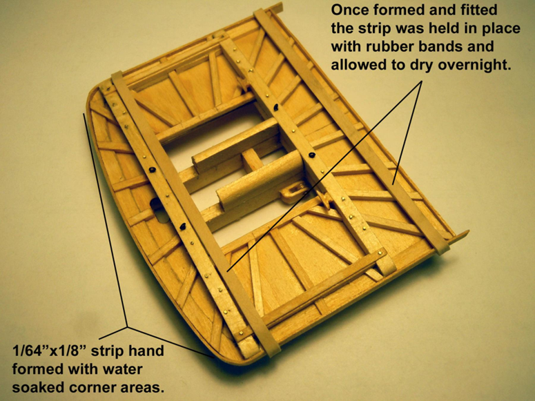
For what it's worth, the 1/64" thick sapele wood strips I used, which came with the Constructo Constitution kit - in case you missed that nugget of information, bent quite easily. I put a length of this into a pot of water and let it simmer a while before wrapping it around the corners. The hardest part was getting rubber bands or clamps on to hold the strip secure while the Titebond glue dried. It wouldn't bend to a hard 90 degrees without splitting. So, for the back edge of the top, I simply fitted a straight segment of sapele and butt jointed it to the bent piece.
-
USS Constitution by mtbediz - 1:76
Der Alte Rentner replied to mtbediz's topic in - Build logs for subjects built 1751 - 1800
While you're still on R&R, could you put some thought into recommending some work that I could take with me on my upcoming R&R trip (starting Saturday). You know that I'm wrapping up the fighting tops on my build, but I won't be taking my mill with me. I also didn't have time to order (or make) a serving machine. That surely limits the options. Still, I'm thinking there will be many blocks to strop. Can you suggest where I focus my priorities for doing that while gone? I would sincerely appreciate it. Thanks -
Der Alte Rentner reacted to a post in a topic:
USS Constitution by Der Alte Rentner - Model Shipways - 1/76
-
 Der Alte Rentner reacted to a post in a topic:
USS Constitution by Der Alte Rentner - Model Shipways - 1/76
Der Alte Rentner reacted to a post in a topic:
USS Constitution by Der Alte Rentner - Model Shipways - 1/76
-
Not as fragile as the basswood that came with the kit. I made my own 1/32" square boxwood stock. Still, your idea to substitute brass for the stanchions is intriguing! I will seek out some of that material and experiment with it. There's no rush. since I'm firmly committed to holding off on adding the rails to the tops until after the rigging is done. Thanks for an excellent suggestion.
-
Der Alte Rentner reacted to a post in a topic:
USS Constitution by Der Alte Rentner - Model Shipways - 1/76
-
Unless the cleats are brass, switching to metal would go against my color scheme. In this case, the material didn't matter as much as the size. If you've got brass cleats that are 1/32" wide, I'd like to know where you got them.
-
As an aside, can someone explain to me why the formatting of these posts displays differently on a desktop versus on a phone? In a couple of my previous posts, I set the text up to be on the right side of the photos. The post looked exactly the way I wanted it to on my desktop, but when viewed on my phone, the text ends up above or below the photos - and there are huge gaps between photos and text. I think going forward, I will resist the urge to get fancy with photo and text placement in these posts.
-
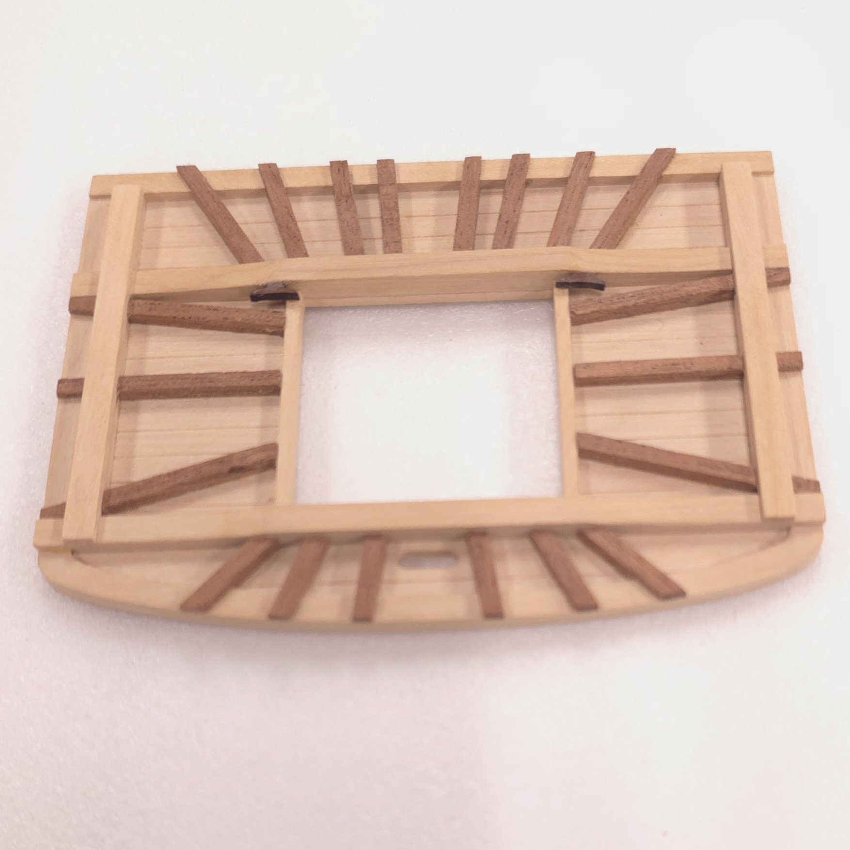
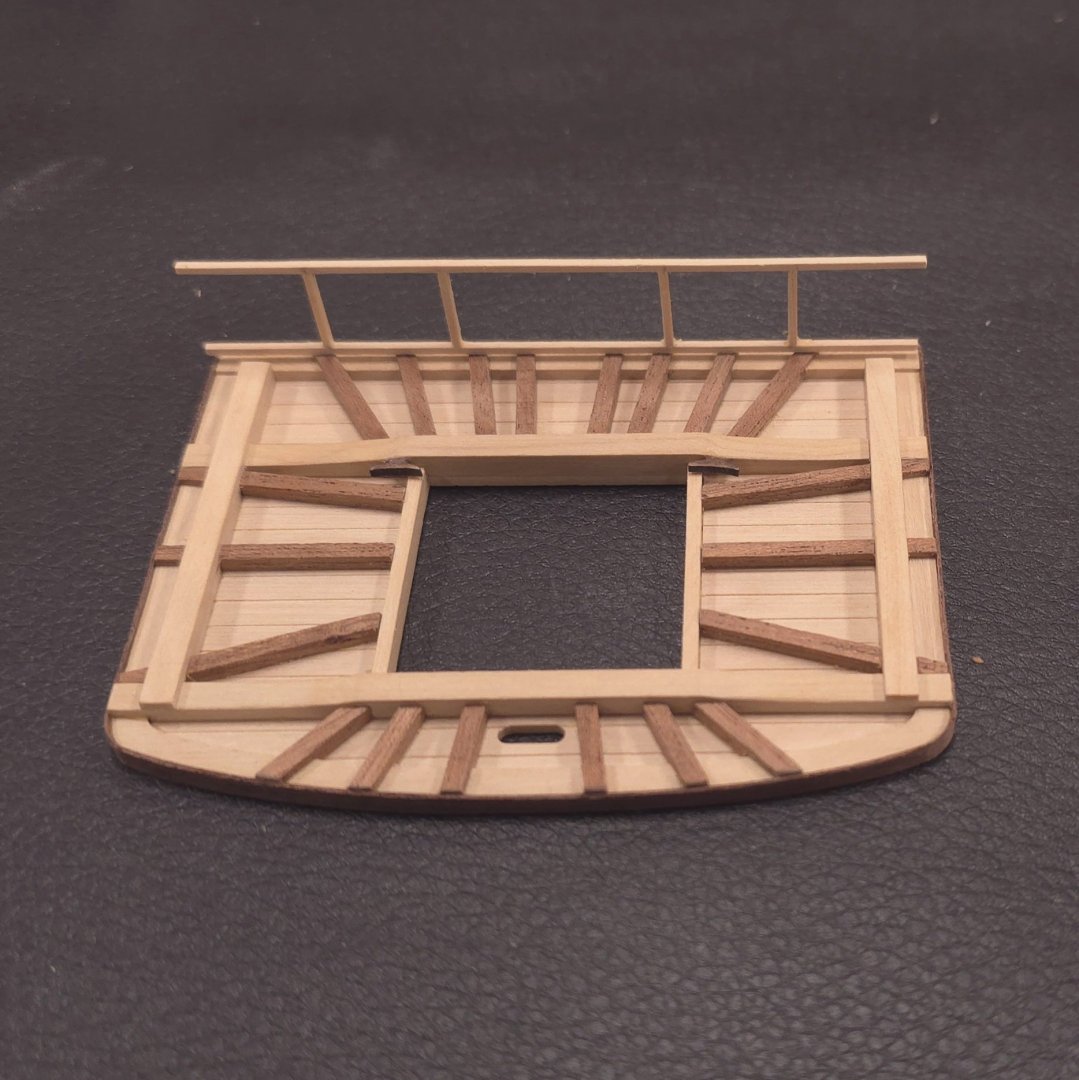
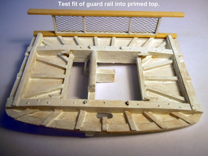
Analysis paralysis is over. I've taken a position. While I am not yet 100% sure I will be adding the top rail, which is right now only dry fitted on the battens, I'm happy with the look of the top itself. As flimsy as the top rail construction is - 1/32" square boxwood per the plan, I can't possibly consider fixing it in place permanently until I've come up with an arrangement like Ken did, where I can easily locate it and glue it after all the rigging is done. I could add some pins at the bottom or mill a 1/32" wide slot into the battens to press fit the bottom board into. Frankly, I've seen models without a top rail, and I'm perfectly happy to live without one. And before anyone asks, no, I will not be messing around with netting. The edge banding went very well. Stay warm out there this weekend.
-
Der Alte Rentner reacted to a post in a topic:
USS Constitution by Der Alte Rentner - Model Shipways - 1/76
-
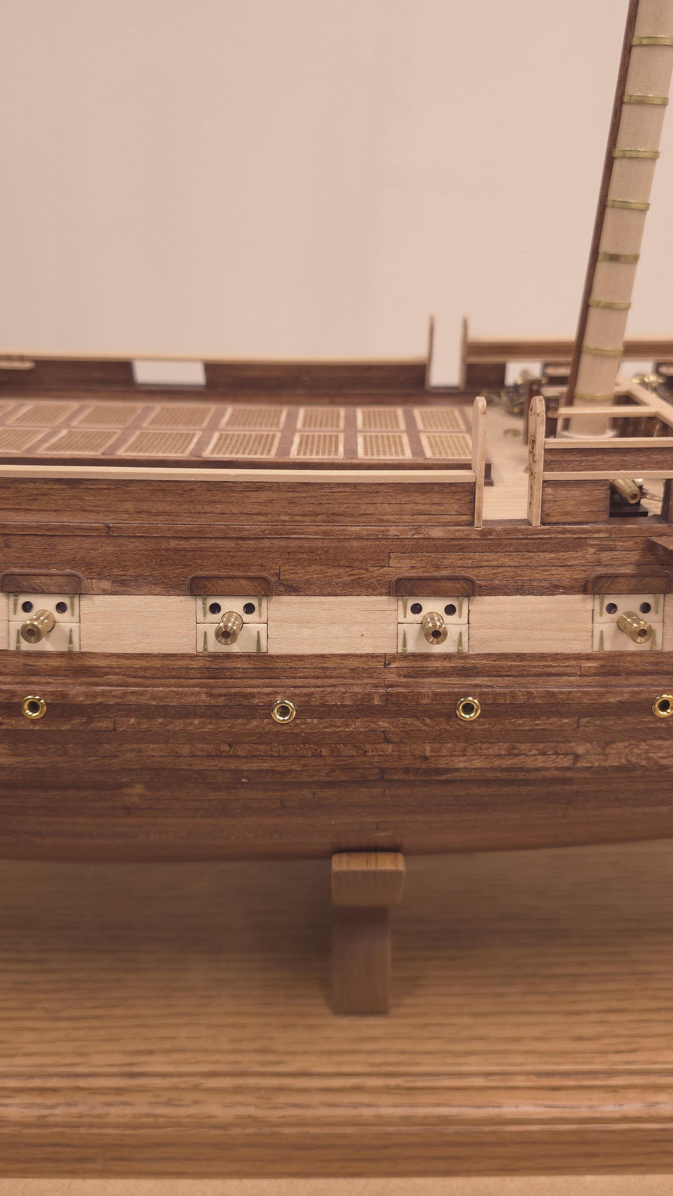
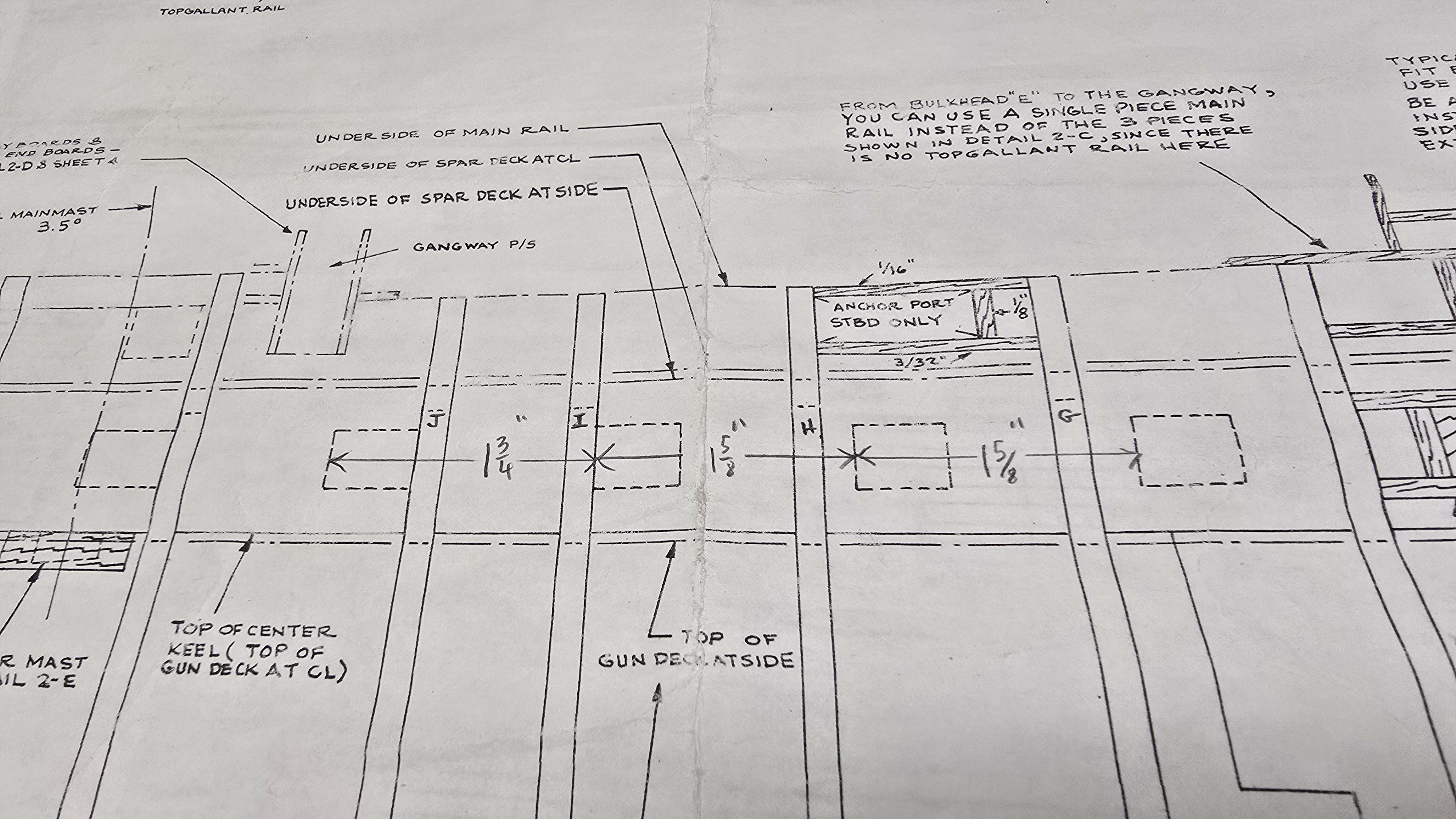
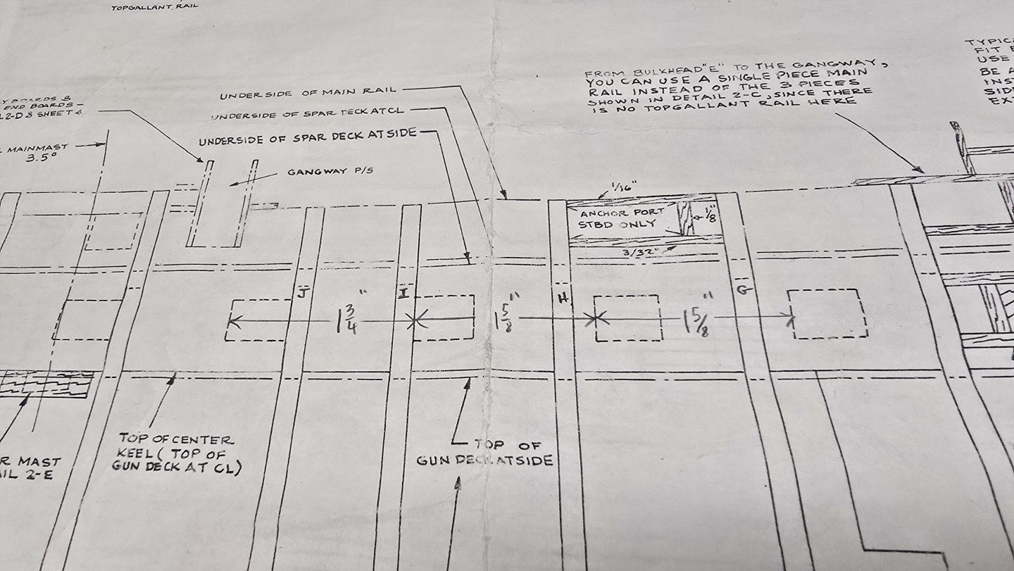
If there's no room up against the extension, you're going to have to compensate by moving the gun, understanding that it's not just a question of the gun - you also have to concern yourself with the location of the gunport lids. If moving the gunport lids 1/8" one way or the other doesn't impact anything else, which seems to be the case for the one in question, make the move. The plans show that the spacing isn't 100% even between the ports anyway. Check the measurements on the plans below. Hope that helps.

-
Der Alte Rentner reacted to a post in a topic:
USS Constitution by Der Alte Rentner - Model Shipways - 1/76
-
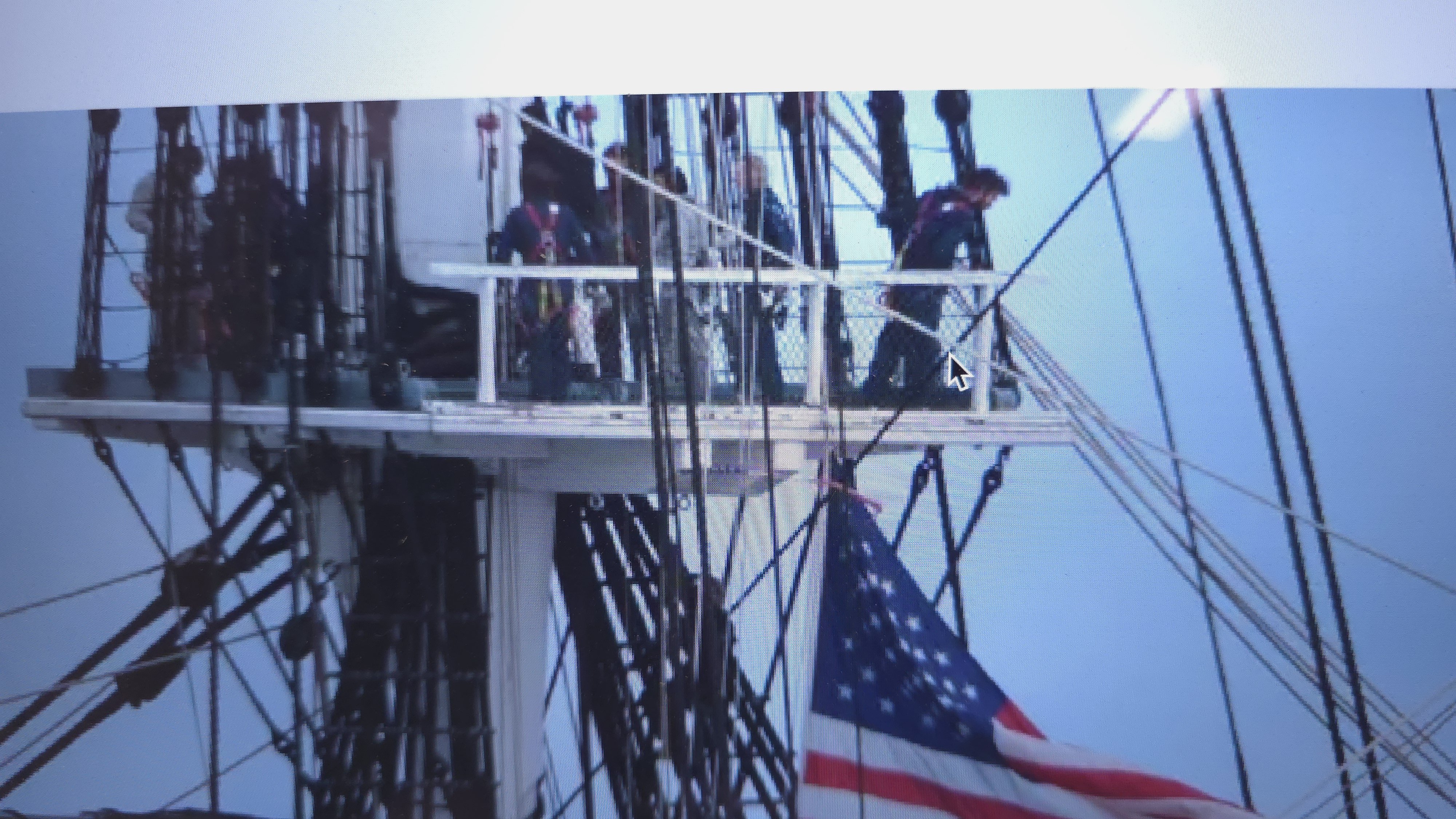
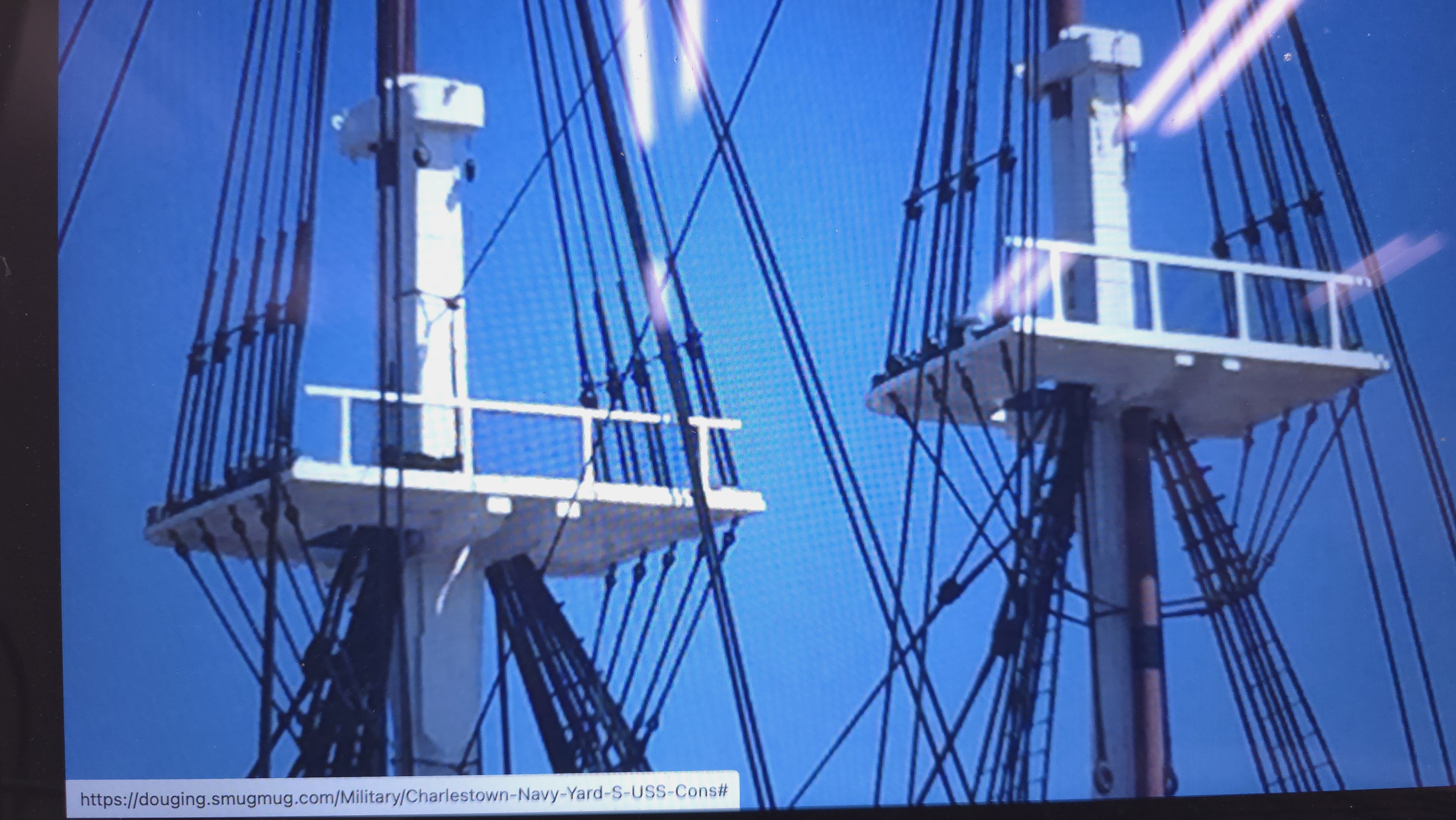
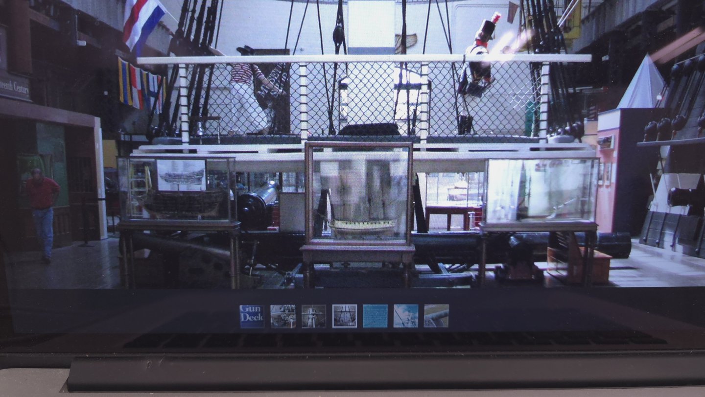
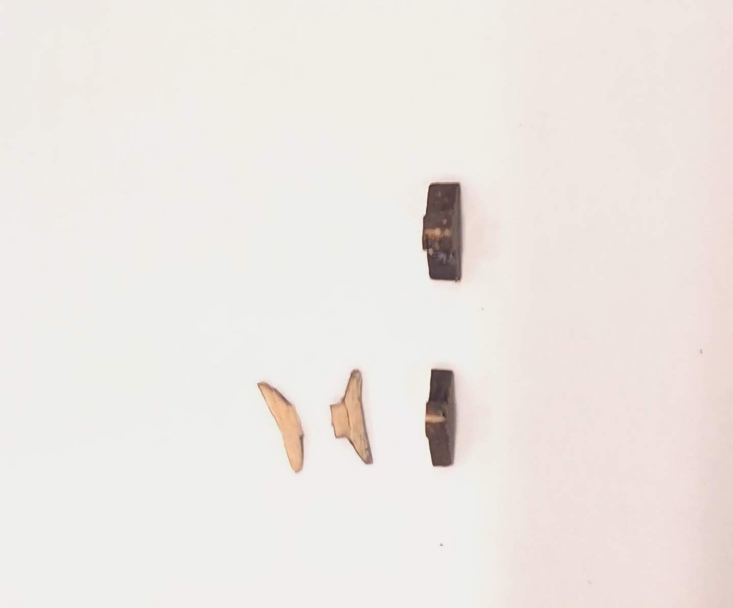
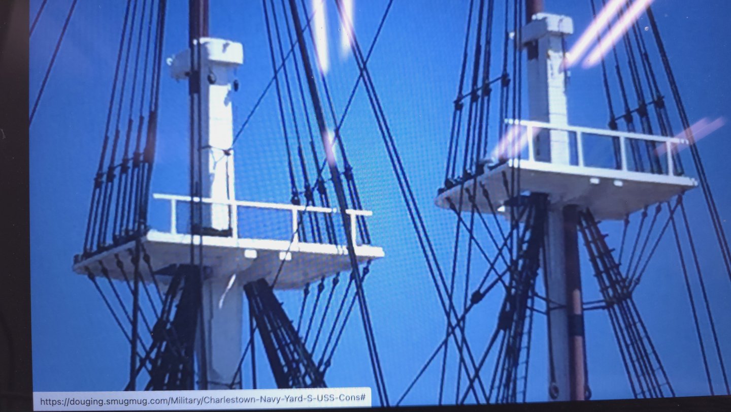
Thank you gentlemen, but I'm still not done. 🙄 The plans call for 1/32 inch square framework for the top guard rail. Even Ken doubled this to squeeze the netting in between. If I do this, I'm certainly not going to use the crappy Basswood that came with the kit. That is a disaster in the making. I can't remember exactly where I just got this photo, but the site purports to this being the post 1970ish refurbishment. Note the gaps between the guard rail and the fighting top. We're looking at the ends of the battens in the gap. But these views seem to contradict that, no? I have another couple of pictures to share. I did in fact install cleats. These were problematic because the ones I got from the Syren model ship company were too fat. So I trimmed them in super glued them into place. You know, as the guy who was always resisted this quest for super accurate rendering, I'm asking myself, Self, who are you, and what have you done with Peter? 😆 Jon, before I ash-can the rails altogether, I recall that you recommended netting of some kind for the head area to someone else. Do you recall that? If so what did you recommend?


-
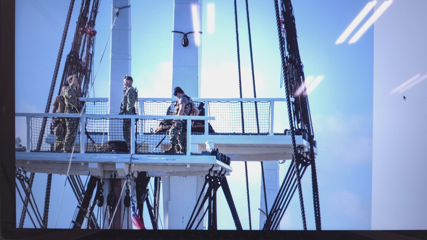
And to conclude the research/discussion on the fighting tops from post 1052 earlier on this page.. Thanks to XKen's build log, the answer to the question is "b", there are gaps between the battens beneath the guard rail base! Why? I have no idea. It actually seems pointless, especially if the ends are covered. .. as they appear to be with the trim piece Ken added around the perimeter in this photo. Let's call it artistic license?
-
I pored over XKen’s build log (per Gregg’s suggestion above), and saw the details on rigging the truss pendant. In those details, Ken notes that adding the trusses to an already secured yard was difficult, begging the question, what exactly is a truss pendant? My guess, based on Ken’s comments and the color of the line, is that this is running rigging, used to adjust the yard somehow. It is unclear to me in the plan snippet above what happens to the truss pendant where it disappears behind the triple block at the jeers. Thank the Lord for Ken’s documentation. The details on the plans are the pits! I went one step further. I checked Bob Hunt’s Rigging Practicum and found this in Chapter 6, beginning on page 5 (the Chapter on “ Running Rigging”). Evidently, Ken’s detailed explanation is an attempt to decipher Hunt’s instructions regarding the trusses. Here are Bob Hunt’s instructions: "The last part of rigging used to attach the yardarm to the mast is the truss. First seize a 1/8” single block to a piece of .021” tan line (all three masts). Another .021” tan line (all three masts) is seized to the block as a lanyard and will be carried upward to a 1/8” double block (all three masts) that is seized to an eyebolt on the aft underside of the mast cap. Use a figure eight type seizing to seize the 1/8” double block to the eyebolt first and then attach the eyebolt to the underside of the mast cap by drilling a small hole with your pin vise. The block is located on the aft underside, one on the port and one on the starboard side. The truss line with the 1/8” block in it comes down through the mast top on the starboard side of the trestle tree and wraps around the yard. This is where it gets a bit complicated. After it wraps around the yardarm, front to back, it has an eyelet seized in the end. On the port side, another truss with a 1/8” single block (all three masts) and lanyard comes down through the port side of the mast top and it wraps around the yard arm (on the port side), front to back. It passes through the starboard side truss eyelet and then doubles back to form an eyelet of its own around itself. Confused? Look at the drawing labeled Truss Lead on sheet 8 of your plans. To simplify things, you can first bring the starboard truss end down and around the yardarm and then around the back side of the mast where it will lead forward and under the yardarm on the port side, wrap around the yardarm once and the go up through the mast top on the port side by the trestle tree and end with another 1/8” single block and lanyard. If you make this line off of the ship and keep the distance between the first 1/8” block and the second 1/8” block at the other end at about 2” to 3”, it should fit just about right. If you look at the drawing labeled Lower Truss, Sling & Jeer Details, you’ll see that the truss’ actually pass along a sheave on the trestle trees that’s held in place by a block of wood. You can simulate this by cutting a small piece of .060” styrene that is 1/8” long and 3/32” wide. Round the aft corners of the styrene as you see in the drawing and use super glue to attach to the sides of the trestle trees with the truss line passing on the aft side of the part. The lanyard to the truss rigging is belayed to a cleat that is installed on the cross tree. The cleat is on the fore side of the lower cross tree. You can see this cleat in the drawing labeled Top Construction on sheet 6 of your plans. Actually I missed this cleat when I constructed the masts in chapter 1 and apologize for that. It may be a bit difficult to drill a hole for the cleat at this stage, but you can clip off the pin on the bottom of the cleat and use super glue to glue it to the fore side of the crosstree. Hold it with tweezers, put a drop of super glue on it and press it against the side of the crosstree holding it there for a few seconds to give the glue time to set. Allow the super glue to dry for 10 or 15 minutes before you try to belay the truss lanyard. You’ll also see that on the mast cap, the sling sits in a grooved piece of wood to help hold it in place. This can be simulated by gluing two strips of .030” square styrene on each side of the rope and making the styrene strips the same length as the mast cap is wide." I suppose I could get side tracked with the further research on this now, just in case I change my mind and include running rigging, or I could postpone the agony and just add the cleats. Thanks Mustafa, Gregg, Ken, and (even) Bob Hunt .
-
That's what I've been telling myself for about 2 years. Unfortunately, Geoff has been off the radar for quite a while. I'll be checking everyone's build logs - no more missing Ken's, but starting with our current front runner, Mustafa! 😁