
Der Alte Rentner
-
Posts
1,041 -
Joined
-
Last visited
Content Type
Profiles
Forums
Gallery
Events
Everything posted by Der Alte Rentner
-
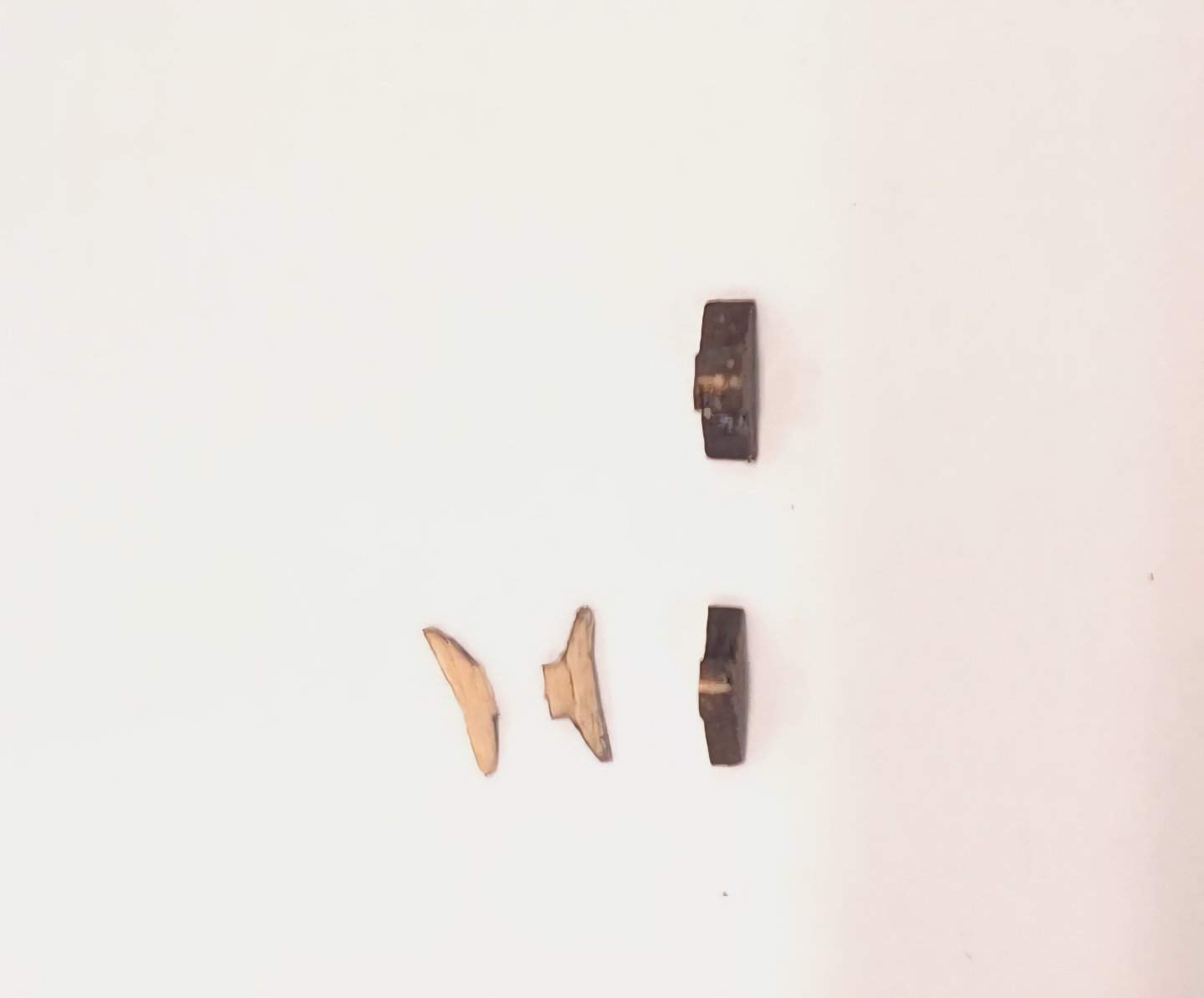
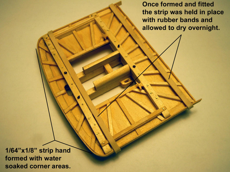
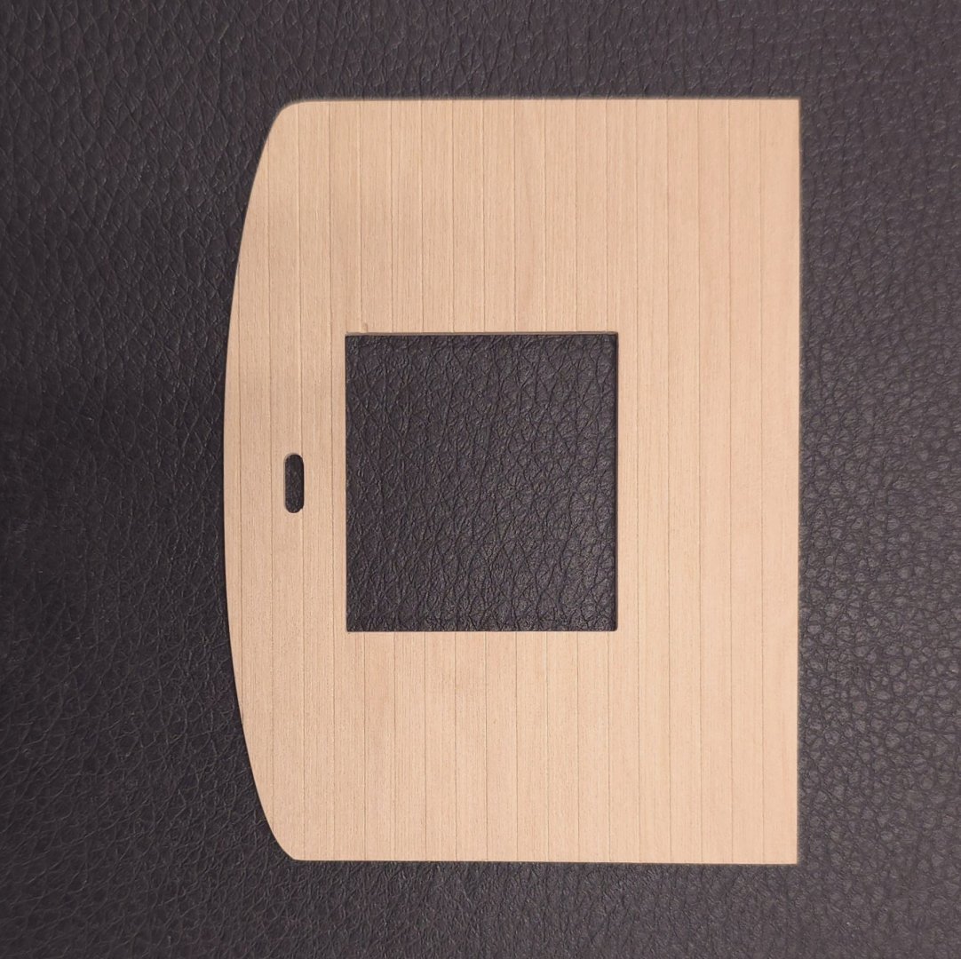
 For what it's worth, the 1/64" thick sapele wood strips I used, which came with the Constructo Constitution kit - in case you missed that nugget of information, bent quite easily. I put a length of this into a pot of water and let it simmer a while before wrapping it around the corners. The hardest part was getting rubber bands or clamps on to hold the strip secure while the Titebond glue dried. It wouldn't bend to a hard 90 degrees without splitting. So, for the back edge of the top, I simply fitted a straight segment of sapele and butt jointed it to the bent piece.
 -
USS Constitution by mtbediz - 1:76
Der Alte Rentner replied to mtbediz's topic in - Build logs for subjects built 1751 - 1800
While you're still on R&R, could you put some thought into recommending some work that I could take with me on my upcoming R&R trip (starting Saturday). You know that I'm wrapping up the fighting tops on my build, but I won't be taking my mill with me. I also didn't have time to order (or make) a serving machine. That surely limits the options. Still, I'm thinking there will be many blocks to strop. Can you suggest where I focus my priorities for doing that while gone? I would sincerely appreciate it. Thanks -
Not as fragile as the basswood that came with the kit. I made my own 1/32" square boxwood stock. Still, your idea to substitute brass for the stanchions is intriguing! I will seek out some of that material and experiment with it. There's no rush. since I'm firmly committed to holding off on adding the rails to the tops until after the rigging is done. Thanks for an excellent suggestion.
-
Unless the cleats are brass, switching to metal would go against my color scheme. In this case, the material didn't matter as much as the size. If you've got brass cleats that are 1/32" wide, I'd like to know where you got them.
-
As an aside, can someone explain to me why the formatting of these posts displays differently on a desktop versus on a phone? In a couple of my previous posts, I set the text up to be on the right side of the photos. The post looked exactly the way I wanted it to on my desktop, but when viewed on my phone, the text ends up above or below the photos - and there are huge gaps between photos and text. I think going forward, I will resist the urge to get fancy with photo and text placement in these posts.
-
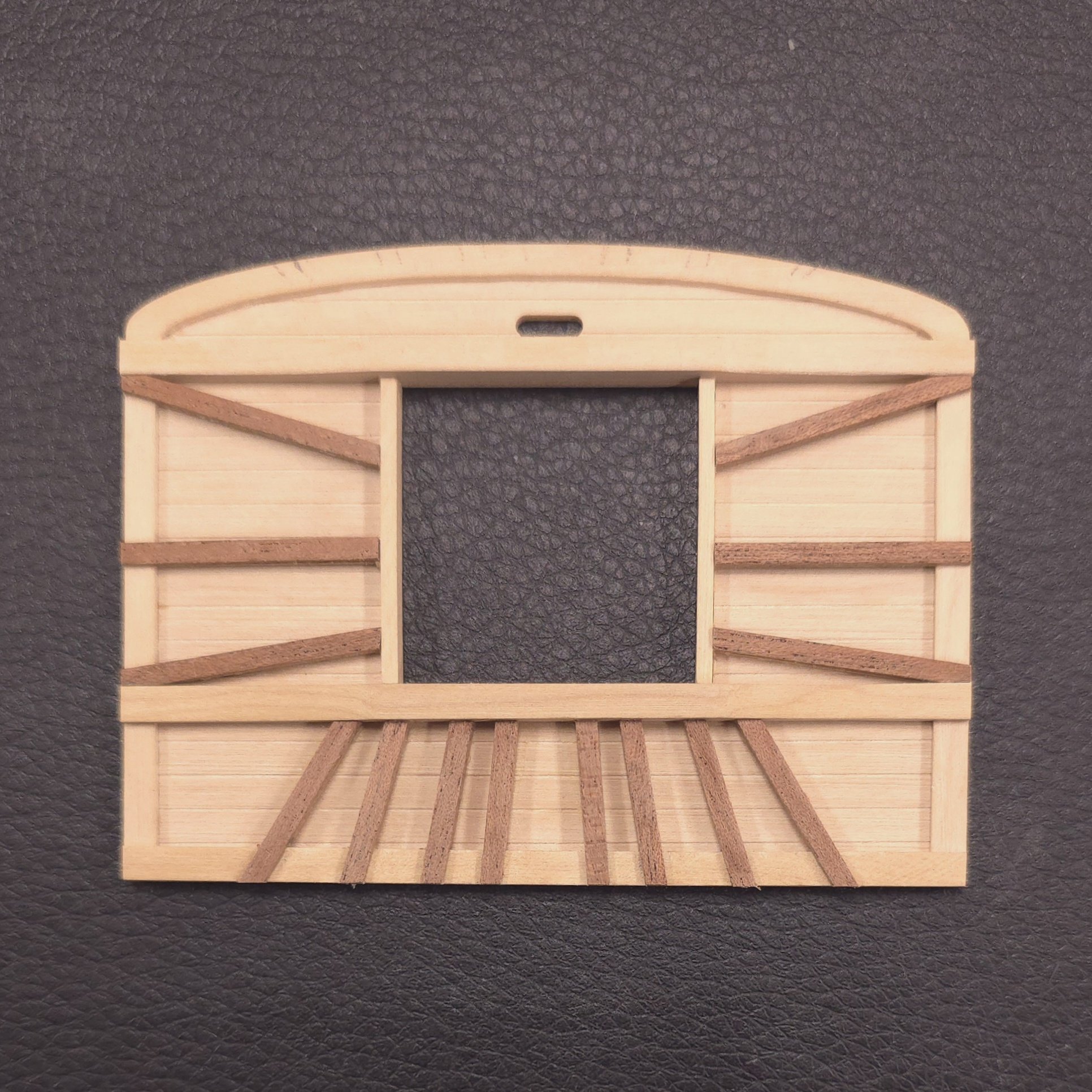
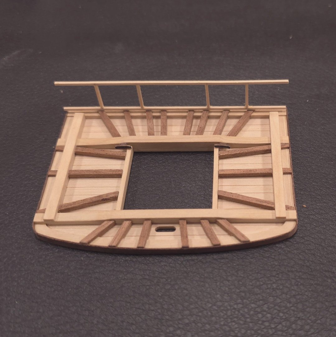
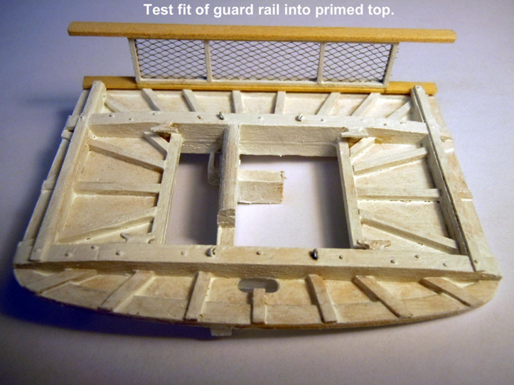
Analysis paralysis is over. I've taken a position. While I am not yet 100% sure I will be adding the top rail, which is right now only dry fitted on the battens, I'm happy with the look of the top itself. As flimsy as the top rail construction is - 1/32" square boxwood per the plan, I can't possibly consider fixing it in place permanently until I've come up with an arrangement like Ken did, where I can easily locate it and glue it after all the rigging is done. I could add some pins at the bottom or mill a 1/32" wide slot into the battens to press fit the bottom board into. Frankly, I've seen models without a top rail, and I'm perfectly happy to live without one. And before anyone asks, no, I will not be messing around with netting. The edge banding went very well. Stay warm out there this weekend.
-
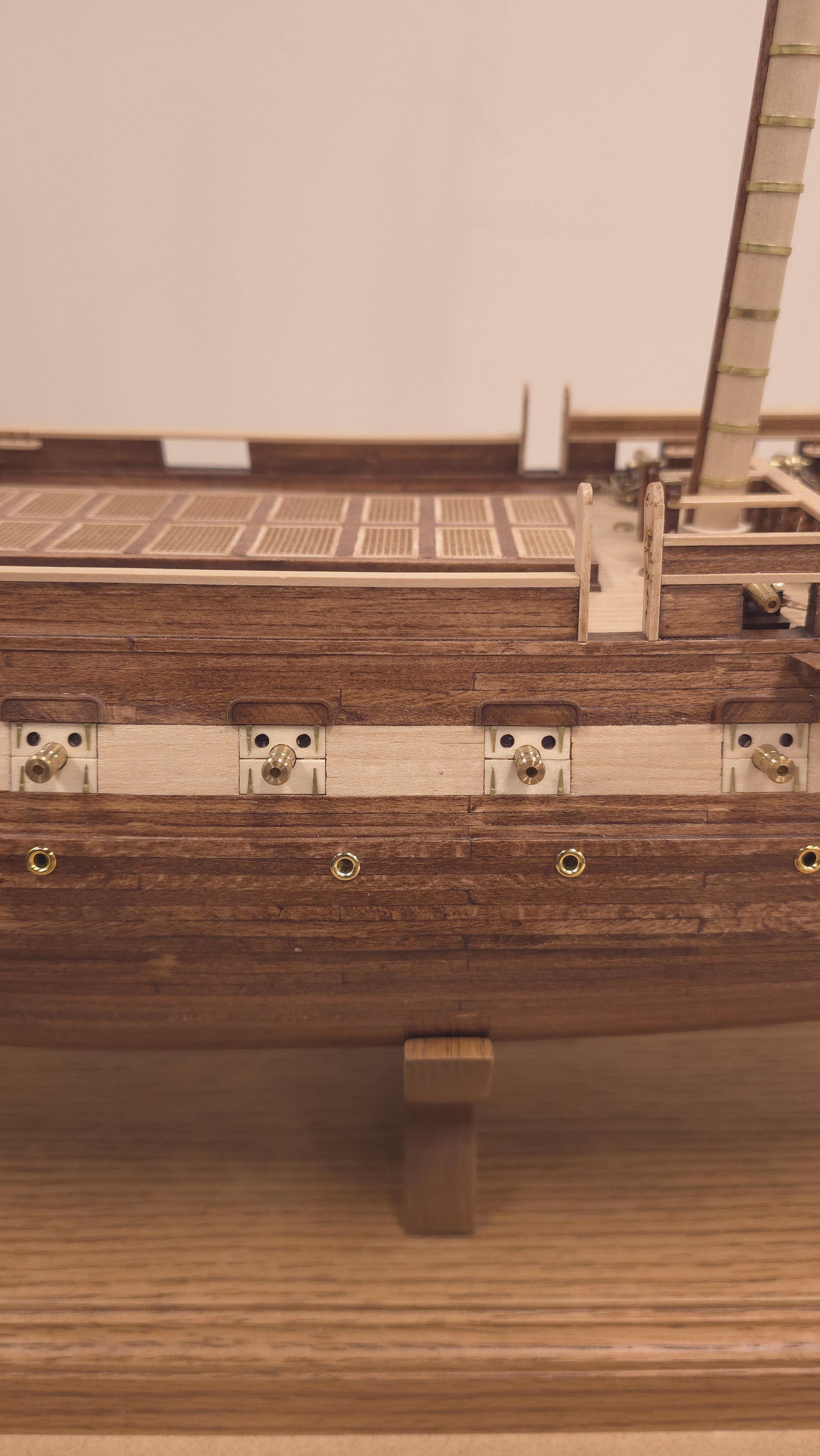
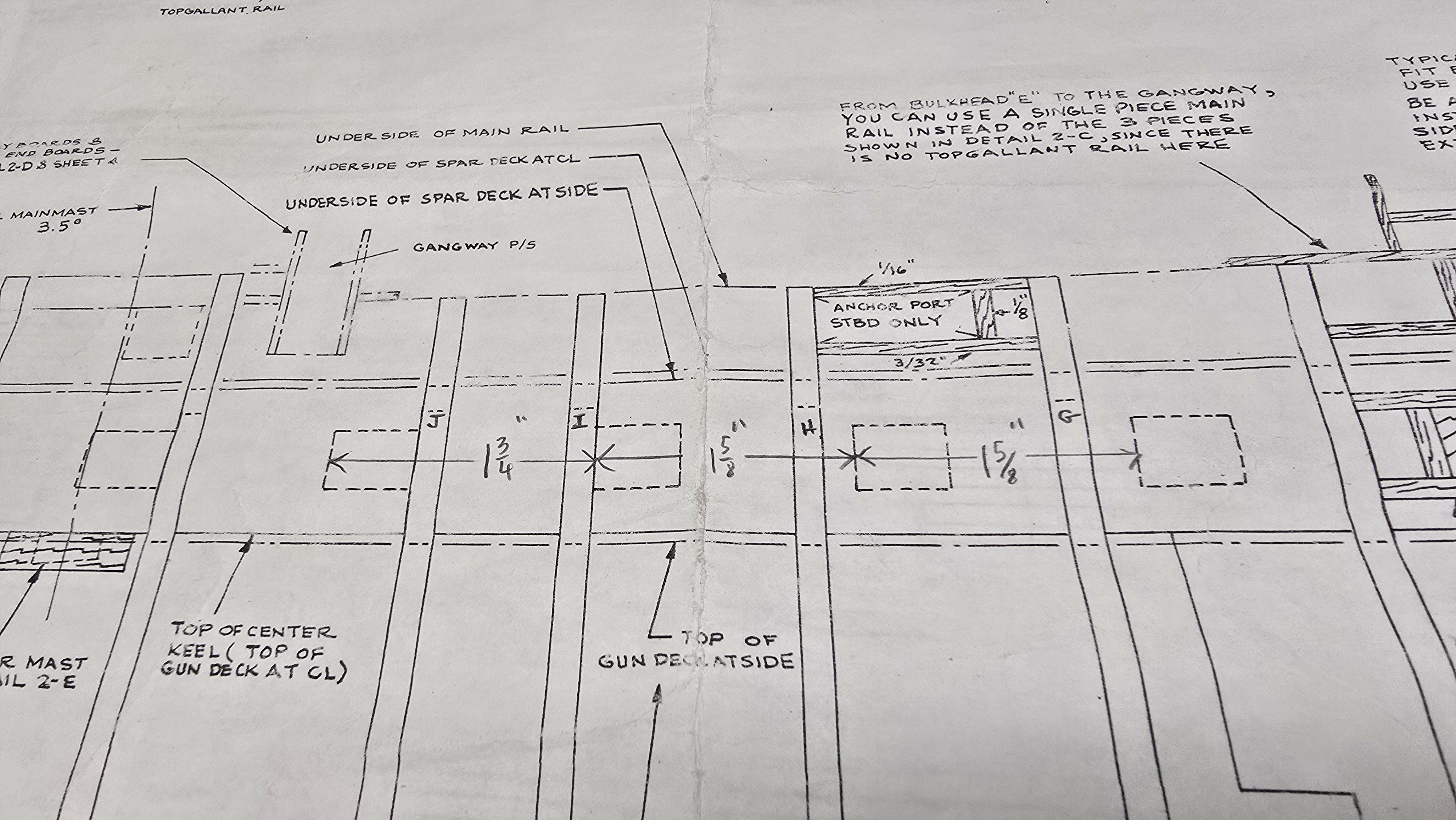
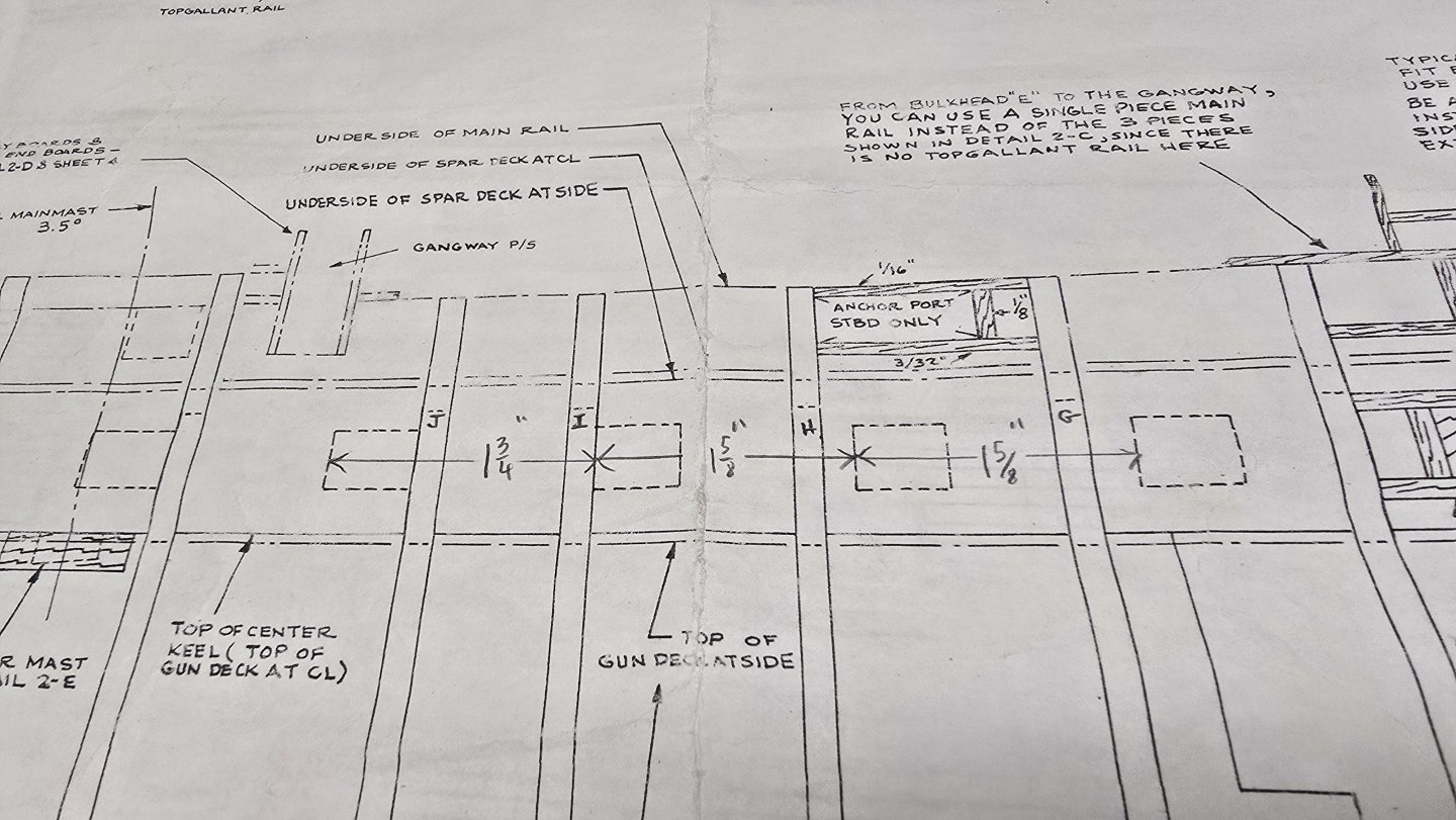
If there's no room up against the extension, you're going to have to compensate by moving the gun, understanding that it's not just a question of the gun - you also have to concern yourself with the location of the gunport lids. If moving the gunport lids 1/8" one way or the other doesn't impact anything else, which seems to be the case for the one in question, make the move. The plans show that the spacing isn't 100% even between the ports anyway. Check the measurements on the plans below. Hope that helps.

-
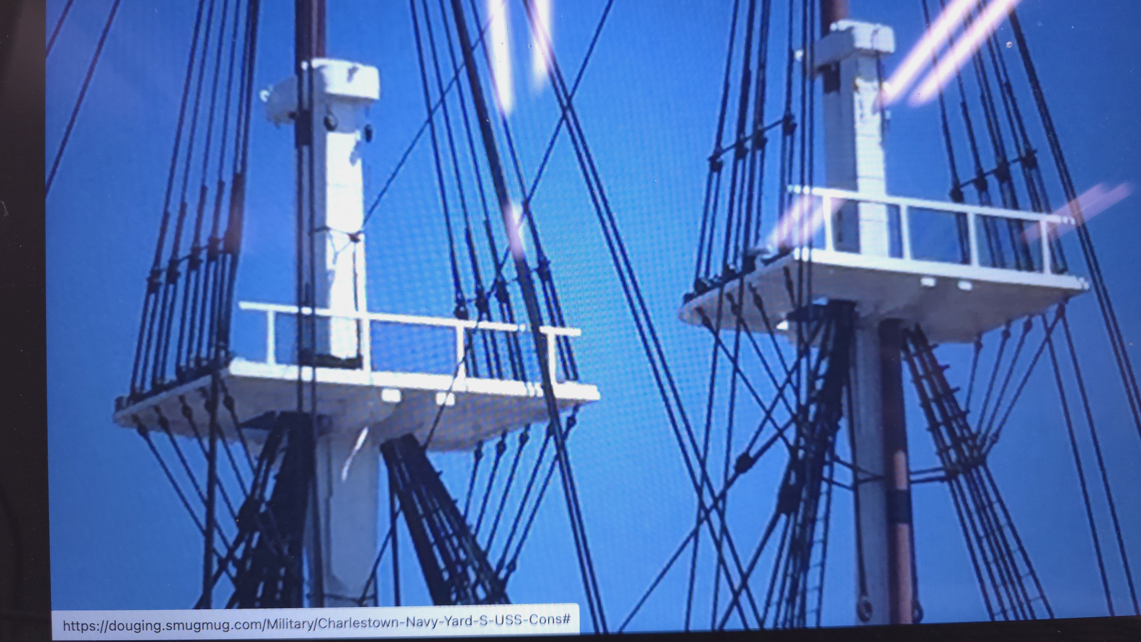
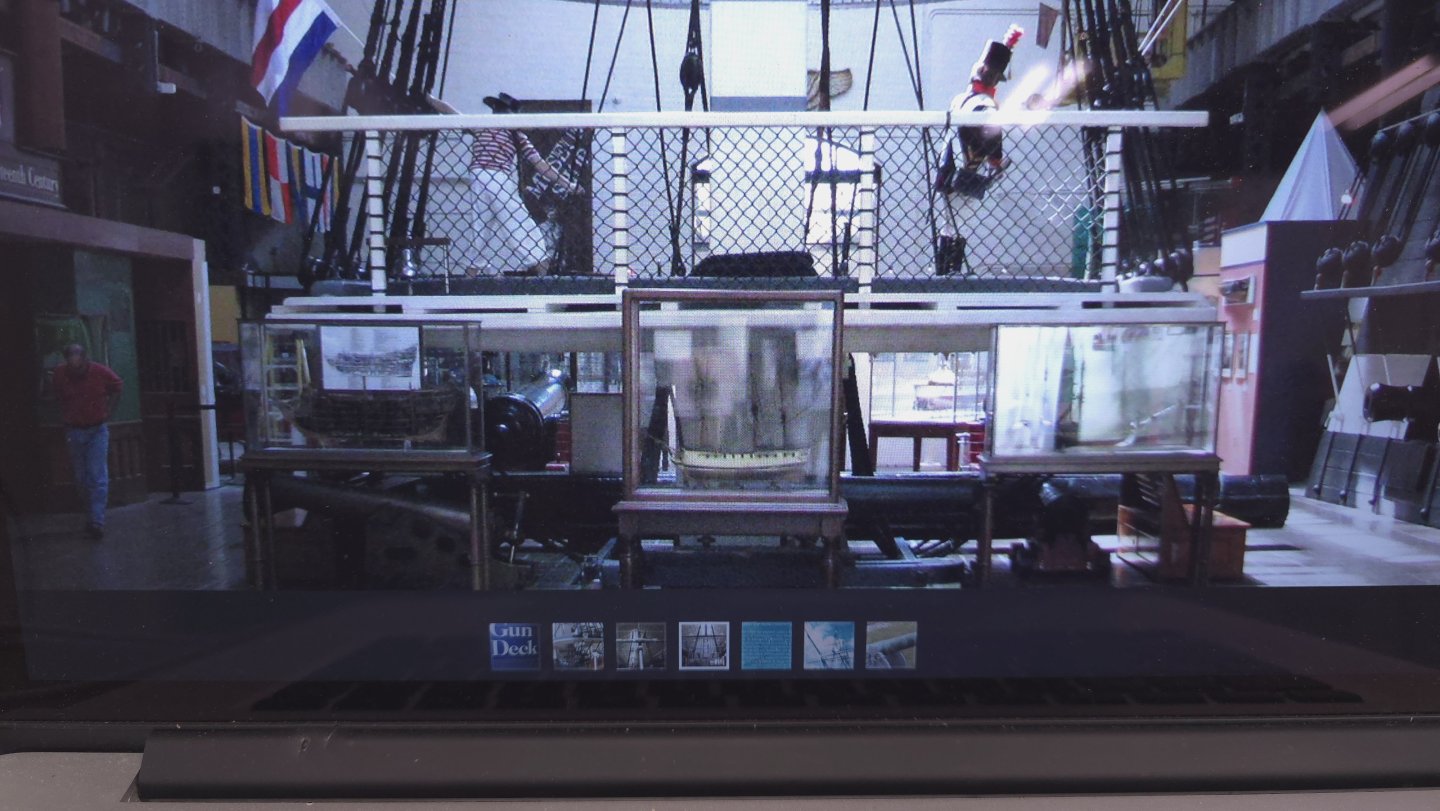
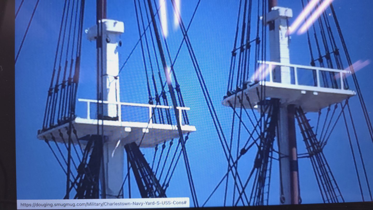
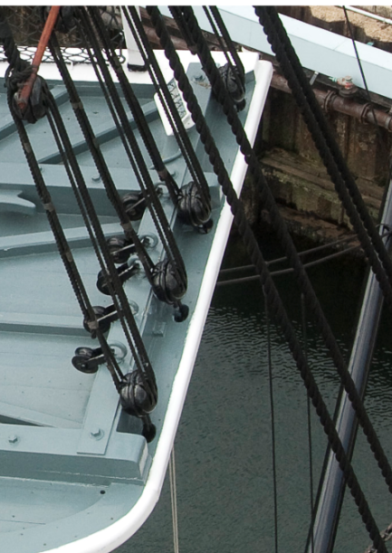
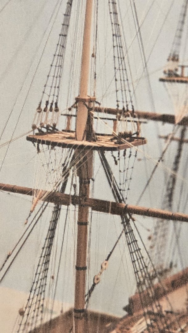
Thank you gentlemen, but I'm still not done. 🙄 The plans call for 1/32 inch square framework for the top guard rail. Even Ken doubled this to squeeze the netting in between. If I do this, I'm certainly not going to use the crappy Basswood that came with the kit. That is a disaster in the making. I can't remember exactly where I just got this photo, but the site purports to this being the post 1970ish refurbishment. Note the gaps between the guard rail and the fighting top. We're looking at the ends of the battens in the gap. But these views seem to contradict that, no? I have another couple of pictures to share. I did in fact install cleats. These were problematic because the ones I got from the Syren model ship company were too fat. So I trimmed them in super glued them into place. You know, as the guy who was always resisted this quest for super accurate rendering, I'm asking myself, Self, who are you, and what have you done with Peter? 😆 Jon, before I ash-can the rails altogether, I recall that you recommended netting of some kind for the head area to someone else. Do you recall that? If so what did you recommend?


-
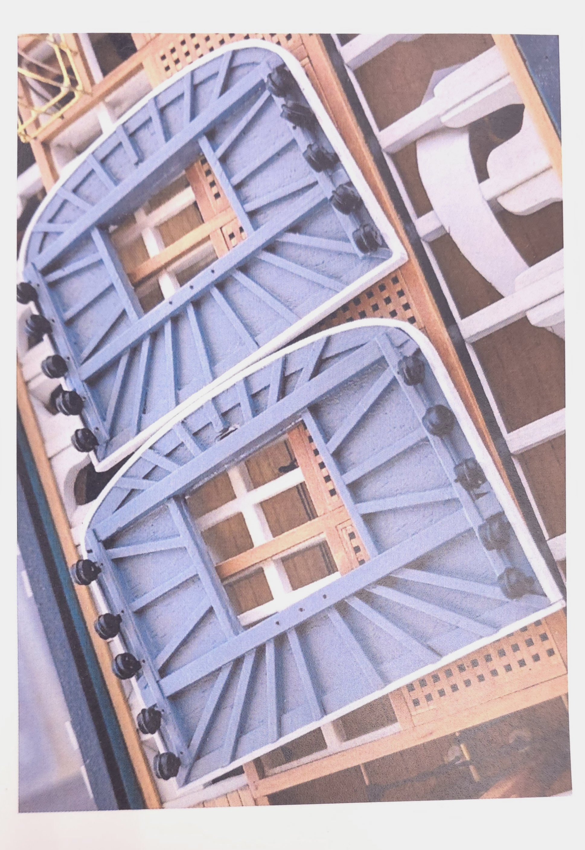
And to conclude the research/discussion on the fighting tops from post 1052 earlier on this page.. Thanks to XKen's build log, the answer to the question is "b", there are gaps between the battens beneath the guard rail base! Why? I have no idea. It actually seems pointless, especially if the ends are covered. .. as they appear to be with the trim piece Ken added around the perimeter in this photo. Let's call it artistic license?
-
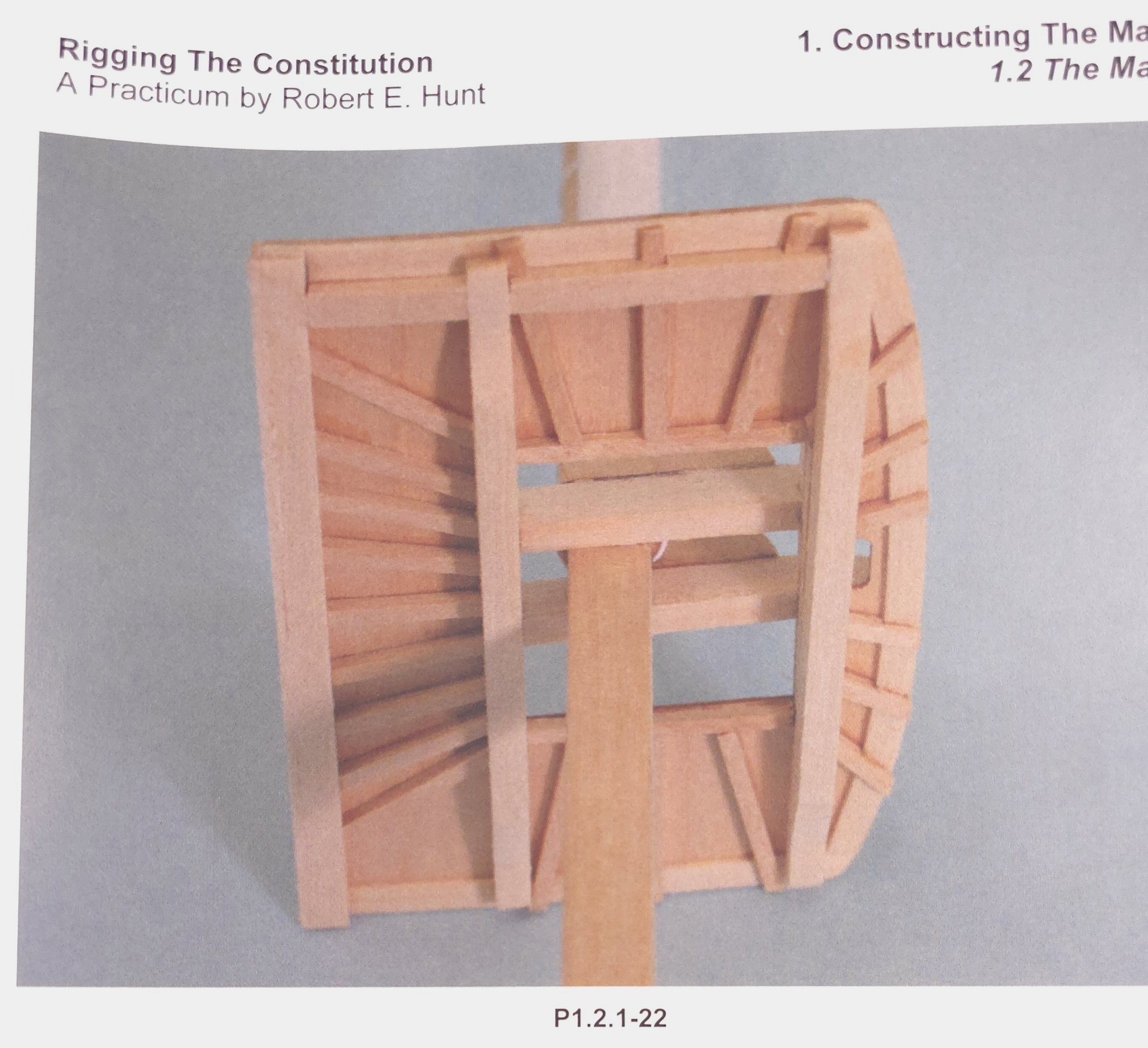
I pored over XKen’s build log (per Gregg’s suggestion above), and saw the details on rigging the truss pendant. In those details, Ken notes that adding the trusses to an already secured yard was difficult, begging the question, what exactly is a truss pendant? My guess, based on Ken’s comments and the color of the line, is that this is running rigging, used to adjust the yard somehow. It is unclear to me in the plan snippet above what happens to the truss pendant where it disappears behind the triple block at the jeers. Thank the Lord for Ken’s documentation. The details on the plans are the pits! I went one step further. I checked Bob Hunt’s Rigging Practicum and found this in Chapter 6, beginning on page 5 (the Chapter on “ Running Rigging”). Evidently, Ken’s detailed explanation is an attempt to decipher Hunt’s instructions regarding the trusses. Here are Bob Hunt’s instructions: "The last part of rigging used to attach the yardarm to the mast is the truss. First seize a 1/8” single block to a piece of .021” tan line (all three masts). Another .021” tan line (all three masts) is seized to the block as a lanyard and will be carried upward to a 1/8” double block (all three masts) that is seized to an eyebolt on the aft underside of the mast cap. Use a figure eight type seizing to seize the 1/8” double block to the eyebolt first and then attach the eyebolt to the underside of the mast cap by drilling a small hole with your pin vise. The block is located on the aft underside, one on the port and one on the starboard side. The truss line with the 1/8” block in it comes down through the mast top on the starboard side of the trestle tree and wraps around the yard. This is where it gets a bit complicated. After it wraps around the yardarm, front to back, it has an eyelet seized in the end. On the port side, another truss with a 1/8” single block (all three masts) and lanyard comes down through the port side of the mast top and it wraps around the yard arm (on the port side), front to back. It passes through the starboard side truss eyelet and then doubles back to form an eyelet of its own around itself. Confused? Look at the drawing labeled Truss Lead on sheet 8 of your plans. To simplify things, you can first bring the starboard truss end down and around the yardarm and then around the back side of the mast where it will lead forward and under the yardarm on the port side, wrap around the yardarm once and the go up through the mast top on the port side by the trestle tree and end with another 1/8” single block and lanyard. If you make this line off of the ship and keep the distance between the first 1/8” block and the second 1/8” block at the other end at about 2” to 3”, it should fit just about right. If you look at the drawing labeled Lower Truss, Sling & Jeer Details, you’ll see that the truss’ actually pass along a sheave on the trestle trees that’s held in place by a block of wood. You can simulate this by cutting a small piece of .060” styrene that is 1/8” long and 3/32” wide. Round the aft corners of the styrene as you see in the drawing and use super glue to attach to the sides of the trestle trees with the truss line passing on the aft side of the part. The lanyard to the truss rigging is belayed to a cleat that is installed on the cross tree. The cleat is on the fore side of the lower cross tree. You can see this cleat in the drawing labeled Top Construction on sheet 6 of your plans. Actually I missed this cleat when I constructed the masts in chapter 1 and apologize for that. It may be a bit difficult to drill a hole for the cleat at this stage, but you can clip off the pin on the bottom of the cleat and use super glue to glue it to the fore side of the crosstree. Hold it with tweezers, put a drop of super glue on it and press it against the side of the crosstree holding it there for a few seconds to give the glue time to set. Allow the super glue to dry for 10 or 15 minutes before you try to belay the truss lanyard. You’ll also see that on the mast cap, the sling sits in a grooved piece of wood to help hold it in place. This can be simulated by gluing two strips of .030” square styrene on each side of the rope and making the styrene strips the same length as the mast cap is wide." I suppose I could get side tracked with the further research on this now, just in case I change my mind and include running rigging, or I could postpone the agony and just add the cleats. Thanks Mustafa, Gregg, Ken, and (even) Bob Hunt .
-
That's what I've been telling myself for about 2 years. Unfortunately, Geoff has been off the radar for quite a while. I'll be checking everyone's build logs - no more missing Ken's, but starting with our current front runner, Mustafa! 😁
-
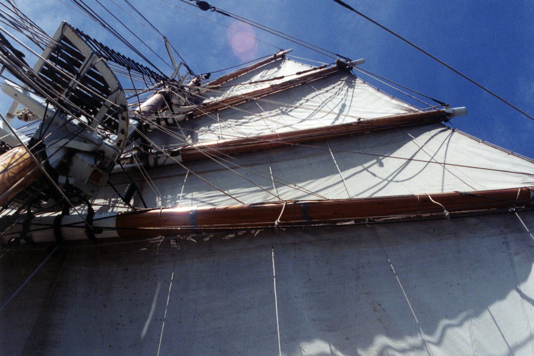
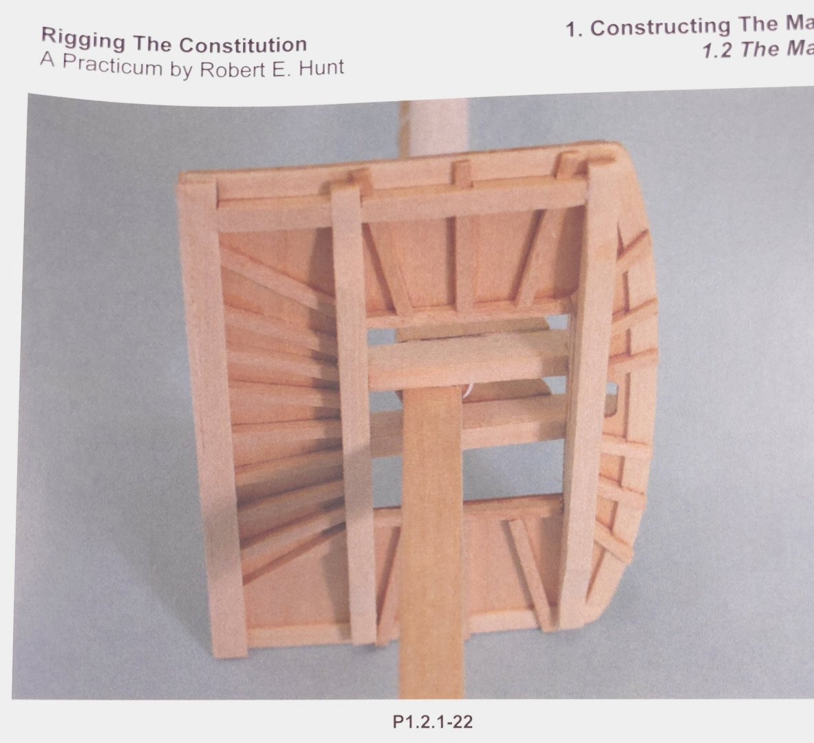
Because a new page was generated here at MSW, I'm supplying these photos on the new page to have them handy for discussion. This is the photo from XKen's build that Mustafa so kindly provided on the last page. This is one of Mustafa's tops. Remember that he said he would be installing the top rails later in the build, explaining why the foundations for them are missing here. This one is from the Hunt Practicum. And this is where I left off yesterday. (Note the bottom cross piece is not installed, only resting on the battens) And to complete(?) the picture, and at the same time - muddy the waters.. Here's a photo cribbed from one of Jon's posts. Note that the battens do not extend all the way to the rim on present day(?) Conny. If they did, I suspect there would be filler in the gaps. One more reference: Marquardt - lending credence to Mustafa's and XKen's choice for the battens. Note: This is one confusing drawing. If this is the top view of the fighting top, then the direction of the planking is opposite what appears on the present-day Constitution. Also, this would suggest that the battens do not extend to the rim at the aft end. Things I'm wondering about.. I got the placement for my battens from the plans that came with the Model Shipway's kit. Bob Hunt obviously referenced the same plans. However, Mustafa and Xken have a different numbers and orientations for theirs. The assumption is that they, as often happens at MSW, are referencing different plans from different eras. I can live with that. I noticed that my cross trees, the dimensions for which I thought I got from the Hunt practicum, are not as thick (or tall?) as the others. My only concern here, is for the cleats on the cross trees above. To any of you who have already rigged the Constitution, are these cleats necessary for standing rigging? I don't plan to deploy running rigging, so if these are not necessary, I may just omit them. Otherwise, I'll likely be adding material to these two cross trees. Lastly, I'm wondering which is the case: a) There is filler between the battens underneath the stern-most cross tree (foundation for the top rail). On the photos from the present day Constitution, this seems to be the case. (By the way, I did put filler between the six battens on the port and starboard sides, because the outboard ends are clearly visible. I didn't think about leaving gaps there until today). b) There are gaps between the planking and the cross tree. c) The battens butt against the edge of the cross tree. My guess is option b. If it were option a, then no one would have bothered to have the battens extend to the very edge of the top itself, because the same end could be accomplished by option c. As such, when I do return to the shipyard, I'll trim the thickness of my cross tree and glue it on top of the battens. Though, it would be easier to lop the ends off the battens - not so much for the main top, but so that making the mizzen and fore tops would be easier. The effort to make the dados could be eliminated. So much for the donut deprived slacker this Thursday.


-
Well, well, well! Thanks for chiming in with that interesting nugget of information, Mustafa. That settles it for me then - and makes my life easier. Now I don't have to form that dado at the end of most of the battens for the other two tops. Nevertheless, given that I just washed my truck yesterday - of course this prompted the snow storm overnight, and being reluctant to get salt back on it with the drive to the shipyard today, I'll take another day or two to ponder why there's only one guard rail on each of the tops. And, to answer Gregg 's question, you might be better off asking Geoff Matson about the quality of the rigging portion of the Hunt practicum. From what I gather, the rigging portion of the practicum is text heavy and picture light. The very last chapter is all text - no pictures, and there's not a single photo of the Constitution with the rigging anywhere in the practicum. I've been counting on Geoff to deliver the goods on this front. Finally, how on earth did I fail to consult Xken's build log for this? (P.S. this is something that may probably only resonate with Geoff. I'm mourning the loss of my beloved Riverside Bake Shop in McHenry, IL. I had what may have been my very last chocolate iced cake donut Sunday morning. The bakery burnt down Sunday afternoon. I'm absolutely devastated.)
-
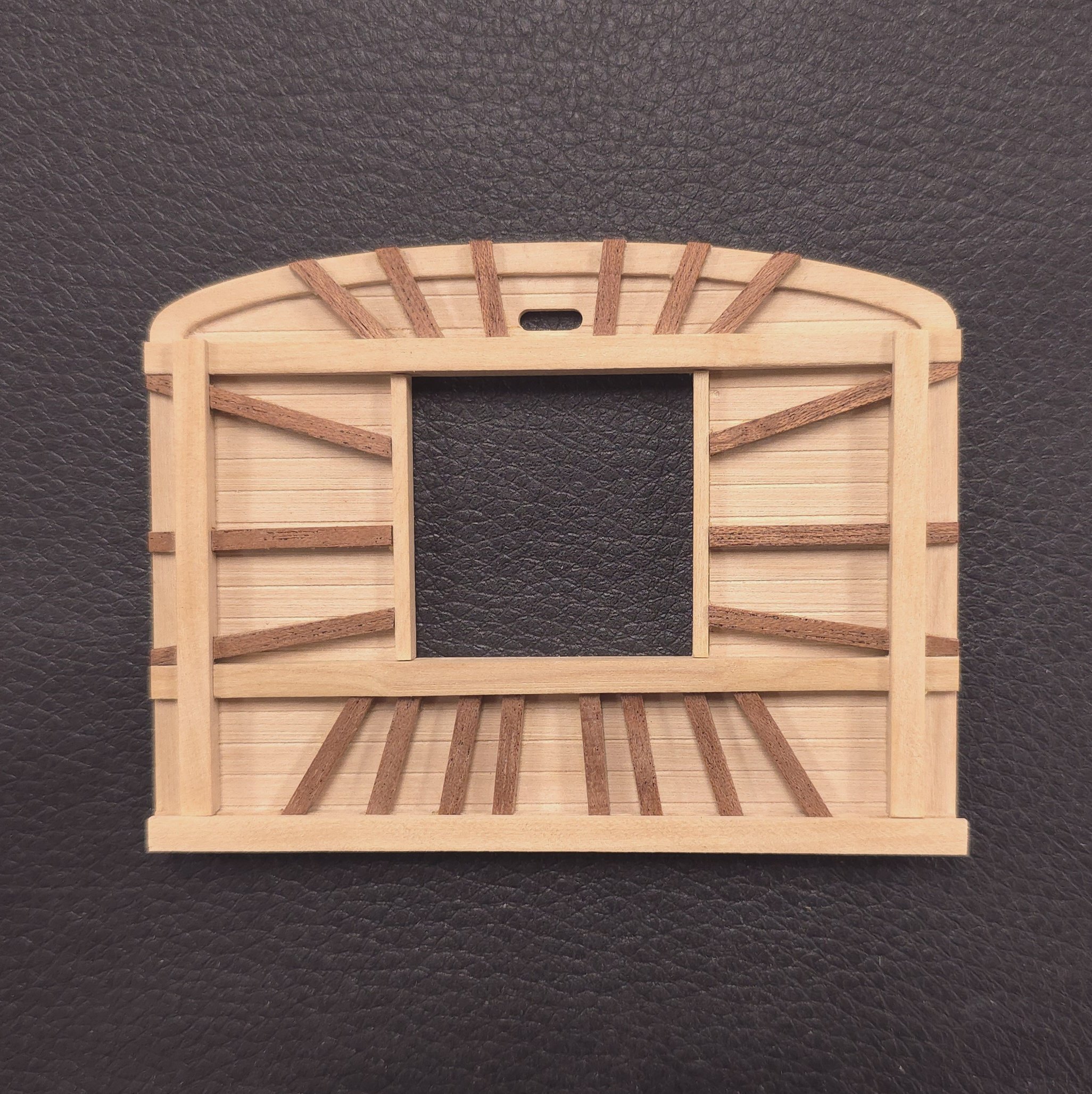
Thank you everyone for your kind words and positive feedback. It really means a lot to me, and motivates me to do my absolute best moving forward. Today was another nearly full day at the shipyard, and I still couldn't pull the trigger on the final version of the main fighting top. Maybe I shouldn't have too many photos of other people's builds lying about my workbench. They can contribute to analysis paralysis. I really liked the approach that Mustafa took with his fighting tops, with the battens running all the way to the trim around the rim, and sort of modeled mine after his. Let's call that concept A. But then I've got Bob Hunt's practicum, the photos of the actual fighting top on the Constitution, and at least two other contributors who fall more-or-less into concept B. In this version, there's a trailing edge that covers the battens at the aft end, where the stanchions for the top rail are mounted. After all the effort I put into getting those battens to look as good as they do, I'm reluctant to cover then or simply cut the ends off. So I'm posting this and giving it the night to decide whether or not I'm going to add the top rail.
-
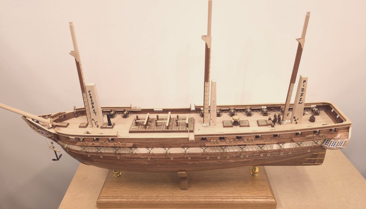
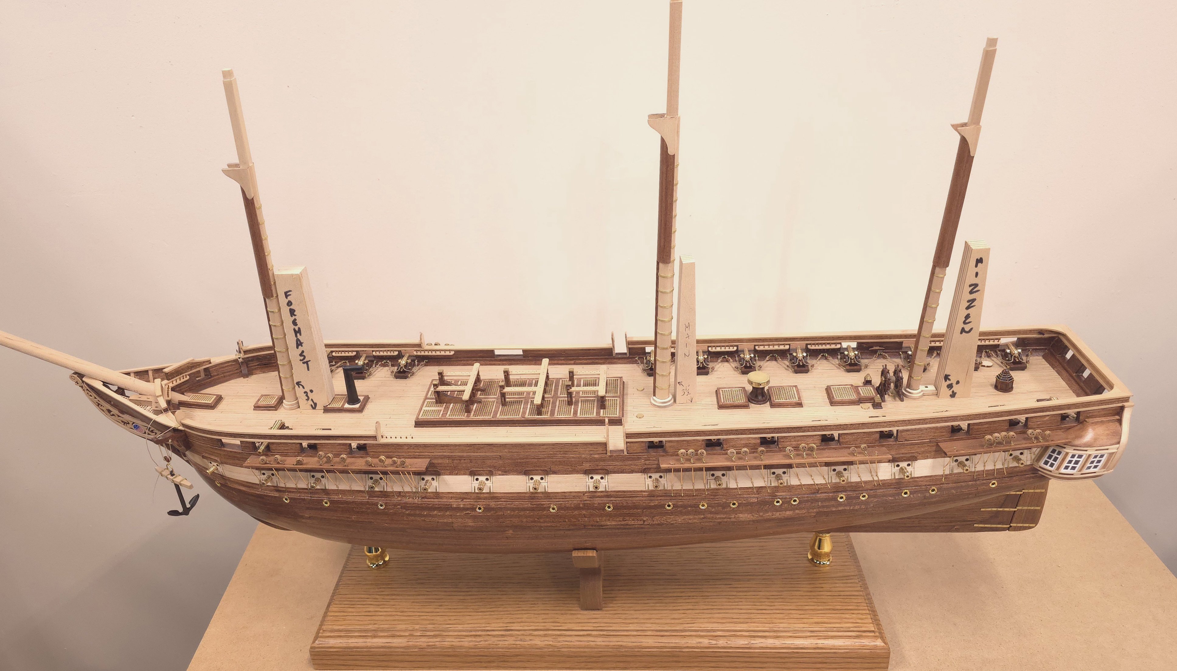
It came with the Constructo kit of the USS Constitution that I bought but never built. I switched to the Model Shipways kit after learning of this website and discovering the wealth of information available for the Model Shipways kit here. Kudos to Hipexec for posting a build log on the Constructo kit. It was the look of his finished product that inspired me to drop the black and white scheme everybody else employees on Connie.
-
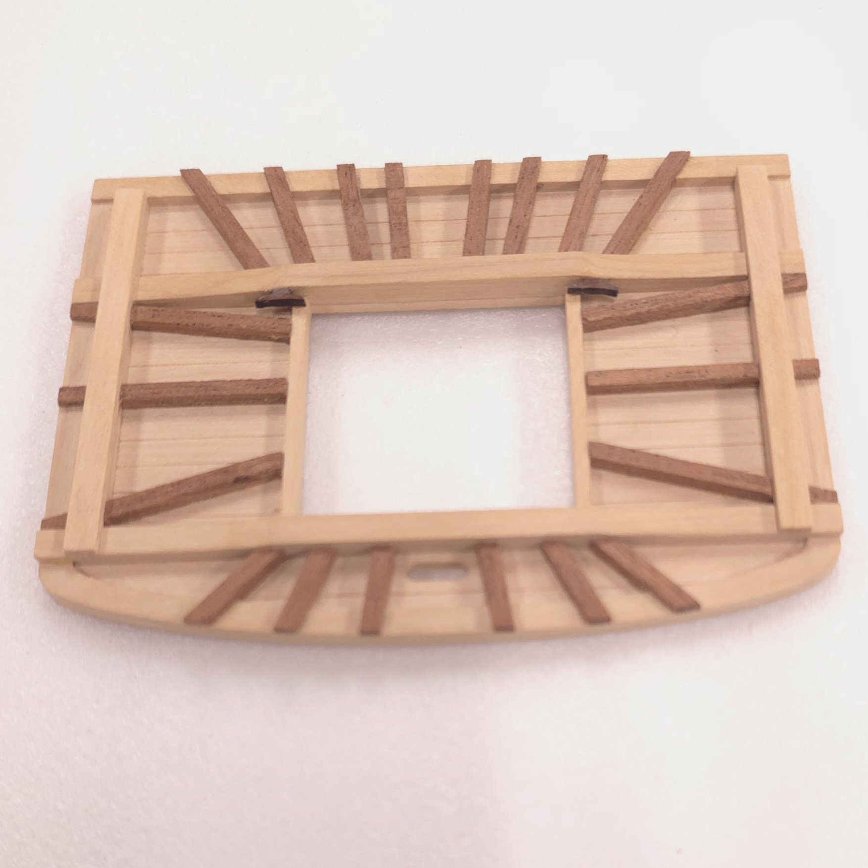
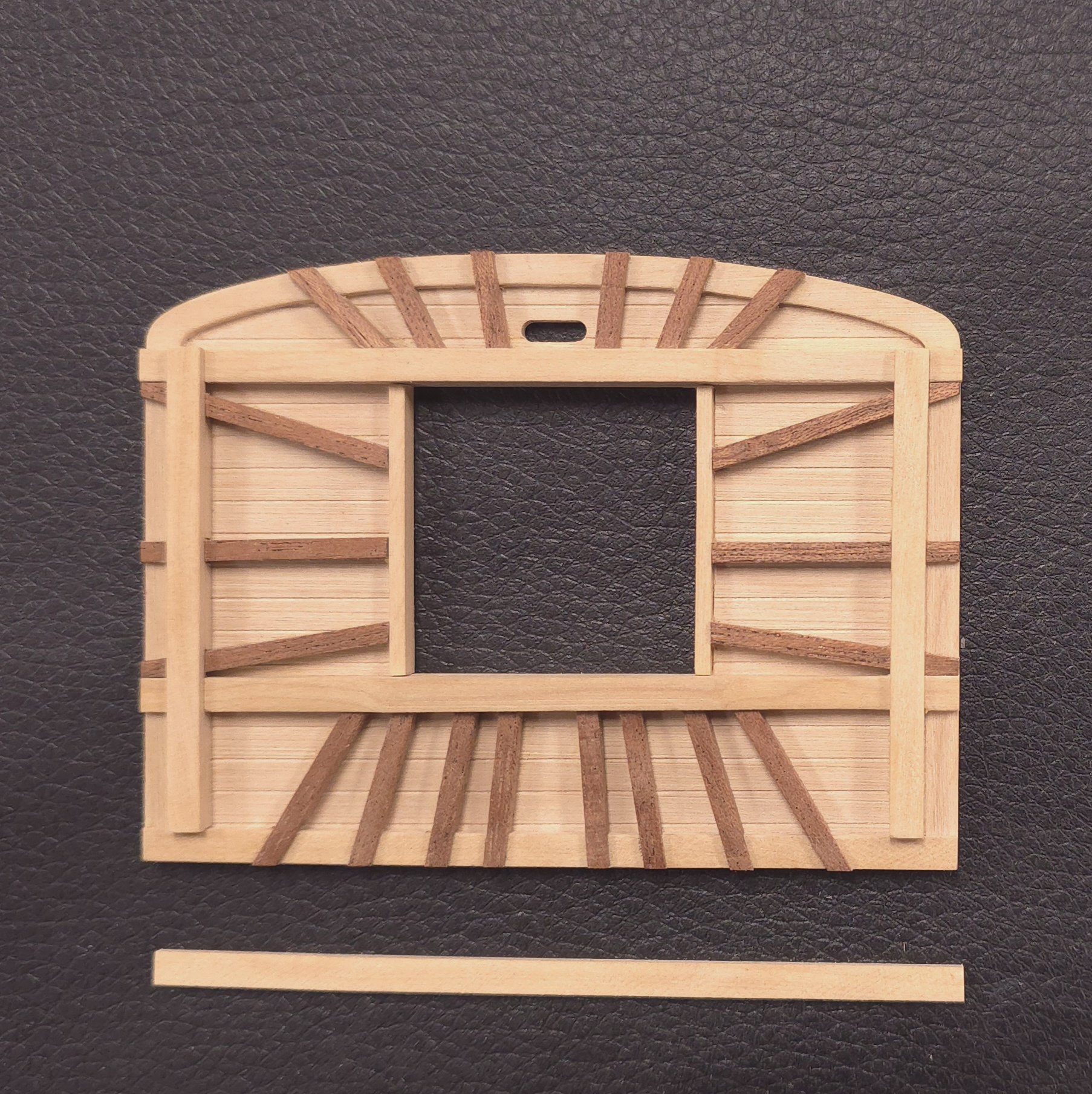
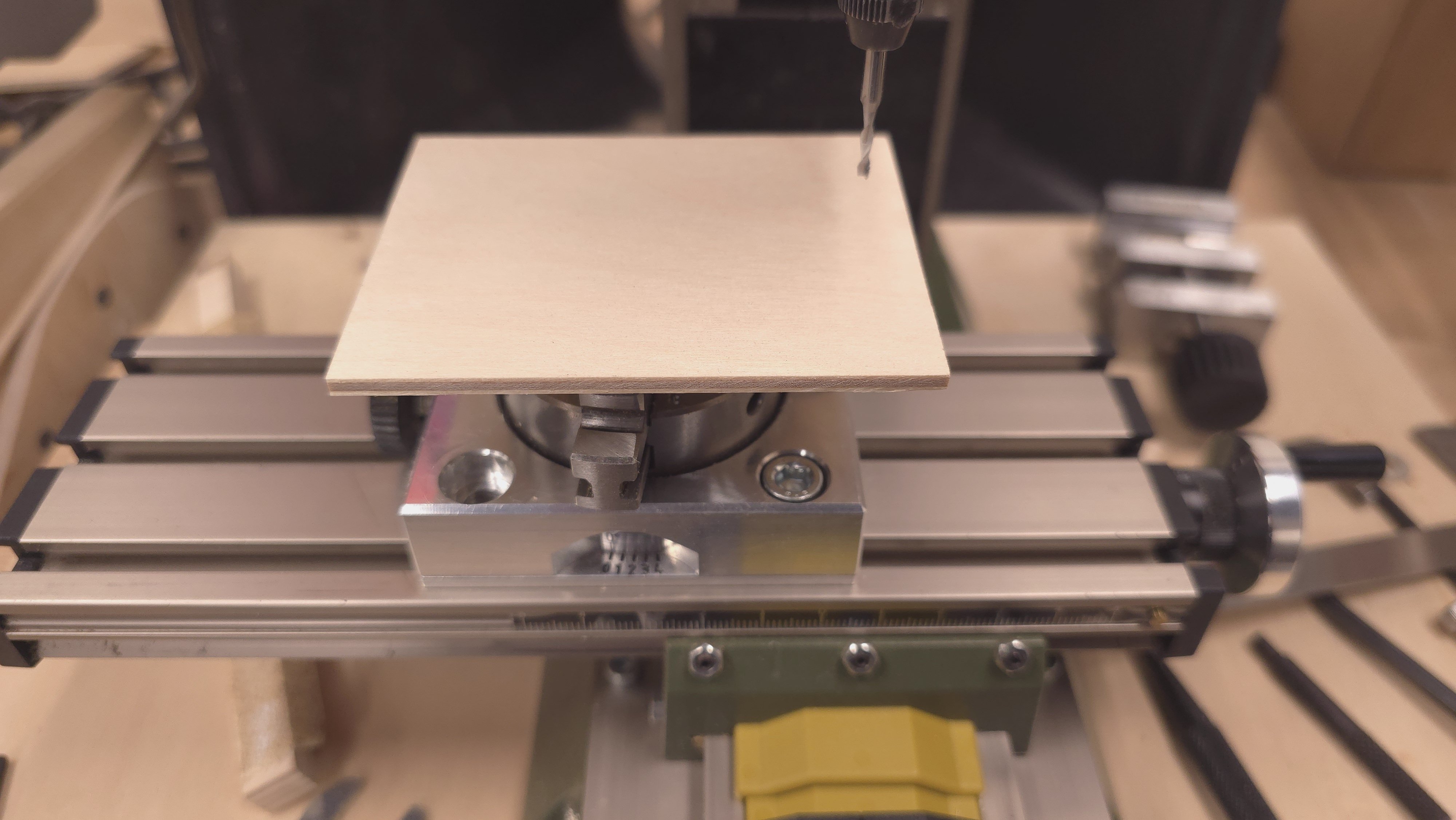
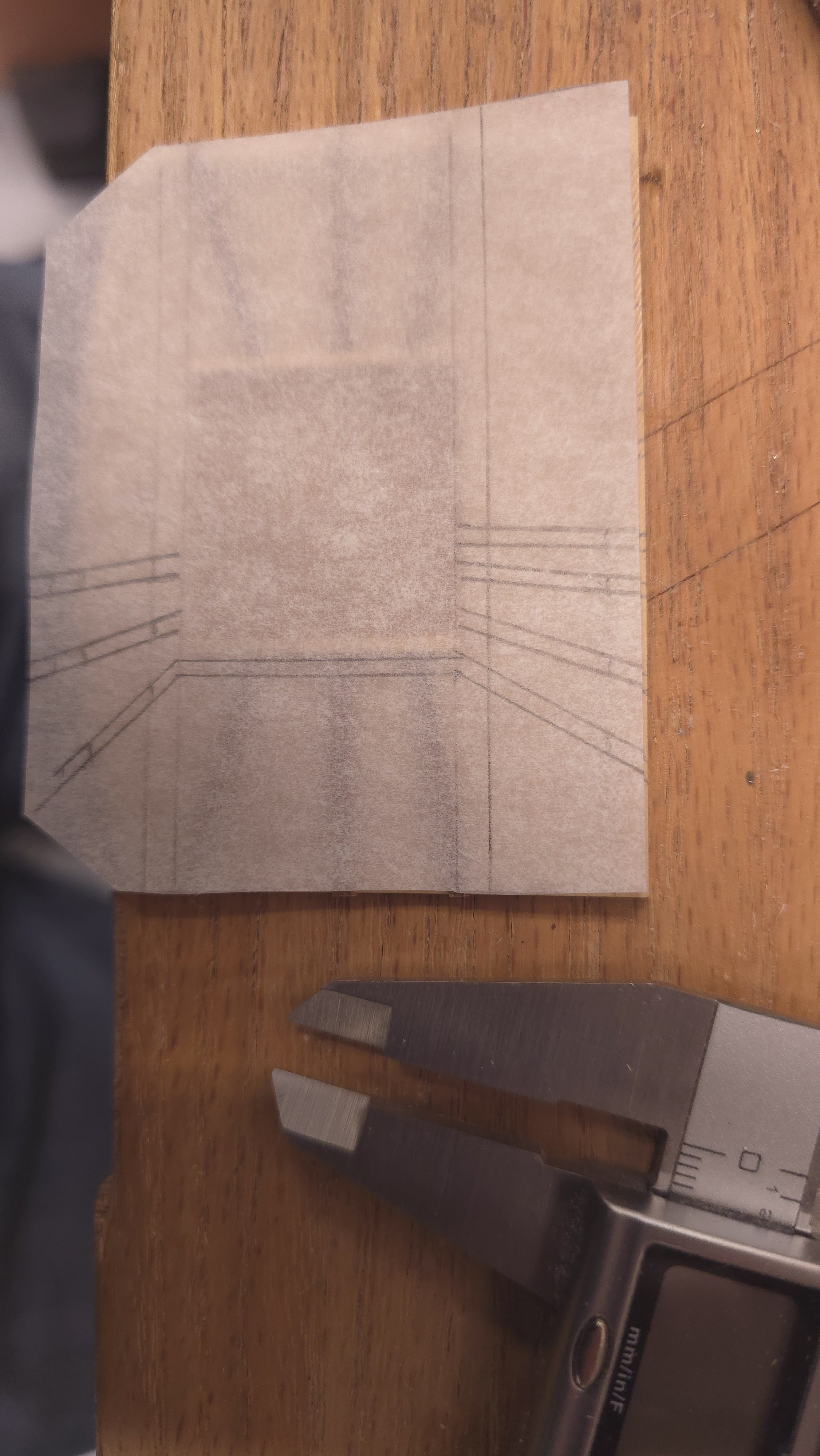
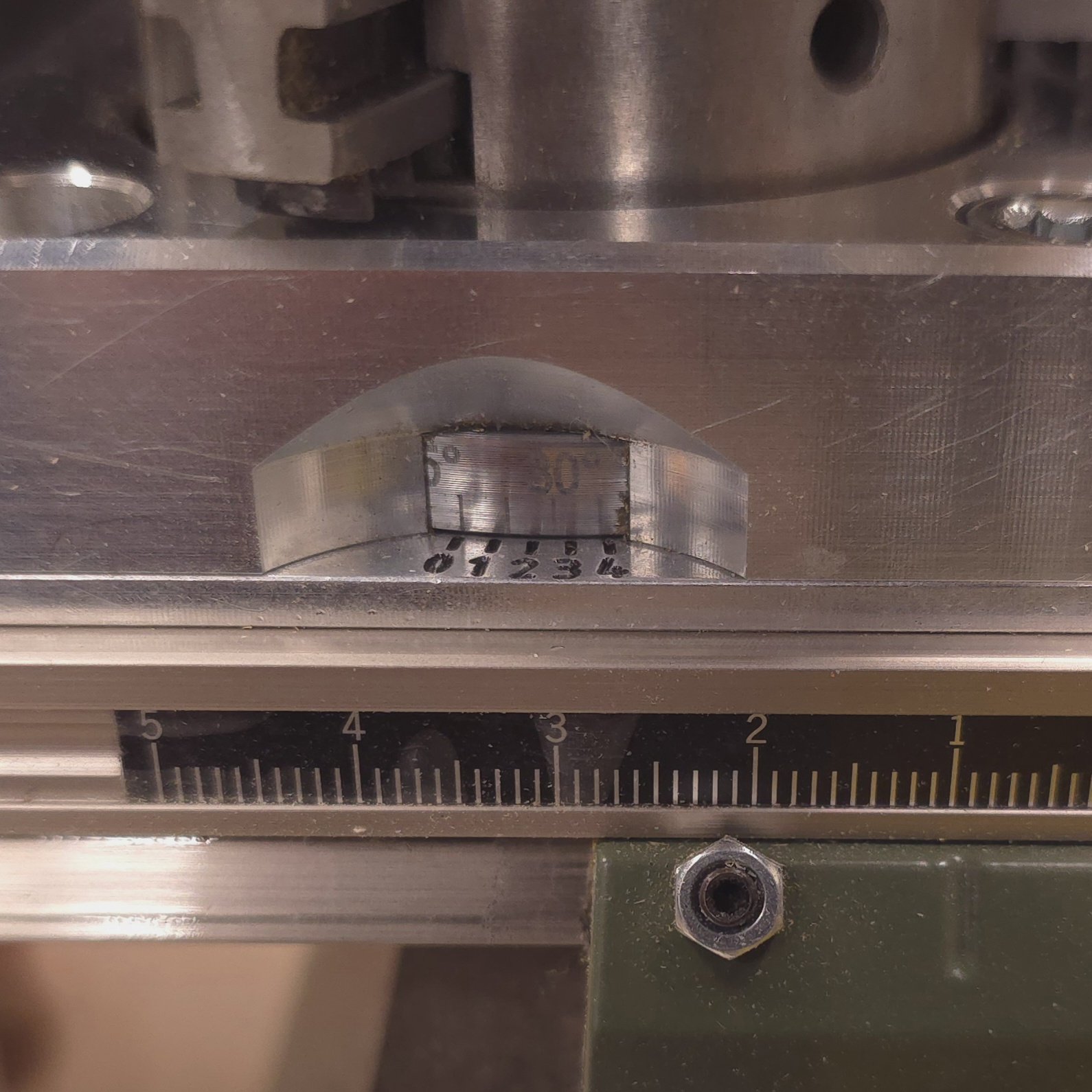
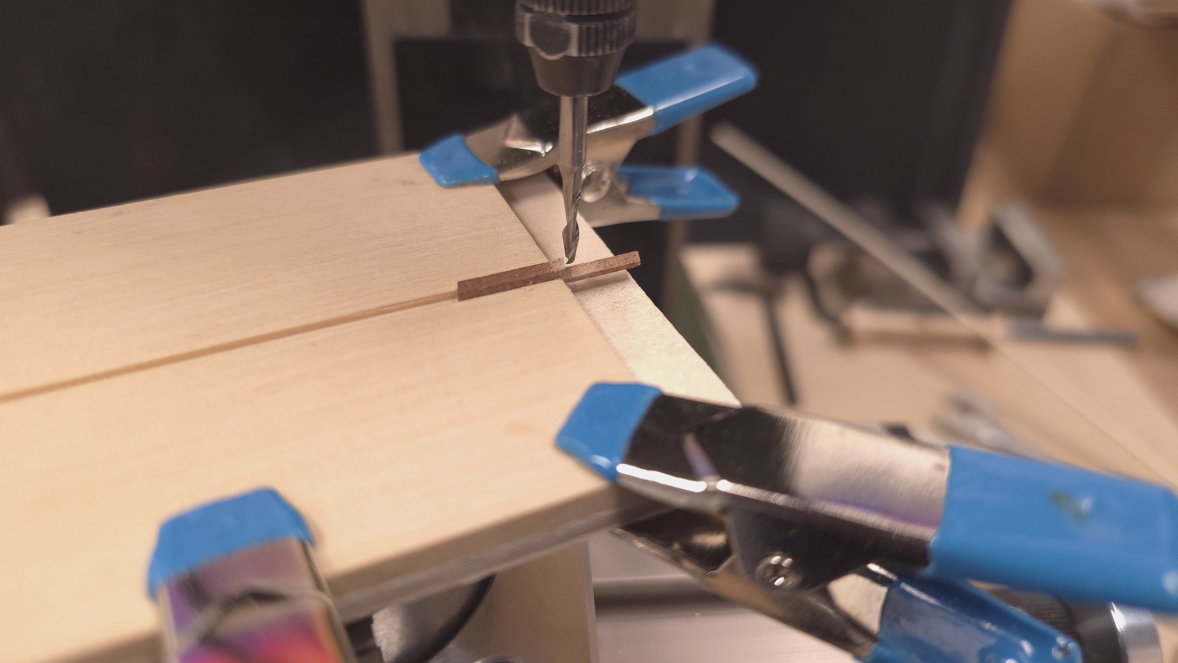
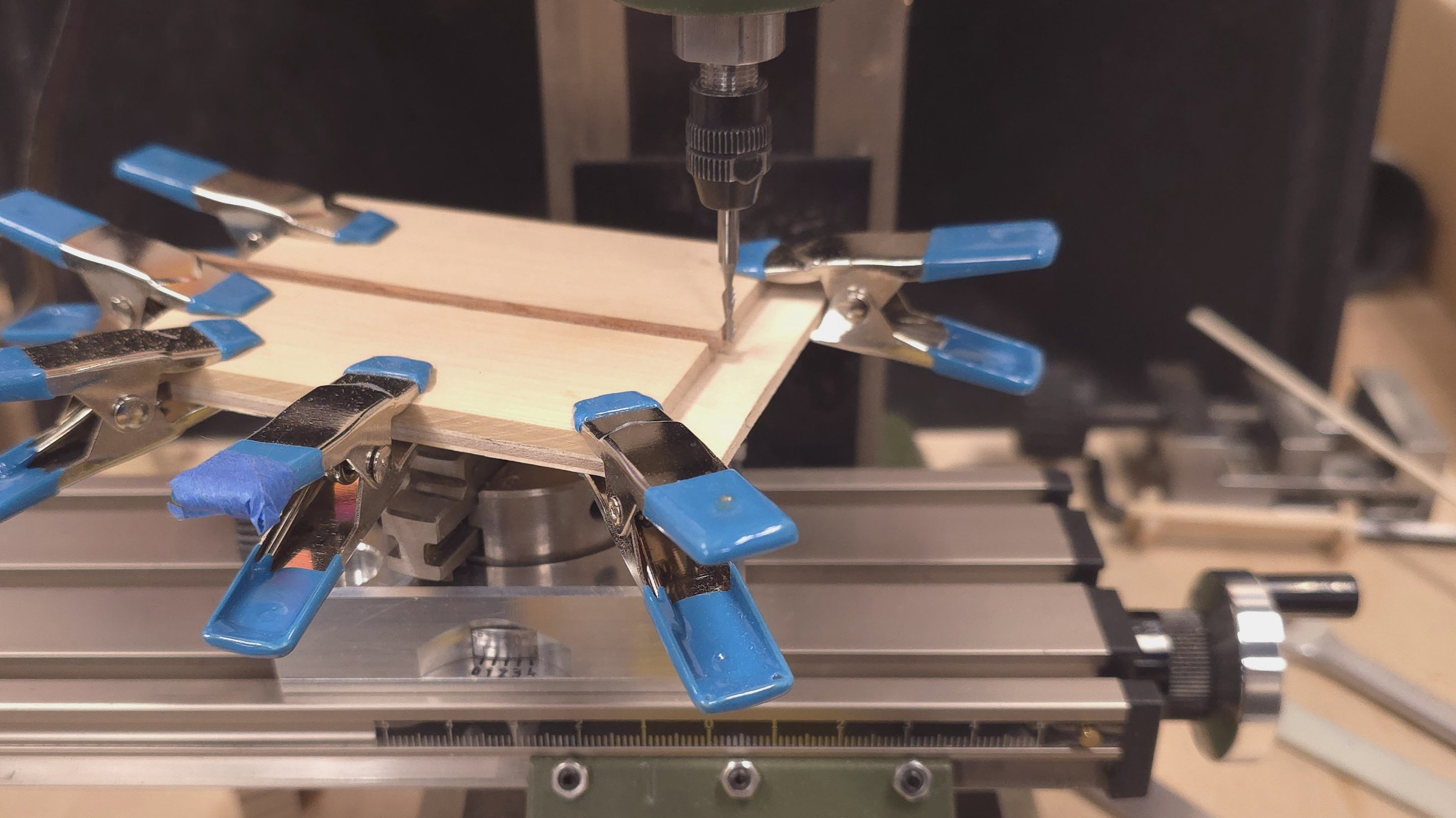
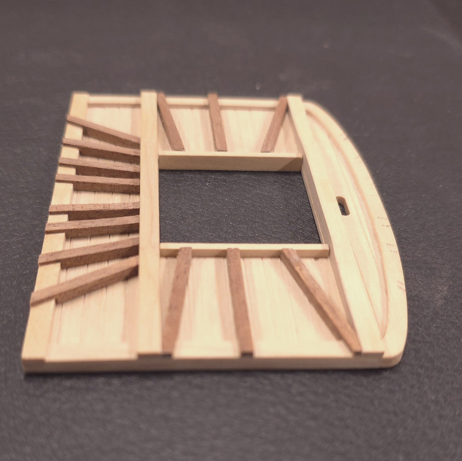
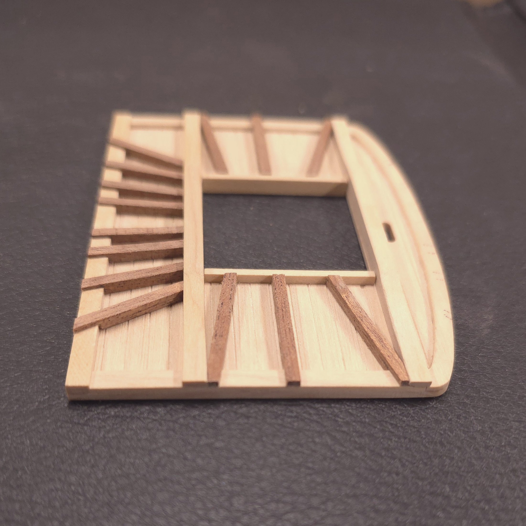
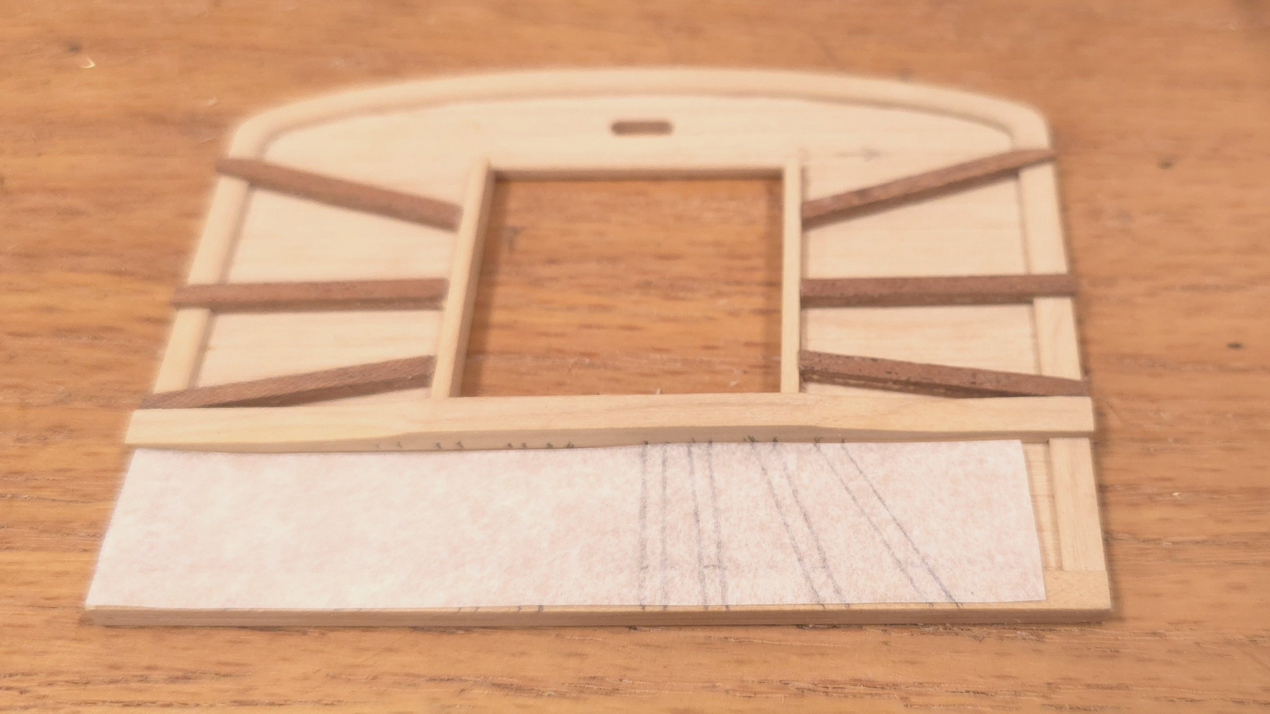
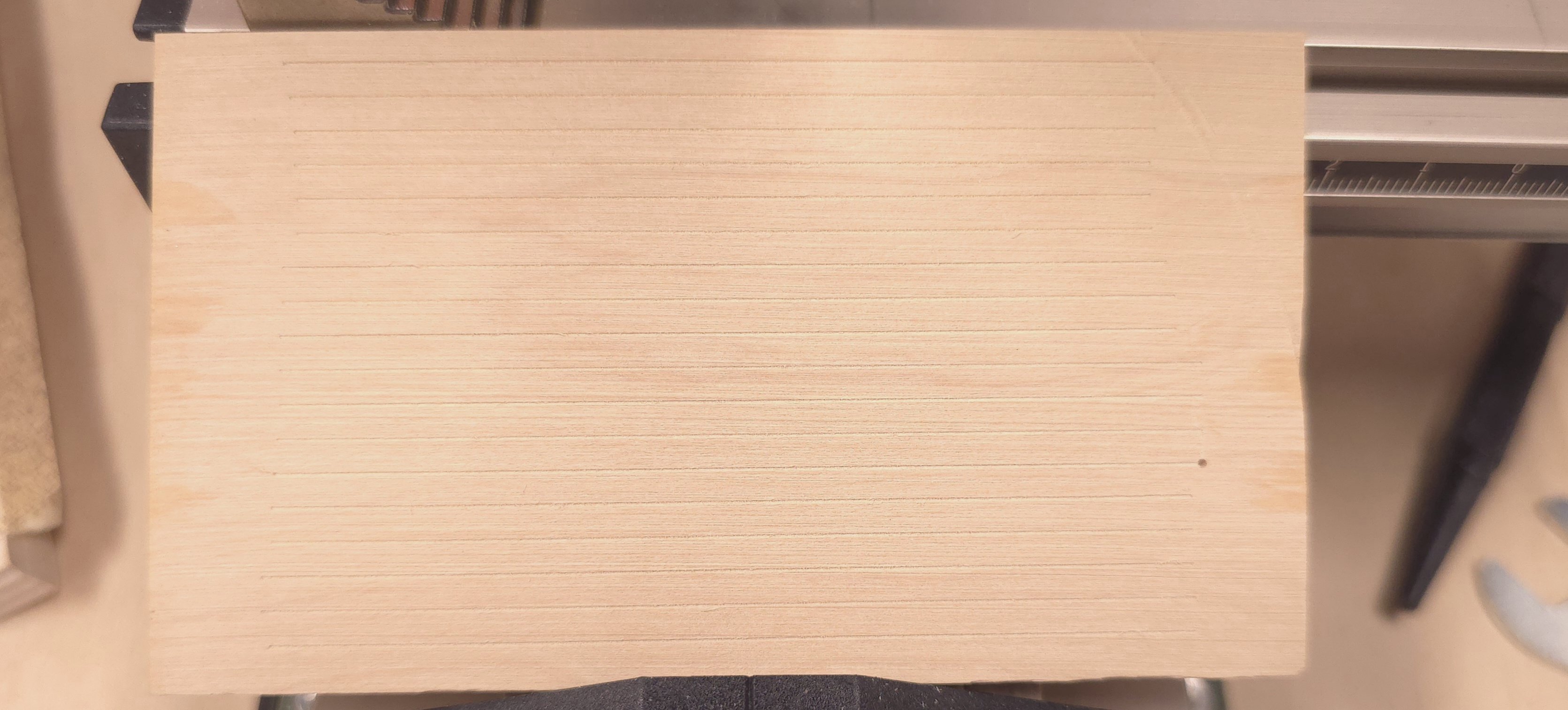
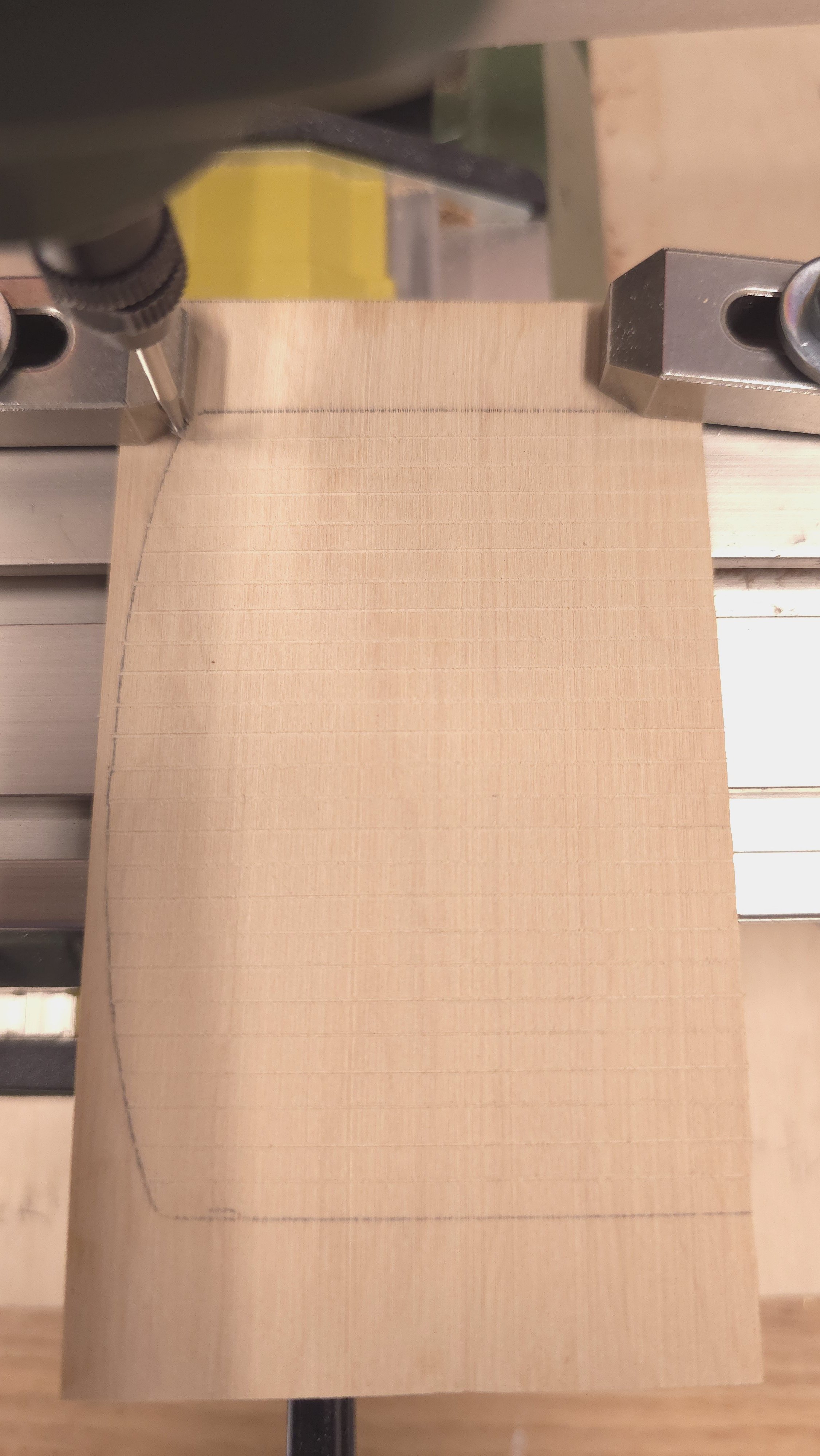
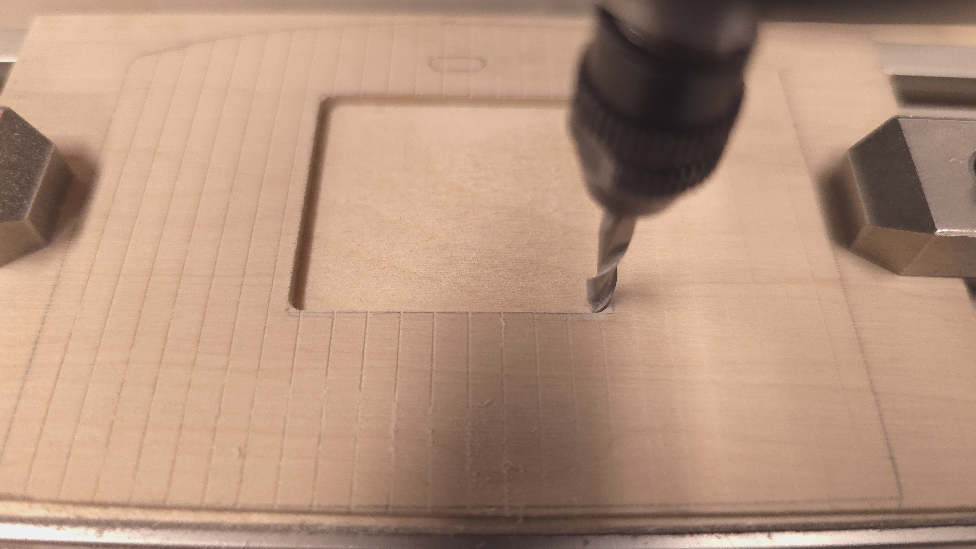
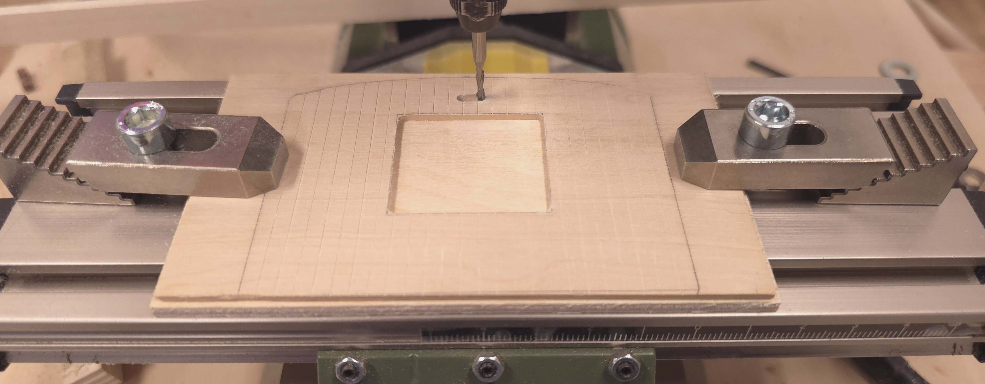
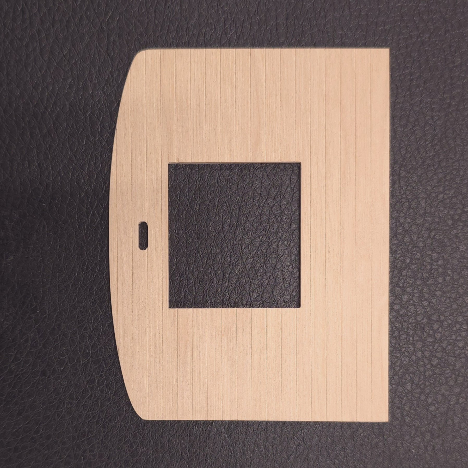
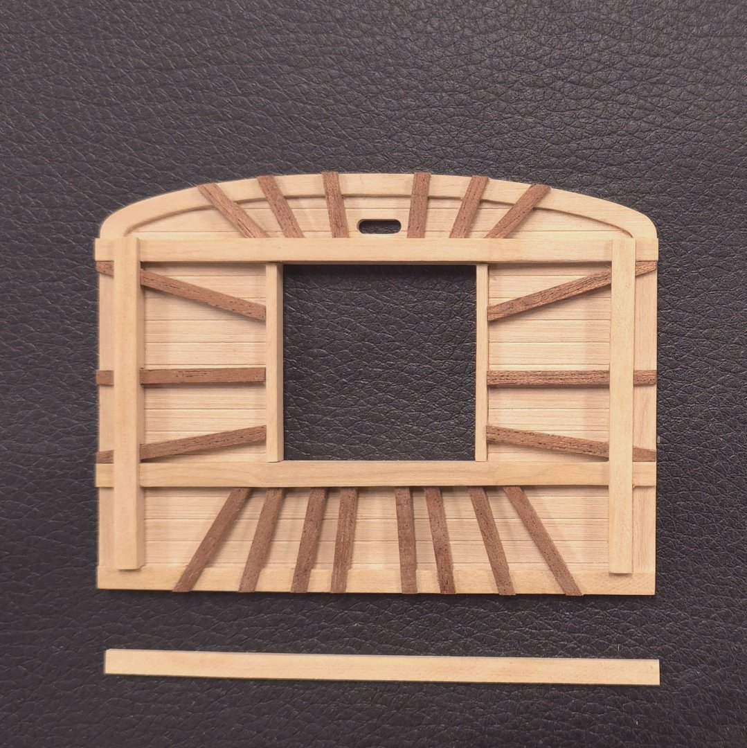
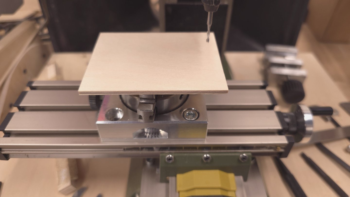
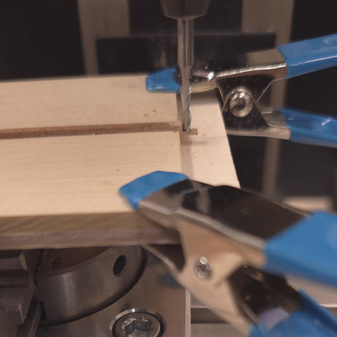
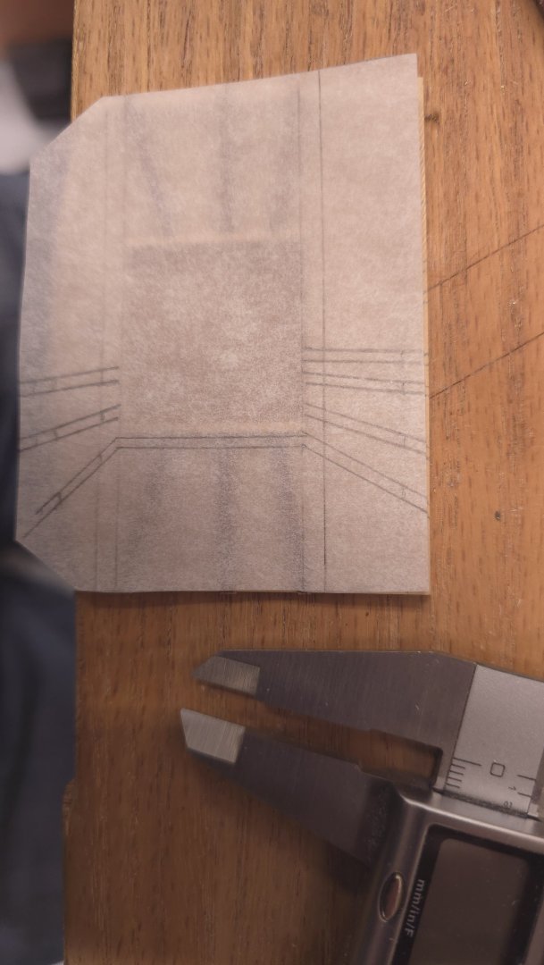
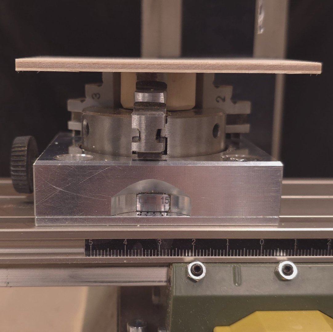
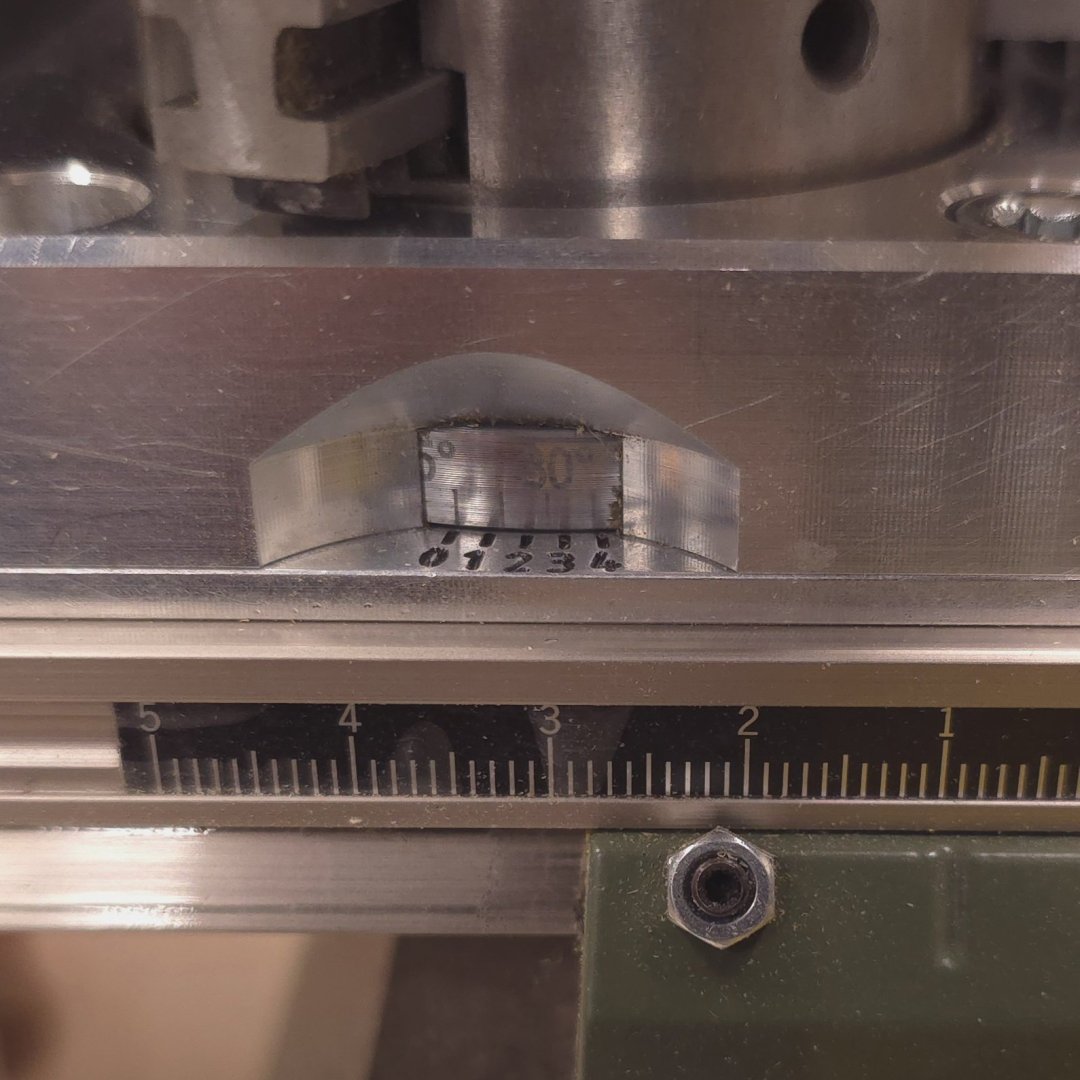
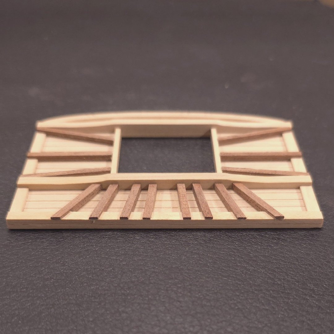
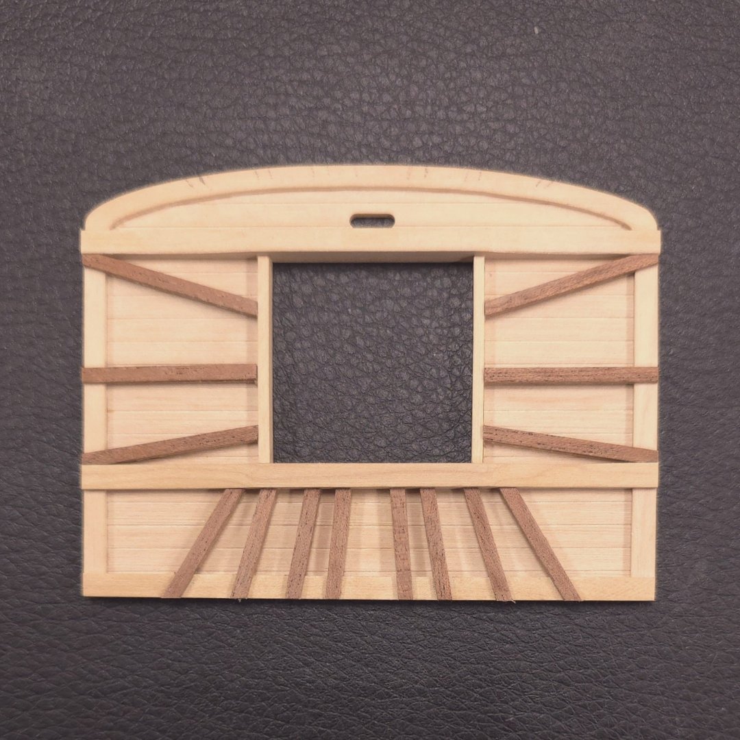
I just learned from reviewing Mustafa's build log, that he will be out of his Shipyard for 2 weeks. My hopes of catching up to him were dashed however, when I saw how long it took for me to deal with just the first of three fighting tops. (I've got close to 3 days into what you see below, and had really hoped to finish all of the battens on that today. Sadly, I just ran out of steam..) After looking at multiple build logs, several sets of plans, and then the beginning of my top above, I realized I needed to take a different direction. As you can see, my battens did not extend all the way to the end of the rim. The more I thought about it, the more I wanted them to go all the way to the rim. Furthermore, when I found out that the 1/64" sapele stock looks like it will bend pretty darn close to 90°, I decided that I was going to wrap that around the entire rim after everything else was built. So, here we go. Having angled the battens above on my belt sander, with a lot of trial and error, I decided I needed a better tool. Therefore, I constructed a rotating table for my Proxxon milling machine. I cut a short length of 1-in dowel, centered and glued it to a rectangular piece of Baltic birch plywood, then clamped the "table" into the Proxxon dividing attachment. The wood panel actually rests on the three Jaws of the dividing attachment. To hold the sapele strips, I clamped a rectangular piece of boxwood to the "tabletop" and milled a channel about half the depth of the 1/16" square stock I was using - and only as wide as would permit a fairly tight fit. I used my left hand as the "clamp" to keep the strip in place while working it with the mill. Using tracing paper, I copied the locations of the battens from the plans and transferred reference points to the fighting top. As an aside, the six battens you see immediately below, were all made with two pieces of 1/32" thick sapele. These were the ones I angled on the Belt Sander. I also made note of all the angles of the battens relative to the cross tree, and went to town making and installing battens. Drizzle drazzle drozzle drone, time for this one to go home...


-
I managed an hour or so at the shipyard today, not enough time to finish the sapele supports, but enough to get a taste of what it will look like.
-
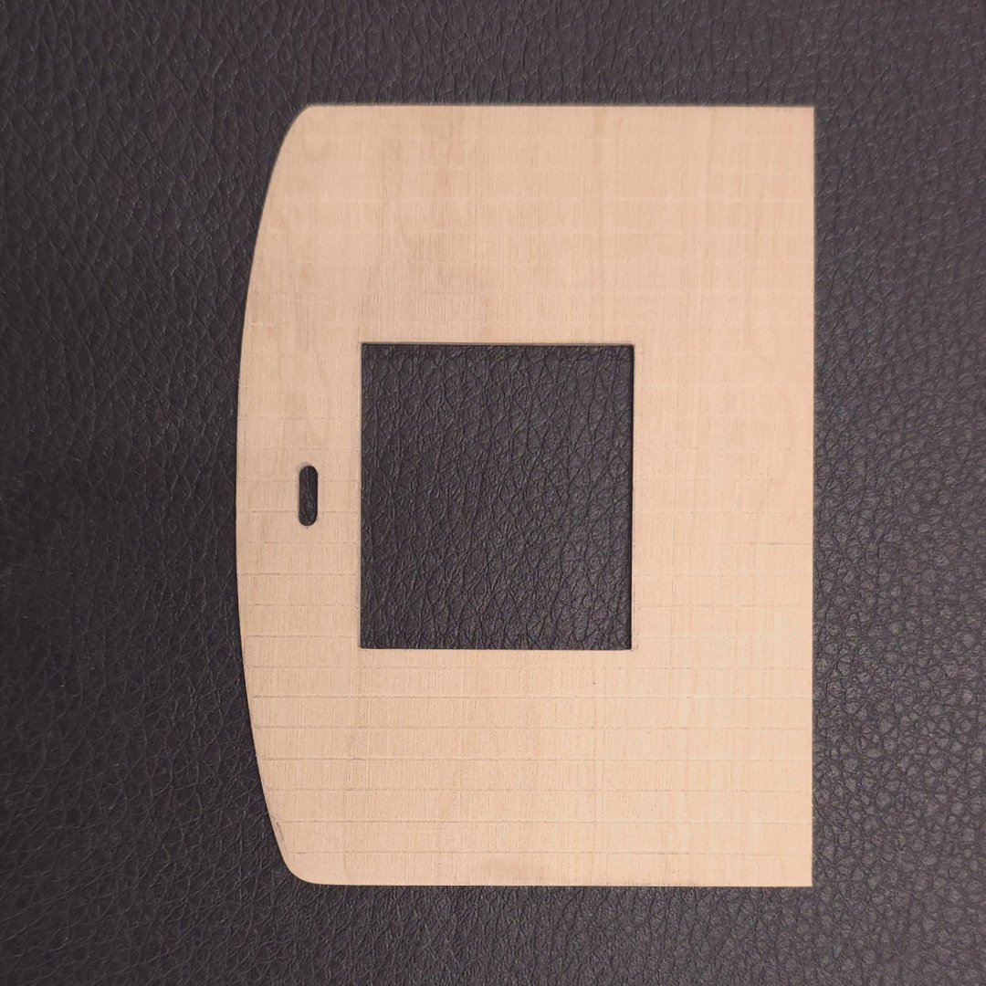
The grain running the wrong direction is a consequence of flipping the piece of boxwood I was working on over. I suppose I could have run the planking in the same direction on both sides, but the plans call for fore and aft orientation on the bottom and side to side on the top of the fighting top.
-
Butt joint what together? My original plan was to make 1/32" thick planks, which would have been butt jointed together and glued on the 1/32" kit supplied fighting top. This was an easier way of getting to the same end, and, as I said, no one (but Gregg😆) will notice the grain on the bottom side of the fighting top.
-
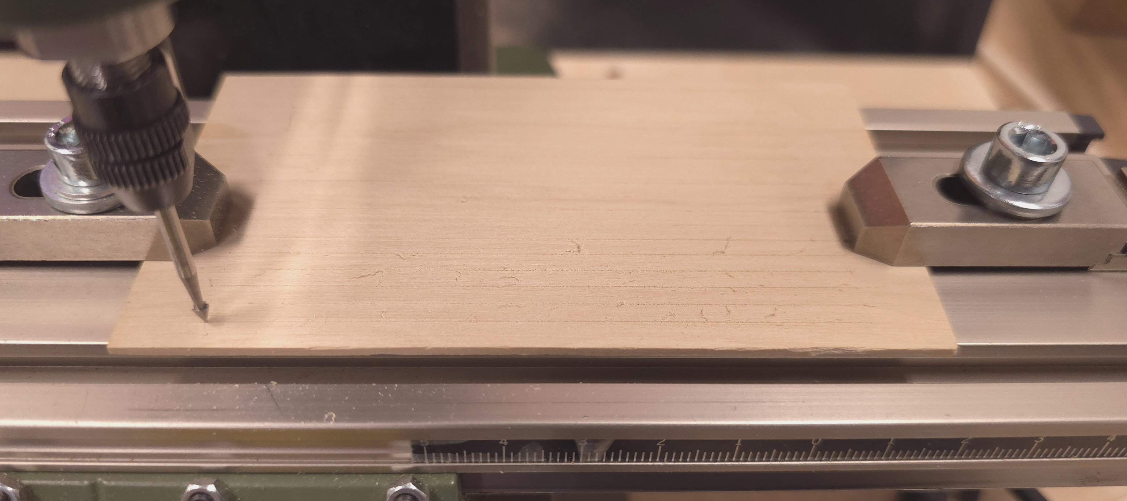
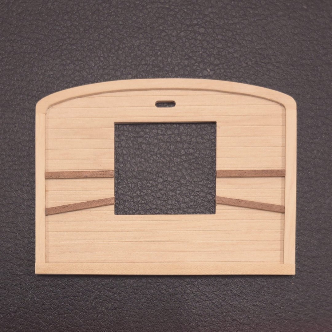
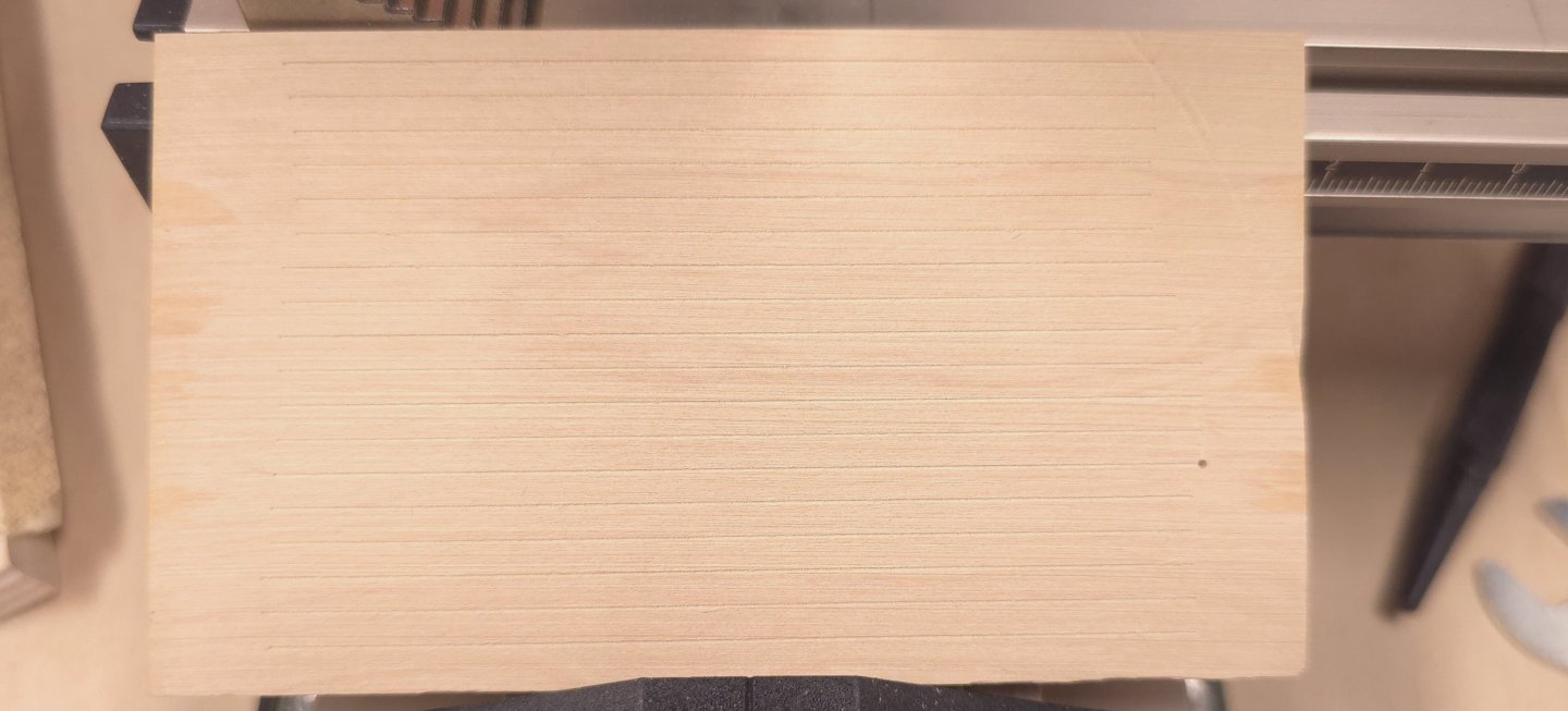
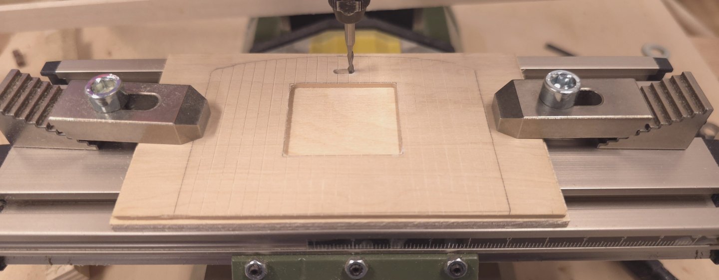
The more I thought about doing individual planking, the less I liked the idea for this application. So I resorted to a trick I used for the planking underneath the smokestack and on the three gun port lids at the transom. Using 1/6 inch thick boxwood, I used the pointy bit on the Proxxon mill simulate planking. The rest is self-explanatory. I can't say that I'm thrilled that the grain in the boxwood runs perpendicular to the fake planks on one side. Fortunately, this will be used for the bottom of the fighting tap, and no one should be looking up from the deck to see if the grain matches the planking. At least that's my hope. 😎🙏 My plan is to make a 1/32 inch thick rim out of boxwood for the sides and front, and to use 1/16" wide 1/32" thick sapele for the supports that radiate outward from the center. The back edge will be 1/8" wide and 1/16" thick boxwood. Finally, if I can get the 1/64" thick sapele to bend nicely, I'll wrap the outside edges in that. Yep, that's the plan. Let's see if theory become reality... 🤔 ( this is the look I'm shooting for.)


-
I'm not sure that helps. I think I'm waaaay over thinking this. 🤯 but, thanks.
-
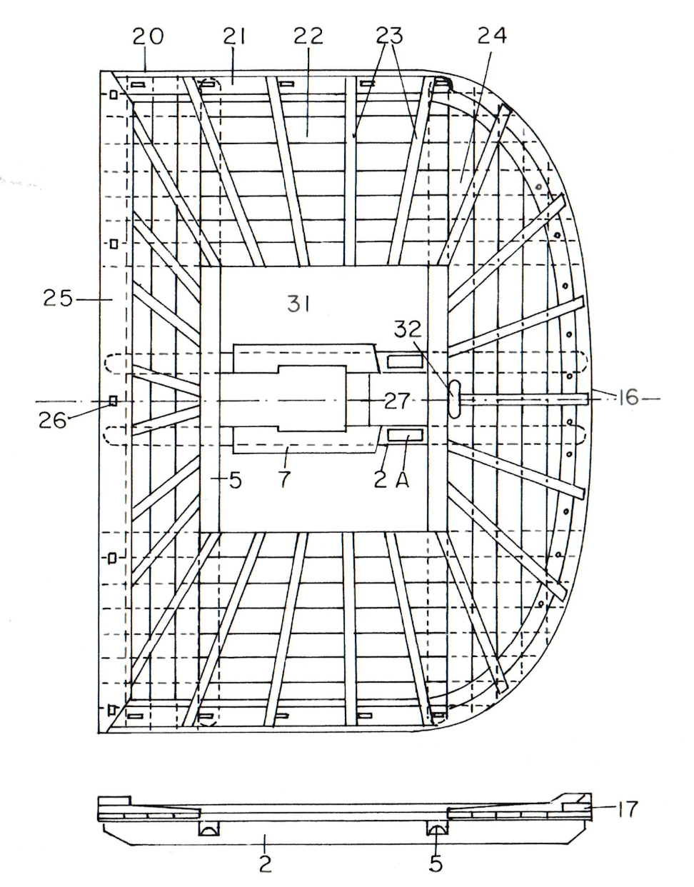
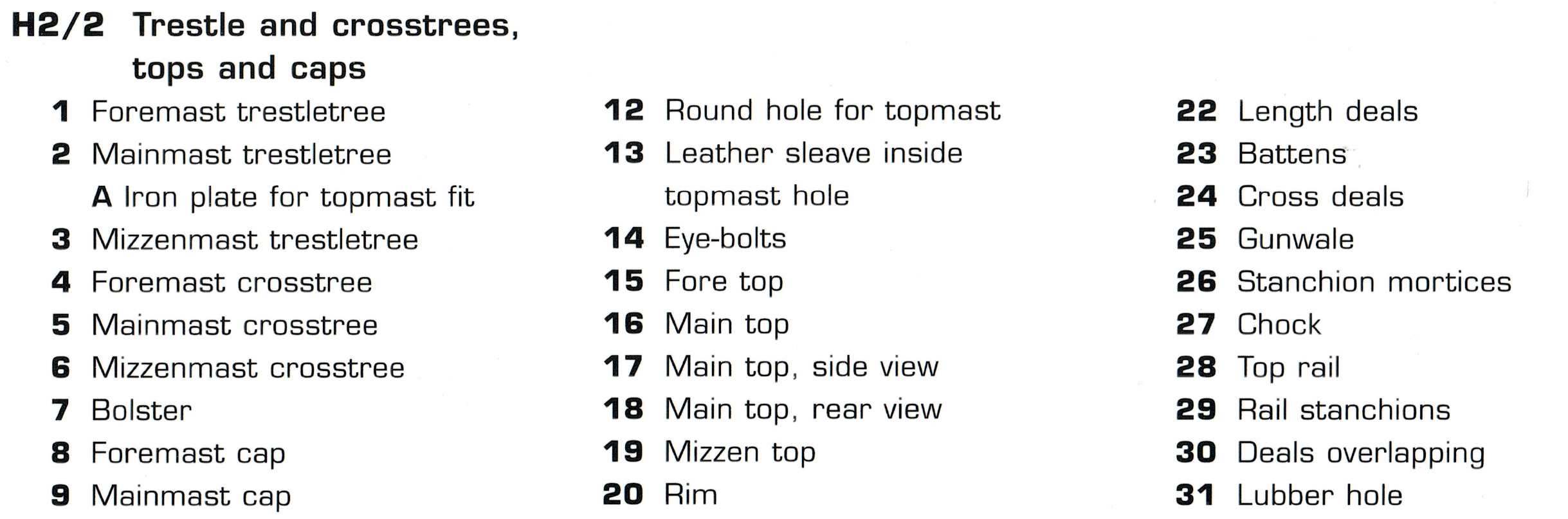
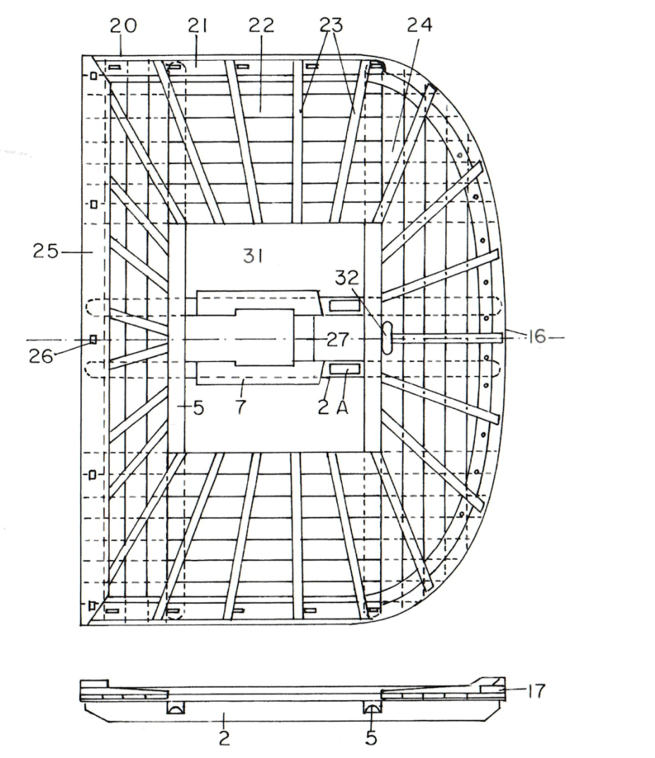
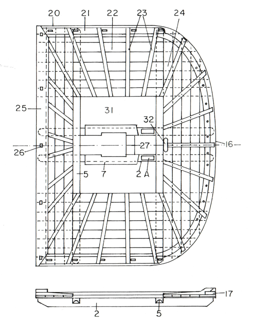
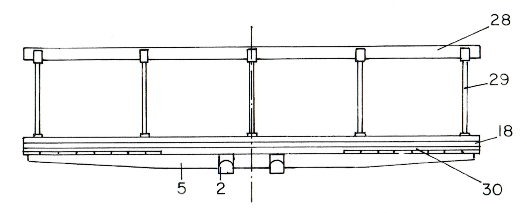
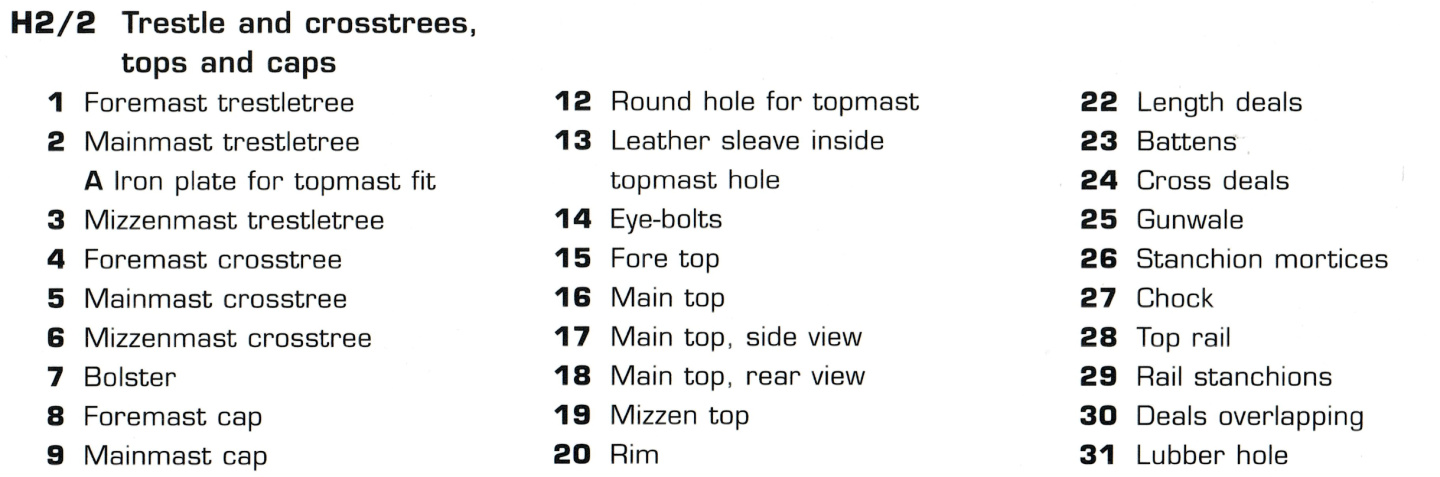
Interesting details on the planking for the fighting tops. They run broadside at the top vs fore and aft on the bottom - as shown in the photos in Jon's post to Mustafa's log below: Posted October 22, 2025 I can't speak for Mustafa's model but technically.. Jon Checking Marquardt, I've confirmed that the planking does run as mentioned above. Looking at this construction as a practical matter, I have to ask myself if it's even worthwhile to plank the fighting tops. To keep things to scale, the rim around the entire top should be 1/8" top to bottom. The rim seems to be flush with the planking on the bottom of the fighting top and proud of the planking at the top of the fighting top. The laser cut piece that came with the kit is 1/32" thick. The math therefore suggests that the planking needs also to be 1/32" thick. Three layers of 1/32" material adds up to 3/32" which would allow for the rim to be proud of the planking by 1/32". Because I'm not painting, material choices need to be considered. I thought about using the sapele that came with the Constructo kit for the planking, but the edges tend to disappear when joined edge to edge. I looked at HipExec's build log to see what colors the Constructo kit specified. They provide a material that falls midway between the color of the sapele and basswood. But I don't have that contrast anywhere else on Conny, so I should probably to consider binary choices. Basswood planks, sapele rims? Sapele planks, basswood rim? The battens would have to be the contrasting color as well. Decisions, decisions. (I don't think I'll be finishing Conny by July - the three year anniversary of the start of the build.) Here are parts of the scan of the Marquardt (Anatomy of the Ship) plans. What is not clear is, if there's a third layer between the planking? See item 30 - "deals overlap". I think it's now merely academic, since I've already spent way too much time researching this. I'll attempt the three layer with rim plan above.
-
Yeah, sorry about that.. I'm still trying to wrap my head around the details of the fighting tops - specifically the dimensions of the three layers comprising the 1/32" part supplied with the kit, the fore and aft planking on the bottom, and the side to side planking on the top. I won't bore you with details here. When I do figure things out, my build log will show the results of the research. Thanks for chiming in.
-
Tom, I hope you’ll pardon my trip to your shipyard via Way-Back Machine, but since I’m starting work on the fighting tops, I’m looking at build logs to help fill in the gaps in my plans and experience. The plans (page 6) show that the top platforms are 1/32” thick. And a note below the drawings of the three tops says, “This (sic) is fore and aft planking on real ship.” You said above, if I’m not misreading, that you planked the top and bottom of the platform, with 1/32” stock. Furthermore, you said you used 1/16” wood for the edge and side pieces. My math suggests that the thickness of the tops add up to 3/32”, which is thicker than the side and edge pieces. Did you only plank the top’s tops? Bottoms? Did you use wider material for the sides and edges? Or did you sand a 64th off of the top and bottom of the fightings top after planking? (and Jon, if you’re following along, I KNOW you recently supplied me with the official plans showing the planking, but for the life of me, I can’t find that post. Please steer me in the right direction. Thanks) Best, Peter
- 1,354 replies
-
- 1
-

-
- constitution
- model shipways
- (and 1 more)
-
Two down. That's the lot. (my apologies to those who have already seen and reacted to this post, but before I added this last photo.)