
Der Alte Rentner
-
Posts
1,025 -
Joined
-
Last visited
Content Type
Profiles
Forums
Gallery
Events
Everything posted by Der Alte Rentner
-
 I just did. Thanks for the suggestion.
 -
I already have some sheet stock ordered from him in thicknesses of 1/16", 1/32", 3/32 and 1/4" in boxwood. I suppose I can rip some strips from that and hope it bends as severely as needed for the stripes. XKen made it sound like basswood would take a better bend, and another contributor at his build log suggested that holly was the best. Modeler's Sawmill doesn't provide either. Hence my search for another supplier. I really would like to see how holly flexes. I do have some Ace Hardware 1/32" basswood. I guess I'll put on my sawmiller's hat tomorrow and start ripping my own strip. If you're going to paint the hull black, I think you'll enjoy working with styrene. I don't know how seriously I'd worry about it discoloring over time, as other contributors have reported elsewhere at MSW. But it was an easy material to work with for the gallery windows. Thanks Gregg.
-
Can anyone recommend a supplier for #8000 (.0208 x .0208 x 11") basswood, boxwood or holly strips? Xken used this material to do his bow stripes. I don't wan't to use styrene because I'm trying to stick with the stained/unstained contrast scheme. I've tried an internet search and struck out - the few sites that showed it were out of stock. I suppose I could try making my own, but if someone knows someone.. 😉
-
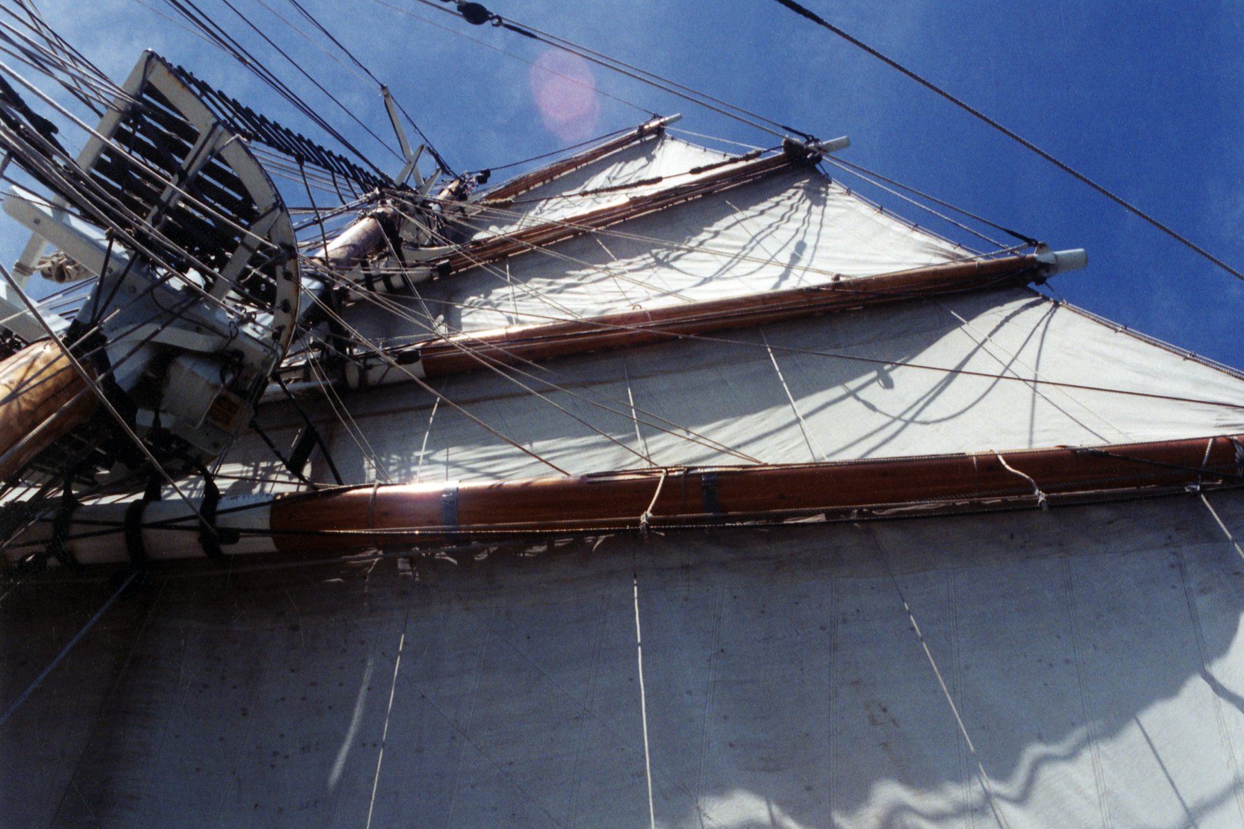
Jon, I can't thank you enough for having provided this photo to XKen, way back in 2016. It answers a big question for me on how to tackle the tailboards. Thanks again. Peter
-
Funny you should say that. You should look at the discussion on cannons at Musafa's (mtbediz) build. You'll need to buy replacements for the half barrels that came with the kit. Furthermore, you probably won't like the carronades that came with the kit either. At present the Syren Ship Model Company's (https://syrenshipmodelcompany.com/) cannon store is closed. But I'm pretty sure that by the time you're ready to build the gun carriages, the site will be back in business. Or you could see if Mustafa's friend will make some for you..😁 Do you have a lathe?
- 233 replies
-
- 2
-

-
- Model Shipways
- constitution
- (and 5 more)
-
USS Constitution by mtbediz - 1:76
Der Alte Rentner replied to mtbediz's topic in - Build logs for subjects built 1751 - 1800
I'll chime in for the dark grey as well. Looking good! -
USS Constitution by mtbediz - 1:76
Der Alte Rentner replied to mtbediz's topic in - Build logs for subjects built 1751 - 1800
Geez, Jon, you just beat me to the punch. I went back to my build log, where you posted the photos of Conny's carronades. By the time I got back, here you are - being all reasonable and coming up with good ideas. I'll copy your photo here so Mustafa can compare his work to the present day guns and decide between weathered or like new. (My guess? He's going to try for the uniform finish. In which case, you're prescription should indeed provide the cure.) -
Likewise trying to recall, without making a fool of myself 😉.. I think the carronades that came with the M.S. kit measured around 25mm in length. Looking at the HisModel offering above, I'm pretty sure their carronades are going to be about the same size as the slightly shorter Constructo provided guns. I'll revise this post when next in the shipyard.. (can't do it until I fix the garage door cable, which I discovered yesterday was severely frayed. I'm not risking my truck in the hope the cable won't snap as I'm driving it out of the garage..)
-
As always, Jon, thanks for the images. My reference library grows, but it will never compare to yours.
-
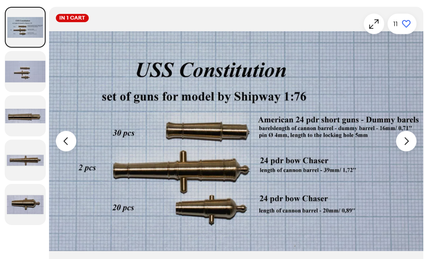
Thanks for all the feedback guys. I took a look at the Model Monkey product, and while the price wasn't half bad (if I read correctly, 8 ea. for $18 and change?), I didn't like the look. Preferring brass, and wanting to avoid filing the Model Shipways dummy barrels to fit the holes in the gunports, I took a chance on this more esthetically pleasing offering from HiSModel (available through E-Bay) instead: This is the link: https://www.ebay.com/itm/225798488561?_trkparms=amclksrc%3DITM%26aid%3D1110006%26algo%3DHOMESPLICE.SIM%26ao%3D1%26asc%3D20231107084023%26meid%3D99995fd3ece648bbb639713d73e121c0%26pid%3D101875%26rk%3D4%26rkt%3D4%26sd%3D224832281882%26itm%3D225798488561%26pmt%3D1%26noa%3D0%26pg%3D2332490%26algv%3DSimVIDwebV3WithCPCExpansionEmbeddingSearchQueryRecallAuctionPushout%26brand%3DModel%2BShipways&_trksid=p2332490.c101875.m1851&itmprp=cksum%3A22579848856199995fd3ece648bbb639713d73e121c0|enc%3AAQAJAAABMM%2BSIK5LCqs2uiCwInhHqGVzIMLIMo0iPltG%2Fc%2FV8dzqXG8bAAbTVw985HbdYTuG2wPTDx%2F8lbe8GSu4NUrsEPcDBvCLFhf2QkBmtTX5yUHKQb00aHrCAEqnL1H7RiLKPWzAq77QSHjvkbp%2FD6QIw2d0cwYkcaEx1Le5vSJVNSpietrpaDU6XL1sU59PSFVgME0FeDqPYwDuID3a3%2Bvh%2F53vbte%2BQu3o0w6ieGjGnLdw3ubBmNku7FqvGzXRs3I0v8TOWfoozbZ0xH%2FPhofdDYM3ofsUrcQv82u8IpmkqnqOnqjo9lX%2Fga%2FLeb4CWX5A%2BXyq6RFdxkASoQYLBYDYK8XQg5x%2BvAMCkFig8VKslfNN0ARTWvpDjXV%2Bs8WBFrNZPfHCBzABYPTB8%2F1qV0GsQeE%3D|ampid%3APL_CLK|clp%3A2332490&itmmeta=01JGY06WJ0VRGHK6MCB5SMVHY0 Given that I'm building the model to my own taste and (in)experience 😁, I'm not all that concerned about historical accuracy (or scale). I'm hunting around the shipyard for some ebony left over from a previous project in the hope that I can build the spar deck gun carriages from that - because I think that would net some really awesome results. If the ebony doesn't turn up, I could paint the assemblies made from the M.S. laser cut stock, or simply use the Contsructo kit carriages. The latter look pretty good. The HiSModel carronades look to be longer than those in the Constructo kit, but since the carriages appear to be the same size. I'll likely be mixing and matching. At any rate. Construction of the carronades will be relegated to the upcoming Floridian hiatus. I'm hoping the HiSModel dummy barrels fit the gunport holes without modification.. In the short term I'm still on the sidelines awaiting a shipment of boxwood sheets in various thicknesses. Lastly, I was hoping I could find the cannons at Syren Ship Model Company. Sadly, that part of their store was "closed for maintenance"

-
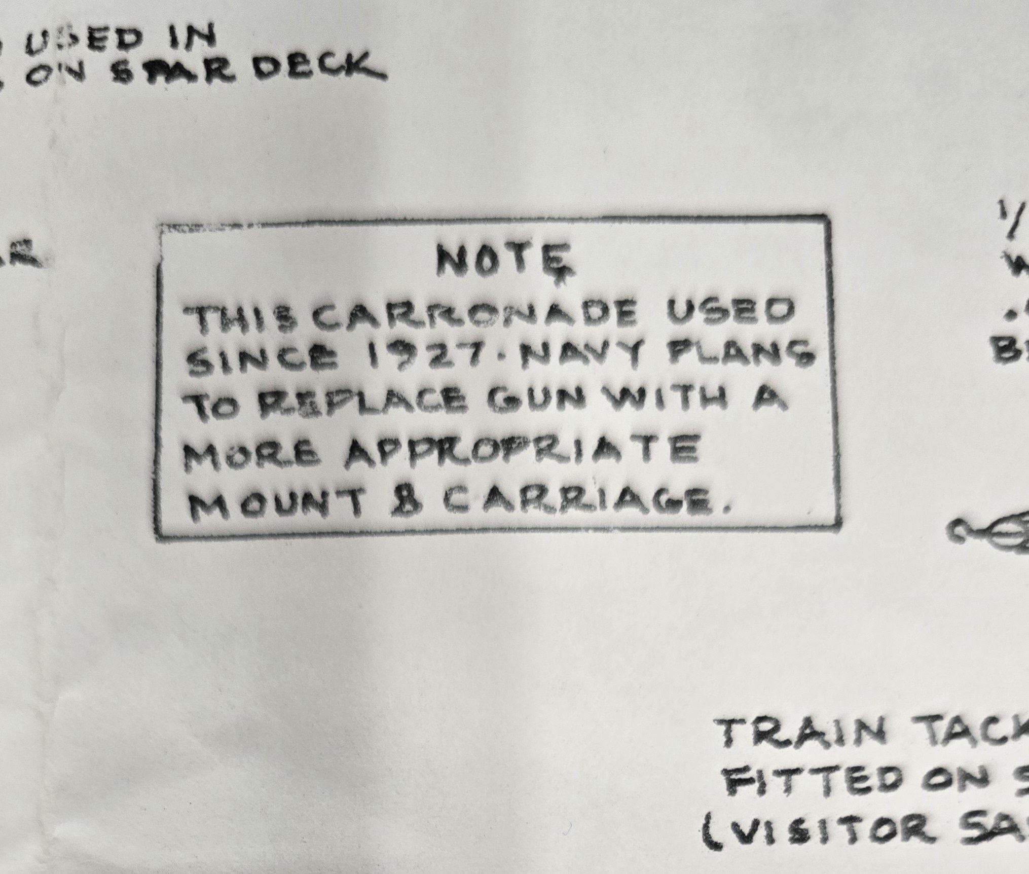
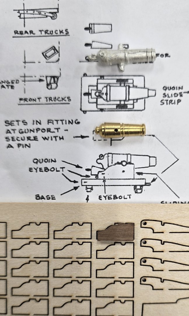
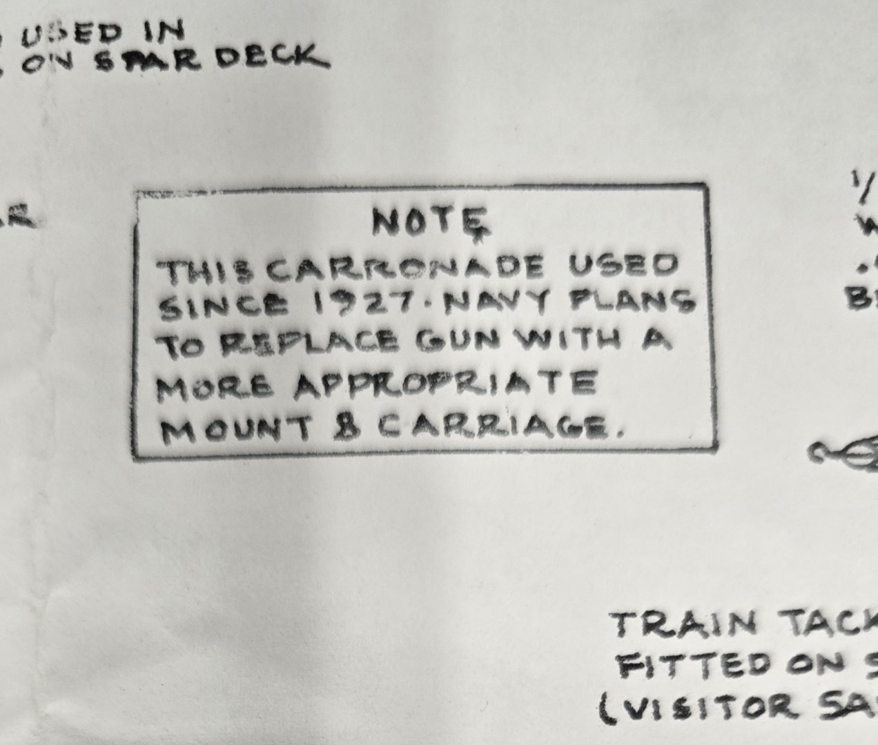
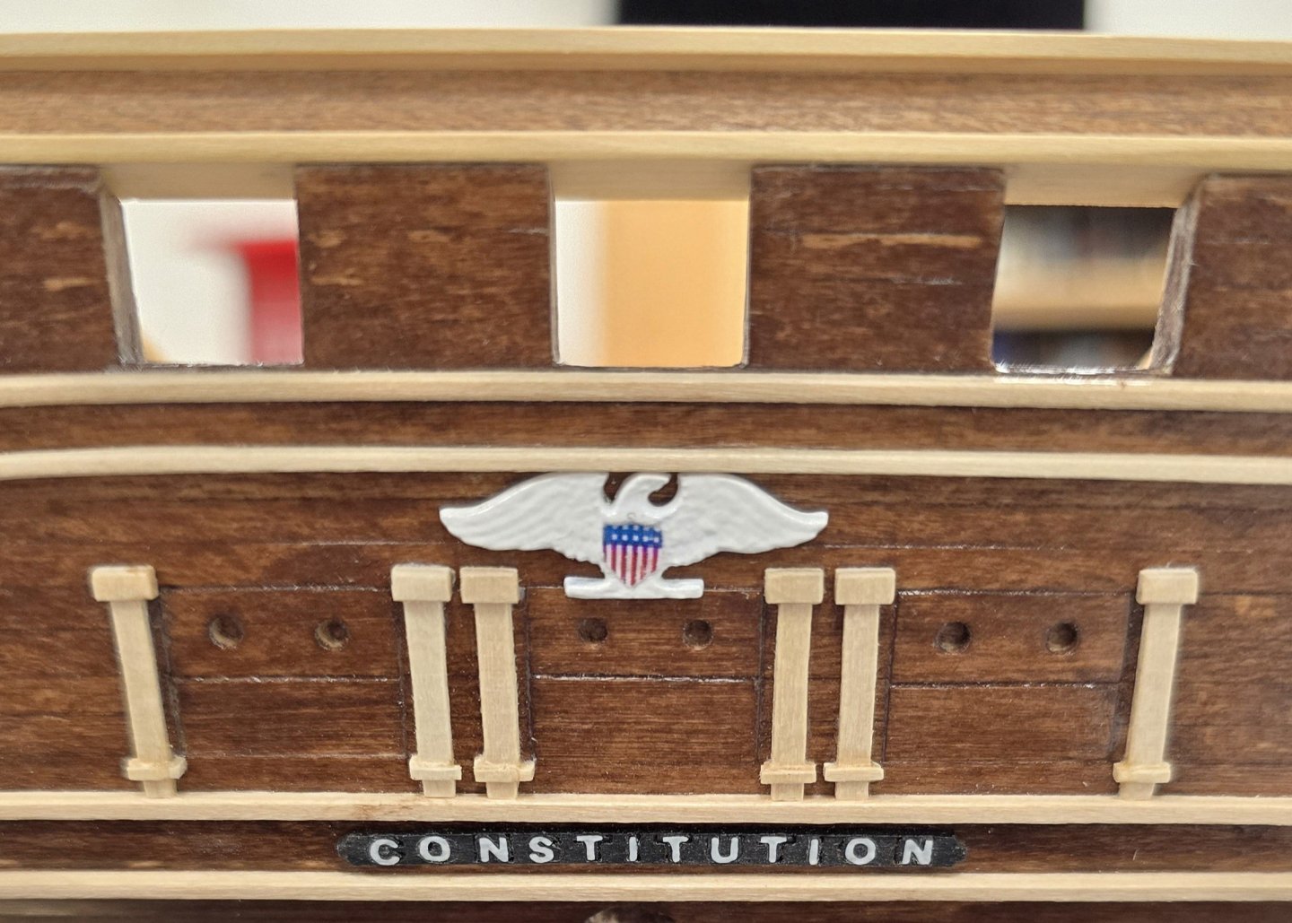
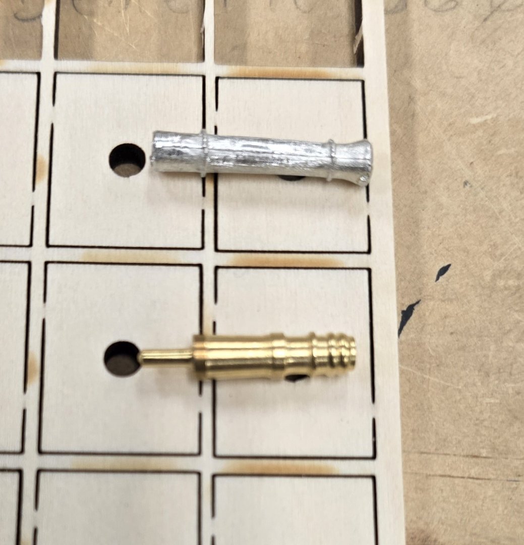
It has been a very busy holiday season, and I am just now returning my attention to the shipyard. As I await a delivery of boxwood, so that I can complete the main and top gallant rails, I'm beginning to plan my upcoming trip to Florida. What can I do to occupy myself with the USS Constitution in a hotel room? How about tackling the half barrel cannons, the carronades and their carriages? The castings that came with the kit are abysmal. But if I bring the parts along, with some files and sanding sticks, I might be able to clean up the carronades and cannons, and make the latter fit the holes in the gunports. That's a lot of busy work, which will certainly occupy my idle time in Florida. However, I compared the parts between the Model Shipways kit and the Constructo kit, and I'm wondering if I can at least swap out the carronades with those from the Constructo kit. The carriage sides seem to be identical in size. The guns themselves are shorter, but they look a heck of a lot nicer than the crud from M.S. Model Shipway carronade vs Constructo (Constructo supplies brass and sapellly wood) Also, what should I make of this note? Filing the half cannon ends to fit the gunport holes might be unavoidable, as the Constructo parts won't fit. One small accomplishment - thank you Clement for printing me the Eagle!
-
Hmm, forcing yourself into a "kit bash" just because you wanted to go for open gun port lids. That was an interesting decision. I might have given more weight to "or rather had fully removable lids instead of the split lids provided in the kit", and opted to install closed lids, skipping the gun deck guns all together. Nice workmanship and attention to detail so far.
-
Als wir hier sagen, Happy wife, happy life, Alles Gute
-
I hear you loud and clear, Jon, and will cross that bridge (swearing all the way) when I finally get there. Though, it may take a while, given my tendency to overthink things - and for my boxwood vendor to deliver fresh supplies.. Thanks again and Happy New Year
-
Perhaps it's because of the nature of a super zoomed photograph, but I'm not entirely convinced on the color. But then, when I saw the spec of 1/16" square on those styrene junction boxes, I had to gulp. Yikes! This is a long way off for me, and I may not bother with them anyway, but, I think I would try to find some 1/16" square brass stock and drill holes in that instead of messing with styrene. Or hunt down someone who has plans for the canopy frames and can knock them off with a 3D printer (in this country). I have a friend who has a 3D printer, but he'd need plans or whatever the specs are called for him to make them for me. I'm beginning to wish I'd started with a much larger scale, so that I wouldn't need an electron microscope and nano robotics to work on these smaller details. Nice work Jon.
-
You carved the scrollwork out with a razor blade? How is that possible? Working on those pillars on the transom with super sharp Xacto blades caused all kinds of splitting. How did you avoid that on this laser cut piece? There MUST be more to this story.. Nice work on the headrails! I haven't seen anyone else do it quite the way you did it - actually installing the timbers first.. Even the Hunt practicum put the cart before the horse in this case.
-
IMHO, an excellent choice..
-
Going back and forth between builds, trying to firmly grasp construction details of cheek knees, trailboard, and head rails, I was impressed by your work in this area. I will go so far as to say that IMHO you eclipsed XKen in managing the curve at the tail end of the trailboard, where he cut it short. Boy of boy, am I dreading this step..
-
Jon, I spent some time today checking other build logs, one of which was XKen's. I noticed that the drills he uses seem to be very short, or have very little of the cutting end protruding from chucks. This might be a technique that would resist your drill bits breaking. He doesn't discuss it, but I suspect he shortened the cutting end of the drill bits and hand sharpened them. E.G. That last one might have been an outlier..
-
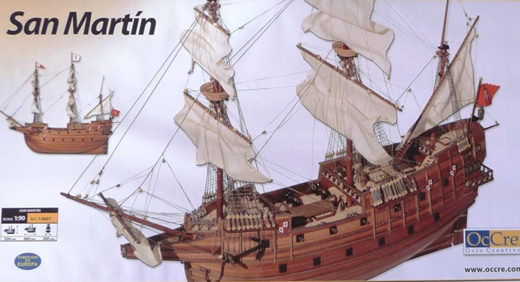
My vote is for top left. This seems to most closely match (to my eye at least) the color of the sails on the photo on the model's box cover. No?
- 210 replies
-
- 1
-
-
- San Martin
- OcCre
- (and 1 more)
-
USS Constitution by mtbediz - 1:76
Der Alte Rentner replied to mtbediz's topic in - Build logs for subjects built 1751 - 1800
I hadn't planned on using the router bit on the MF70. I would use my router table, like I did to make the hatch coamings (post 203) and the base (post 184). I see that you've already concluded your mass production run and that you are well on the way to completing the gun carriages, so I will not pursue the topic further at this point. Instead, I've got to see how others are handling construction of cheek knees, head rails and trail boards. I thought I dreaded the galleries, but those efforts pale in comparison to what I foresee coming up next. I look forward to seeing you you tackle those last items.. Right now, I'm looking at Usedtosail, Kmart and XKen, among others for ideas and techniques. -
I'm finishing up the main rail and starting to think about the top rail, but dreading tackling the trail and head rail construction. I'm studying your bill very carefully and thank you for providing such detailed photographs. The hardest problem I've had is visualizing what these would be like. Your pictures have really helped.
-
USS Constitution by mtbediz - 1:76
Der Alte Rentner replied to mtbediz's topic in - Build logs for subjects built 1751 - 1800
I'm still of the opinion that a router bit would be the best option here. Next time I'm at the shipyard, I'll run through my collection of bits and see if I can find anything that would facilitate the shape that you're looking for, Mustafa. If I succeed I'll show you some photos. I hadn't intended to make my own gun carriages, but if they look better than what came laser cut from the kit, this will have been an instructive conversation. -
USS Constitution by mtbediz - 1:76
Der Alte Rentner replied to mtbediz's topic in - Build logs for subjects built 1751 - 1800
I wish I had a friend like that!