
Supplies of the Ship Modeler's Handbook are running out. Get your copy NOW before they are gone! Click on photo to order.
×


Decoyman
-
Posts
97 -
Joined
-
Last visited
Reputation Activity
-

 Decoyman got a reaction from fatih79 in Chaloupe Armee en Guerre by Decoyman - from the Delacroix plans
As you may have noticed I have not made any posts for a while. Pressure of work and now a new job have all made work on my chaloupe nigh on impossible, sadly. I do have some progress which I have not yet reported on and in which you might be interested.
Since my last post I have faired the frames as far as possible. Here are a couple of photos:
However at this stage I began to think something was wrong.... It took me a while, but after much fiddling trying to get the keel, stem and stern posts aligned to each other and square to the mould, I realised that the mould itself was not true. This photo shows the problem:
I think that the stack of MDF laminates was able to slide sideways at the point while the glue was still wet and I was tightening the clamps. I considered sanding the sides square, but concluded that this would only lead to a misshapen mould. So I made a new one, taking more care this time to ensure everything was aligned properly.
Here are the two moulds side-by-side. The differences are not obvious, but the second one is unquestionably more accurate.
Because I had not glued anything to anything else at this stage (with the exception of the floors and futtocks making up each individual frame) I was able to unpin everything from the old mould and re-fix it to the new one. Although the frames had been made over the old mould they fit the new one well enough, so in the end there was not much other than the mould to redo.
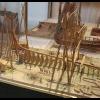
So now I was able to make proper forward progress with the transom. You can see the top piece in the picture with all the frames above. This pinned nicely to the back of the sternpost and square to the mould. The next step was to fix two pieces of thin (1.5 mm) ply, roughly profiled to the shape of half the transom, to each side of the stern post, tucked under the top piece. These were pinned in place until the glue was dry. The outer profile was sanded using a round sanding stick running across the last few frames. The outer surface of each side of the transom was boarded with 5 x 1 mm cherry and again the ends were sanded to the correct profile.
The final pieces of progress are the two wales. These needed spiling to the correct longitudinal shape and then profiling in section using a scraper filed into a piece of scrap brass. Once they were soaked and curved to the right plan form they could be glued in place. At this point the framework is strong enough to remove from the mould as you can see.
And that is nearly as far as I have got to date. I have made the two garboard strakes, but they are not finished yet or fitted. Hopefully I will get some more time soon!
Thanks for reading.
Rob
-
Decoyman got a reaction from fatih79 in Chaloupe Armee en Guerre by Decoyman - from the Delacroix plans
Thank you all again for your kind comments and likes. You made me feel inspired enough to find time to do a bit more!
I have made and fitted the first strake of planking either side of the keel. This is the first time I have attempted spiling of planking. So far it's OK... I have had to remake one strake through impatience, and the fit of each is not quite as perfect as I would like. The following photos show the garboard strakes being glued in place. I will post some more once I have several done.
The last photo shows the stern. You can see the ends of both strakes and the tick marks I put on the frames to define the widths of the planks. You can also see the stern planking, where I was a bit dim with the choice of wood! It's all cherry, but the first three planks are noticeably different in colour. I am hoping I can tone the variation down when I apply a finish.
In case anyone is wondering I emphasised the joints between planks by rubbing both edges with a 2B pencil before glueing them in position. I think it's reasonably subtle.
Another thing worth mentioning, since I don't remember finding this point made anywhere else, is how to measure the tick marks quickly and easily. Most people cut strips of paper to the length of the frame between the keel and the wale, which is what I did as well. However it is usually suggested that the next step is a diminishing grid: a 'fan' of lines drawn from a common point and with the other ends set out equally along a straight line. Sufficient line are drawn so that the number of gaps between lines is the same as the intended number of strakes of planking. The idea is that you lay your strip of paper across the grid at a position where the ends of the paper just touch the outermost parts of the fan. You then mark off along the strip the intersections between the lines of the fan and the edge of the strip. This gives you a strip subdivided equally by the number of strakes. It works fine, providing you keep your strip parallel to the line used originally to set out the fan ends. If you put the strip at an angle then the spacing will vary.
I prefer to use a simple sheet of lined paper - it can be graph paper with a square grid, but ordinary ruled notebook paper works just as well. You need to place your paper strip at an angle across the lines such that each end is exactly on a line and the number of spaces between the two lines at the ends of the strip equals the number of strakes. then mark off the intersections as before and the strip will be evenly divided. Both methods are similar, but my method is quicker, because you don't need to make the diminishing grid, and there is a little less opportunity for error.
Rob
-
 Decoyman reacted to Ulises Victoria in Do you use a scraper in shaping instead of sanding?
How interesting. I will be finishing the lower hull planking on my Royal Louis pretty soon. I keep thinking about the next step which will be sanding, and sanding, and sanding... can somebody please put some photos on the usage of a scraper for that job? Wouldn't be overkill to use a scraper on 1 mm thick planks?
Thanks in advance.
-
 Decoyman got a reaction from Jeronimo in LE BONHOMME RICHARD by Jeronimo - FINISHED
Really astonishingly good.
Rob
-
Decoyman reacted to Jeronimo in LE BONHOMME RICHARD by Jeronimo - FINISHED
Hi Friends.
Construction of the main-top.
Karl
T e i l 5 6
-
 Decoyman got a reaction from Erebus and Terror in HMS Terror by Erebus and Terror - FINISHED - Scale 1:48 - POB - as fitted for polar service in 1845
I think you might find this interesting: http://www.bbc.co.uk/news/world-us-canada-29131757.
-
 Decoyman got a reaction from AntonyUK in HMS Terror by Erebus and Terror - FINISHED - Scale 1:48 - POB - as fitted for polar service in 1845
I think you might find this interesting: http://www.bbc.co.uk/news/world-us-canada-29131757.
-
 Decoyman got a reaction from flying_dutchman2 in HMS Isis and Model Engineer no. 4487
In case anyone is interested Model Engineer is starting a series of articles by Patrick Puttock about his model of the 50-gun ship HMS Isis. The first instalment is now out.
Patrick's model won a gold medal at last year's Model Engineer Exhibition as well as The Earl Mountbatten of Burma Trophy.
Rob
-
 Decoyman got a reaction from WackoWolf in HMS Isis and Model Engineer no. 4487
In case anyone is interested Model Engineer is starting a series of articles by Patrick Puttock about his model of the 50-gun ship HMS Isis. The first instalment is now out.
Patrick's model won a gold medal at last year's Model Engineer Exhibition as well as The Earl Mountbatten of Burma Trophy.
Rob
-
 Decoyman got a reaction from NMBROOK in HMS Isis and Model Engineer no. 4487
In case anyone is interested Model Engineer is starting a series of articles by Patrick Puttock about his model of the 50-gun ship HMS Isis. The first instalment is now out.
Patrick's model won a gold medal at last year's Model Engineer Exhibition as well as The Earl Mountbatten of Burma Trophy.
Rob
-
 Decoyman got a reaction from aviaamator in Chaloupe Armee en Guerre by Decoyman - from the Delacroix plans
I thought my explanation of how my alternative tick strip method works could do with some illustrations....
TickStrip 01.pdf
TickStrip 02.pdf
TickStrip 03.pdf
The first drawing shows the diminishing grid as it is supposed to be used: the tick strip is parallel to the setting-out line and the ticks are equal.
The second drawing shows the diminishing grid used wrongly. You can see the tick spacing varying along the length of the strip.
The third drawing is my alternative. Any strip length can be used and all you have to do is adjust the angle until the ends of the strip are a pair of lines the required number of spaces apart. The only proviso is that the line spacing should be less than the maximum plank width.
In each case there are 20 spaces along the length of the strip, representing 20 strakes of planking.
-
 Decoyman got a reaction from ggrieco in Chaloupe Armee en Guerre by Decoyman - from the Delacroix plans
As you may have noticed I have not made any posts for a while. Pressure of work and now a new job have all made work on my chaloupe nigh on impossible, sadly. I do have some progress which I have not yet reported on and in which you might be interested.
Since my last post I have faired the frames as far as possible. Here are a couple of photos:
However at this stage I began to think something was wrong.... It took me a while, but after much fiddling trying to get the keel, stem and stern posts aligned to each other and square to the mould, I realised that the mould itself was not true. This photo shows the problem:
I think that the stack of MDF laminates was able to slide sideways at the point while the glue was still wet and I was tightening the clamps. I considered sanding the sides square, but concluded that this would only lead to a misshapen mould. So I made a new one, taking more care this time to ensure everything was aligned properly.
Here are the two moulds side-by-side. The differences are not obvious, but the second one is unquestionably more accurate.
Because I had not glued anything to anything else at this stage (with the exception of the floors and futtocks making up each individual frame) I was able to unpin everything from the old mould and re-fix it to the new one. Although the frames had been made over the old mould they fit the new one well enough, so in the end there was not much other than the mould to redo.
So now I was able to make proper forward progress with the transom. You can see the top piece in the picture with all the frames above. This pinned nicely to the back of the sternpost and square to the mould. The next step was to fix two pieces of thin (1.5 mm) ply, roughly profiled to the shape of half the transom, to each side of the stern post, tucked under the top piece. These were pinned in place until the glue was dry. The outer profile was sanded using a round sanding stick running across the last few frames. The outer surface of each side of the transom was boarded with 5 x 1 mm cherry and again the ends were sanded to the correct profile.
The final pieces of progress are the two wales. These needed spiling to the correct longitudinal shape and then profiling in section using a scraper filed into a piece of scrap brass. Once they were soaked and curved to the right plan form they could be glued in place. At this point the framework is strong enough to remove from the mould as you can see.
And that is nearly as far as I have got to date. I have made the two garboard strakes, but they are not finished yet or fitted. Hopefully I will get some more time soon!
Thanks for reading.
Rob
-
Decoyman got a reaction from ggrieco in Chaloupe Armee en Guerre by Decoyman - from the Delacroix plans
Thank you all again for your kind comments and likes. You made me feel inspired enough to find time to do a bit more!
I have made and fitted the first strake of planking either side of the keel. This is the first time I have attempted spiling of planking. So far it's OK... I have had to remake one strake through impatience, and the fit of each is not quite as perfect as I would like. The following photos show the garboard strakes being glued in place. I will post some more once I have several done.
The last photo shows the stern. You can see the ends of both strakes and the tick marks I put on the frames to define the widths of the planks. You can also see the stern planking, where I was a bit dim with the choice of wood! It's all cherry, but the first three planks are noticeably different in colour. I am hoping I can tone the variation down when I apply a finish.
In case anyone is wondering I emphasised the joints between planks by rubbing both edges with a 2B pencil before glueing them in position. I think it's reasonably subtle.
Another thing worth mentioning, since I don't remember finding this point made anywhere else, is how to measure the tick marks quickly and easily. Most people cut strips of paper to the length of the frame between the keel and the wale, which is what I did as well. However it is usually suggested that the next step is a diminishing grid: a 'fan' of lines drawn from a common point and with the other ends set out equally along a straight line. Sufficient line are drawn so that the number of gaps between lines is the same as the intended number of strakes of planking. The idea is that you lay your strip of paper across the grid at a position where the ends of the paper just touch the outermost parts of the fan. You then mark off along the strip the intersections between the lines of the fan and the edge of the strip. This gives you a strip subdivided equally by the number of strakes. It works fine, providing you keep your strip parallel to the line used originally to set out the fan ends. If you put the strip at an angle then the spacing will vary.
I prefer to use a simple sheet of lined paper - it can be graph paper with a square grid, but ordinary ruled notebook paper works just as well. You need to place your paper strip at an angle across the lines such that each end is exactly on a line and the number of spaces between the two lines at the ends of the strip equals the number of strakes. then mark off the intersections as before and the strip will be evenly divided. Both methods are similar, but my method is quicker, because you don't need to make the diminishing grid, and there is a little less opportunity for error.
Rob
-
 Decoyman got a reaction from Wishmaster in Chaloupe Armee en Guerre by Decoyman - from the Delacroix plans
As you may have noticed I have not made any posts for a while. Pressure of work and now a new job have all made work on my chaloupe nigh on impossible, sadly. I do have some progress which I have not yet reported on and in which you might be interested.
Since my last post I have faired the frames as far as possible. Here are a couple of photos:
However at this stage I began to think something was wrong.... It took me a while, but after much fiddling trying to get the keel, stem and stern posts aligned to each other and square to the mould, I realised that the mould itself was not true. This photo shows the problem:
I think that the stack of MDF laminates was able to slide sideways at the point while the glue was still wet and I was tightening the clamps. I considered sanding the sides square, but concluded that this would only lead to a misshapen mould. So I made a new one, taking more care this time to ensure everything was aligned properly.
Here are the two moulds side-by-side. The differences are not obvious, but the second one is unquestionably more accurate.
Because I had not glued anything to anything else at this stage (with the exception of the floors and futtocks making up each individual frame) I was able to unpin everything from the old mould and re-fix it to the new one. Although the frames had been made over the old mould they fit the new one well enough, so in the end there was not much other than the mould to redo.
So now I was able to make proper forward progress with the transom. You can see the top piece in the picture with all the frames above. This pinned nicely to the back of the sternpost and square to the mould. The next step was to fix two pieces of thin (1.5 mm) ply, roughly profiled to the shape of half the transom, to each side of the stern post, tucked under the top piece. These were pinned in place until the glue was dry. The outer profile was sanded using a round sanding stick running across the last few frames. The outer surface of each side of the transom was boarded with 5 x 1 mm cherry and again the ends were sanded to the correct profile.
The final pieces of progress are the two wales. These needed spiling to the correct longitudinal shape and then profiling in section using a scraper filed into a piece of scrap brass. Once they were soaked and curved to the right plan form they could be glued in place. At this point the framework is strong enough to remove from the mould as you can see.
And that is nearly as far as I have got to date. I have made the two garboard strakes, but they are not finished yet or fitted. Hopefully I will get some more time soon!
Thanks for reading.
Rob
-
Decoyman got a reaction from ggrieco in Chaloupe Armee en Guerre by Decoyman - from the Delacroix plans
Thanks for the support and the likes everyone!
I have cut the planking rebates in the side of the keel assembly. I used a couple of different scalpel blades: a small straight to cut the inside of the chase and a large curve-ended one to scrape it clean afterwards. Mostly however I used a small V-profile gouge with a very sharp edge. This cuts beautifully and I'm almost happy with the result. The only disappointment was that my very last cut was a wrong'un! I forgot to stop the rebate on the stem and ran it straight out the top. I haven't shown this in the photos below (still feeling slightly annoyed with myself…). My only thought so far is to cut the profile of the short section of extended rebate as neatly as possible and then piece-in a very small sliver of cherry. If anyone has a better idea I'd be pleased to hear it.
I have also made the last frame components. The crutches are over-deep so they can be sanded to shape once the frames are assembled.
Rob
-
Decoyman got a reaction from Wishmaster in Chaloupe Armee en Guerre by Decoyman - from the Delacroix plans
Thank you all again for your kind comments and likes. You made me feel inspired enough to find time to do a bit more!
I have made and fitted the first strake of planking either side of the keel. This is the first time I have attempted spiling of planking. So far it's OK... I have had to remake one strake through impatience, and the fit of each is not quite as perfect as I would like. The following photos show the garboard strakes being glued in place. I will post some more once I have several done.
The last photo shows the stern. You can see the ends of both strakes and the tick marks I put on the frames to define the widths of the planks. You can also see the stern planking, where I was a bit dim with the choice of wood! It's all cherry, but the first three planks are noticeably different in colour. I am hoping I can tone the variation down when I apply a finish.
In case anyone is wondering I emphasised the joints between planks by rubbing both edges with a 2B pencil before glueing them in position. I think it's reasonably subtle.
Another thing worth mentioning, since I don't remember finding this point made anywhere else, is how to measure the tick marks quickly and easily. Most people cut strips of paper to the length of the frame between the keel and the wale, which is what I did as well. However it is usually suggested that the next step is a diminishing grid: a 'fan' of lines drawn from a common point and with the other ends set out equally along a straight line. Sufficient line are drawn so that the number of gaps between lines is the same as the intended number of strakes of planking. The idea is that you lay your strip of paper across the grid at a position where the ends of the paper just touch the outermost parts of the fan. You then mark off along the strip the intersections between the lines of the fan and the edge of the strip. This gives you a strip subdivided equally by the number of strakes. It works fine, providing you keep your strip parallel to the line used originally to set out the fan ends. If you put the strip at an angle then the spacing will vary.
I prefer to use a simple sheet of lined paper - it can be graph paper with a square grid, but ordinary ruled notebook paper works just as well. You need to place your paper strip at an angle across the lines such that each end is exactly on a line and the number of spaces between the two lines at the ends of the strip equals the number of strakes. then mark off the intersections as before and the strip will be evenly divided. Both methods are similar, but my method is quicker, because you don't need to make the diminishing grid, and there is a little less opportunity for error.
Rob
-
 Decoyman got a reaction from archjofo in Chaloupe Armee en Guerre by Decoyman - from the Delacroix plans
Thank you all again for your kind comments and likes. You made me feel inspired enough to find time to do a bit more!
I have made and fitted the first strake of planking either side of the keel. This is the first time I have attempted spiling of planking. So far it's OK... I have had to remake one strake through impatience, and the fit of each is not quite as perfect as I would like. The following photos show the garboard strakes being glued in place. I will post some more once I have several done.
The last photo shows the stern. You can see the ends of both strakes and the tick marks I put on the frames to define the widths of the planks. You can also see the stern planking, where I was a bit dim with the choice of wood! It's all cherry, but the first three planks are noticeably different in colour. I am hoping I can tone the variation down when I apply a finish.
In case anyone is wondering I emphasised the joints between planks by rubbing both edges with a 2B pencil before glueing them in position. I think it's reasonably subtle.
Another thing worth mentioning, since I don't remember finding this point made anywhere else, is how to measure the tick marks quickly and easily. Most people cut strips of paper to the length of the frame between the keel and the wale, which is what I did as well. However it is usually suggested that the next step is a diminishing grid: a 'fan' of lines drawn from a common point and with the other ends set out equally along a straight line. Sufficient line are drawn so that the number of gaps between lines is the same as the intended number of strakes of planking. The idea is that you lay your strip of paper across the grid at a position where the ends of the paper just touch the outermost parts of the fan. You then mark off along the strip the intersections between the lines of the fan and the edge of the strip. This gives you a strip subdivided equally by the number of strakes. It works fine, providing you keep your strip parallel to the line used originally to set out the fan ends. If you put the strip at an angle then the spacing will vary.
I prefer to use a simple sheet of lined paper - it can be graph paper with a square grid, but ordinary ruled notebook paper works just as well. You need to place your paper strip at an angle across the lines such that each end is exactly on a line and the number of spaces between the two lines at the ends of the strip equals the number of strakes. then mark off the intersections as before and the strip will be evenly divided. Both methods are similar, but my method is quicker, because you don't need to make the diminishing grid, and there is a little less opportunity for error.
Rob
-
Decoyman got a reaction from aviaamator in Chaloupe Armee en Guerre by Decoyman - from the Delacroix plans
As you may have noticed I have not made any posts for a while. Pressure of work and now a new job have all made work on my chaloupe nigh on impossible, sadly. I do have some progress which I have not yet reported on and in which you might be interested.
Since my last post I have faired the frames as far as possible. Here are a couple of photos:
However at this stage I began to think something was wrong.... It took me a while, but after much fiddling trying to get the keel, stem and stern posts aligned to each other and square to the mould, I realised that the mould itself was not true. This photo shows the problem:
I think that the stack of MDF laminates was able to slide sideways at the point while the glue was still wet and I was tightening the clamps. I considered sanding the sides square, but concluded that this would only lead to a misshapen mould. So I made a new one, taking more care this time to ensure everything was aligned properly.
Here are the two moulds side-by-side. The differences are not obvious, but the second one is unquestionably more accurate.
Because I had not glued anything to anything else at this stage (with the exception of the floors and futtocks making up each individual frame) I was able to unpin everything from the old mould and re-fix it to the new one. Although the frames had been made over the old mould they fit the new one well enough, so in the end there was not much other than the mould to redo.
So now I was able to make proper forward progress with the transom. You can see the top piece in the picture with all the frames above. This pinned nicely to the back of the sternpost and square to the mould. The next step was to fix two pieces of thin (1.5 mm) ply, roughly profiled to the shape of half the transom, to each side of the stern post, tucked under the top piece. These were pinned in place until the glue was dry. The outer profile was sanded using a round sanding stick running across the last few frames. The outer surface of each side of the transom was boarded with 5 x 1 mm cherry and again the ends were sanded to the correct profile.
The final pieces of progress are the two wales. These needed spiling to the correct longitudinal shape and then profiling in section using a scraper filed into a piece of scrap brass. Once they were soaked and curved to the right plan form they could be glued in place. At this point the framework is strong enough to remove from the mould as you can see.
And that is nearly as far as I have got to date. I have made the two garboard strakes, but they are not finished yet or fitted. Hopefully I will get some more time soon!
Thanks for reading.
Rob
-
 Decoyman got a reaction from 42rocker in Chaloupe Armee en Guerre by Decoyman - from the Delacroix plans
Thank you all again for your kind comments and likes. You made me feel inspired enough to find time to do a bit more!
I have made and fitted the first strake of planking either side of the keel. This is the first time I have attempted spiling of planking. So far it's OK... I have had to remake one strake through impatience, and the fit of each is not quite as perfect as I would like. The following photos show the garboard strakes being glued in place. I will post some more once I have several done.
The last photo shows the stern. You can see the ends of both strakes and the tick marks I put on the frames to define the widths of the planks. You can also see the stern planking, where I was a bit dim with the choice of wood! It's all cherry, but the first three planks are noticeably different in colour. I am hoping I can tone the variation down when I apply a finish.
In case anyone is wondering I emphasised the joints between planks by rubbing both edges with a 2B pencil before glueing them in position. I think it's reasonably subtle.
Another thing worth mentioning, since I don't remember finding this point made anywhere else, is how to measure the tick marks quickly and easily. Most people cut strips of paper to the length of the frame between the keel and the wale, which is what I did as well. However it is usually suggested that the next step is a diminishing grid: a 'fan' of lines drawn from a common point and with the other ends set out equally along a straight line. Sufficient line are drawn so that the number of gaps between lines is the same as the intended number of strakes of planking. The idea is that you lay your strip of paper across the grid at a position where the ends of the paper just touch the outermost parts of the fan. You then mark off along the strip the intersections between the lines of the fan and the edge of the strip. This gives you a strip subdivided equally by the number of strakes. It works fine, providing you keep your strip parallel to the line used originally to set out the fan ends. If you put the strip at an angle then the spacing will vary.
I prefer to use a simple sheet of lined paper - it can be graph paper with a square grid, but ordinary ruled notebook paper works just as well. You need to place your paper strip at an angle across the lines such that each end is exactly on a line and the number of spaces between the two lines at the ends of the strip equals the number of strakes. then mark off the intersections as before and the strip will be evenly divided. Both methods are similar, but my method is quicker, because you don't need to make the diminishing grid, and there is a little less opportunity for error.
Rob
-
 Decoyman got a reaction from hexnut in Chaloupe Armee en Guerre by Decoyman - from the Delacroix plans
Thank you all again for your kind comments and likes. You made me feel inspired enough to find time to do a bit more!
I have made and fitted the first strake of planking either side of the keel. This is the first time I have attempted spiling of planking. So far it's OK... I have had to remake one strake through impatience, and the fit of each is not quite as perfect as I would like. The following photos show the garboard strakes being glued in place. I will post some more once I have several done.
The last photo shows the stern. You can see the ends of both strakes and the tick marks I put on the frames to define the widths of the planks. You can also see the stern planking, where I was a bit dim with the choice of wood! It's all cherry, but the first three planks are noticeably different in colour. I am hoping I can tone the variation down when I apply a finish.
In case anyone is wondering I emphasised the joints between planks by rubbing both edges with a 2B pencil before glueing them in position. I think it's reasonably subtle.
Another thing worth mentioning, since I don't remember finding this point made anywhere else, is how to measure the tick marks quickly and easily. Most people cut strips of paper to the length of the frame between the keel and the wale, which is what I did as well. However it is usually suggested that the next step is a diminishing grid: a 'fan' of lines drawn from a common point and with the other ends set out equally along a straight line. Sufficient line are drawn so that the number of gaps between lines is the same as the intended number of strakes of planking. The idea is that you lay your strip of paper across the grid at a position where the ends of the paper just touch the outermost parts of the fan. You then mark off along the strip the intersections between the lines of the fan and the edge of the strip. This gives you a strip subdivided equally by the number of strakes. It works fine, providing you keep your strip parallel to the line used originally to set out the fan ends. If you put the strip at an angle then the spacing will vary.
I prefer to use a simple sheet of lined paper - it can be graph paper with a square grid, but ordinary ruled notebook paper works just as well. You need to place your paper strip at an angle across the lines such that each end is exactly on a line and the number of spaces between the two lines at the ends of the strip equals the number of strakes. then mark off the intersections as before and the strip will be evenly divided. Both methods are similar, but my method is quicker, because you don't need to make the diminishing grid, and there is a little less opportunity for error.
Rob
-
 Decoyman got a reaction from mtaylor in Chaloupe Armee en Guerre by Decoyman - from the Delacroix plans
Thank you all again for your kind comments and likes. You made me feel inspired enough to find time to do a bit more!
I have made and fitted the first strake of planking either side of the keel. This is the first time I have attempted spiling of planking. So far it's OK... I have had to remake one strake through impatience, and the fit of each is not quite as perfect as I would like. The following photos show the garboard strakes being glued in place. I will post some more once I have several done.
The last photo shows the stern. You can see the ends of both strakes and the tick marks I put on the frames to define the widths of the planks. You can also see the stern planking, where I was a bit dim with the choice of wood! It's all cherry, but the first three planks are noticeably different in colour. I am hoping I can tone the variation down when I apply a finish.
In case anyone is wondering I emphasised the joints between planks by rubbing both edges with a 2B pencil before glueing them in position. I think it's reasonably subtle.
Another thing worth mentioning, since I don't remember finding this point made anywhere else, is how to measure the tick marks quickly and easily. Most people cut strips of paper to the length of the frame between the keel and the wale, which is what I did as well. However it is usually suggested that the next step is a diminishing grid: a 'fan' of lines drawn from a common point and with the other ends set out equally along a straight line. Sufficient line are drawn so that the number of gaps between lines is the same as the intended number of strakes of planking. The idea is that you lay your strip of paper across the grid at a position where the ends of the paper just touch the outermost parts of the fan. You then mark off along the strip the intersections between the lines of the fan and the edge of the strip. This gives you a strip subdivided equally by the number of strakes. It works fine, providing you keep your strip parallel to the line used originally to set out the fan ends. If you put the strip at an angle then the spacing will vary.
I prefer to use a simple sheet of lined paper - it can be graph paper with a square grid, but ordinary ruled notebook paper works just as well. You need to place your paper strip at an angle across the lines such that each end is exactly on a line and the number of spaces between the two lines at the ends of the strip equals the number of strakes. then mark off the intersections as before and the strip will be evenly divided. Both methods are similar, but my method is quicker, because you don't need to make the diminishing grid, and there is a little less opportunity for error.
Rob
-
 Decoyman got a reaction from druxey in Chaloupe Armee en Guerre by Decoyman - from the Delacroix plans
Thank you all again for your kind comments and likes. You made me feel inspired enough to find time to do a bit more!
I have made and fitted the first strake of planking either side of the keel. This is the first time I have attempted spiling of planking. So far it's OK... I have had to remake one strake through impatience, and the fit of each is not quite as perfect as I would like. The following photos show the garboard strakes being glued in place. I will post some more once I have several done.
The last photo shows the stern. You can see the ends of both strakes and the tick marks I put on the frames to define the widths of the planks. You can also see the stern planking, where I was a bit dim with the choice of wood! It's all cherry, but the first three planks are noticeably different in colour. I am hoping I can tone the variation down when I apply a finish.
In case anyone is wondering I emphasised the joints between planks by rubbing both edges with a 2B pencil before glueing them in position. I think it's reasonably subtle.
Another thing worth mentioning, since I don't remember finding this point made anywhere else, is how to measure the tick marks quickly and easily. Most people cut strips of paper to the length of the frame between the keel and the wale, which is what I did as well. However it is usually suggested that the next step is a diminishing grid: a 'fan' of lines drawn from a common point and with the other ends set out equally along a straight line. Sufficient line are drawn so that the number of gaps between lines is the same as the intended number of strakes of planking. The idea is that you lay your strip of paper across the grid at a position where the ends of the paper just touch the outermost parts of the fan. You then mark off along the strip the intersections between the lines of the fan and the edge of the strip. This gives you a strip subdivided equally by the number of strakes. It works fine, providing you keep your strip parallel to the line used originally to set out the fan ends. If you put the strip at an angle then the spacing will vary.
I prefer to use a simple sheet of lined paper - it can be graph paper with a square grid, but ordinary ruled notebook paper works just as well. You need to place your paper strip at an angle across the lines such that each end is exactly on a line and the number of spaces between the two lines at the ends of the strip equals the number of strakes. then mark off the intersections as before and the strip will be evenly divided. Both methods are similar, but my method is quicker, because you don't need to make the diminishing grid, and there is a little less opportunity for error.
Rob
-
Decoyman got a reaction from Jeronimo in Chaloupe Armee en Guerre by Decoyman - from the Delacroix plans
Thank you all again for your kind comments and likes. You made me feel inspired enough to find time to do a bit more!
I have made and fitted the first strake of planking either side of the keel. This is the first time I have attempted spiling of planking. So far it's OK... I have had to remake one strake through impatience, and the fit of each is not quite as perfect as I would like. The following photos show the garboard strakes being glued in place. I will post some more once I have several done.
The last photo shows the stern. You can see the ends of both strakes and the tick marks I put on the frames to define the widths of the planks. You can also see the stern planking, where I was a bit dim with the choice of wood! It's all cherry, but the first three planks are noticeably different in colour. I am hoping I can tone the variation down when I apply a finish.
In case anyone is wondering I emphasised the joints between planks by rubbing both edges with a 2B pencil before glueing them in position. I think it's reasonably subtle.
Another thing worth mentioning, since I don't remember finding this point made anywhere else, is how to measure the tick marks quickly and easily. Most people cut strips of paper to the length of the frame between the keel and the wale, which is what I did as well. However it is usually suggested that the next step is a diminishing grid: a 'fan' of lines drawn from a common point and with the other ends set out equally along a straight line. Sufficient line are drawn so that the number of gaps between lines is the same as the intended number of strakes of planking. The idea is that you lay your strip of paper across the grid at a position where the ends of the paper just touch the outermost parts of the fan. You then mark off along the strip the intersections between the lines of the fan and the edge of the strip. This gives you a strip subdivided equally by the number of strakes. It works fine, providing you keep your strip parallel to the line used originally to set out the fan ends. If you put the strip at an angle then the spacing will vary.
I prefer to use a simple sheet of lined paper - it can be graph paper with a square grid, but ordinary ruled notebook paper works just as well. You need to place your paper strip at an angle across the lines such that each end is exactly on a line and the number of spaces between the two lines at the ends of the strip equals the number of strakes. then mark off the intersections as before and the strip will be evenly divided. Both methods are similar, but my method is quicker, because you don't need to make the diminishing grid, and there is a little less opportunity for error.
Rob
-
 Decoyman got a reaction from Jason in Chaloupe Armee en Guerre by Decoyman - from the Delacroix plans
As you may have noticed I have not made any posts for a while. Pressure of work and now a new job have all made work on my chaloupe nigh on impossible, sadly. I do have some progress which I have not yet reported on and in which you might be interested.
Since my last post I have faired the frames as far as possible. Here are a couple of photos:
However at this stage I began to think something was wrong.... It took me a while, but after much fiddling trying to get the keel, stem and stern posts aligned to each other and square to the mould, I realised that the mould itself was not true. This photo shows the problem:
I think that the stack of MDF laminates was able to slide sideways at the point while the glue was still wet and I was tightening the clamps. I considered sanding the sides square, but concluded that this would only lead to a misshapen mould. So I made a new one, taking more care this time to ensure everything was aligned properly.
Here are the two moulds side-by-side. The differences are not obvious, but the second one is unquestionably more accurate.
Because I had not glued anything to anything else at this stage (with the exception of the floors and futtocks making up each individual frame) I was able to unpin everything from the old mould and re-fix it to the new one. Although the frames had been made over the old mould they fit the new one well enough, so in the end there was not much other than the mould to redo.
So now I was able to make proper forward progress with the transom. You can see the top piece in the picture with all the frames above. This pinned nicely to the back of the sternpost and square to the mould. The next step was to fix two pieces of thin (1.5 mm) ply, roughly profiled to the shape of half the transom, to each side of the stern post, tucked under the top piece. These were pinned in place until the glue was dry. The outer profile was sanded using a round sanding stick running across the last few frames. The outer surface of each side of the transom was boarded with 5 x 1 mm cherry and again the ends were sanded to the correct profile.
The final pieces of progress are the two wales. These needed spiling to the correct longitudinal shape and then profiling in section using a scraper filed into a piece of scrap brass. Once they were soaked and curved to the right plan form they could be glued in place. At this point the framework is strong enough to remove from the mould as you can see.
And that is nearly as far as I have got to date. I have made the two garboard strakes, but they are not finished yet or fitted. Hopefully I will get some more time soon!
Thanks for reading.
Rob
-
 Decoyman got a reaction from Aussie048 in Chaloupe Armee en Guerre by Decoyman - from the Delacroix plans
Thank you all again for your kind comments and likes. You made me feel inspired enough to find time to do a bit more!
I have made and fitted the first strake of planking either side of the keel. This is the first time I have attempted spiling of planking. So far it's OK... I have had to remake one strake through impatience, and the fit of each is not quite as perfect as I would like. The following photos show the garboard strakes being glued in place. I will post some more once I have several done.
The last photo shows the stern. You can see the ends of both strakes and the tick marks I put on the frames to define the widths of the planks. You can also see the stern planking, where I was a bit dim with the choice of wood! It's all cherry, but the first three planks are noticeably different in colour. I am hoping I can tone the variation down when I apply a finish.
In case anyone is wondering I emphasised the joints between planks by rubbing both edges with a 2B pencil before glueing them in position. I think it's reasonably subtle.
Another thing worth mentioning, since I don't remember finding this point made anywhere else, is how to measure the tick marks quickly and easily. Most people cut strips of paper to the length of the frame between the keel and the wale, which is what I did as well. However it is usually suggested that the next step is a diminishing grid: a 'fan' of lines drawn from a common point and with the other ends set out equally along a straight line. Sufficient line are drawn so that the number of gaps between lines is the same as the intended number of strakes of planking. The idea is that you lay your strip of paper across the grid at a position where the ends of the paper just touch the outermost parts of the fan. You then mark off along the strip the intersections between the lines of the fan and the edge of the strip. This gives you a strip subdivided equally by the number of strakes. It works fine, providing you keep your strip parallel to the line used originally to set out the fan ends. If you put the strip at an angle then the spacing will vary.
I prefer to use a simple sheet of lined paper - it can be graph paper with a square grid, but ordinary ruled notebook paper works just as well. You need to place your paper strip at an angle across the lines such that each end is exactly on a line and the number of spaces between the two lines at the ends of the strip equals the number of strakes. then mark off the intersections as before and the strip will be evenly divided. Both methods are similar, but my method is quicker, because you don't need to make the diminishing grid, and there is a little less opportunity for error.
Rob