


Ikcdab
-
Posts
31 -
Joined
-
Last visited
Content Type
Profiles
Forums
Gallery
Events
Posts posted by Ikcdab
-
-
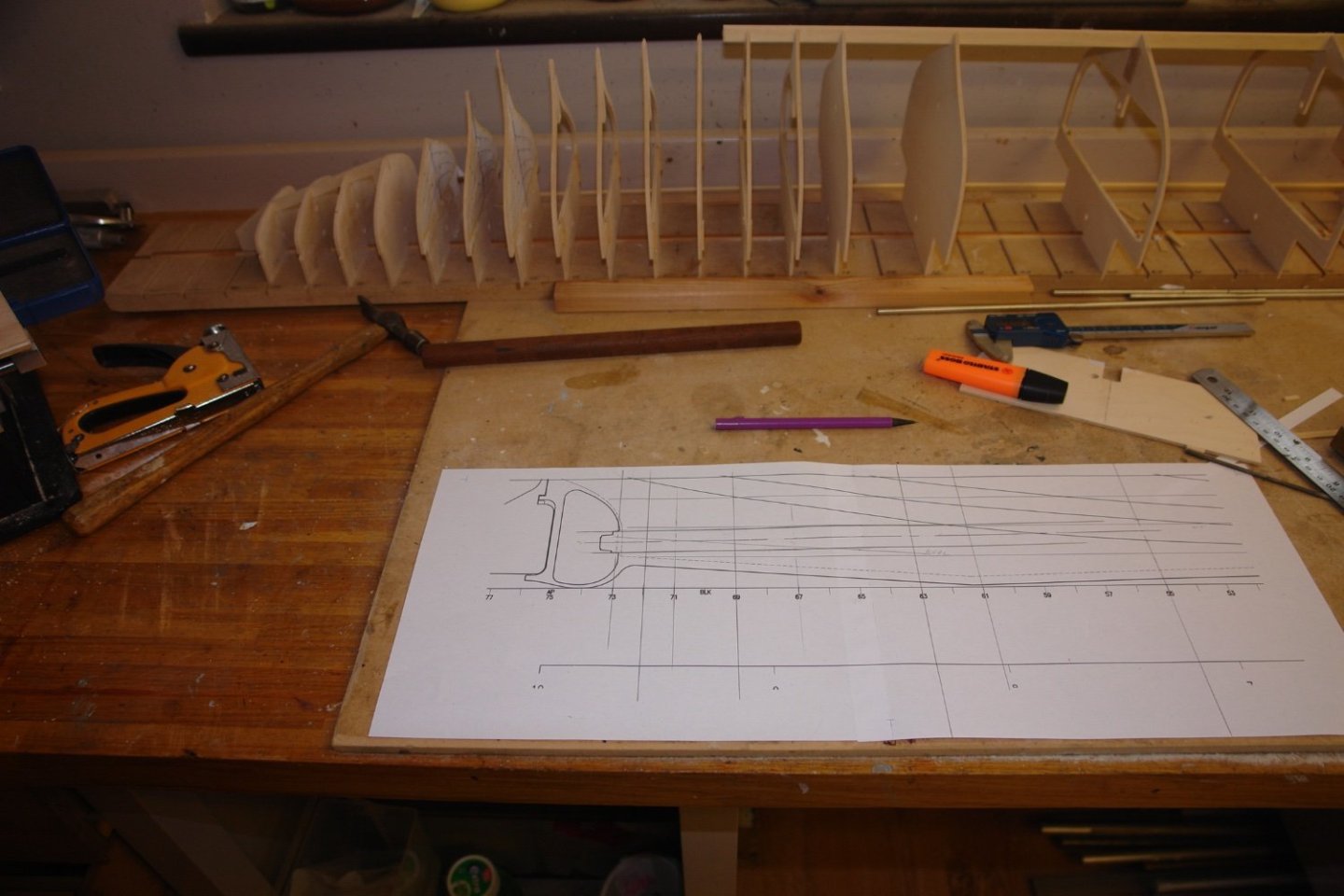
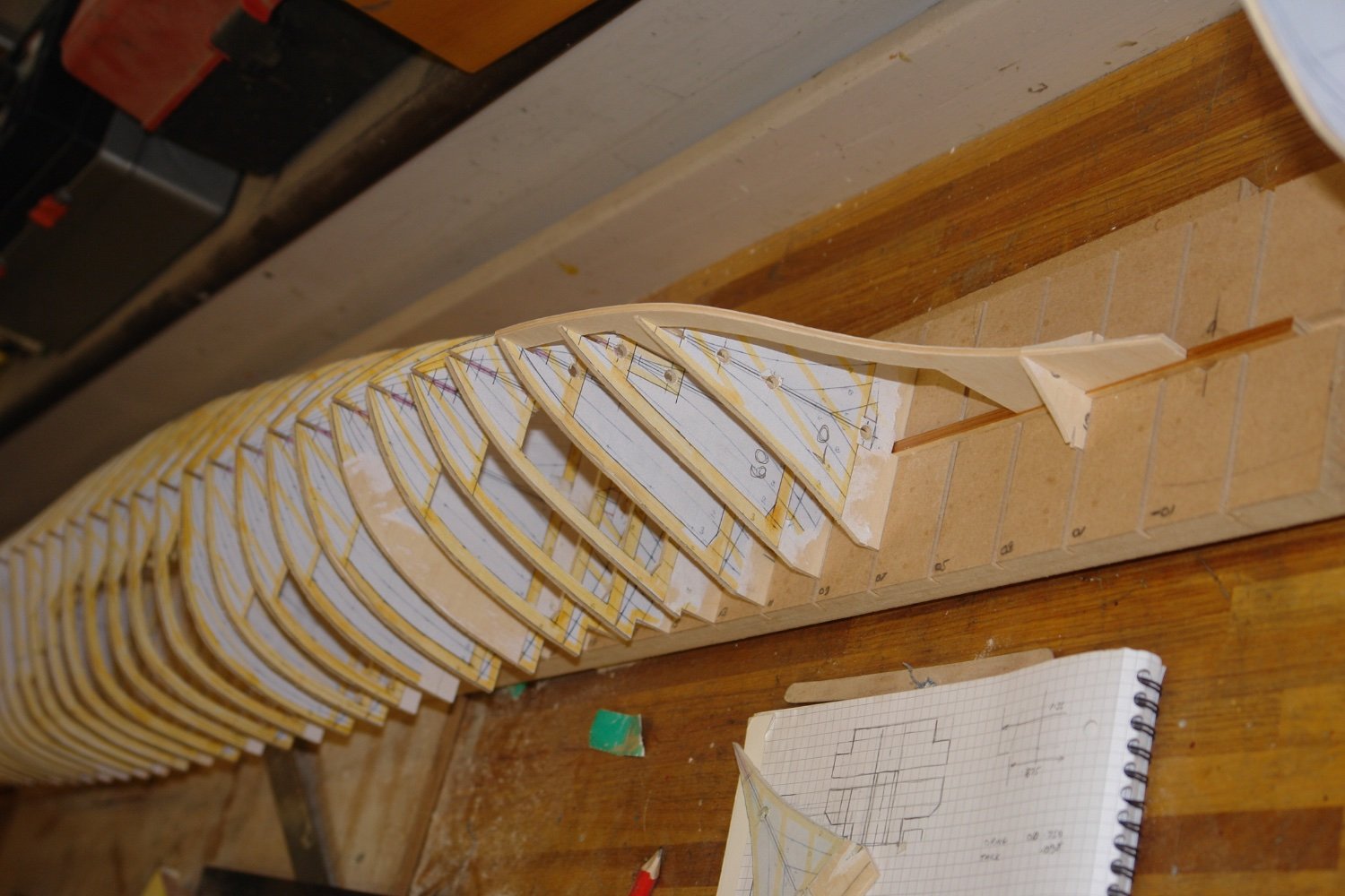
Bulkheads all now fixed to building board, keel made up and we are ready to start planking.

I have, of course, watched endless youtube clips about planking, so I am soaked in how to do it....but confused by the variations - everybody has their own methods.
So, what are the top tips for planking? The designer says to start at deck level and lay in a few planks either side of that. The lay in planks from the garboard and fill in the gap. Is that the best way?
-
I have come across a snag.
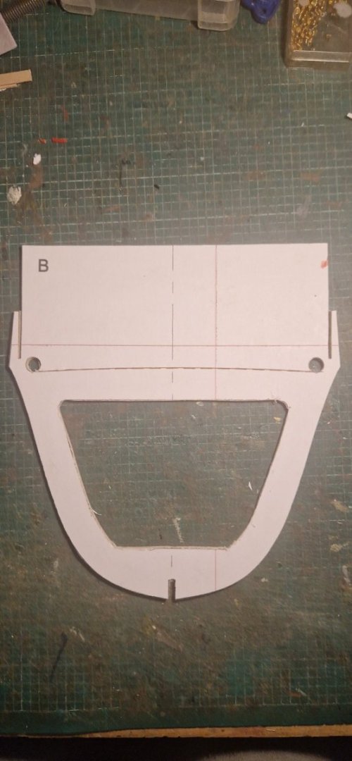
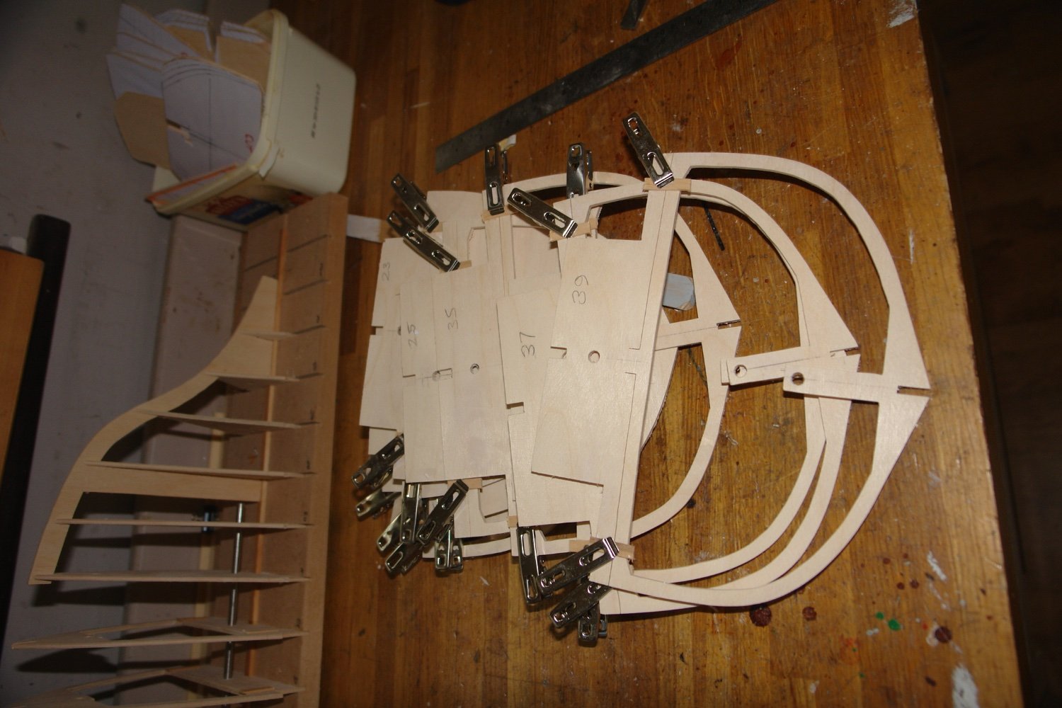
I have cut out the bulkheads exactly as per the drawings. When I assemble them, I have a mismatch between the hole for the propellor tube on the final bulkhead and where the cutout (slot) is on the keel section. See picture below
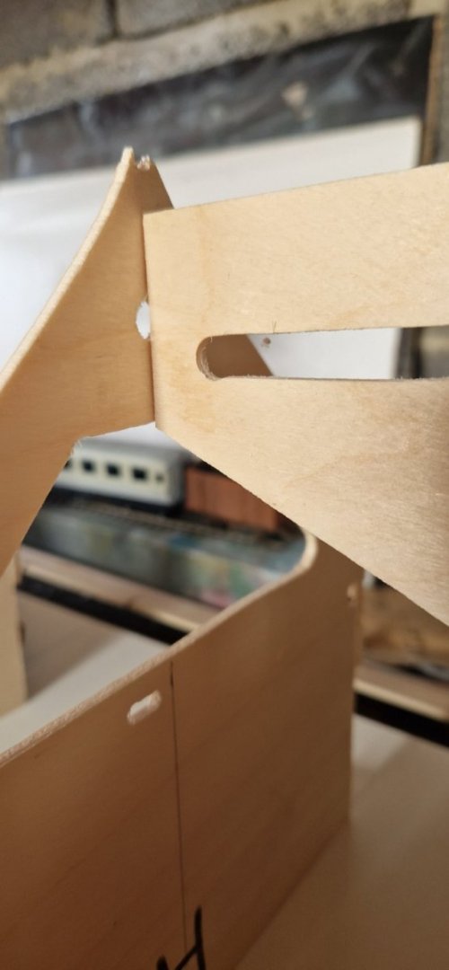
When I measure it on the drawings, I see the mismatch. There is a 8mm discrepancy, the diameter of the hole.
I don't see how I can change the slot because of I move it down the propeller will no longer fit.
All I can think of doing is to fill the holes in the bulkheads and refill them too match the slot. Then I'll need to shim the motor so that the shaft matches the redrilled holes.
Any thoughts?
-
12 hours ago, KeithAug said:
That is going to be quite a baptism of fire Ian. Do you have a lot of clamps? As you progress the planks need to align with the previous plank along their length. With a wide frame spacing you may find that the planks don't want to align with the previous plank particularly at the half way point between frames. You will probably need to clamp the adjacent planks together at mid span while the glue is drying. 3mm is quite thick for planks and they are going to take some restraining - presumably this is what the designer had in mind when he / she suggested balsa as the planking material. You may find other MSW members have more experience of large frame spacing with thick planks. They may be more able to comment and advise. Ultimately we all find a way in the end.
Hi Keith, thanks. We shall see. Luckily I can back out and change things if it doesn't work out. As you say, I said I was using balsa right up front and all the advice on here was not to, despite that being what the original designer used. I do have plenty of clamps, we shall just have to see how it goes.
I guess narrower planking will be easier than wider in that case.
Ian
-
-
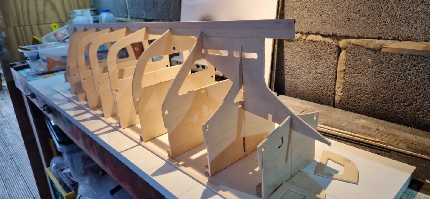
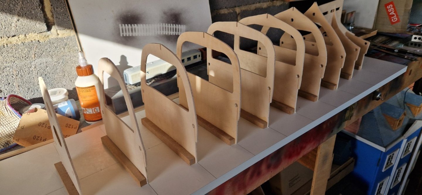
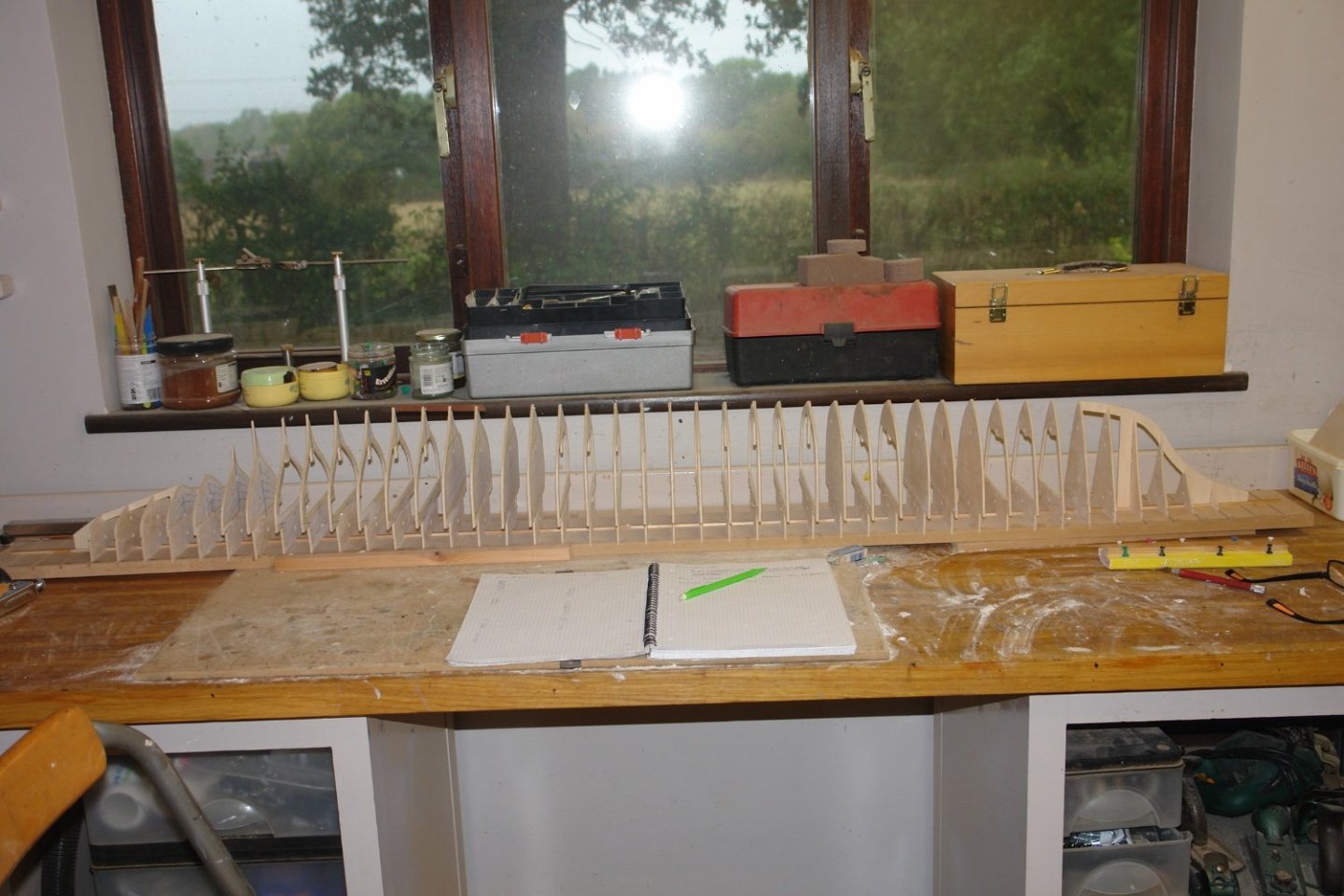
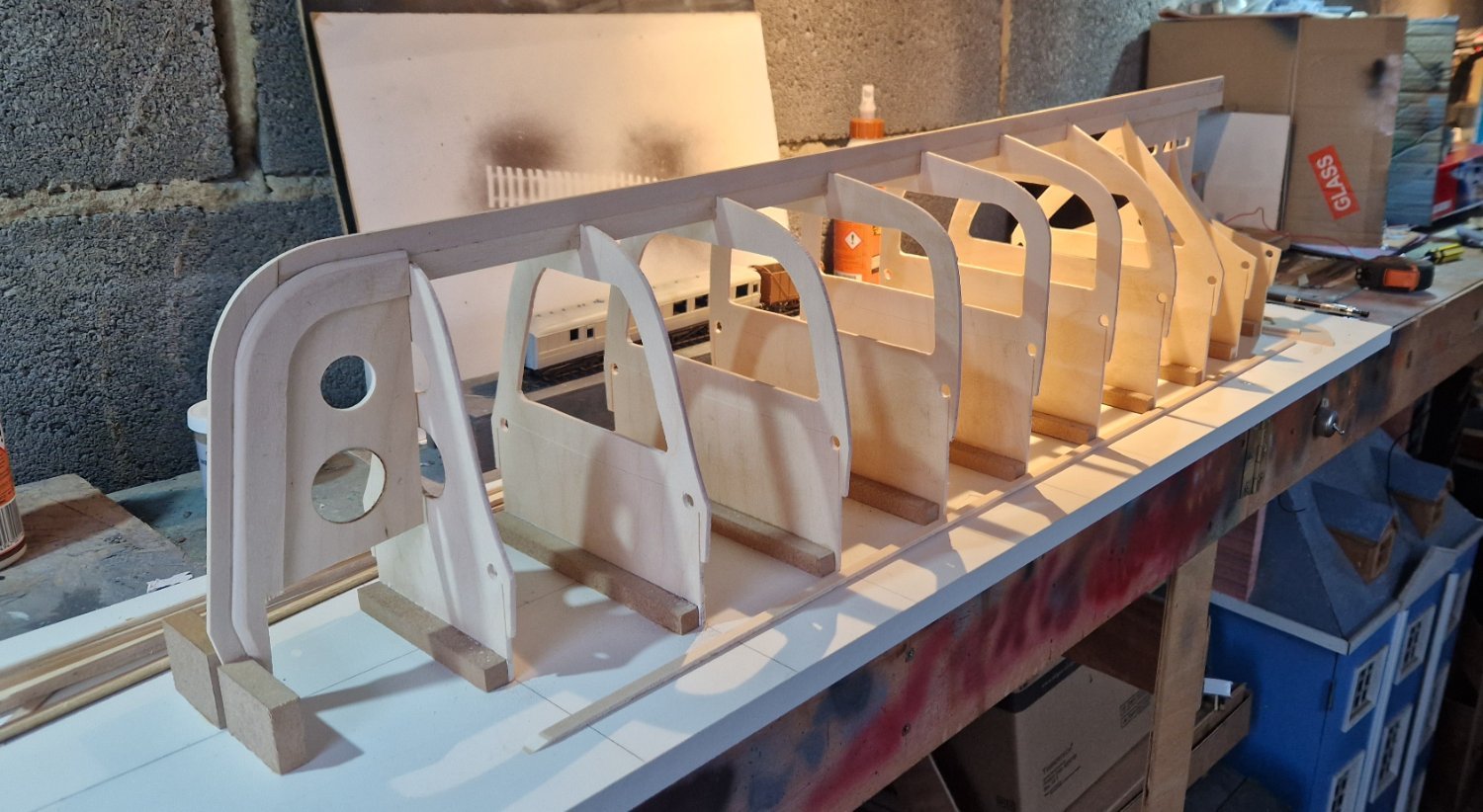
So I have now cut out all of the bulkheads.
Just temporarily stood up....
- Valeriy V, GrandpaPhil, FreekS and 2 others
-
 5
5
-
16 hours ago, wmherbert said:
I just finished a scratch build tug at 1/4 inch to foot. The hull was about 26 inches long. Since hull was going to be painted I tried using the widest planks I could. As you can see some were 1.5 inches wide along the bottom and the middle topsides. The stern took narrower planks but they were still over 1/4 inch. A midships there were only 4 planks total and at the front third only 3 planks total.
All and all it made the planking much faster and way easier to fair.
And when done and painted you can't see anything except a smooth hull.
Just an alternate thought.

Bill
Hi Bill that's very interesting, thanks.
-
12 hours ago, Roger Pellett said:
Ian, Planking a hull is a daunting problem for many modelers. The “correct” way to do it is to use a method called spiing. If done correctly it will provide a pleasing pattern for wooden ships/ models. You are not building a model of a wooden ship so you might want to explore a simpler planking method.
There is an alternate planking system for planking full sized watercraft. It is called Strip Planking. It is especially popular with builders of wooden Canoes. It involves planking a hull form of bulkheads with narrow strips of wood and then covering both the inside and outside of the hull with fiberglass. Sound familiar?
I have not seen this exact system used for models but it might have some applications. Try looking up strip built canoes on the Internet.
Roger
Hi Roger, thanks. Is "spiing" the correct term? Google doesn't help me with that!
The strip approach seems promising, I guess narrower strips are easier to form around the shape of the hull.
Ian
-
On 1/3/2024 at 6:01 PM, KeithAug said:
I am taking my time preparing stuff before I commit to the glue.
I sorted out the small frames at the bow and stern.

I spent a happy day stripping the cutting templates from the frames. I didn't find any of the usual solvents worked particularly well on pritt stick adhesive but peeling / sanding worked ok.
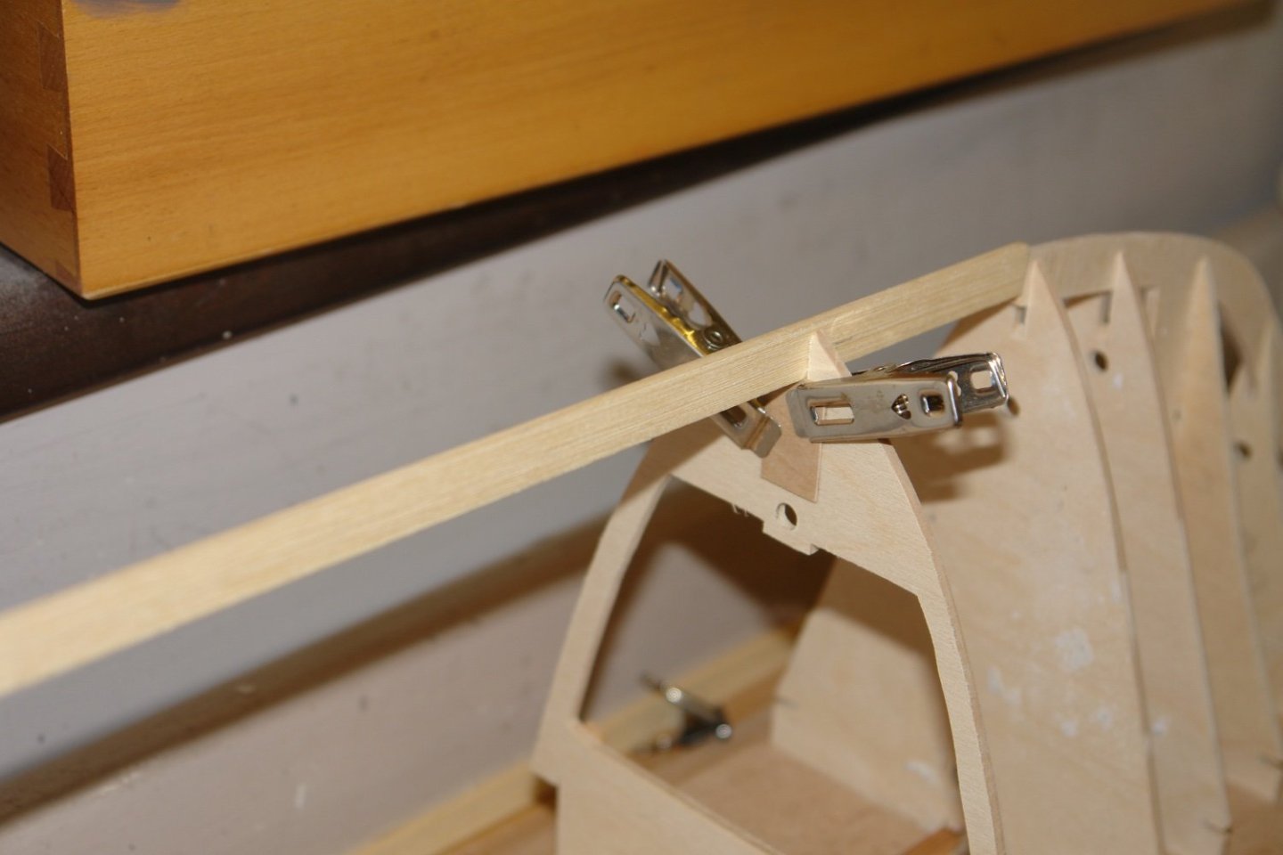
The cut line for the deck made the frames very flexible and I wanted them to be a little stiffer for the future hull sanding process. I therefore temporarily glued small strips of wood across the deck cut line to increase the stiffness.

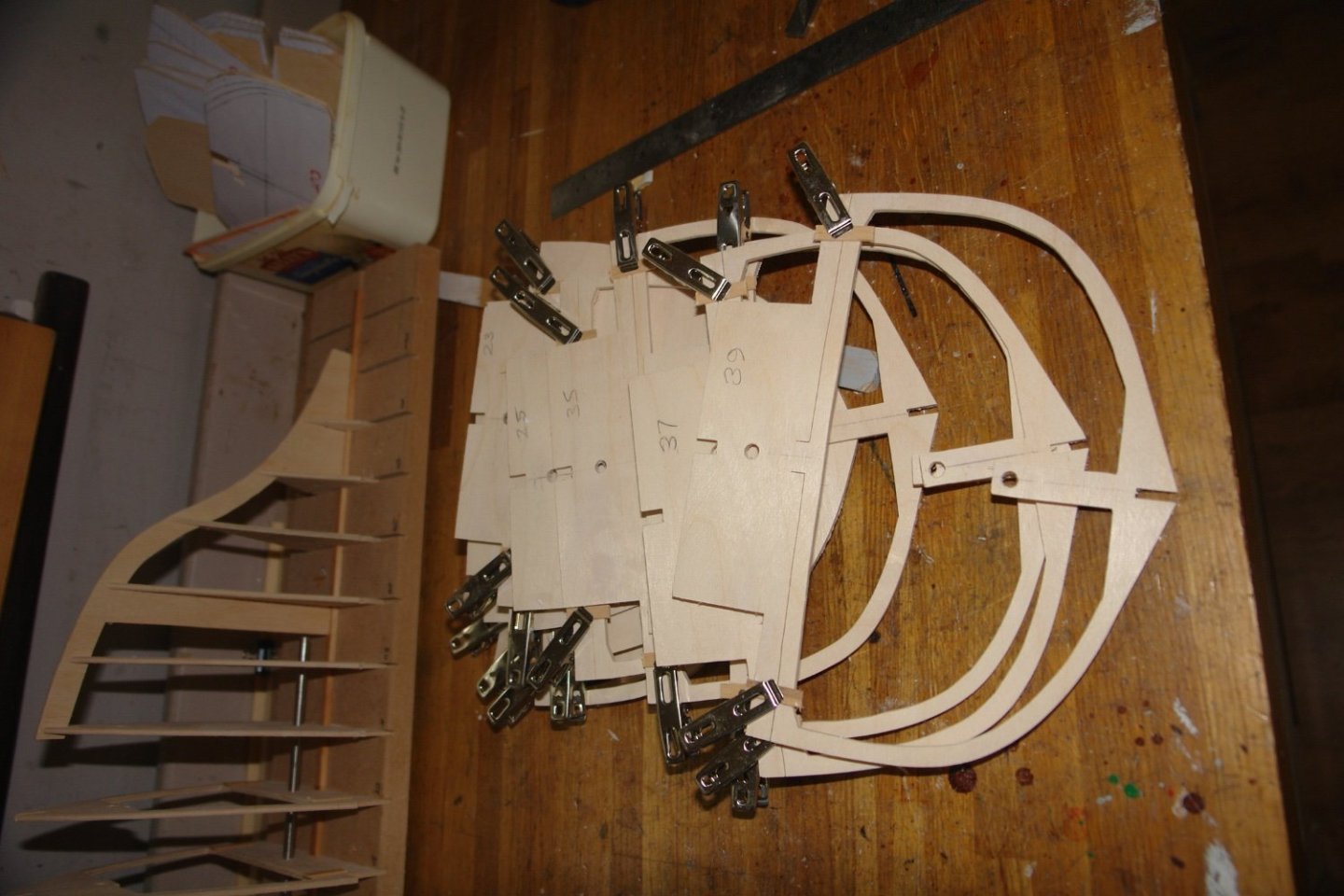
I also sorted out the correct vertical position of the keel. The keel slots were cut deeper than needed so I cut the keel strip and then assembled it into a few of the frames before setting it to the correct heights fore and aft. With friction holding the keel in place I glued tabs to the frames to fix the keel position.
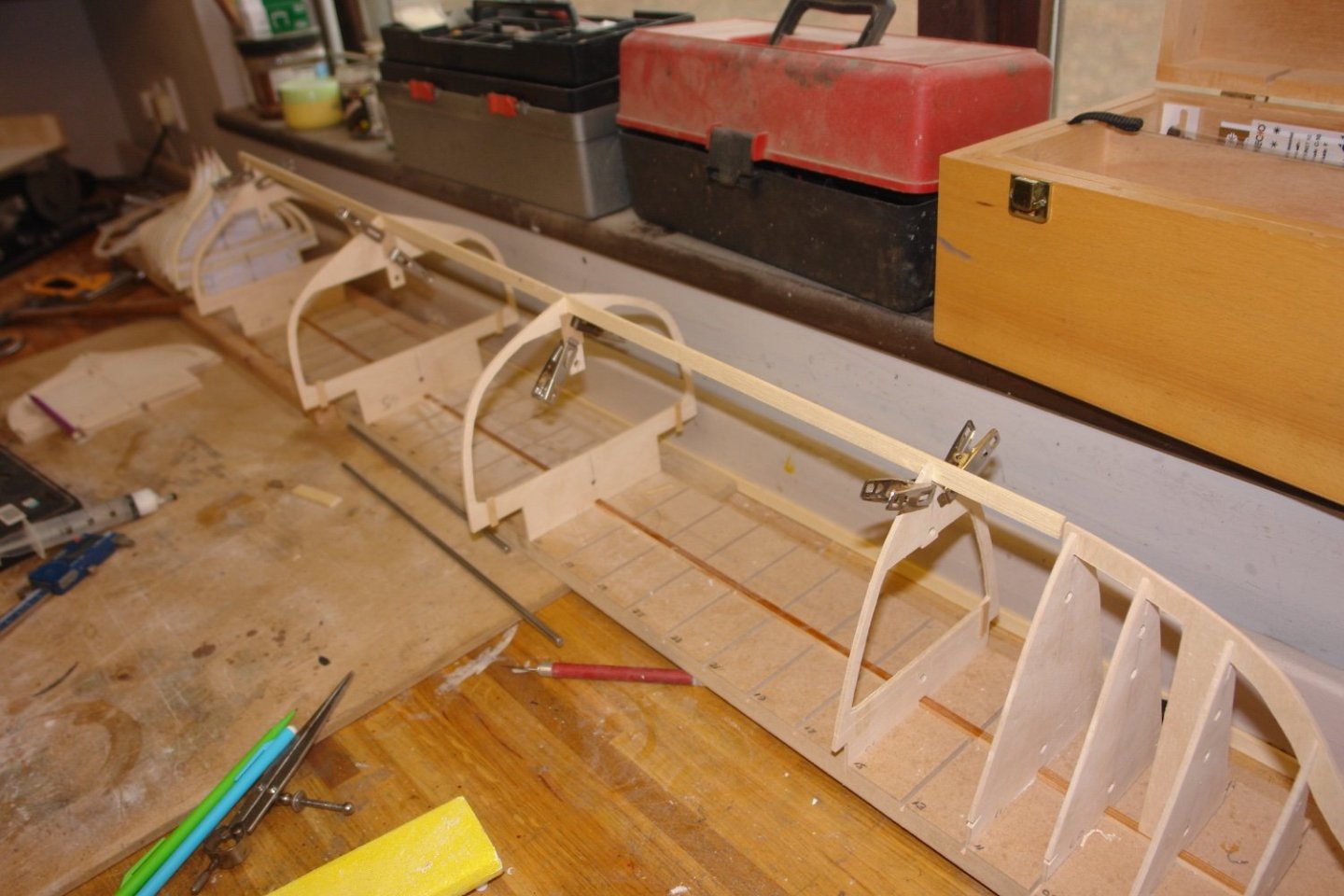
The line of the keel is broken at frame 61 and the next job is to sort out the position of the aft section of the keel.
Not very exciting but progress is progress.
Excellent. Very useful. I found that gentle heat from a hairdryer was sufficient to soften the prittstick such that it just peeled off.
- KeithAug, Retired guy, Keith Black and 2 others
-
5
-
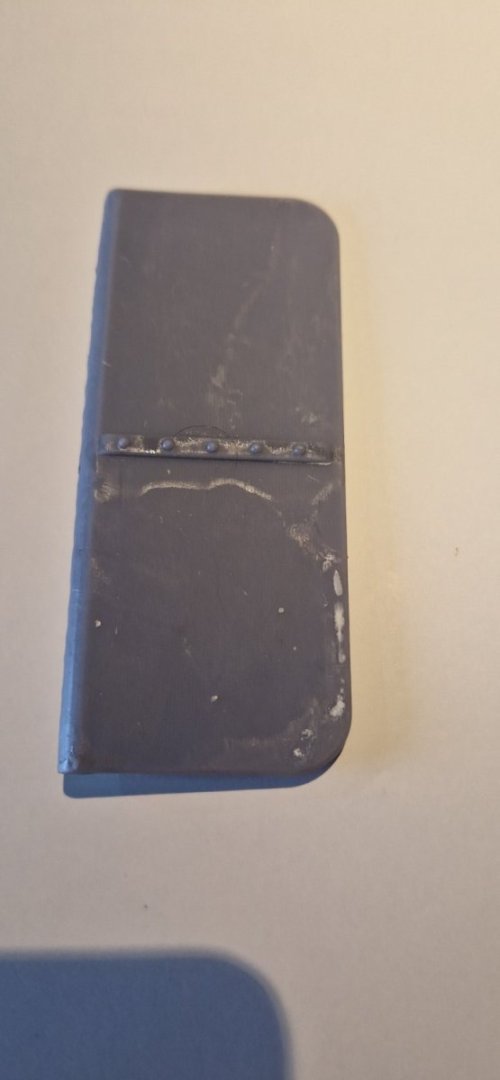
So the reprint was successful. I now have a straight, unwarped rudder. Ill upload a picture tomorrow.
Meantime i am still cutting out bulkheads.
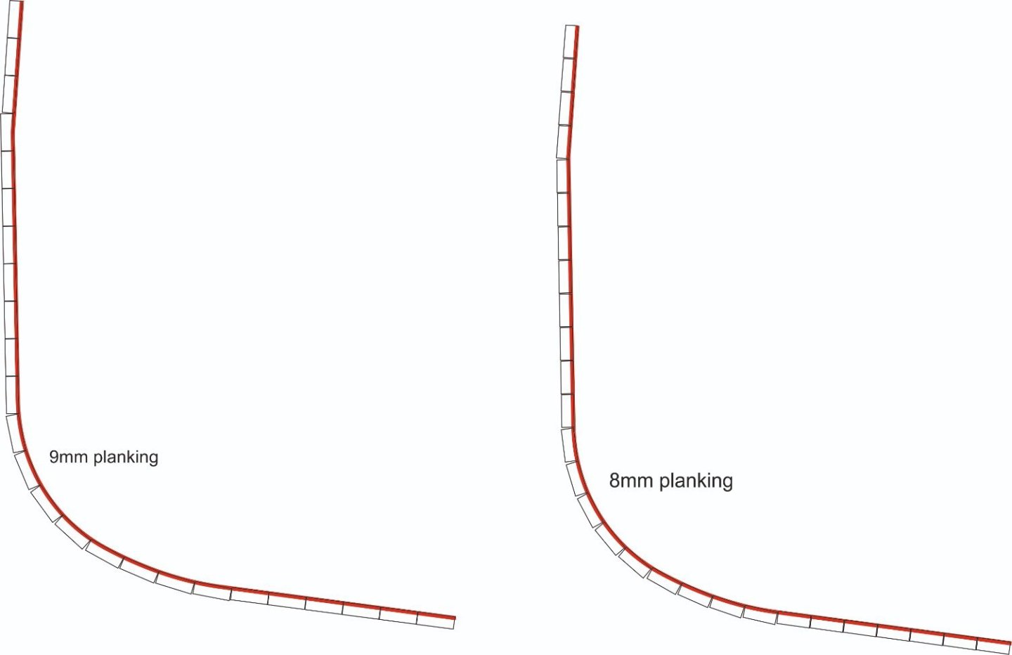
So a question, how do i decide the width of the planking? The drawings are silent on this, so its a bit of guess work.
The longest length from the gunwale to the keel is about 270mm.
here is a drawing showing 8mm and 9mm planking. I guess that where the sides are flat then its immaterial, but more important arouind the turns, and also where the planks bend around the stem and stern.
My temptation is to go for 8mm planking,
Any advice gratefully received.
-
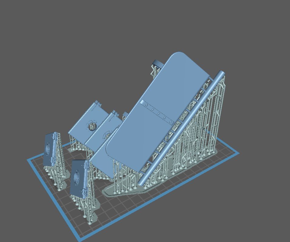
So tonight I am going to reprint the rudder. The screenshot below shows that I have added a sacrificial "sprue" along the bottom edge in order to try and keep the rudder from warping on the build plate. You can also see that I am going to print the remaining hatches and, hidden behind the rudder, is the motormount.
Its a 9 hour print, so Ill run it overnight. Lets hope this one is more successful....
- JerryTodd, FreekS and GrandpaPhil
-
3
-
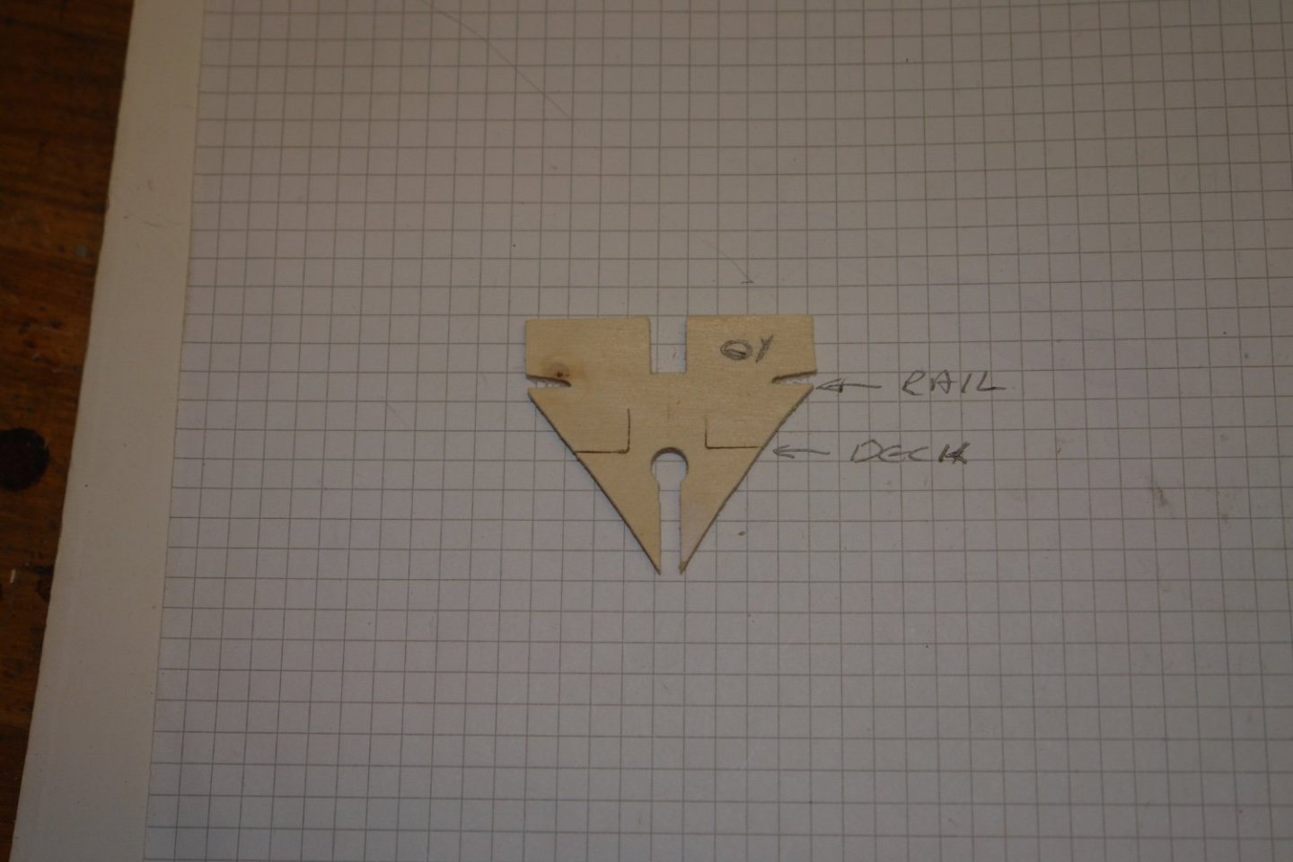
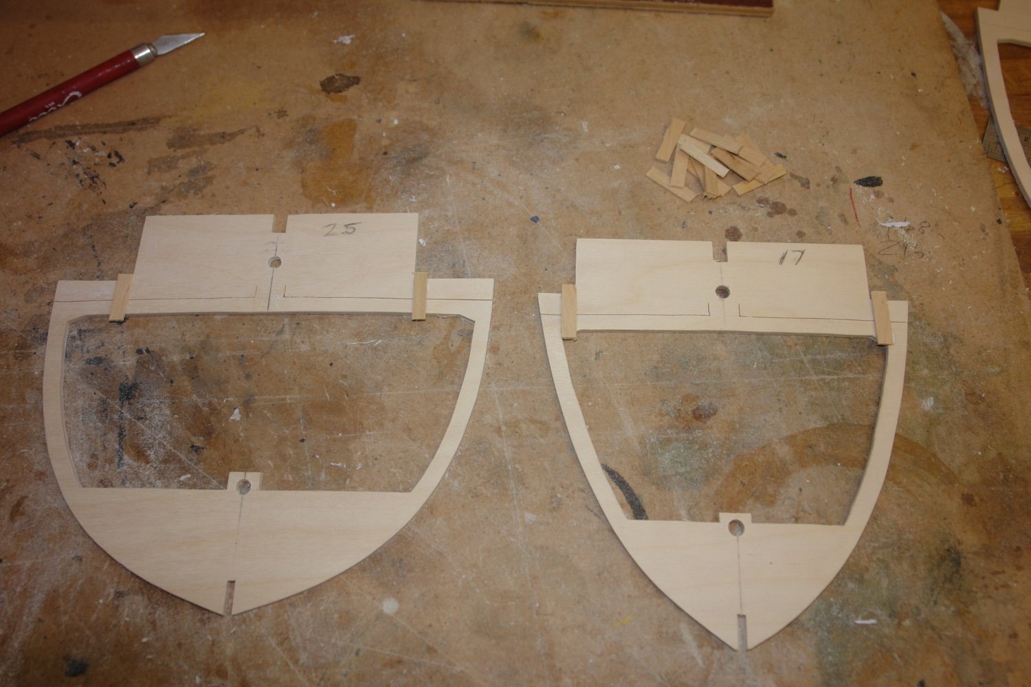
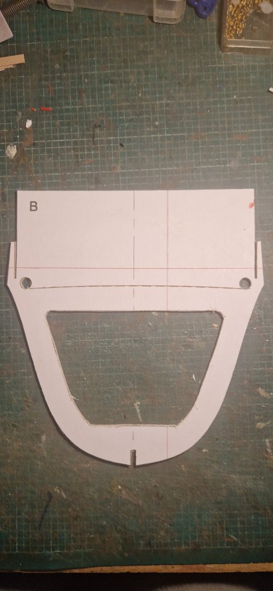
And I have also started cutting out the bulkheads....
This is the first one. The top edge is sacrificial and once the planking is complete, gets get off along the curved dashed line. The instructions say to "score this line" which I have done, probably cutting half way through. I am apprehensive as to how easy it's going to be to release the hull from the building board in this way. Anyone got any experience of this?
- GrandpaPhil and mtaylor
-
2
-
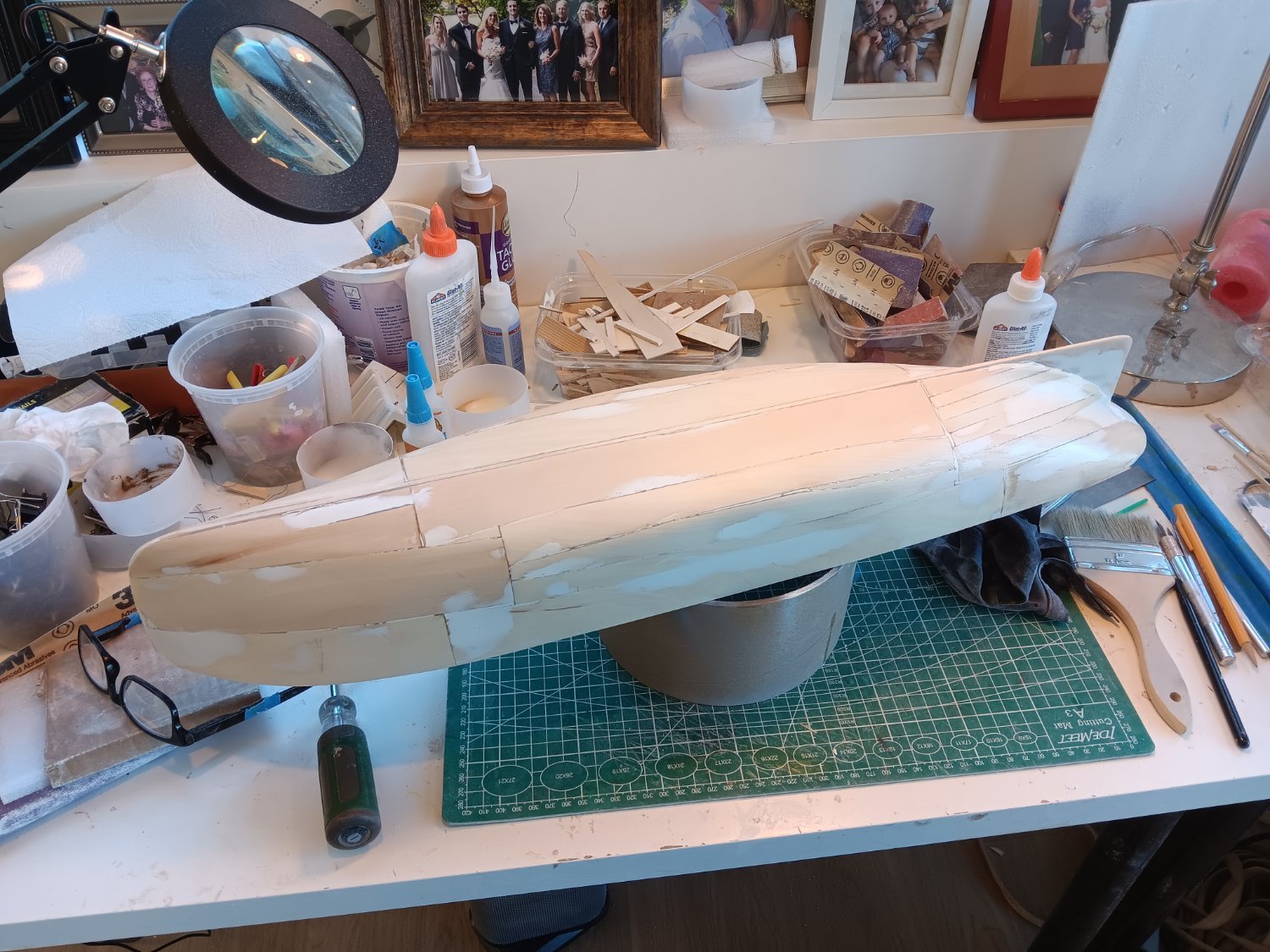
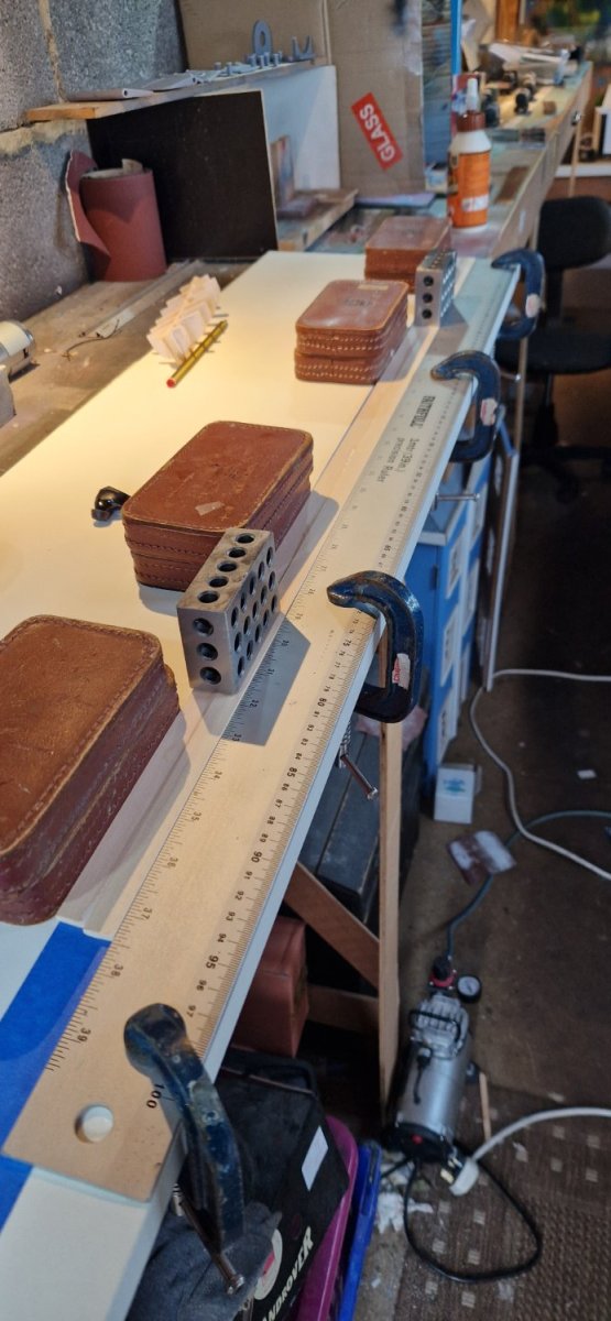
And so to actual construction. The keel is 25mm x 3mm basswood, but I could only buy 12.5mm x 3mm, so I have just to laminate two bits together.
I was concerned to get these true, they are 950mm long.
You can see the setup I used to get these glued true. I fastened down a 1m straight edge to my building board and held the wood tight with weights.

I held the wood flat with some 123 blocks.
Glue now drying.
- Rick310, mtaylor, GrandpaPhil and 1 other
-
4
-
So some progress.
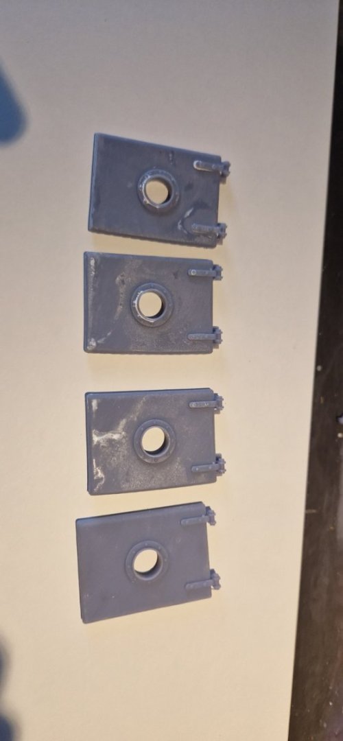
I think I can 3d print many of the fittings for the boat. I very much enjoy using fusion360 and I have used this to design a number of features. I have now printed some.
Below are the double bollards:
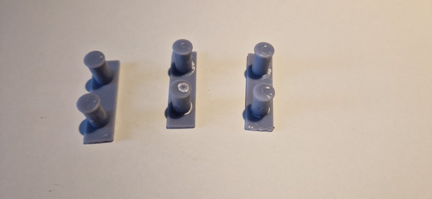
And here are engine room hatches with portholes built in.
And a failure. This is the rudder, but it has warped while printing. So I now need to reprint it, bit with additional supports to keep it true. The bend you see is not an optical illusion...
I have also designed funnel, portholes, skylight, vents etc. But not printed them yet.
More to came later.
Ian
-
7 hours ago, Roger Pellett said:
You’re probably going to have to make some calculations but I suspect that anything in the 1000’s of RPMs is way too fast. The RPM for the full sized tugboat would be something in the neighborhood of 75-90RPM. You need to consider the whole drive train including the motor’s speed torque curve with the propeller’s geometry and the resistance of the hull at various speeds. It wouldn’t surprise me if that prop stalls the motor.
Roger
Hi Roger thanks, I am not familiar with any of those sort of calculations and i know nothing about the motor's torque curve, the prop geometry or the hull resistance. Do people really make all of those sort of calculations for a model boat? if so, where do i find the info?
Bearing in mind its a 12v motor, if i link it up to 7.2v NiMH 5ampere batteries, then that should give slower revs and a reasonable duration?
- Keith Black, mtaylor and Canute
-
3
-
2 hours ago, FreekS said:
Nice build!
you will find (or calculate) that you will need quite a bit of ballast. Then lead-acid is fine provided it’s a sealed unit.
looks like you don’t need much current. If 1,5A works (test in bath for waves produced with that prop, the 5Ah would give you three hours of run time.
As there is no benefit for low weight and high currents of Lipo, stay away from them. I use them in subs where space is a premium.
I also successfully used 2x10 eneloop AAA to get 12-14V. Big advantage (these are a special type of NiMH) is that these have no memory and hold charge perfectly over storage.Finally, Li-ion also has lots of very good cells (3.7V 5000mAh).
If you make sure you speed controller has a low battery alarm than these are widely available and cheap.
something you do need to research is the match of the motor to the prop. 90mm props will put a lot of torque on the motor. For brushed motors rule of thumb is that diameter of motor should be about same as that of prop. For brushless that does not hold, the have massive power.Hi there thanks for the reply. My motor is 43mm diameter, so only half the diameter of the prop. I fear that a motor 90mm in diameter would be rather large!
- mtaylor, Keith Black and Canute
-
3
-
So I already have a motor in stock. It claims you be high torque, with the following specs:
Rated Voltage: 12-24V
Rated Current: 0.32 A
Rated Speed: 3500-10000 RPM (15000 RPM MAX)
Rated Power: 60W
I tested it this morning. Several wallwarts that were rated at 12v failed to shift it. Even though they claim to output 1amp or more. All I got was a couple of rotations, then a stall, then a few rotations etc.
I then connected up my beefy 12v old rheostat railway controller, rated at 1.5 amps. Motor ran perfectly, controllable and smooth.
I guess that the wall warts, even though claiming 1 amp current aren't up to the job...my electrical theory is letting me down.
But the real question is, how on earth do I choose a battery pack? I am told lipos are difficult to manage and I should steer clear of lead-acid. So that leads me back to NiMH.
what sort of rating do I need to get a decent run time?
YOu may think I am getting ahead of myself, but I need to know now what size of equipment the hull is going to have to accommodate so that I can make space as I cut the bulkheads.
- mtaylor and Keith Black
-
2
-
Nice price too!
- thibaultron, mtaylor and Canute
-
3
-
10 hours ago, gak1965 said:
Hi Ian,
I was going to use the spray glue, but my (probably quite ancient) can was not spraying. I would up using a bit of CA (it was there). Worked a charm.
Regards,
George
Hi George thanks. How easy was it to remove the templates from the wood after cutting out?
- Keith Black and mtaylor
-
2
-
Hi George, what did you decide on to stick the templates to the wood? I am at a similar stage to you on my build and am thinking prittstick.
Ian
- Keith Black and mtaylor
-
2
-
21 minutes ago, Jim Lad said:
She looks a fine little tug, mate.
By the way, I hate to be picky, but unless it's a trick of the light that looks like a left-handed propeller - like almost all single screw ships, 'Wattle' had a right-handed propeller.
John
Hi Jim yes it's a LH prop. I bought that as it was recommended by the designer. Apart from prototypical accuracy, does it make a difference?
- mtaylor, Canute and Keith Black
-
3
-
Well, my first purchase. Whilst I plan to make most of the parts myself, I thought that the prop would be beyond me. So now I am the proud owner of this
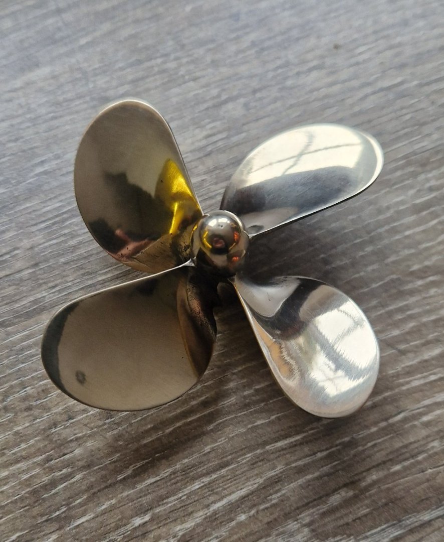
A bronze 90mm M5 prop.
I know I haven't even started on the hull yet, but thought I needed these things to get me started.
Ian
- Roger Pellett, yvesvidal, Canute and 4 others
-
7
-
11 hours ago, Jim Lad said:
Is this the Brisbane steam tug 'Wattle'?
John
Hi there John, it's the one currently based in Melbourne. https://baysteamersmaritimemuseum.org.au/5present.php
-
-
7 hours ago, KeithAug said:
Ian, ply is more difficult to sand than basswood but in principle there is no reason why it can't be used. I assume you don't have the means of cutting your own planks from basswood? You are going to find that the planks will need to tapered to fit on the frames - wider at the middle of the boat and narrower at stem and stern. Also to get smooth curve round the hull the need to be relatively narrow - probably no wider than 5mm. Some may need to be even narrower.
Hi Keith, i can cut any type of wood on the table saw. It's only that my local model shop (whom i like to support) doesn't list basswood on its website and I've not seen it in the store. Maybe i should go in and ask. I also read that basswood is "furry" - several quotes of this!
- Canute, Keith Black and mtaylor
-
3


Wattle by Ikcdab - 1:24 - Steam Tug - my first scratchbuild
in - Build logs for subjects built 1901 - Present Day
Posted
Thanks to @KeithAug @druxey and @wmherbert for your helpful advice. I'm not sure how I avoid bending "in the wide direction" as it seems essential to me that the first plank should follow the line of the deck.
With regards to my previous question about appropriate planking width, I realise that they don't all have to be the same width....I will get the table saw going tomorrow and cut planks in 6, 7 and 8mm widths and see how it goes ..
Thanks again