HOLIDAY DONATION DRIVE - SUPPORT MSW - DO YOUR PART TO KEEP THIS GREAT FORUM GOING! (Only 72 donations so far out of 49,000 members - Can we at least get 100? C'mon guys!)
×


cdrusn89
-
Posts
1,915 -
Joined
-
Last visited
Content Type
Profiles
Forums
Gallery
Events
Everything posted by cdrusn89
-
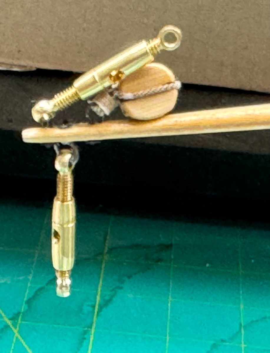
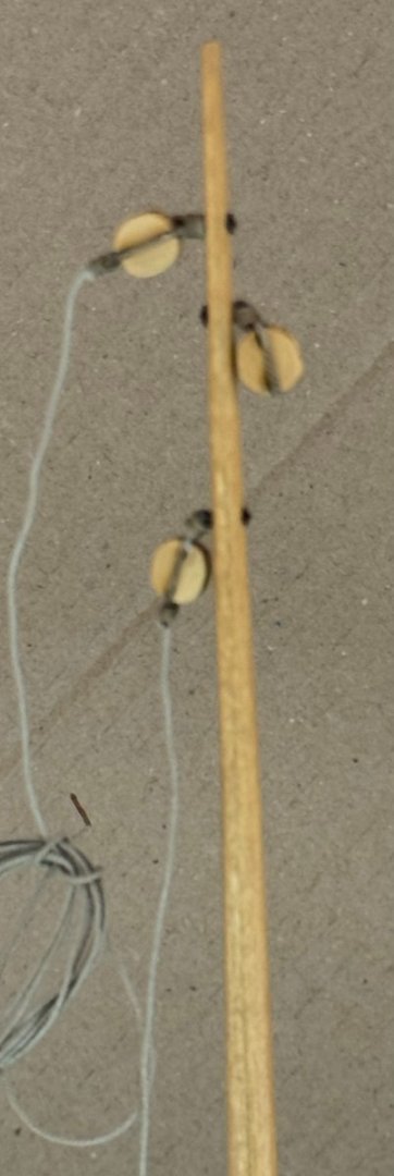
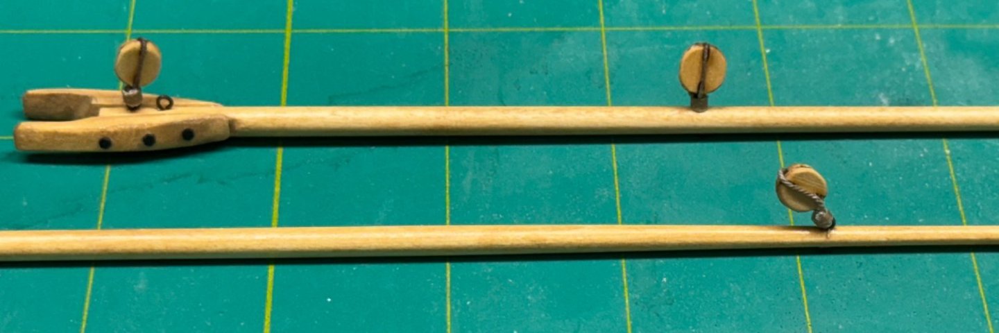
 I have the coaming and cabin sides in place and while waiting for the cabin roof to "dry and take shape" I started working on the rigging. I believe that one should attempt to get as much of the rigging as reasonably possible done before the spars are attached to the hull. To this end I attached the blocks to the boom and gaff. Attached the two blocks with lines attached and the single block to the mast. And the block and turnbuckles to the bowsprit. And yes you are correct those are not the kit provided turnbuckles - these actually work. Will come in handy to "tune" the rigging when that time comes. They are not cheap (~ $2.50 each) and are made by Caldercraft. Probably a bit out of scale here but would be about 2.5" in diameter at the widest point at full scale so not completely unreasonable (IMHO). I will probably chemically blacken them or at least tone down the shine before actually using them.
- 88 replies
-
- 3
-

-
- Muscongus Bay Lobster Smack
- Finished
- (and 1 more)
-
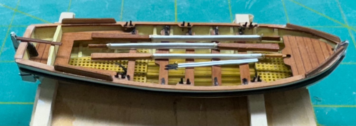
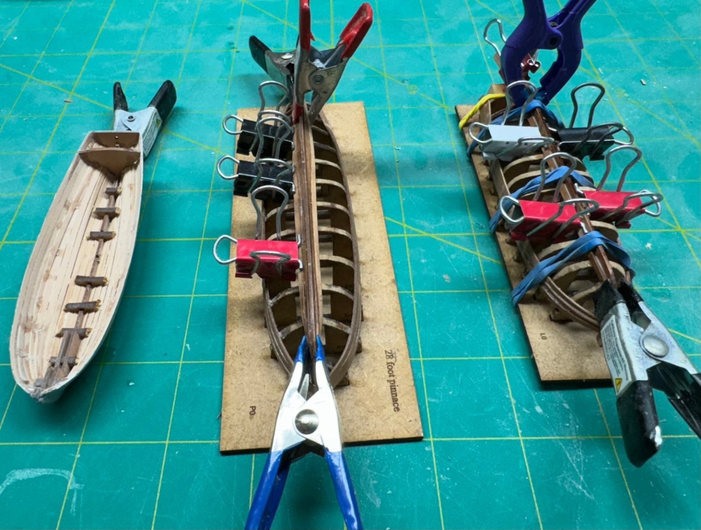
While working on the wales on the other two boats I wanted to make a recommendation for those who build these later. On both the Pinnance and Yawl the wales are located on top of the second plank down from the sheer. On the Launch they are on the sheer and the oar "locks" are created by short sections of planking above the sheer plank(s). So I recommend that on the Yawl and Pinnance that the wales be installed after painting the hull but before the seat installation and other interior "furnishing". Here is the Pinnance ready for seat installation: It will be much easier to get the clamps necessary to hold the wales down while the glue dries without the seats etc.getting in the way. Don't ask me how I came to this realization. On the Yawl I had to use clothes pins that were sanded down narrow enough to fit between the seats and they were not really strong enough to pull the wales into the hull curvature at the bow. I eventually had to soak the wales pieces and bend them on my duty plank bender to get them in place. So - add the wales on the Pinnance and Yawl BEFORE adding the seats etc.

- 422 replies
-
- 5
-
-
- Vanguard Models
- Sphinx
- (and 1 more)
-
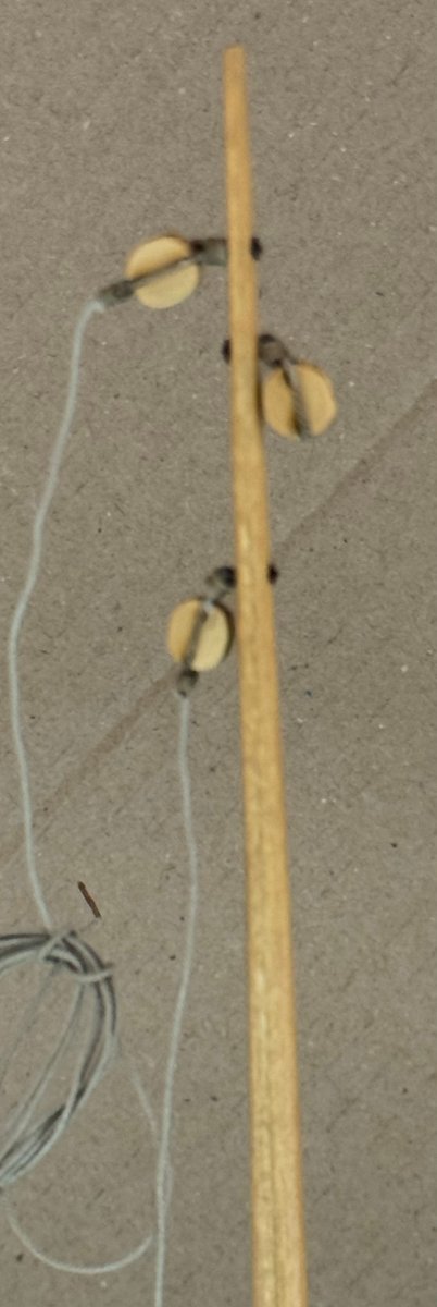
5/16" Boxwood blocks and 12mm Boxwood cleats with .025" phosphor bronze "pins" to increase stability. Some of these will actually have to sustain a load not just be ornamental. Blocks will be stropped with line rather than wire - I find it easier and neater and makes attaching them to an eyebolt easier. I have little faith in the holding power of PE or vinyl hooks. Both items are from Syren Ship Model Company.
- 88 replies
-
- 4
-
-
- Muscongus Bay Lobster Smack
- Finished
- (and 1 more)
-
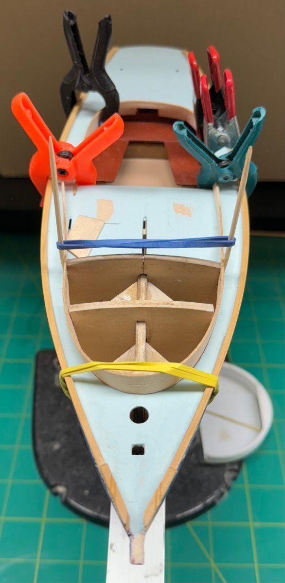
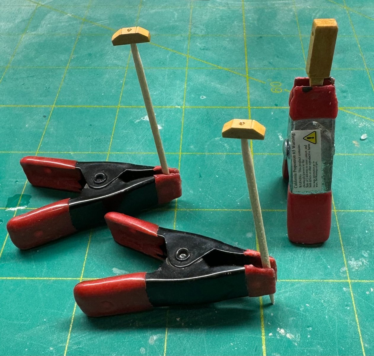
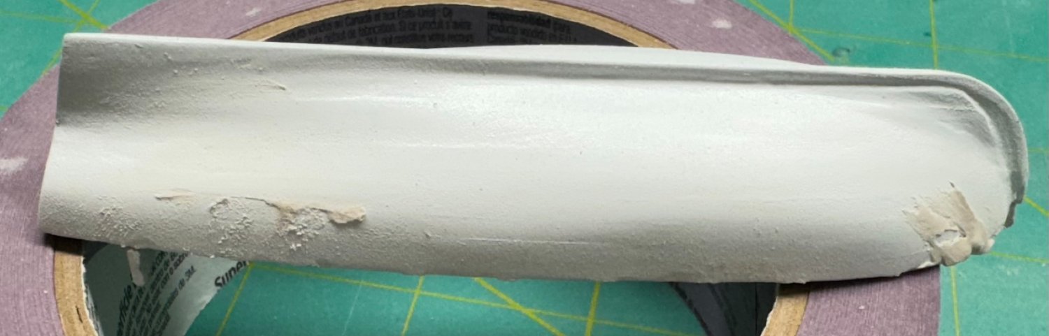
Cabin sides and coaming fitted and the coaming is glued in while the cabin sides are drying. Holding the cabin side down in front makes the sides want to flare out so the two toothpicks and rubber band are trying to keep them vertical. Paint scheme is still "under consideration". but I think cream inside the cockpit including the cabin front and access door (to match the floor) and the same light blue as the deck for the outsides of then coaming and the cabin walls. For the cabin roof I think white or off-white and maybe the cream or the dark blue for the cabin roof access slider and the tank tops.

- 88 replies
-
- 4
-
-
- Muscongus Bay Lobster Smack
- Finished
- (and 1 more)
-
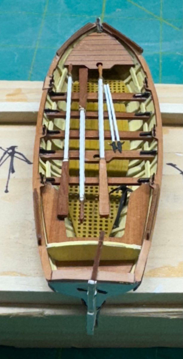
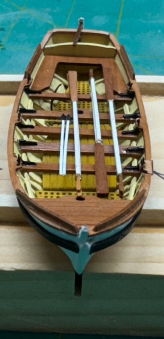
Yawl is DONE!!! Complete with anchor (and rode although you can't really see it, I know it is there), three sets of oars and two boat hooks. I seriously doubt that the boats were stored with the rudders in place - too hard to keep them secure and they are a very critical component but since the supplied rudder include integral pintles and gudgeons I decided to put the rudder on. Now if I can get the tiller to point dead ahead...


- 422 replies
-
- 6
-
-
- Vanguard Models
- Sphinx
- (and 1 more)
-
I have deferred installing the rub rail because I am not completely satisfied with the hull paint job and may do it over after the rest of the deck materials are installed - that is when the instructions would have you paint the hull anyway. So I fabricated new oarlock pads and Sampson post from boxwood to keep the topside materials consistent. Here they are after the first coat of WoP. I did notice that the oarlock pads pictured in the instructions appear to be considerably thinner than the ones provided which are about 3/32" tall. I also added the fair leads at the bow, also of boxwood - they still need WoP in the "grooves and at the rounded end aft. Working on the cabin coaming - I decided to try and get the coaming bent off the ship - I have a feeling that trying to get it both bent and fitted at the same time might be more problems than doing them one at a time.

- 88 replies
-
- 4
-
-
- Muscongus Bay Lobster Smack
- Finished
- (and 1 more)
-
I got the launch completed through the seat installation. Maybe tomorrow I will try and get the knees installed - 18 by my count (two on each side of the two seats where masts will be fitted). Should be much fun. I will paint the hull before installing the wales and the bulkhead supports at the oar locations - drawing would sure help to figure out where those are more exactly than just using the photos in the instructions!! Note - I broke (the gods of model ship building owe me another $1) the aft seat structure twice. I had to add a support under the second break to keep the two sides more or less level. My plan is to put all the oars in the center of the boat to hide the added support and hopefully where the two breaks are located. I also broke both of the seats with the mast cutouts but made replacements for those from the excess material on the carrier sheets. They need several more coats of WoP so they "match" the others.
- 422 replies
-
- 3
-
-
- Vanguard Models
- Sphinx
- (and 1 more)
-
Kurt - you are correct, glue the planks together edgewise and not to the frames. That presents something of a challenge in trying to get the planks to conform to the shape of the frames without attaching them. I suggest you invest in a bunch of rubber bands and some scrap sanding sticks to use as leverage to put pressure on. the planks while the glue (I used slightly diluted PVA) dries. I say sanding sticks because the sandpaper helps grip the planks. Otherwise the leverage sticks tend to slide in whatever direction the rubber bands pull them which, as luck would have it, is usually in an undesirable direction.
-
A word about knees. I had the devils own time getting them on the yawl. I painted them black (using a blunt Sharpie, easier and faster than paint), tried to get them in place with PVA but eventually settled for thin CA. Use a half needle applicator and hold the knee in place with the tweezers in one hand and the CA applicator in the other. They are very small and it is not obvious from the instructions which way (long side on seat or on bulkhead) they should go. I finally figured out it must be long side on the seat, otherwise they would stick up even more than they do, at least on mine. I have to assume that my seats are higher (but I carefully measured the directed 3mm down from the gunwale) or there is something else working here of which I am not aware. It would be really nice if there was a drawing of each of the boats somewhere. Where exactly the seats are supposed to go is "left to the student" with only the pictures in the instructions to go by. A drawing would also help locating the ribs. Spacing them 5-6mm apart per the instructions leaves a lot of room to both get out of sync between the two sides but also mess up the seat spacing. On the yawl I had to put seats where there were ribs which is not how it is supposed to work as best I can tell from the pictures. On the yawl I finally fixed the forward and rearward most seats from the pictures (but could easily be off a mm or two) measured the remaining distance and spaced the two middle seats so they are equally spaced. With six and seven seats on the other two boats that may not work as easily - I am poor at math. I just looked at the knees for the Launch and Pinnance and they are even smaller than on the yawl. And there are more of them; 14 on the Pinnance and 16 on the Launch. I am considering gluing them on the seats before they are installed on the boat and not painting them black like in the instructions but leave them "natural," laser char and all - I can't imagine trying to get the char off something sooooo small).)
- 422 replies
-
- 1
-
-
- Vanguard Models
- Sphinx
- (and 1 more)
-
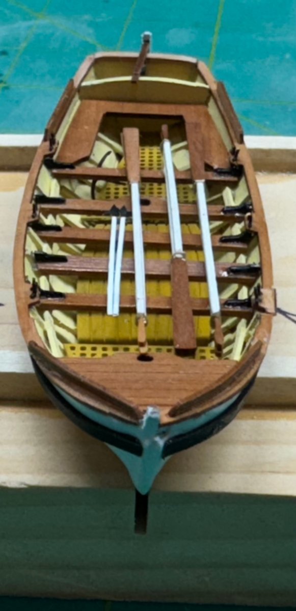
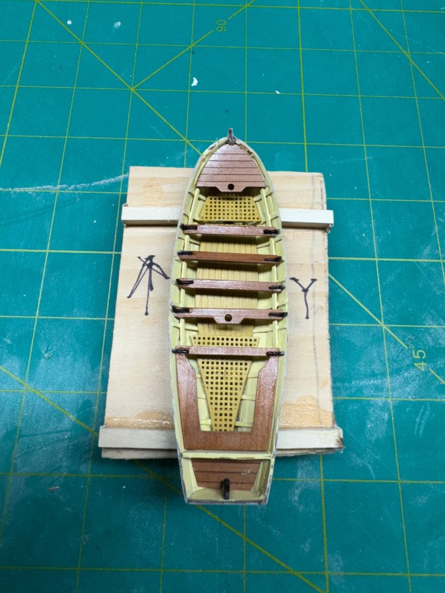
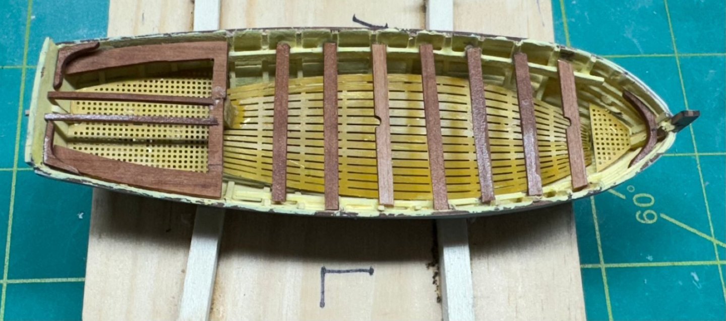
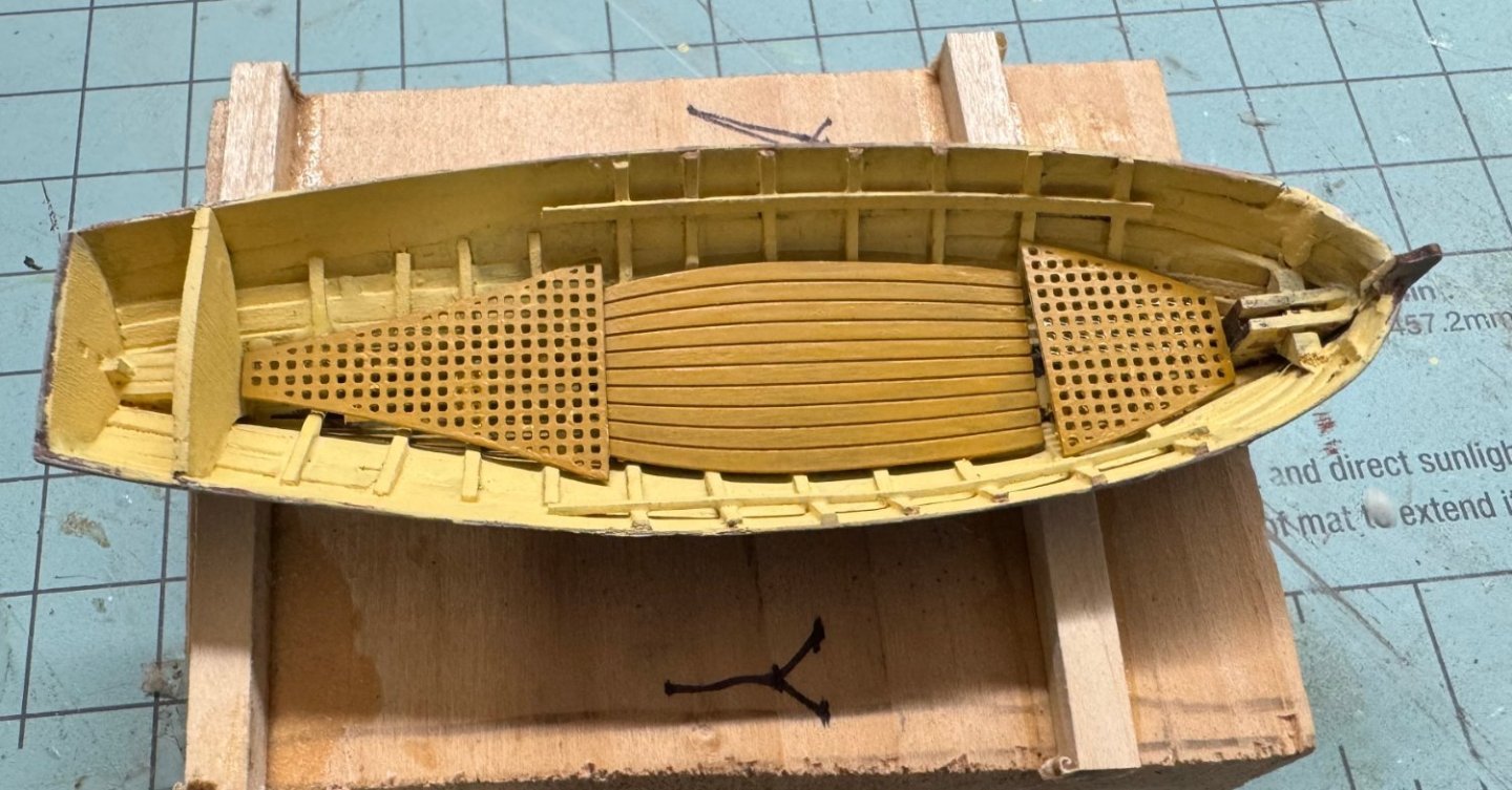
The yawl with the seats and such installed. And yes I know that gloss finishes were not used in this time period but I could not resist some shiny surfaces - it is a boat after all. Next is the gunwales on each side and the stern then then hull paint and wales. The Launch and Pinnance are coming along nicely.


- 422 replies
-
- 4
-
-
- Vanguard Models
- Sphinx
- (and 1 more)
-
Kurt - I have started building Sphinx (my first vanguard kit) but started on the ship's boats. I did not want to get to the end and then have to build the boats to finish. I followed a similar strategy on Confederacy and Winchelsea (although the ship's boat was not part of the original Winchelsea "kit"). Perhaps I am just to set in my ways. I will let you "lead the way" going forward.
-
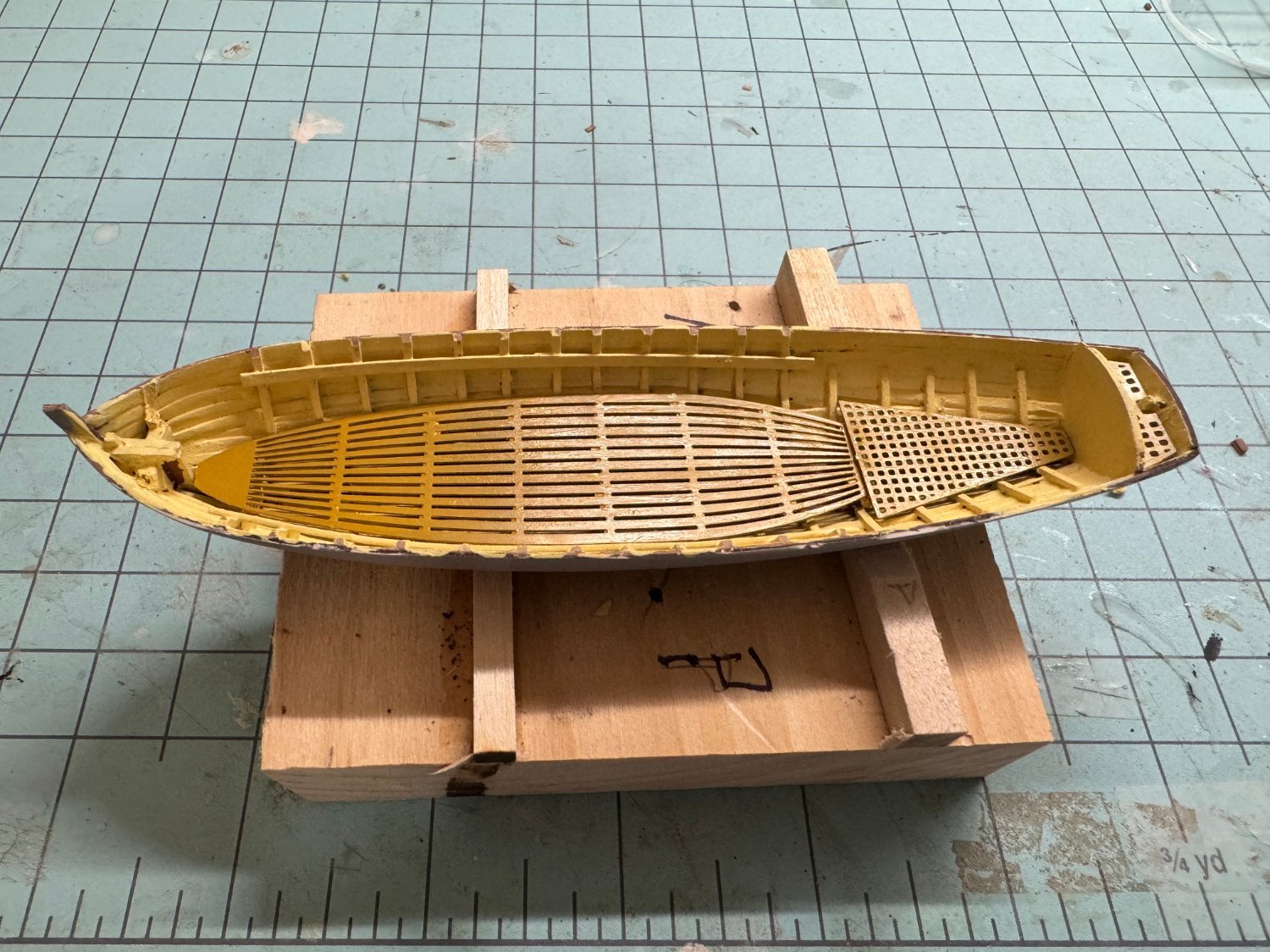
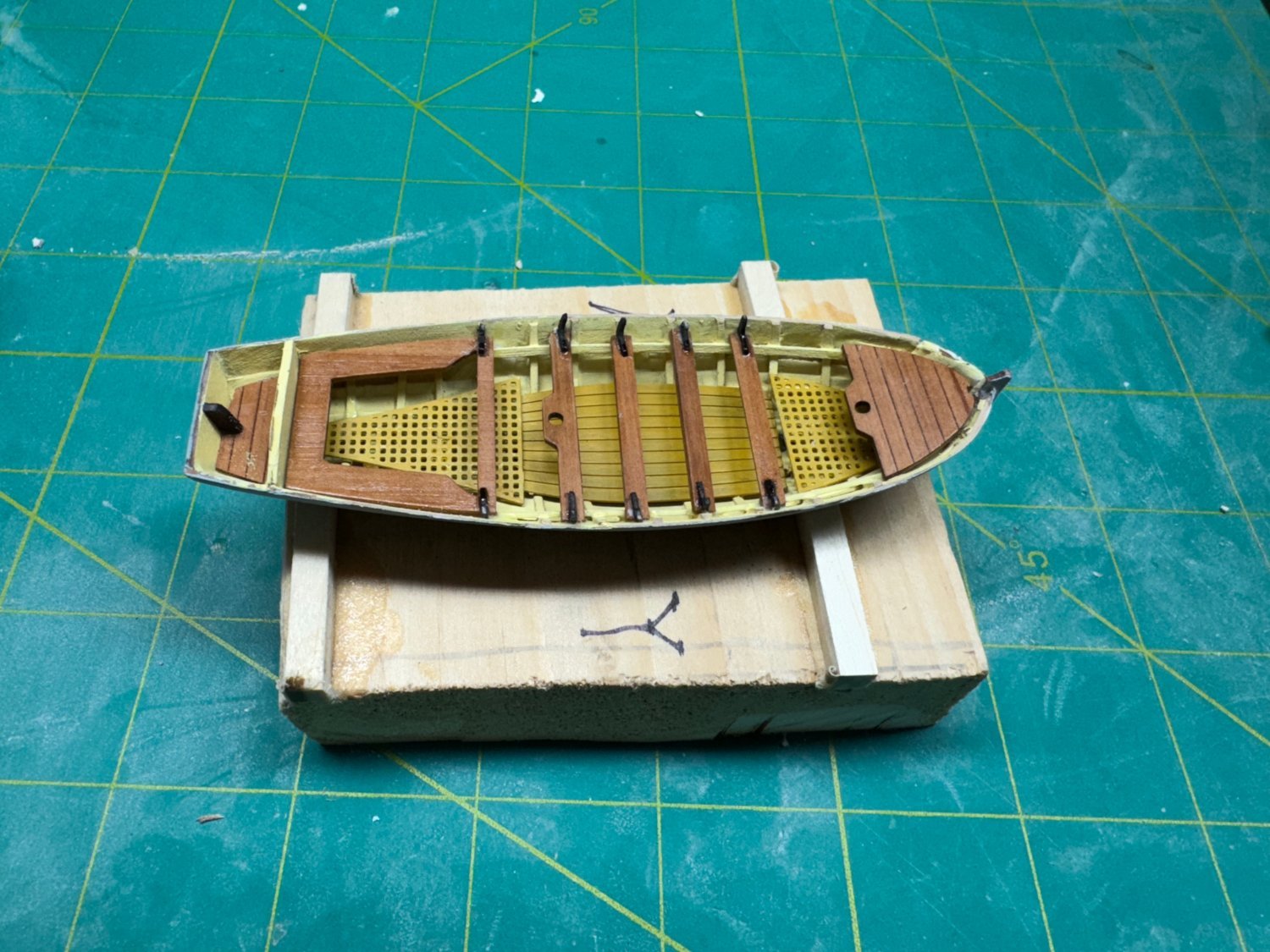
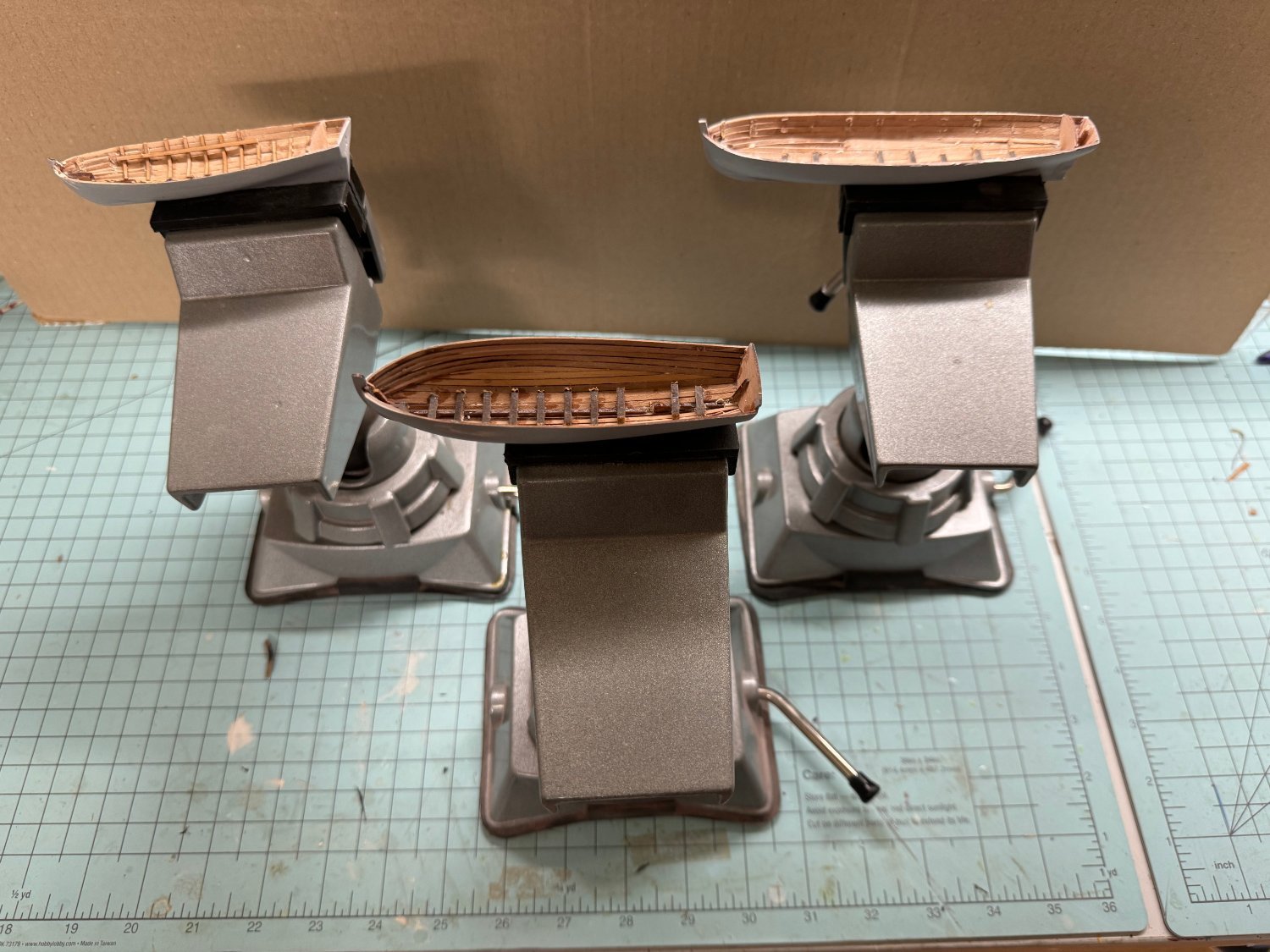
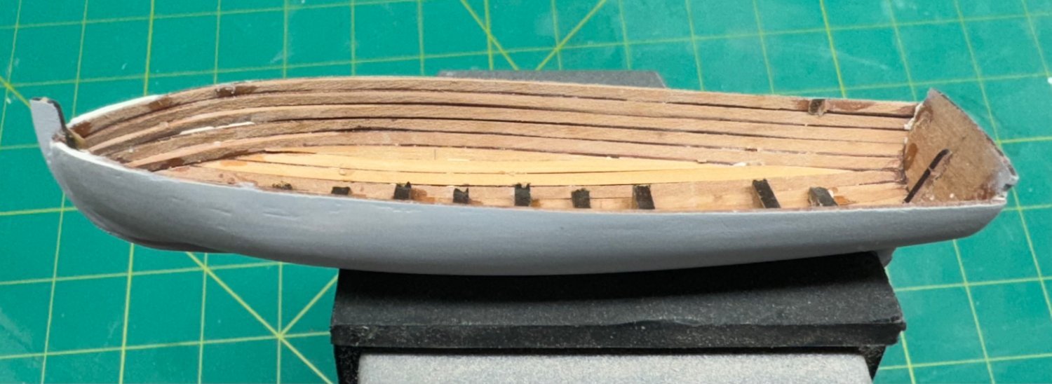
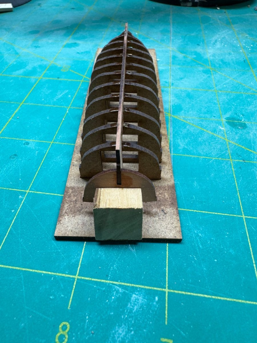
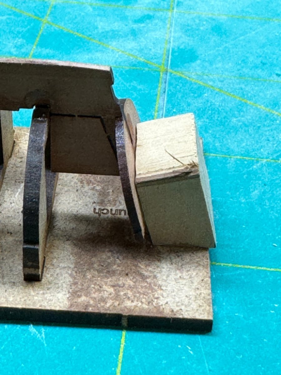
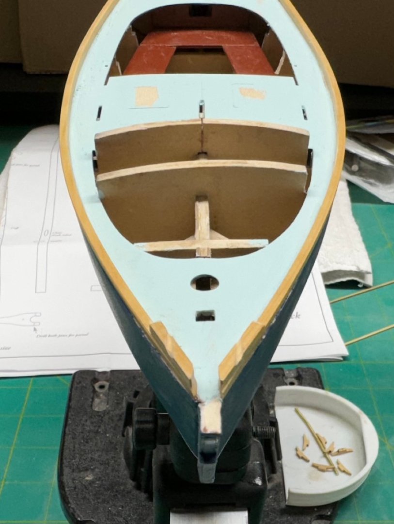
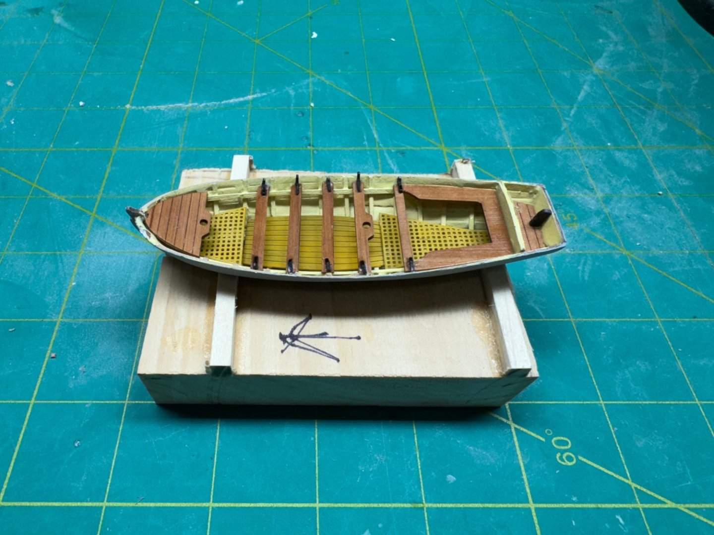
Much as would have liked the suction vises to adequately hold the boats such was not the case. Try as I might they would not stay secure or even a reasonable approximation of secure while I added the ribs. So I resorted to more "primitive" methods. I cut a slot in a scrap piece of wood, fashioned some supports from square stock scraps and there is the yawl base. Y = yawl and the arrow points forward since the supports are "tailored" to some extent. Since the hulls do not yet have there finish coat of paint I use rubber cement to attach the hull to the base. And here is the yawl after interior painting and floorboard installation.

- 422 replies
-
- 2
-
-
- Vanguard Models
- Sphinx
- (and 1 more)
-
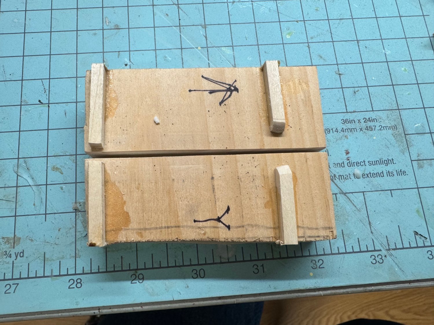
So here they are ready for ribs, seat supports and floorboards. The vises will hold them but only if the are placed with the stern near one end - the keel is not tall enough for the vise jaws to grab once you get more than a third the way forward. Don't ask why I have three of the vises - that is a whole "other story".

- 422 replies
-
- 3
-
-
- Vanguard Models
- Sphinx
- (and 1 more)
-
I guess you can't have everything. The pinnance only lost 2 1/2 bulkheads. But the interior sides are going to take some work to get the glue residue off.
- 422 replies
-
- 3
-
-
- Vanguard Models
- Sphinx
- (and 1 more)
-
They say it is an ill wind that blows nobody good and here is an example. Because the bulkheads were not glued in very well and I took some pain in the planking to try and avoid gluing the planks to the bulkheads the interior clean-up took no time at all. Except where the filler came inside (my planking skills are obviously not all that great) there was little to do. Hopefully the pinnance will be similar, except the bottoms of the bulkheads stay attached to the keel.

- 422 replies
-
- 3
-
-
- Vanguard Models
- Sphinx
- (and 1 more)
-
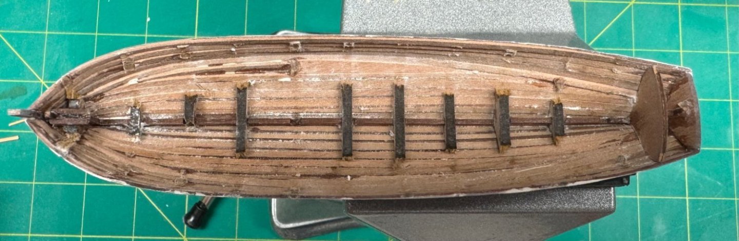
I got the launch hull "good enough" I went to remove the bulkheads and except for a part of bulkhead 1 ALL of the other bulkheads came out in their entirety. So much for my gluing technique attaching the bulkheads to the keel. I am busy cutting the bulkheads apart and gluing the lower part to the keel/hull. They are needed I suppose to keep the bottom of the hull stiff and support the floorboards. Hopefully I did a better job on the pinnance which is ready to have its bulkheads removed.
- 422 replies
-
- 3
-
-
- Vanguard Models
- Sphinx
- (and 1 more)
-
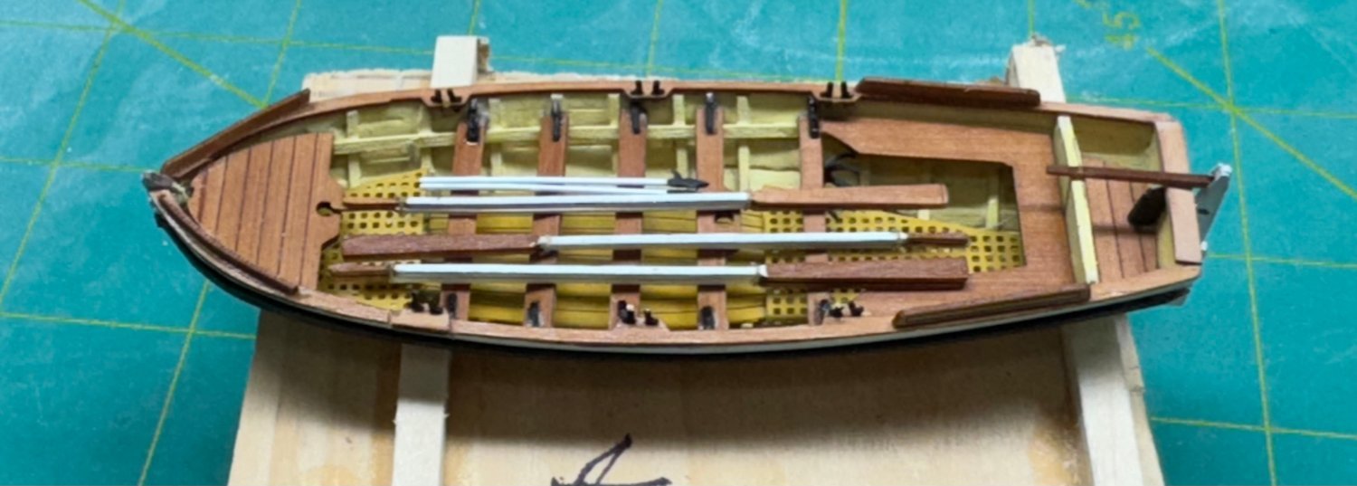
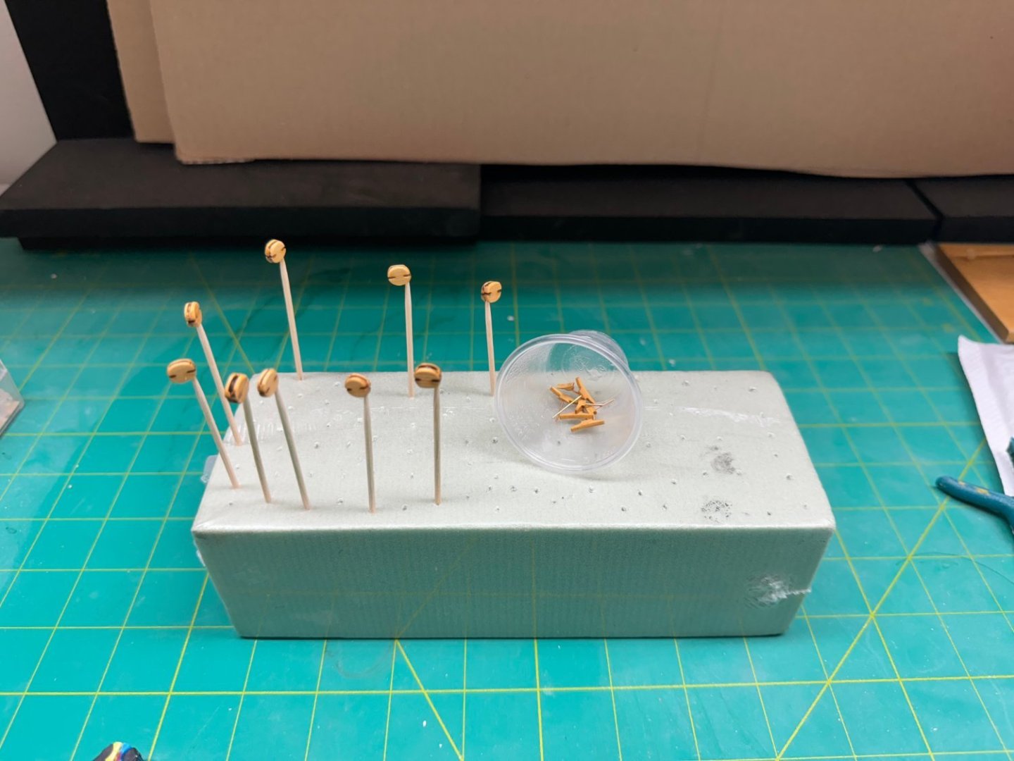
I have decided (for no particular reason other than personal preference) to bring all three boat hulls to the same place in the construction process before proceeding further with the yawl hull which is awaiting the floor board installation. This means finishing the hull planking on the pinnance and launch and then getting the hulls smoothed out ready for painting. Since this is going to require several cycles of "fill & sand" I filled the waiting time by getting the oars ready although they, like the boats will not be anywhere but storage for the next year or more. The oars are laser cut on the 1mm carrier sheet. I believe there are at least 48 oars provided although I doubt there would be more than 24 needed; 6 in yawl, 8 in launch and 10 or 12 in the pinnance - I say this without counting oar locks I doubt more than 6 or 8 would actually be placed in the boats for display. Anyway it is a good thing so many are provided as once removed from the carrier sheet they are very fragile especially where the handle meets the shaft. Trying to get the laser char off and get some semblance of "roundness" on the 1mm square (more or less) shaft and the even smaller handle led to more than a few oars ending up in the trash. Partially my fault for deciding to have the blade and handle natural and the shaft white. Although I did not try it I suspect that painting over the char might lead to fewer "rejects". So, here with two coats of Badger 16-417 White paint on the shafts and two coats of WoP (applied with a brush - trying to wipe it on with a rag would result in more casualties) are 30 oars.
- 422 replies
-
- 4
-
-
- Vanguard Models
- Sphinx
- (and 1 more)
-
Thanks Eric - appreciate the speedy response.
- 62 replies
-
- 2
-
-
- Muscongus Bay Lobster Smack
- Model Shipways
- (and 1 more)
-
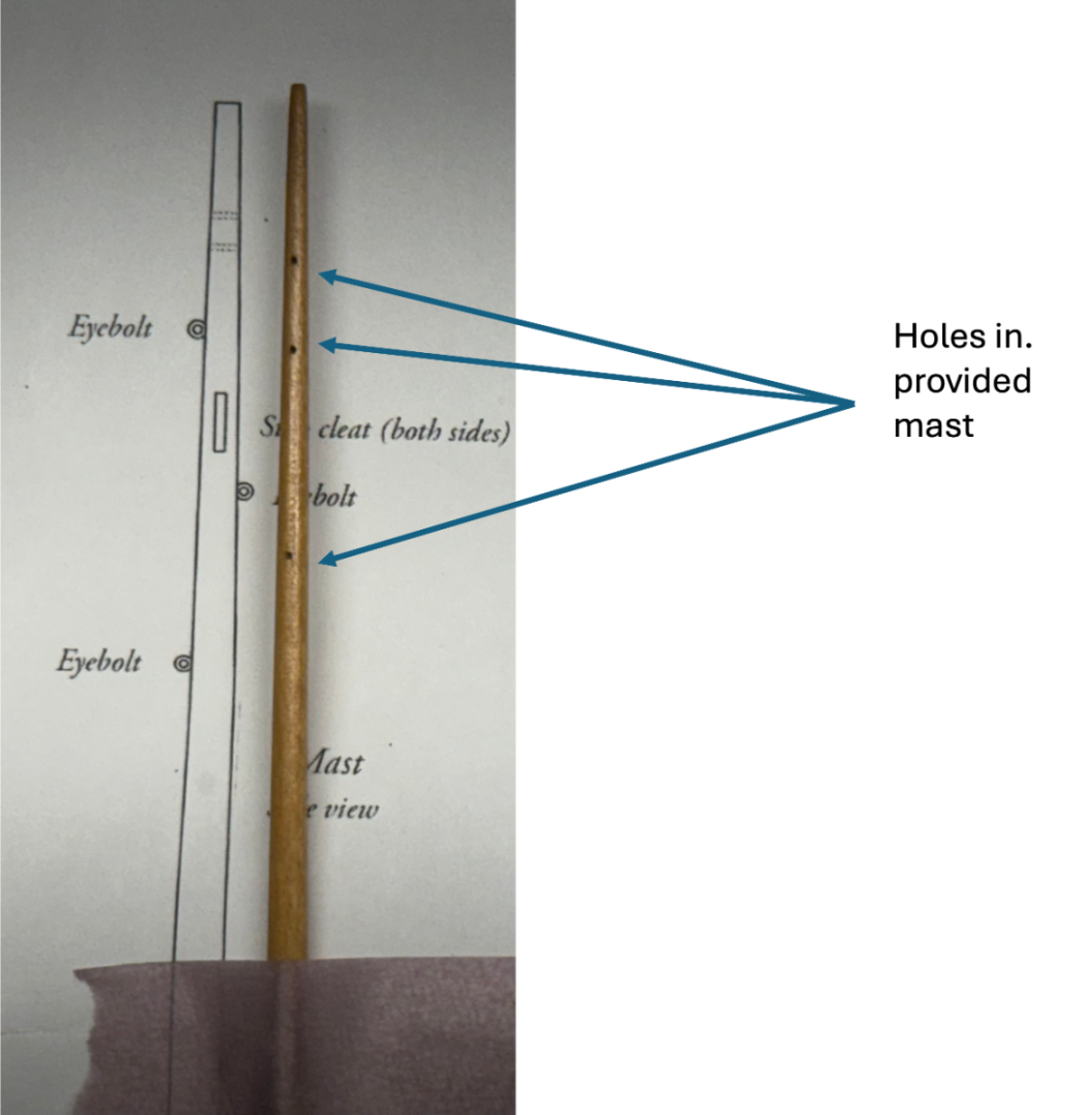
Eric, Did you notice that there was a difference in the placement of the eyebolts on the mast between the drawing and where the holes were on the provided mast? I ca't tell for sure but it appears that your mast has holes in the same places as mine (dah) so apparently those are the correct locations but i thought it worth the question.
- 62 replies
-
- 2
-
-
- Muscongus Bay Lobster Smack
- Model Shipways
- (and 1 more)
-
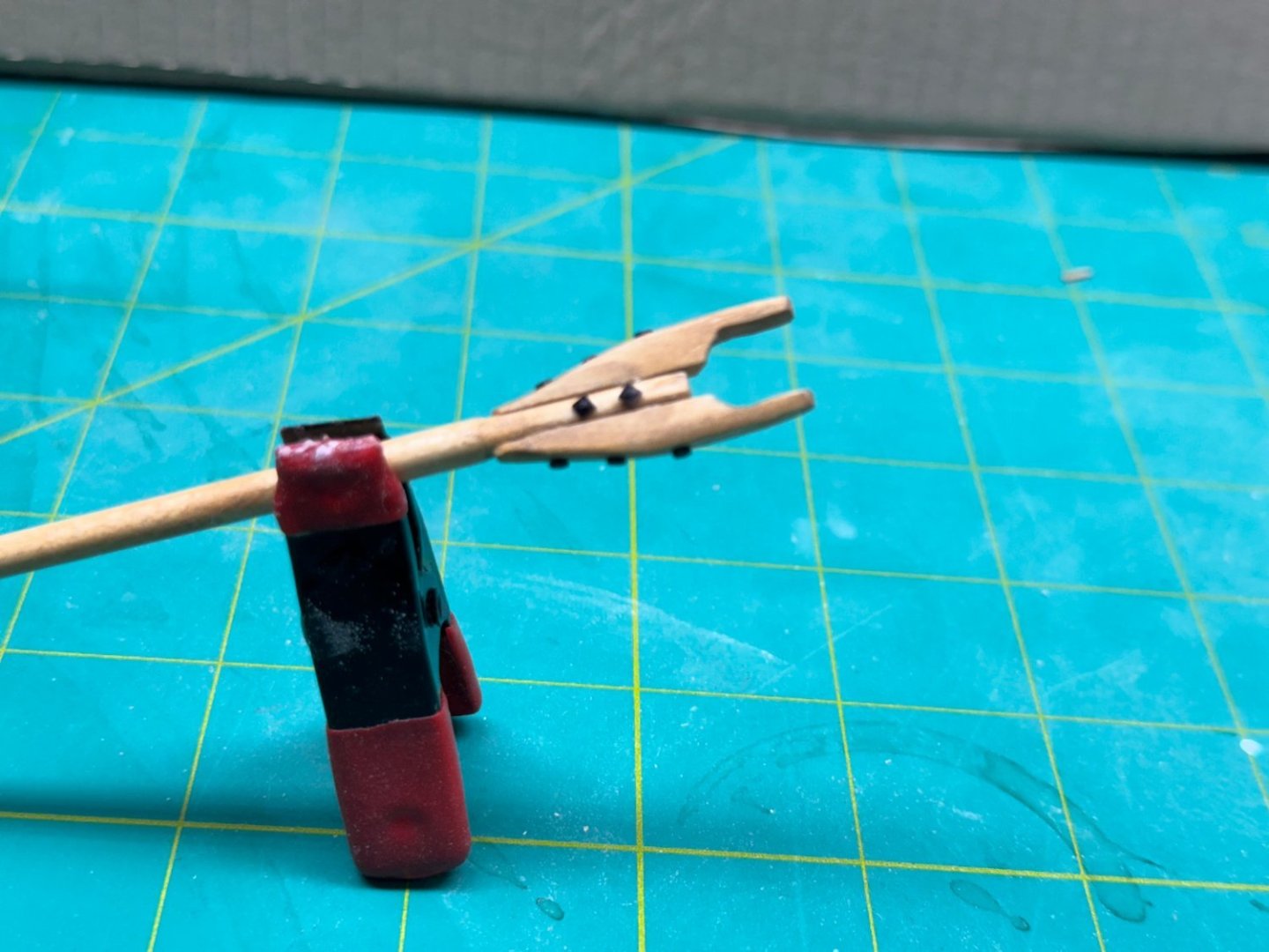
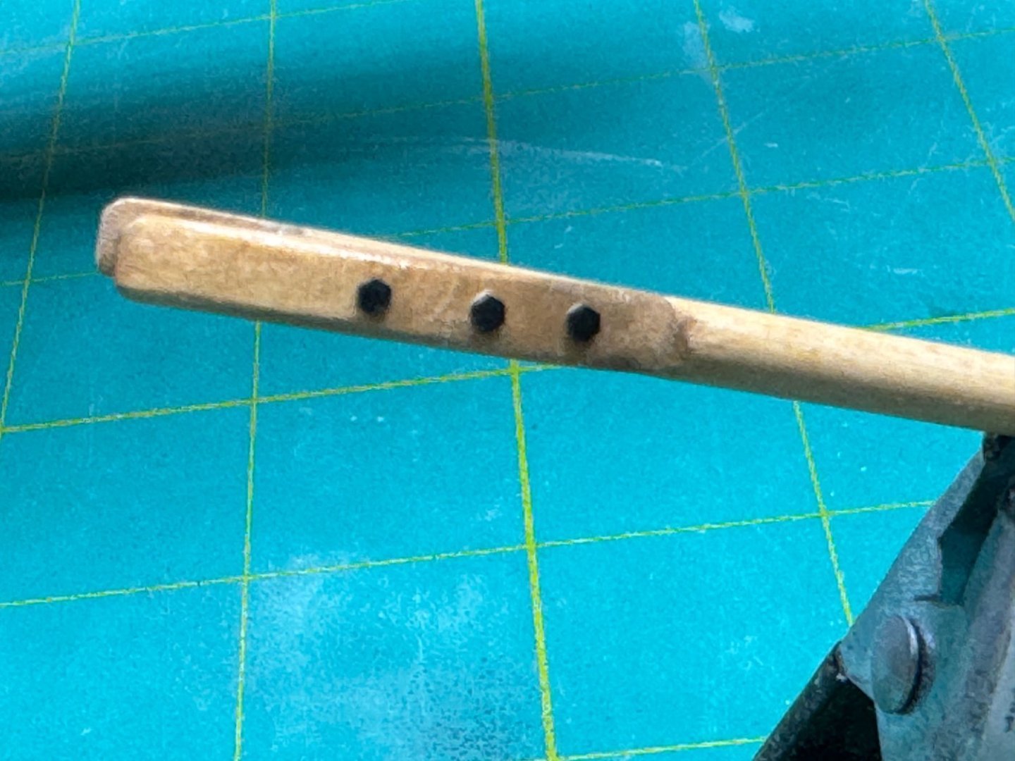
I added the eyebolts to the gaff (and bowsprit and boom - still working on the mast). I added bolt heads to the underside of the gaff since the eyebolts were very likely through-bolted due to the load they carry. Unfortunately all I had left in the parts bin were square bolts. So the gaff has hex bolts on the jaws (see post above) and square on the eyebolts. The rest of the spars will have all square bolts.
- 88 replies
-
- 2
-
-
- Muscongus Bay Lobster Smack
- Finished
- (and 1 more)
-
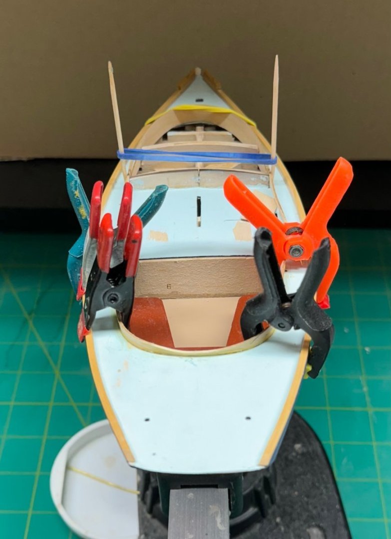
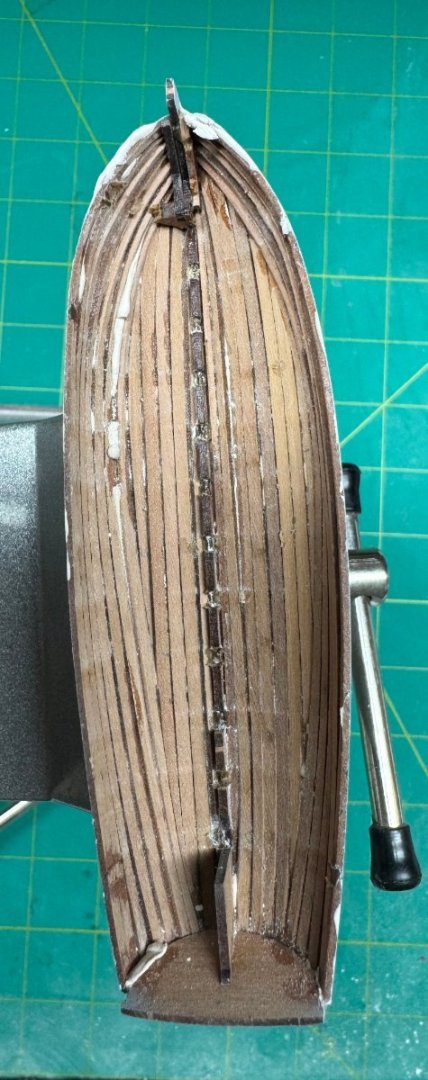
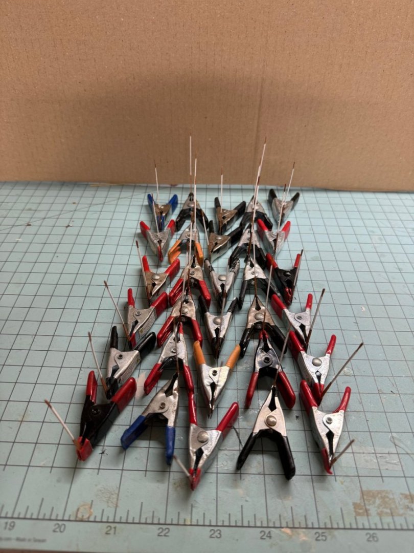
Status report: Yawl - damage to hull caused by removal of bulkheads repaired, interior sanded; needs ribs and interior paint Launch - four rows of planking completed - ,3 sheer and garboard strake - has both garboard stakes drying which accounts for all the clamps and rubber bands. Pinnance - five rows of planking completed - 3 sheer, garboard plus one (drying now). Shipyard time will be limited for next several days do to "outside" (aka girlfriend) commitments
- 422 replies
-
- 3
-
-
- Vanguard Models
- Sphinx
- (and 1 more)
-
While looking through my "parts bin" I found the bolt heads (for HO/O scale railroad engines) which appear to be the correct size for the gaff and boom jaws connections. Here's how the gaff jaws look now.
- 88 replies
-
- 5
-
-
- Muscongus Bay Lobster Smack
- Finished
- (and 1 more)
-
The transom "stopper" I employed on the yawl worked out okay so I added one to the redo of the Launch. Luckily the transom on the launch is large enough that I can put one on and not interfere with the planking.


- 422 replies
-
- 4
-
-
- Vanguard Models
- Sphinx
- (and 1 more)
-
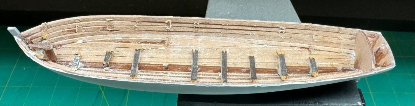
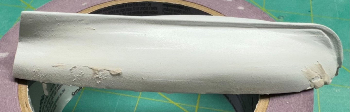
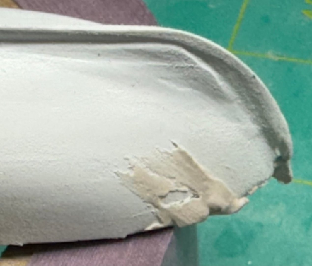
Two coats of flat white and the hull is "finished" (or so I thought). Taking the bulkheads out went well (except that in three place amidships (Bulkheads 4,5 and 6) everything came out leaving just the keel. Probably no big deal as this are is well hidden under the PE Brass floorboards. However, at the top of the planking just aft of the stem a section of planking also came out. I am not sure what happened here but clearly something was glued in a place it was n ot supposed to be. I made a fist attempt at filling in the area and proceeded to sand the interior. One point that should (IMHO) be made is that when gluing the planking together it is the planking that needs to be glued NOT the planks to the bulkheads. Although so far I have not had a problem with planks being damaged (the issue at the bow notwithstanding) I would suggest that if you are using the thinned PVA applied with a paint brush that you try and keep the glue in the area between the planks and not (as I had been doing) make sure there is glue between the bulkhead and the planks. All of the excess glue and whatever part(s) of the MDF bulkhead remains attached to the planking has to be removed or at least its removal attempted after the bulkheads are removed. Another point - once the bulkheads are removed the hull becomes quite flexible and you can split open the junction between the planks while trying to sand the interior. This happened in two places on the yawl hull. I have applied putty but I am not sure it is going to make these "go away". Maybe I can fill them with paint. I would suggest that at least one, maybe two of the bulkheads be left in place while the interior that is accessible is cleaned up and then when the last bulkheads are removed the only area that needs work is around them. The less handling of the hull after the bulkheads are removed the better.
- 422 replies
-
- 5
-
-
- Vanguard Models
- Sphinx
- (and 1 more)
-
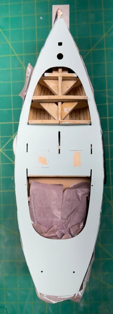
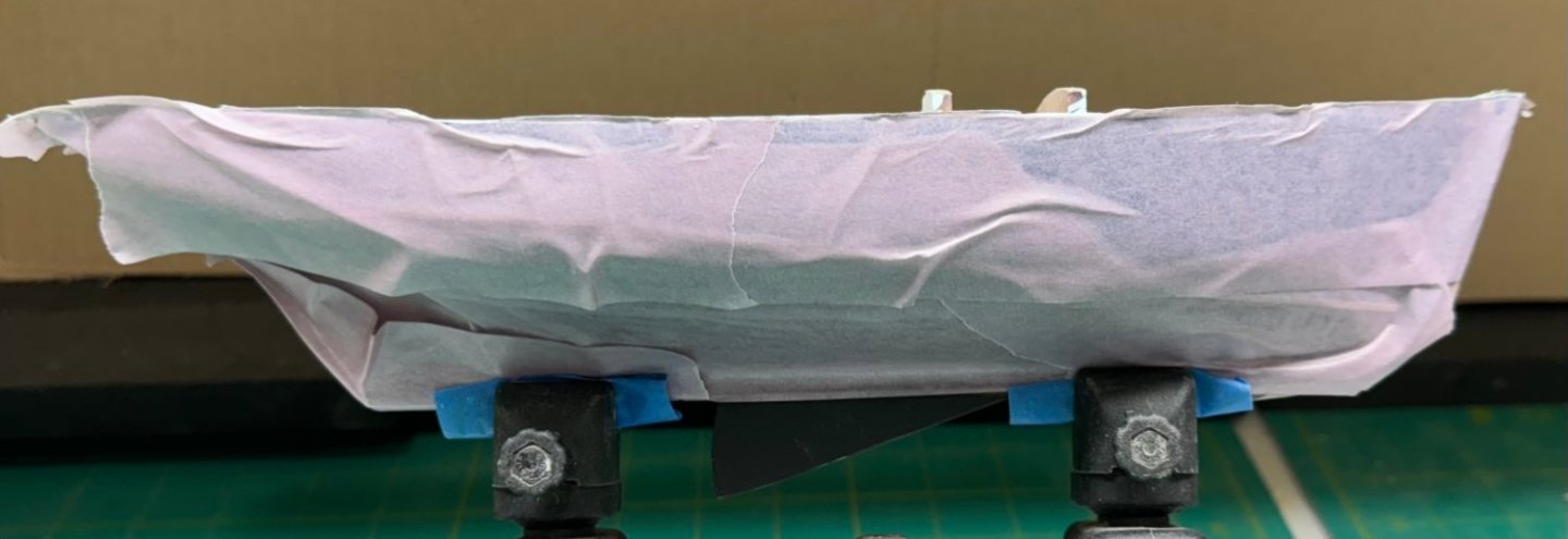
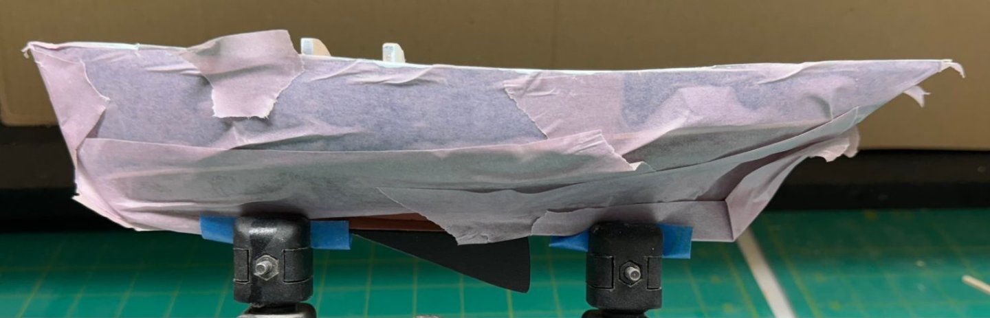
I did add a 1/16" white tape strip at the waterline except at the very most forward part at the bow. I just could not get the tape to lay flat as it went around the keel at the stem. I will deal with that "later". I removed the rudder and covered the rest of the hull in delicate surface (purple) masking tape. Not very elegant but if it projects the hull while the rest of construction proceeds it will be worth looking at this ugly picture. With the hull protected the next items are the toe rails. I want the toe rails natural and the deck painted so I better paint the deck before I try installing the toe rails. I ran a 1/16" strip of masking tape around the edge of the deck to keep free of paint an area to glue down the toe rail. I then put two coats of sanding sealer (320 sandpaper between) and then two coats of MS 4824 Clipper Blue (320 sandpaper between). I may add another coat once I get a chance to see how this looks in better (aka natural sunlight) light. I left the hatch cover area partially unpainted for the same reason I taped off the area at the deck edge.
- 88 replies
-
- 3
-
-
- Muscongus Bay Lobster Smack
- Finished
- (and 1 more)