


SJSoane
-
Posts
1,641 -
Joined
-
Last visited
Content Type
Profiles
Forums
Gallery
Events
Posts posted by SJSoane
-
-
Michael,
Very clever idea, sliding the blank progressively out of the collet chuck to keep the cutting close to the chuck. So obvious once you mention it, but not obvious enough that I ever thought of it. We continue to learn from the master!
Mark
-
-
Michael, your work continues to show the art at a level of sophistication and skill that I would not have believed possible until I see it before our very eyes...
Mark
- Omega1234 and michael mott
-
 2
2
-
-
Alan
I have been working happily at 1:64. The biggest challenge so far in terms of size was the capstans' whelps. But it is possible!
Mark
-
-
Hi Siggi,
I echo Gary's question. Do you have any photos of making the small details? They look very good.
Great photos!
Mark
-
Dear Gaetan,
Beautiful, artistic, exquisitely crafted. You are a master.
I notice your vise for holding the carving. I have seen these vises, but never how they might be used. Very ingenious.
Best wishes,
Mark
-
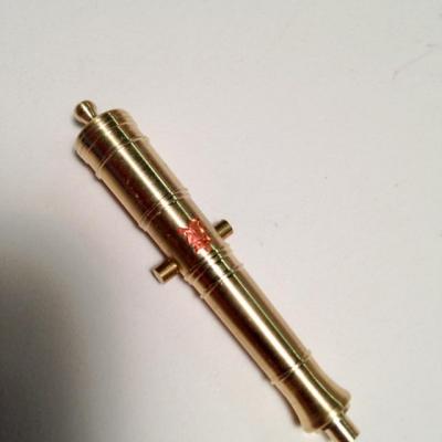
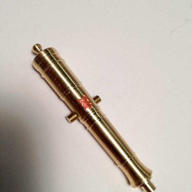
Thanks, druxey, that is a good idea. I spent the day trying fine wire, Fino modeling clay, and then some stick-on thin copper. None worked as well as the copper, which I show in a rough form here. I was thinking about casting a copy of the cannon, then adhering the thin copper to the barrel, and then engraving and cutting while it is in place. But before trying that, I will try the acrylic matt.
I am learning that, at this scale, it is an impression of detail, not as defined as I thought at first. The thin wire and modeling clay were way too "chunky" for the scale of the detail and the cannon.
druxey, any ideas on how I will transfer the pattern to the brass barrel? Of this this a case of free-handing with a fine awl?
Best wishes,
Mark
-
Thanks, Michael, this is a very good lead. I'll look up Doris' log, and track down some Fino in the morning. The etching was beginning to look like major overkill for one master....
Your machining continues to inspire me. I worked a little harder on my cannon master after seeing how you approached your project. Thanks!
Mark
-
HI everyone,
Well, I confidently started out trying to make the gun insignia with photo etch. I simplified the George III image, but when I print it out at 3/16" inch scale (about 1/8" long), even the simplified detail disappears. And I am not yet sure how much detail will even show after I sort out the etching process. Not so confident now!
Maybe there is a better idea....
Best wishes,
Mark


- aviaamator and daHeld73
-
2
-
Thanks, Sherry, for the thoughts about the resin. I'll proceed cautiously....
Best wishes,
Mark
-
Ed,
I don't know how you managed to resist the temptation to show the other hull all this time. It looks great from afar....
Mark
-
Siggi,
Phenomenal photos. It feels like we are on the actual ship.
Mark
-
-
Hi Mark,
It worked for me, drilling the hole first. I then turned it at the highest RPM on the Sherline lathe, with a very shallow cut across the area with the drilled hole. I was also using the pointed cutting bit, which presumably has a smaller surface to catch if it would. I was only aware of a smallest change in sound, but no sense of anything catching. It seemed to work without difficulty.
Best wishes,
Mark
-
Thanks, Nils, Siggi and also Ed.
Nils, I appreciate your comments, thanks.
Ed, I got an email telling me of your post, but it does not show up in my build log on my computer. Strange.... Thanks for the information about shrinkage in casting. I confess I did not even think about it when I was making the master, although I was vaguely aware of it from reading about manufacturing processes years ago. I'll see how much shrinkage will happen in 2", with lead-free pewter. I may moderate my quest for perfection, since I don't fancy right now turning another master. At 3/16" scale, a quarter or a half an inch is not really perceptible, I keep telling myself...
Siggi, thanks for the pictures of the barge. I admired that every time I visited the National Maritime Museum. I haven't been in years to Greenwich; is it still in the main building at Greenwich, or has it been moved to Chatham?
Best wishes,
Mark
-
Very nice, Siggi. What are the white objects in your moulds?
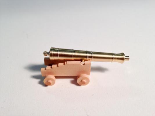
I have been thinking about painting my gun carriages red, and your photo just convinced me. They are red in most 18th century models I have seen that have guns.
Best wishes,
Mark
-
Dear Greg, druxey, Siggi, Grant and Ed,
Thank you for the kind comments. It took me almost a week of long days to produce this one master cannon, and your support on this website kept me going at times.
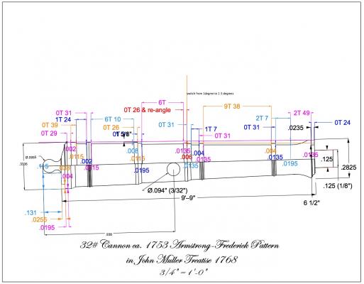
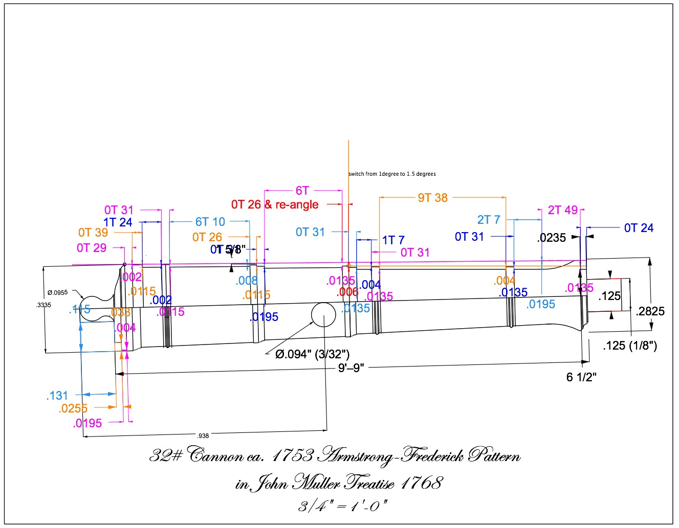
When I first laid out my "recipe" of dimensions, I did not account for the fact that the pointed cutting bit has an angled face. Cutting up to the line on the fine moldings meant that I had already cut away half of its thickness. So If you look closely at the drawing (actual sizes on the lower half, the cutting dimensions on the upper half), I thickened up the various moldings so that when I cut to the line, I ended up with the right size. But I only got to this through a number of failed trial and error recipes. I confess it got tedious! I did try switching cutting bits to a face perpendicular to the moulding on each side, but then I got so lost in where I was. I finally had to figure out how to use a pointed cutter for the entire length.
Greg, I am an admirer of your own machining skills, and I can share with you that the angle gauges did have to come into the shop only after I got very tired of setting angles by trigonometry (moving the cutter in the X dimension down a set length, then dialing in the Y direction to see if it hit the blank forming a 1 degree triangle, then adjusting and doing it again). The manual method was OK at first, but not after so many failed trial and errors. That was one of the reasons it took me so long to produce this master.
Siggi, I know how it feels to discover information after you have completed something that is now out of reach for repair. I have a few of those in my project that I keep thinking about. But I looked at your photos, and your cannon look great to me. Also, I discovered that there are a number of variations on this cannon pattern, so who will know!
Ed, I have not cast anything before, and I am going to follow the directions in David Antscherl's volume II of the Fully Framed Model. I found lead free pewter at a local jewelry supply, and will see what happens. I also just bought some Micro Mark casting resin, to see how this turns out in comparison to the pewter.
I would give a special acknowledgement to Michael Mott, whose magnificent machining precision on his skipjack engine inspired me to work a little harder at getting this as right as I could, within my own skill level.
Best wishes,
Mark
- michael mott, gjdale, daHeld73 and 1 other
-
4
-
Hi everyone,
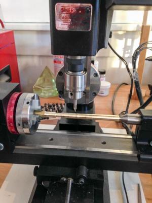
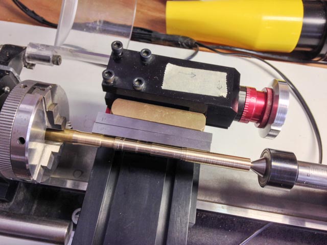
Well, after a number of rejects, I finally made a master 32 pound cannon for casting. A few details. First, I decided to use the Sherline angle cutting device for the angled cuts, since the angle to the hind of the second reinforce is different from the angle ahead of the reinforce. I used some very handy angle gauges to set the device to the 1 degree and then 1 1/2 degree parts. This was infinitely easier than calculating the tangents of the angles, and then trial and error setting the angles. The second photo shows setup using the 1 and 1/2 degree gauges.
I have a digital readout on my lathe, but this does not work on the angle device. So I had to count turns for distances. To facilitate this, I adapted an old Sherline hand wheel that can reset to 0, turning it down to fit the angle device. This helped enormously with incremental counts down the length of the cannon.
And then I drew up a recipe (fourth photo), converting actual scale lengths to numbers of full turns of the hand wheel plus numbers of increments in part of a turn. You can see this in the photo as, for example, 9T 38, which means nine full turns plus 38 increments. Each horizontal and then vertical cut is color coded the same so I could keep track of where I was.
Inspired by Michael Mott's machining, I used a center bit in the mill as seen in the first photo, for drilling the hole for the trunnion. This helped keep the hole accurately located while drilling into a curved surface (the trunnion is off center by half its diameter). It worked perfectly. Thanks, Michael!
I intend to cast these, so the muzzle mouth has a dowel on it, onto which I will attach a funnel head for making the mold.
At last, I can think about making molds!
All for now,
Mark

-
Ed,
I was taken by your comment that the clarity of the design emerged as you put it together. I think it is one of the joys of scratch building a complex design, to suddenly discover in the making of something how it was logically put together in the first place. It always gives me a deeper appreciation of our ancestors, and the deep design traditions in which they worked.
Best wishes,
Mark
- Elia, michael mott, EdT and 4 others
-
7
-
Michael, astonishing. I would not have believed it possible, and yet we saw it step by step. You are an inspiration!
You mentioned hard buttons several times for guiding your filing. How do you make those?
Best wishes,
Mark
-
Michael,
That looks like a full size lathe, making such small parts. I am impressed!
When you use a slitting saw in the lathe, which had never occurred to me as a technique--thanks for the insight!--do you shim up the stock to the center line, or it doesn't matter?
Best wishes,
Mark
-


HMS Dragon 1760 by Siggi52 - FINISHED - Scale 1:48 - English 74-Gun ship
in - Build logs for subjects built 1751 - 1800
Posted
Hi Siggi,
Yes, you are right, my mistake. The barrel is indeed 10 and 12 sided. Your method worked well!
Mark