
MORE HANDBOOKS ARE ON THEIR WAY! We will let you know when they get here.
×


wefalck
-
Posts
6,461 -
Joined
-
Last visited
Content Type
Profiles
Forums
Gallery
Events
Everything posted by wefalck
-
 I absolutely second that. I made a foray into into inserts and brazed carbide tools, but ruefully returned to my shop-ground HSS-tools, at least for brass work. There is one exception though: I love to use single-lip carbide end-mills as boring bars. These are as keen as HSS and much stiffer. When working with steel, I also like to use a very specific range of brazed carbide tools, those designed for so-called 'Swiss-lathes', these are automatic turning lathes for the mass production of small parts. They are difficult to find at a good price though. Sometimes they pop up on ebay et al. Their shaft measures only 5 mm x 5 mm and they are better ground than the brazed tools for the hobbyists. There is one notable micro-machinist and clockmaker who swears on brazed carbide tools: Jerry Kiefer (he seems to be also a promoter for Sherline ...). Perhaps he has the possibility to grind and hone them really well or access to better quality carbide.
- 128 replies
-
- 3
-

-
- zulu
- sternwheeler
- (and 1 more)
-
Personally, I like to work with steel, but having to remove large amounts of steel on small machines can be tedious. It is not so easy to get good-quality aluminium and Al leaves traces on surfaces due to its oxide layer. If I had to replicate the above tool, I probably would fabricate it from a steel disc and some bar-stock roughened out seperately. The two parts could be made to screw into each other or silvered soldered. That would be followed by the final machining. Anyway, one has to use one's imagination and/or reading books and/or (today) watching YouTube videos to get ideas. When you discover a need, you will soon discover also a solution that you can adapt to the capabilities/capacities of your machine.
-
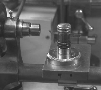
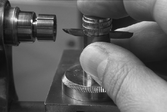
To answer the leading question: everything that is round in cross-section (and a few more things ...). Watchmakers have been using hand-gravers on metal for centuries very much like wood-turners use their chisels. This requires a certain dexterity and practice. Personally, I use it too little to have developed appropriate skills. However, the German lathe manufacturer Lorch, Schmidt & Co. (long defunct) offered a gizmo for less-skilled free-hand turners, which seems to have inspired the above modern tool: The two images are from Tony Griffith's Web-site lathe.co.uk. I gather I don't infringe any copyright here, as this is actually my own thumb on the picture 😁. A small after-market supplier, www.gg-tools.de, offered copies of this graver-holder, but I did not check, whether it is currently available. Otherwise, the beauty of a lathe (and other machine tools) is that you can use it to make more tools and gadgets. So you could make such a graver holder easily from some aluminium stock to fit the centre-height of your lathe. You would also need to attach a thick aluminium plate to the bed of the lathe. One could also add a follower nose to it and clamp a template to the base-plate. I have used this graver-holder to turn flared model parts, for instance, and made a lot of ball-handles for my machines.
-
That guide on the handle is not a bad idea - the pivot on the handle is always a weakness and wears on both, shop-made and industrial gadgets.
-
It might be easier to glue oversized roughend out parts to the boom and then shape them using the boom as a handle. Also leave the parts longer at the jaws end so that can drill a hole first where they open - in this way you can get the hole in line with the boom. Then trim to shape with files and sanding sticks, rather than a knife. Another strategy could be to take a single flat piece and cut a steep V-shaped notch to match the flattened sides of the boom. Glue in the boom and then continue as above.
-
I gather that is how 'shipbuilders' measure the length - between 'perpendiculars' ... Otherwise, one could contact the Lunenburg museum guys. I remember from my visit in 2007 that they were building dories in the workshop there.
-
Pretty neat fire-wood, I would say ...
-
Pulled the Trigger == Lathe coming
wefalck replied to kgstakes's topic in Modeling tools and Workshop Equipment
Neat self-contained unit! Just a couple of observations based on 35+ years of experience using such small lathes: - I think I would have fixed the lathe closer to the front edge, as you want to get really close to the work (wearing safety glasses !), when working on small parts. - I run all my electrical equipment off momentary foot-switches; this allows me to interrupt the current just by lifting the foot - handy during normal operation and absolutely vital in an emergency. -
For the cowls (this is what the ventilators are called) you presumably started from brass discs, I assume? Did you determine the necessary diameter by trial-and-error? One day, I have to get myself one of those dapping blocks (as jewellers call it) and matched punches ... China and India throw them onto the market at reasonable prices.
-
ANCRE.fr
-
Violin by wvdhee (Walter) - 1/1 - from scratch
wefalck replied to wvdhee's topic in Completed non-ship models
And: how does it sound ? -
There are thousands of books, photographs, prints etc. on that site - after all, it is not just a 'site', but the digital portal of the French National Library! Don't look for ship's drawings, these are either with the Service historique de la Defence (SHD) in Vincennes (late 19th century to present) or with the Musée de la Marine in Paris (everything older than late 19th century).
-
I think I would have left the exposed frames bare wood (protected with some sanding filler). Some builders put tar onto the frames for protection, but I am not sure that would have been practice at the Spanish coast. Coming on nicely ...
-
Yep, that's what I meant 👍🏻 These glow-head engines first developed in Denmark and the Netherlands for the fishing industry had to have long-strokes because the poor fuel they were designed to run on needed time to fully combust. Hence the low RPMs of around 50 to 150. They would literally run on any kind of liquid or semi-liquid hydrocarbons, such as rancid butter or seal-oil, though soot was a problem. One needed to start up the engine on something more flammable, such as alcohol or petroleum and then switch to the main fuel. The boats had two tanks for that purpose and sometime an additional tank on top of the engine to make semi-liquid fuels more liquid.
-
It appears that the pump was driven from the lay-shaft in the foreground of the lower picture. This has chain-wheel for an ordinary chain just inside the spill-head. This chain presumably led to the frame just port of the pumps, where there was a similar chain-wheel on a shaft that seems to drive an excenter, which in turn seems to have driven the balancier of the pumps. However, that balancier and the piston-rods for the pumps are missing. It is not very clear, but I think the cargo winch in front of the pumps was not driven from the lay-shaft, but traditionally via hand-cranks (missing). As I suggested in an earlier post, there was a sliding pinion that engaged the large wheel. In this way you had a two-speed winch: the upper spill-heads are driven directly from the cranks, while the lower spill-heads were driven through the gear-train, resulting in a mechanical advantage. There are two ratchet-wheels on the whinch, one oriented clockwise and the other anti-clockwise, so that one could use the winch in both directions. This kind of winch was universal on small cargo-vessels from the early decades of the 19th century on.
-
Well, the awns are there to grip animal furs or bird feather to help the seeds spreading ... I think some plumber's hemp, brushed straight, might be a more promishing option. I suppose you would get this in a DIY store (at least over here in Europe this is not a problem). The ridges of thatched roofs are their weak points and special techniques were develped in different cultures to overcome this. In some place pieces of turf were arranged along the ridges, fastened with wooden spikes, and grass and moss encouraged to grow there; in other places they used wooden boards, tiles, or in later years sheet-metal. On a boat, I could imagine that a piece of sail-cloth or similar could have been tied over the ridge. It would add to its improvised look 😉
-
Inexpensive Mill and Lathe
wefalck replied to JohnU's topic in Modeling tools and Workshop Equipment
Replacing some dodgy materials, such as plastic gib-strips can take you a long way indeed. And proper adjusting ... I went down a different route many years ago, but always found these modular system an interesting proposition, though 'combination' machines are not terribly useful, if you have the space and the money for a separate lathe and mill - very often you need to transfer parts from one or the other. However, you can create set-ups for specific machining operations that may not be possible or convenient with a standard lathe or mill. There are way of compensating back-lash, such as split leadscrew-nuts. The good thing is that once you have the machines, they can also make parts to improve themselves. The Austrian company behind these machines went through a lot of changes over the past few decades. Originally, they made the Unimat lathes. At a time they made the Unimat 4, they started to develop this modular lathe, which originally was called Unimat 1, but then changed the name to CoolTool, presumably to avoid confusion with the 'real' Unimat. The same company also served as an importer for Sherline machines and I think they were also branded CoolTool, at least for some time. Some 20 years ago I had conversations with them to buy some Sherline parts, but they had a quite high mark-up compared to buying directly in the USA. I think the trade law says, when something is assembled in country X, it become 'Made in X'. So legally it would be correct to claim 'Made in Austria', although the parts came from China. It's the assembler, who determines what quality is required from the supplier of parts and that is the key point.- 1 reply
-
- 1
-
-
On the 'attaching' itself, you would need to specify the period you are looking at, as the method and fittings for 'bending' sails developed quite a bit over the centuries ... it can also depend on the region for vernacular craft. Otherwise, yes, it is probably best to attach the sails to their respective yards, gaffs, booms etc. before these go onto the model.
-
It’s kind of a vane pump, a single vane with two valve-flaps. It’s fed through a suction hose (kept open by a metal spiral). There is a suction cage at the end, as would be used e.g. by the fire-brigade.
-
I just had a quick look at my pictures of GJØA in the museum, but today this winch is not present on her. However, normally there would be a pinion that engages with the large cog-wheel in order to effect a reduction and mechanical advantage. This may engage via a dog-clutch.
-
It is indeed vital to supply the engine with 'dry' steam, which is one of the reasons why I raised the issue of insulation in that earlier post. It would be possible to insert a water trap into the steam line, so that any condensation would be collected there, rather than entering the cylinders, and drained by the engineer from time to time. The problem of condensation is particularly important when starting up the engine from cold. Condensation is inevitable in the cylinders, which is why they are supplied with drain-cocks at both ends (for double-acting cylinders). Not sure, how they would be operated on the steam-boats, on locomotives, traction engines and the likes, there was a system of connecting rods leading to the driver's stand. Once up and running, condensation is probably less of a problem, unless it is really cold outside or the boat is moving only slowly.
-
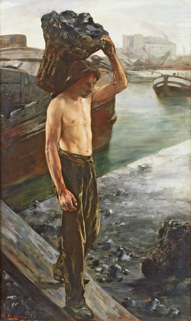
I gather there are textbook data for coal consumption per fire-grate area or amount of steam generated per hour. This machinery probably was not terribly efficient energetically, low-pressure boiler, long-stroke/low-rev engines, heat losses in the pipe-work, etc. Depends also on the calorific value, i.e. quality of the coal. I would gather that she would need several tons of coal per day. I think each sack would have weighed 80 to 100 pounds - tough guys the coal-carriers those days. I remember them carrying such sacks on their back, when we still had coal delivered to our house. Source: https://www.meisterdrucke.uk/fine-art-prints/Henri-Gervex/41701/The-Coal-Carrier,-1882-.html
- 393 replies
-
- 10
-
-
Over here in Europe at least, coal was traditionally delivered either in large wicker-baskets or in jute-sacks. Perhaps it would have been the easiest to just keep the baskets standing on deck? Unlike in seagoing ships, there probably wasn't much rocking and rolling on the river, so no worries that the fuel might go overboard.

