


wefalck
-
Posts
5,547 -
Joined
-
Last visited
Content Type
Profiles
Forums
Gallery
Events
Everything posted by wefalck
-
 I haven't build anything with decals since about 1980*, I think. Decal technology must have advanced considerably since then. If I understand the process correctly, then you can apply the 'softener' to already set decals in order to coerce them around obstacles? I am asking this question, because I just had the idea of laser-printing flags onto decal-sheet and then apply the decals on both sides to a piece of aluminium foil cut to the right size. With this softening and drying technique, the aluminium foil with the decals on could be 'draped' realistically. Does this sound feasible? *apart from the white boot-topping above the waterline that I put onto my current project, for which I used thin strips of white decal-sheet.
 -
Thanks, gentlemen. I have not intention to leave this World in the next few months, so this is not going to be a 'project for life' 😉.
-
Thanks, in the meantime, when I did some searches on Fowler B6 it popped up there ... 100 € for a kit is quite a steep price actually (for me, as I am not used to buy kits, but only tools and books). How long is the model by the way ? I didn't look up the measures of the original.
-
OK, we are in serious thread-drift now ... the phenomenon we are discussing is called 'planned obsolescence'. It's something industry has been using for decades to keep up their sales. Perfectly useable hardware is made unserviceable by designing electronic components too flimsy so that they fail prematurely, well before the actual hardware is worn out. Or making software on purpose not backward compatible anymore, claiming that otherwise performance cannot be improved (even if objectively no improvement may be needed). The component concerned are often trivial, such as capacitors, but one has to replace the whole electronics and replacements are either not sold or made uneconomically expensive. In fact, the European Commission has been working for some years now on legislation to curb such practices, because they are wasteful of mineral resources and energy. I gather, as long as our economic philosophy is built on 'growth', it is difficult to combat such practices. Another dimension of the problem is, that industry faced with this 'threat' is switching to renting out 'services', rather than selling goods. To some degree this is also supported by environmentalists, as they claim that there is too much 'unused stock' in our society. Gone are the days (well into the 1990s) that Apple prided themselves that all their operating systems were backward compatible with existing software (their own). You could run ten-year old versions of wordprocessors on the latest version of the operating system. But even back in the 1990s already there were complaints that 'productivity' software had too many bells and whistles that very few people actually use in practice. Perhaps I am not such a sophisticated user, but there are very few functions that I constantly use in my wordprocessor, spreadsheet or drawing programs that were not available already 30 years ago ...
-
P.S. Where did you get the kit from? I could not find a source on the Internet ... BTW, this is a comprehensive history of the John Fowler works: LANE, M.R. (1980): The Story of the Steam Plough Works. Fowlers of Leeds.- 410 p., London (Northgate Publishing Co. Ltd.).
-
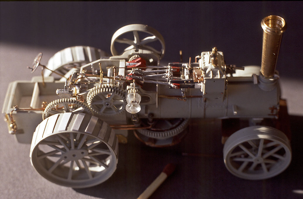
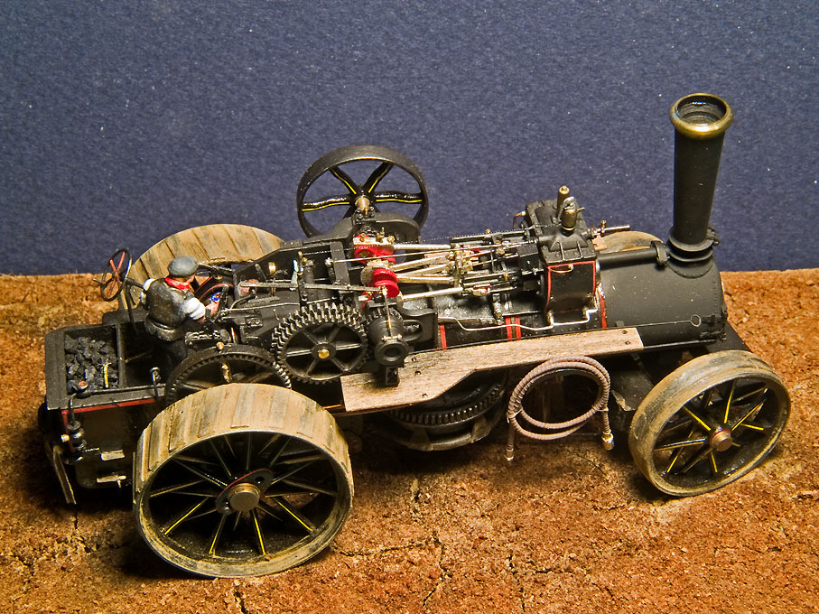
I am a great fan of Fowler traction engines, because of their looks and perhaps also because of their German connection: a young German engineer in search for better opportunities than on the continent ended up with Fowler in the 1860s. He made some important inventions/improvements to their ploughing engines, reorganised the Egyptian cotton industry with the help of Fowler engines and eventually became their agent for the German states and Eastern Europe with a seat in Magdeburg. Some 35 years ago, I built a Fowler Z7-type ploughing engine from a 1:76 Keil-Kraft kit (which at that time were readily available in model shops) with a lot of 'scratch'-building, as I had just acquired a watchmakers' lathe. The actual engine was virtually absent from the kit and various other aspects of the kit had to be corrected: Before painting showing the amount of detail added to the Keil-Kraft kit. Finished and painted Fowler class Z7 ploughing engine in 1:76 scale. I was lucky to live in the UK at the time, so I could visit various steam-fairs to take pictures of originals and there was also a local museum that owned a class BB ploughing engine. I didn't know that there was an 1:35 scale kit of a class B6 traction engine. I always wanted to build a model of those. The kit looks good, but it is a pity that the whole engine-block has been cast in one piece. I would want to make the metal parts from real metal ... does the kit come also with wheels with rubber tyres? This is the configuration as agricultural engine. Not sure what the army would have used. The agricultural wheels would give more traction 'off-road', but are rather uncomfortable to ride on paved roads. Incidentally, the German army experimented with traction engines as artillery tractors in the 1870/71 Franco-German War. I believe they were Fowler engines. There are not many accounts of their performance in the published literature - military writers of the time mostly were no techno-freaks and quite conservative. While their pulling capacity was judged favourably, the logistics of supplying them with fuel and water became too difficult as they moved away from railway lines. One should read up how the British did this during the Boer Wars, where armoured traction engines were used. Looking forward to the progress in this building log 😃
- 26 replies
-
- 13
-

-

-
Sounds (almost) familiar. My iPod is of 2006 or thereabouts. It was jumping tracks (I thought). So when I (unfortunately) dropped my trusted iPhone SE onto a tiled floor and the screen cracked, I decided to get an iPhone 14 pro - because of the telephoto lens and got one with 256 GB. With the old SE I had the same problem, that there was not enough memory to update the OS - but you can hook it up to the MacBook as virtual memory to go around the problem. Anyway, I managed to push across all the music including most of my CDs onto the iPhone 14, so that I now don't need to carry two devices. The same CDs still jump tracks, but this must be a problem when uploading them into iTunes. So it wasn't a problem with the hardrive of the iPod. Must do this again ... My wife tells me that I am IT-challenged, but I am simply not running after the latest things, if there is no need. Well, things have changed a bit since the days, when I did (scientific) coding on VAXes and the likes ..., but coding is still the basics.
-
The rails would need to be tied down to sleepers or something. Railway wheels are designed to exert some outward force onto the rails, this is what keeps them 'on track'. However, the covering looks as I would have imagined it. So one wouldn't see the sleepers anyway - hence you don't need to model them.
-
I am not sure that I understand you correctly re. the planking. I assumed that the planking serves to fill the space between the rails and around them in order to obtain a flat surface without obstacles - as you would when paving around rails. I gather you would need sleepers or other structural elements to keep the rails together. They could be, of course, part of the wooden landing stage. BTW, this growth on the piles looks good, but it wouldn't be barnacles, but rather mussels. Barnacles are only around 1/2" in diameter and sit flat on solid surfaces.
-
I am not a railway buff, however the inner planking should go up to roughly the blue line, because there needs to be clearance for the wheel-flanges - that is, when the rail does not protrude above the level of the planking. BTW, the link to the pictures doesn't seem to be working or is missing. I had to manually plug the URL into the browser.
-
The axle goes through from side to side and should be flush with them. I am not sure when this was instroduced, but sometime during the 19th century the bearing area was reinforced by diamond-shaped brass plaques that were recessed into the side (cheeks) of the blocks. If the blocks were externally strapped with iron bands, these bands became the bearing surfaces. Around the middle of the 19th century internally strapped blocks were introduced, where the wood just became a shell to prevent the metal from chafing rigging and sails. Internally strapped blocks have a higher load-bearing capacity than externally strapped ones, because the axles are supported right next to the sheaves. In the course of the 19th century it also became less common for blocks to be made from single chunks of wood, but were built up from layers that were rivetted together using metal rivets. This made their mass production simpler, because no specialised machinery was needed. In 1802 the RN had adopted the complex block-making machinery invented by Brunel (https://en.wikipedia.org/wiki/Portsmouth_Block_Mills). Some of the machines are preserved in the NMM and the Science Museum in London. They are the first examples of curve-controlled production machinery.
-
You are on the right road 👍🏻
-
Thanks for taking up my challenge 😄 OK, for the time being 2 mm seems to be the limit. One has to accept that. Printer technology evolves fast ... I don't know what modelling software you used for the blocks and what it's limitations might be, but I am wondering, why you made the slots in the block square? Normally the ends are rounded. If you can model that, it should give you also more clearance for the hole. If you can also model the the groove in the sheave, this should give you extra clearance without making the slot wider. I think building up a library of blocks might be a good idea and a nice service to the community 👍🏻
-
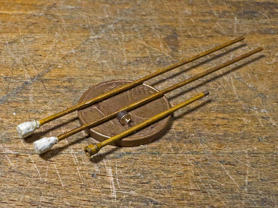
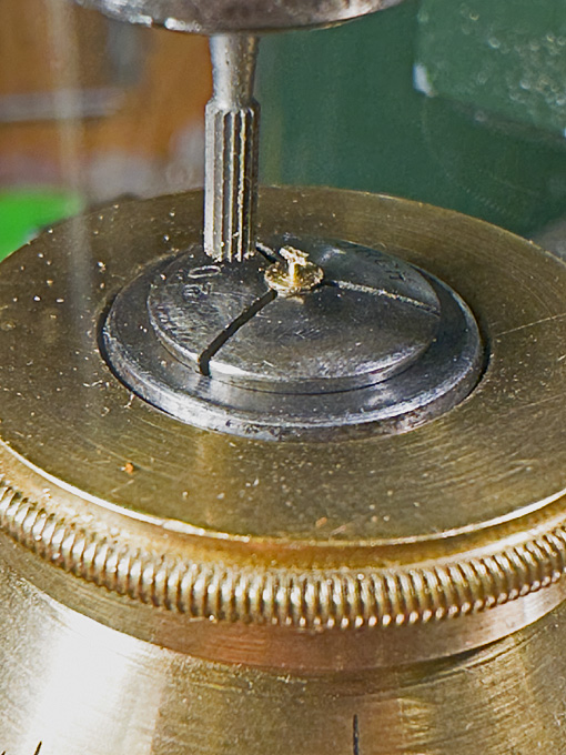
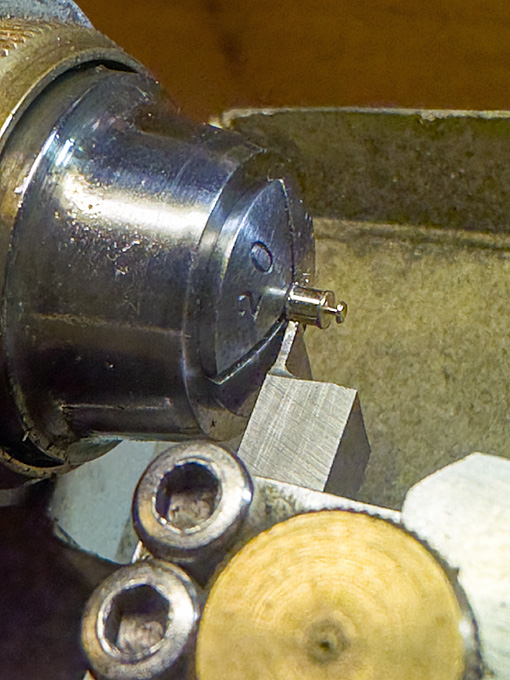
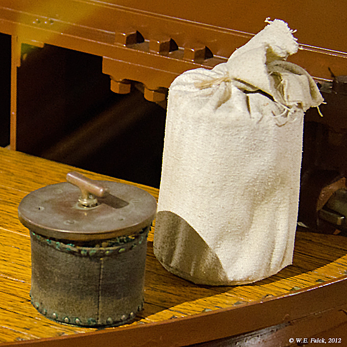
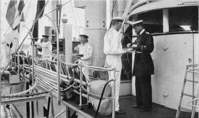
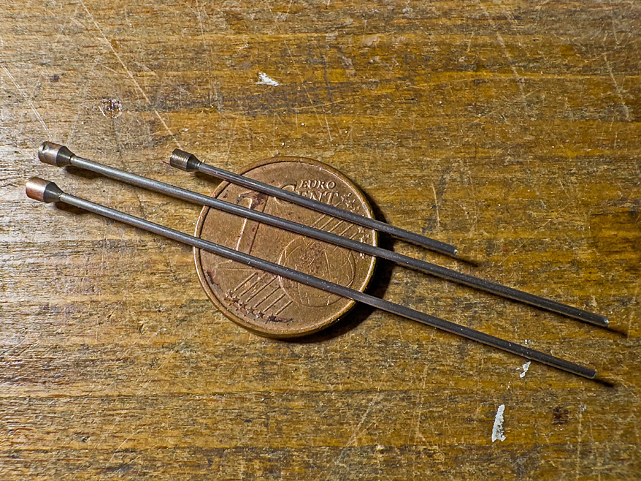
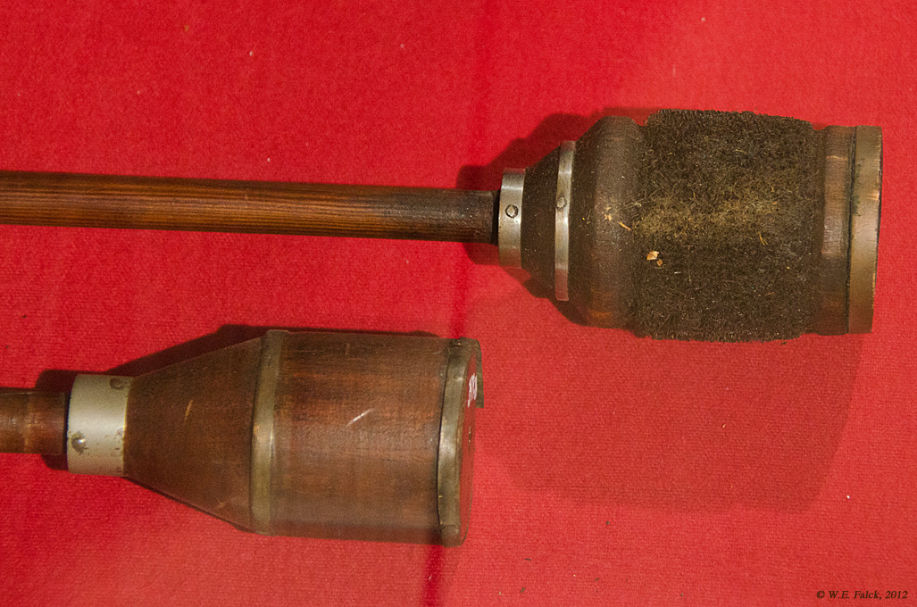
Thanks once more gentlemen for your encouraging praise! ************************************************************ Toolkit for the gun The operation of the gun required quite a few different tools for handling the projectiles and the powder-bags, as well as for cleaning and maintenance. There were two different wipers, one for cleaning with soap-water and the other one for greasing the bore after use. This still was the era of black powder, which means that the bore had to be cleaned frequently. Loading required a rammer to push the projectile and the powder-bags into the chamber of the gun. The rammer also served to unload the gun by pushing it through the muzzle. It had a depression in the front so that one would not push onto the fuse. The large-scale instruction model in the (former) Orlogmuseet in Copenhagen came with many of the necessary tools. Their look tallies with the description of a textbook on the Imperial German naval artillery (Galster, 1885). The length of the shaft was given as the length of the barrel plus some extra for one or two men to be able to hold onto it, while it was fully inserted. If there were not enough space for such long implements, there were also versions in two parts with a brass connecting sleeve. Wiper (top) and rammer (bottom) The body of the implements was turned from some 2 mm steel rod, as I had this to hand. The shaft is a 0.8 mm piano wire. The latter appears to be quite hefty, but seems to tally with the photographs. Wipers and rammer before painting As the gun will be shown undergoing a drill, the wipers are not needed and will be shown in their protective canvas covers, stored in the racks on deckhouse as per photograph below. Wipers in their protective canvas covers The canvas covers were simulated with some Vallejo liquid putty. According to Galster (1885) the covers were supposed to be painted black, but the above photograph indicates that they were white, which is what I opted for. The rammer body has two copper-bands to protect it, which were simulated with paint. The limited space in barbette seems to prevent the use of a full-length rammer, so I gave the end of the shaft a connecting sleeve simulated with paint. Tampion The photograph of the instruction model in Copenhagen also shows the expanding tampion that was constructed from two brass discs with some fibre material in between that was contained by a leather sleeve. An internal screw operated by a T-shaped handle squeezed the fibres between the disc and made them expand to lock into the muzzle. Expanding tampion for the 30,5 cm gun The tampion is probably going to be the very last machined part on this model. It was turned from a length of brass rod. The handle was first turned as a thin disk and then the excess material was milled away to leave the T-shaped handle standing. The greased leather sleeve has been simulated by some brown paint. Turning the tampion Milling the tampion handle The painted wipers, rammer and tampion Next on the list are the anchor-crane, the flagpole and flag and finally the gun-sights To be continued ....
- 881 replies
-
- 22
-
-
-
Beginning to take shape ... literally Yep, those heels always seem to be thicker than the rest. I once made a model with an entire backbone from brass sheet and had to solder on an extra thickness on both sides, which then was ground/filed to shape.
-
Did 18th and 19th century ships have flat weatherdecks?
wefalck replied to Rushdie's topic in Nautical/Naval History
No, they were running all the way through because they are, as I said earlier, structural parts that strengthen the hull at deck level. The scuppers are lead or copper pipes of around 2" internal diameter that lead from the corner below deck and the outboard, probably somewhere above the wale, say 1 to 1.5' below deck level. There would be different ways of simulating these scuppers: - The simples way would be to drill an appropriately sized hole, chamfer it a bit with a burr and then turn a soft pencil in the hole to simulate the lead - good for small scales. - Drill hole as before and insert a piece of cored solder wire from both ends; the core has to be bored out with an appropriately sized drill; flare out the ends. - There are small copper sleeves on the market that would be crimped over electrical wire instead of soldering; use instead of the solder wire; they can be found in electronics shops. -
Underhill states that these were (to his knowledge) used only on some four-masted barques(?) - that some 40 years after your FLYING FISH. I gather the FLYING FISH used hoops to attach the driver to the mast, so there would be no need for these kind of 'ladders' anyway. So, close both eyes and ignore.
-
The picture below is from the large-scale model of her in the Musée de la Marine in Paris, but in the old set-up, she is not currently on display. The model seems to indicate that the sheathing was Muntz-metal not copper. The paint-scheme is not naturalistic, as the armour-belt is modelled in real steel and left unpainted.
-
As these were 'innovatoins' that appeared late in the history of sailing ships, there may not have been a settled terminology. I wouldn't get worked up about terminology, the important thing is to understand how they worked.
-
Did 18th and 19th century ships have flat weatherdecks?
wefalck replied to Rushdie's topic in Nautical/Naval History
In principle yes. -
Did 18th and 19th century ships have flat weatherdecks?
wefalck replied to Rushdie's topic in Nautical/Naval History
Well, the construction of wooden ships is rather different from modern warships and again what is done on some kits is different from how things were done on a real ship. The design of the 'waterways' and related planks can be something quite complex on larger ships and something relatively simple on smaller ones. In general, it is a plank more or less twice the thickness of the deck-planks that runs inside along the frames or stanchions. It acts as longitudinal stiffener at deck-level and the corner to the lower planks provides a gutter from which scuppers, lead pipes, would lead the water outside. Much of the water on small ship might actually be shed through a gap between the lowest bulwark plank and the waterways/filler pieces (see below). Freeing ports with swinging flaps came in use only later. I have looked on the Web for an illustration that might be close to the situation of your model, but only found one with two decks, but it shows the principle: In your case there may not be the plank called 'plank-sheer' in the above drawing, but only filler pieces between the stanchions. So you would need to run that strip of wood inside the frames/stanchions and will the space between the stanchions up to the level of the waterway. Hope that is reasonably clear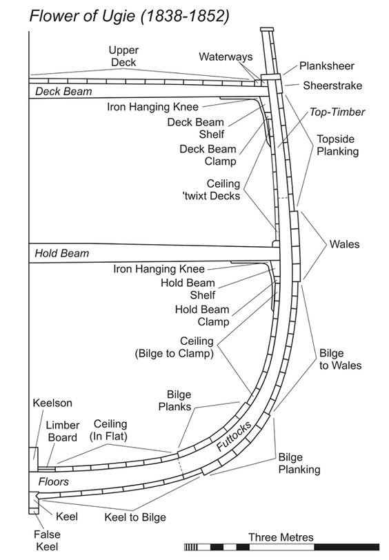
-
There are also these guys: https://www.smallstuffmodels.com/p/products.html. They make a straight Mercedes DIII in 1/72 which would be a possible candidate for marinisation.
-
In the first post FLYING FISH was mentioned. She was a three-masted ship, while Underhill mentions these vertical jack-stays some distance away from the 'jigger-mast' only for some four-masted barques(?). As the diameters of the iron masts increased it the traditional rigging of the spanker/driver with hoops became impractical and vertical jack-stays were rigged along the mast. The above jack-stays with ratlines provided access to this arrangement. As these jack-stays were only there to support men, they were probably shackled to mast-top and set taught in an eye-bolt/lug on deck either with a bottle-screw or lashings.
-
I am not into aircraft, but seeing those engine kits, I have been tempted for a long time to put one into a model of those speedboats that were popular in the 1920 and that used marinised surplus aircraft engines. Building a model of the smallest Dornier flying boats, a LIBELLE, has also been on my temptation list. They used inter alia Siemens Halske sh4 and sh5 engines as well as British radial engines.
-
Heater for sealing the end of rigging rope.
wefalck replied to DaveBaxt's topic in Modeling tools and Workshop Equipment
Could be, like the solid soldering irons that one kept on a gas-cooker or similar. However, I have been more thinking in terms of the battery-operated hand-held gadgets for sealing plastic bags. They look a bit like a stapler, you press the ends together and the heating-wires are turned on, while you move the thing along the bag. I am thinking of prongs with a flat resistance-wire (as used in styrofoam cutters) inlay. I may have some suitable flat wire that I bought for a different purpose. Could be very simple and operated from a transformer with a foot-switch, so almost no moving parts - think of a glorified clothes-peg with very narrow tips. Perhaps I shouldn't have said this, but rather ran and patented the idea ...
