


wefalck
-
Posts
5,629 -
Joined
-
Last visited
Reputation Activity
-

 wefalck got a reaction from Mfelinger in Shop-made filing-machine
Thanks !
************************
The next item to be tackled was the overarm. There are three ways in principle to guide the files or saws: 1) the file/saw is tensioned in a frame and this frame is moved up and down as can be seen in most antique machines pictured above; the advantage of a precise movement and a constant tension of the file/saw comes at the expense of a bigger moving mass so that the machine has to fixed securely to a table; if the frame is not designed in a way that it can be removed, the use of stub files and work in internal cut-outs is rather inconvenient, 2) the frame is fixed and a guiding piston moves in a sliding bearing in an over-arm; the file/saw is tensioned by a coil-spring which implies that the tension changes over the movement; the advantages are that the over-arm can be easily swung out of the way, when stub files etc. are to be used, or the file/saw has to be threaded into a cut-out; also the moving masses are smaller, 3) the over-arm is actually a leaf-spring, as is the case for many older fret-saws; this design is unsuitable for a filing machine, as the movement is not precisely linear, but has a slight swing, which is actually desirable in a fret-saw. The old jig-saw used only permitted a design according to point (2).
Boring the overarm for the upright
Boring the overarm for the upper piston bearing
The overarm was fashioned from a square piece of aluminium. The holes for the self-lubricating piston-bearing and the upright were drilled and bored out to exact dimensions. In order to give it the appearance of a cast part, a relief was milled into the sides of the arm. The ends were rounded on a filing disc mounted on an arbor in the lathe (such filing discs seem to extremely rare today, but I was able to acquire one some years ago)
Shaping the overarm to give it a ‘cast’ appearance
Rounding-off the ends of the overam using a filing disc on the lathe
The arm was then slotted for the tightening bolt that allows to set the height above the table. This bolt was found in the scrap-box of old watchmakers lathe parts, but had the unusual thread of 7/32” x 24 tpi. Luckily, I had acquired some years ago a lot of odd taps that contained a matching one.
Slotting the overarm for the tightening bolt
The finished overarm (with tightening bolt in place)
To be continued ...
-
 wefalck got a reaction from avsjerome2003 in Shop-made filing-machine
Thanks !
************************
The next item to be tackled was the overarm. There are three ways in principle to guide the files or saws: 1) the file/saw is tensioned in a frame and this frame is moved up and down as can be seen in most antique machines pictured above; the advantage of a precise movement and a constant tension of the file/saw comes at the expense of a bigger moving mass so that the machine has to fixed securely to a table; if the frame is not designed in a way that it can be removed, the use of stub files and work in internal cut-outs is rather inconvenient, 2) the frame is fixed and a guiding piston moves in a sliding bearing in an over-arm; the file/saw is tensioned by a coil-spring which implies that the tension changes over the movement; the advantages are that the over-arm can be easily swung out of the way, when stub files etc. are to be used, or the file/saw has to be threaded into a cut-out; also the moving masses are smaller, 3) the over-arm is actually a leaf-spring, as is the case for many older fret-saws; this design is unsuitable for a filing machine, as the movement is not precisely linear, but has a slight swing, which is actually desirable in a fret-saw. The old jig-saw used only permitted a design according to point (2).
Boring the overarm for the upright
Boring the overarm for the upper piston bearing
The overarm was fashioned from a square piece of aluminium. The holes for the self-lubricating piston-bearing and the upright were drilled and bored out to exact dimensions. In order to give it the appearance of a cast part, a relief was milled into the sides of the arm. The ends were rounded on a filing disc mounted on an arbor in the lathe (such filing discs seem to extremely rare today, but I was able to acquire one some years ago)
Shaping the overarm to give it a ‘cast’ appearance
Rounding-off the ends of the overam using a filing disc on the lathe
The arm was then slotted for the tightening bolt that allows to set the height above the table. This bolt was found in the scrap-box of old watchmakers lathe parts, but had the unusual thread of 7/32” x 24 tpi. Luckily, I had acquired some years ago a lot of odd taps that contained a matching one.
Slotting the overarm for the tightening bolt
The finished overarm (with tightening bolt in place)
To be continued ...
-
 wefalck got a reaction from aviaamator in Shop-made filing-machine
Thanks !
************************
The next item to be tackled was the overarm. There are three ways in principle to guide the files or saws: 1) the file/saw is tensioned in a frame and this frame is moved up and down as can be seen in most antique machines pictured above; the advantage of a precise movement and a constant tension of the file/saw comes at the expense of a bigger moving mass so that the machine has to fixed securely to a table; if the frame is not designed in a way that it can be removed, the use of stub files and work in internal cut-outs is rather inconvenient, 2) the frame is fixed and a guiding piston moves in a sliding bearing in an over-arm; the file/saw is tensioned by a coil-spring which implies that the tension changes over the movement; the advantages are that the over-arm can be easily swung out of the way, when stub files etc. are to be used, or the file/saw has to be threaded into a cut-out; also the moving masses are smaller, 3) the over-arm is actually a leaf-spring, as is the case for many older fret-saws; this design is unsuitable for a filing machine, as the movement is not precisely linear, but has a slight swing, which is actually desirable in a fret-saw. The old jig-saw used only permitted a design according to point (2).
Boring the overarm for the upright
Boring the overarm for the upper piston bearing
The overarm was fashioned from a square piece of aluminium. The holes for the self-lubricating piston-bearing and the upright were drilled and bored out to exact dimensions. In order to give it the appearance of a cast part, a relief was milled into the sides of the arm. The ends were rounded on a filing disc mounted on an arbor in the lathe (such filing discs seem to extremely rare today, but I was able to acquire one some years ago)
Shaping the overarm to give it a ‘cast’ appearance
Rounding-off the ends of the overam using a filing disc on the lathe
The arm was then slotted for the tightening bolt that allows to set the height above the table. This bolt was found in the scrap-box of old watchmakers lathe parts, but had the unusual thread of 7/32” x 24 tpi. Luckily, I had acquired some years ago a lot of odd taps that contained a matching one.
Slotting the overarm for the tightening bolt
The finished overarm (with tightening bolt in place)
To be continued ...
-
 wefalck got a reaction from Mike Y in Shop-made filing-machine
Thanks !
************************
The next item to be tackled was the overarm. There are three ways in principle to guide the files or saws: 1) the file/saw is tensioned in a frame and this frame is moved up and down as can be seen in most antique machines pictured above; the advantage of a precise movement and a constant tension of the file/saw comes at the expense of a bigger moving mass so that the machine has to fixed securely to a table; if the frame is not designed in a way that it can be removed, the use of stub files and work in internal cut-outs is rather inconvenient, 2) the frame is fixed and a guiding piston moves in a sliding bearing in an over-arm; the file/saw is tensioned by a coil-spring which implies that the tension changes over the movement; the advantages are that the over-arm can be easily swung out of the way, when stub files etc. are to be used, or the file/saw has to be threaded into a cut-out; also the moving masses are smaller, 3) the over-arm is actually a leaf-spring, as is the case for many older fret-saws; this design is unsuitable for a filing machine, as the movement is not precisely linear, but has a slight swing, which is actually desirable in a fret-saw. The old jig-saw used only permitted a design according to point (2).
Boring the overarm for the upright
Boring the overarm for the upper piston bearing
The overarm was fashioned from a square piece of aluminium. The holes for the self-lubricating piston-bearing and the upright were drilled and bored out to exact dimensions. In order to give it the appearance of a cast part, a relief was milled into the sides of the arm. The ends were rounded on a filing disc mounted on an arbor in the lathe (such filing discs seem to extremely rare today, but I was able to acquire one some years ago)
Shaping the overarm to give it a ‘cast’ appearance
Rounding-off the ends of the overam using a filing disc on the lathe
The arm was then slotted for the tightening bolt that allows to set the height above the table. This bolt was found in the scrap-box of old watchmakers lathe parts, but had the unusual thread of 7/32” x 24 tpi. Luckily, I had acquired some years ago a lot of odd taps that contained a matching one.
Slotting the overarm for the tightening bolt
The finished overarm (with tightening bolt in place)
To be continued ...
-
 wefalck got a reaction from uss frolick in Mystery topsail over gaff
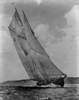
One should know the type of boat first. Square topsails rigged on a very short flying yard have been in use on commercial ships until about the last quarter of the 19th century. It then became replaced by the three-sided variant. On sport boats four-sided topsails on a longer, almost vertical yard were used into around the 1920s. So, one really needs to know the type of ship/boat in order to comment on the way of rigging.
BTW, the run of sail cloths on the mainsail is rather unusual in being horizontal. They would normally be parallel to the mast or to the after edge.
-
wefalck got a reaction from Mfelinger in Shop-made filing-machine
The machine-files come in various shapes and sizes, therefore, various holders to hold them securly and parallel to the axis of movement had to be designed. I opted for sockets into which bushings for the various file sizes will fit. Additional bushing were made to hold fine jewelers saws, so that the machine can also be used as fret-saw.
Cross-drilling the file-holder during construction
The holders to attach onto the driving piston and the guiding piston in the overam were turned from steel. The holders were tapped M3 for two set-screws on opposite sides that will act directly on the files.
Cross-drilling bushings for various files
The bushings were turned from aluminium with a selection of internal diameters to fit the available files. They were then cross-drilled to allow the set-screws in the holders to pass through. In fact, the holder on the driving piston has two sets of set-screws set 90° apart in order to allow the orientation of triangular and rectangular files as needed.
The collection of bushings
The guiding piston had a 8 mm x 1 mm thread cut on the watchmakers lathe, as I had a suitable tap for this M8 (fine) thread. Two thumb-nuts with this thread were machined from aluminium (to keep the mass of the guiding piston low). They will give a coil-spring around the piston the necessary intial tension. It is necessary to keep the very thin (1 mm diameter) files under tension in order to prevent them from buckling during the up-stroke.
Lower and upper file-holder together with guiding piston
To be continued ...
-
 wefalck got a reaction from mtaylor in Mystery topsail over gaff
One should know the type of boat first. Square topsails rigged on a very short flying yard have been in use on commercial ships until about the last quarter of the 19th century. It then became replaced by the three-sided variant. On sport boats four-sided topsails on a longer, almost vertical yard were used into around the 1920s. So, one really needs to know the type of ship/boat in order to comment on the way of rigging.
BTW, the run of sail cloths on the mainsail is rather unusual in being horizontal. They would normally be parallel to the mast or to the after edge.
-
 wefalck got a reaction from MAK41 in Mystery topsail over gaff
One should know the type of boat first. Square topsails rigged on a very short flying yard have been in use on commercial ships until about the last quarter of the 19th century. It then became replaced by the three-sided variant. On sport boats four-sided topsails on a longer, almost vertical yard were used into around the 1920s. So, one really needs to know the type of ship/boat in order to comment on the way of rigging.
BTW, the run of sail cloths on the mainsail is rather unusual in being horizontal. They would normally be parallel to the mast or to the after edge.
-
 wefalck got a reaction from Canute in Mystery topsail over gaff
One should know the type of boat first. Square topsails rigged on a very short flying yard have been in use on commercial ships until about the last quarter of the 19th century. It then became replaced by the three-sided variant. On sport boats four-sided topsails on a longer, almost vertical yard were used into around the 1920s. So, one really needs to know the type of ship/boat in order to comment on the way of rigging.
BTW, the run of sail cloths on the mainsail is rather unusual in being horizontal. They would normally be parallel to the mast or to the after edge.
-
 wefalck got a reaction from Ulises Victoria in weathering sailing ship's
You may also want to have a look her at post no. 39ff: http://modelshipworld.com/index.php/topic/68-zuiderzee-botter-by-wefalck-artitec-resin/?p=53698, leading to the final product:
-
wefalck got a reaction from Canute in Turning a Lathe into a table saw
Indeed many bench lathes, including those for modellers, such as the Unimat, had saw-tables as an option. For added precision the saw-arbors we countersunk at the end, so that they could be supported by the tailstock.
However, when sawing a lot of wood, I would be cautious with all the sawdust around that it doesn't get into the spindle bearings. Also sawdust and oil makes mixtures that stick to leadscrews and can lead to excessive wear, particular when metal chips are mixed in as well.
-
 wefalck got a reaction from Modeler12 in How to make best use of your milling machine. Tips and techniques
I like this idea of using small ball-bearings as hold-downs and may adapt it to one of my machines
-
wefalck got a reaction from avsjerome2003 in Shop-made filing-machine
The machine-files come in various shapes and sizes, therefore, various holders to hold them securly and parallel to the axis of movement had to be designed. I opted for sockets into which bushings for the various file sizes will fit. Additional bushing were made to hold fine jewelers saws, so that the machine can also be used as fret-saw.
Cross-drilling the file-holder during construction
The holders to attach onto the driving piston and the guiding piston in the overam were turned from steel. The holders were tapped M3 for two set-screws on opposite sides that will act directly on the files.
Cross-drilling bushings for various files
The bushings were turned from aluminium with a selection of internal diameters to fit the available files. They were then cross-drilled to allow the set-screws in the holders to pass through. In fact, the holder on the driving piston has two sets of set-screws set 90° apart in order to allow the orientation of triangular and rectangular files as needed.
The collection of bushings
The guiding piston had a 8 mm x 1 mm thread cut on the watchmakers lathe, as I had a suitable tap for this M8 (fine) thread. Two thumb-nuts with this thread were machined from aluminium (to keep the mass of the guiding piston low). They will give a coil-spring around the piston the necessary intial tension. It is necessary to keep the very thin (1 mm diameter) files under tension in order to prevent them from buckling during the up-stroke.
Lower and upper file-holder together with guiding piston
To be continued ...
-
 wefalck got a reaction from ianmajor in Shop-made filing-machine
The machine-files come in various shapes and sizes, therefore, various holders to hold them securly and parallel to the axis of movement had to be designed. I opted for sockets into which bushings for the various file sizes will fit. Additional bushing were made to hold fine jewelers saws, so that the machine can also be used as fret-saw.
Cross-drilling the file-holder during construction
The holders to attach onto the driving piston and the guiding piston in the overam were turned from steel. The holders were tapped M3 for two set-screws on opposite sides that will act directly on the files.
Cross-drilling bushings for various files
The bushings were turned from aluminium with a selection of internal diameters to fit the available files. They were then cross-drilled to allow the set-screws in the holders to pass through. In fact, the holder on the driving piston has two sets of set-screws set 90° apart in order to allow the orientation of triangular and rectangular files as needed.
The collection of bushings
The guiding piston had a 8 mm x 1 mm thread cut on the watchmakers lathe, as I had a suitable tap for this M8 (fine) thread. Two thumb-nuts with this thread were machined from aluminium (to keep the mass of the guiding piston low). They will give a coil-spring around the piston the necessary intial tension. It is necessary to keep the very thin (1 mm diameter) files under tension in order to prevent them from buckling during the up-stroke.
Lower and upper file-holder together with guiding piston
To be continued ...
-
wefalck got a reaction from mtaylor in Shop-made filing-machine
The machine-files come in various shapes and sizes, therefore, various holders to hold them securly and parallel to the axis of movement had to be designed. I opted for sockets into which bushings for the various file sizes will fit. Additional bushing were made to hold fine jewelers saws, so that the machine can also be used as fret-saw.
Cross-drilling the file-holder during construction
The holders to attach onto the driving piston and the guiding piston in the overam were turned from steel. The holders were tapped M3 for two set-screws on opposite sides that will act directly on the files.
Cross-drilling bushings for various files
The bushings were turned from aluminium with a selection of internal diameters to fit the available files. They were then cross-drilled to allow the set-screws in the holders to pass through. In fact, the holder on the driving piston has two sets of set-screws set 90° apart in order to allow the orientation of triangular and rectangular files as needed.
The collection of bushings
The guiding piston had a 8 mm x 1 mm thread cut on the watchmakers lathe, as I had a suitable tap for this M8 (fine) thread. Two thumb-nuts with this thread were machined from aluminium (to keep the mass of the guiding piston low). They will give a coil-spring around the piston the necessary intial tension. It is necessary to keep the very thin (1 mm diameter) files under tension in order to prevent them from buckling during the up-stroke.
Lower and upper file-holder together with guiding piston
To be continued ...
-
wefalck got a reaction from mtaylor in Turning a Lathe into a table saw
Indeed many bench lathes, including those for modellers, such as the Unimat, had saw-tables as an option. For added precision the saw-arbors we countersunk at the end, so that they could be supported by the tailstock.
However, when sawing a lot of wood, I would be cautious with all the sawdust around that it doesn't get into the spindle bearings. Also sawdust and oil makes mixtures that stick to leadscrews and can lead to excessive wear, particular when metal chips are mixed in as well.
-
wefalck got a reaction from avsjerome2003 in Shop-made filing-machine
Thank you … at my pace it will still take a while ...
*****************************
The original drive-shaft was made from a steel of rather poor machineability. It was impossible to achieve a satisfactory surface finish on it with the watchmaker's lathe. As I intended to change the original design slightly anyway, a new drive-shaft was turned from a piece of 32 mm round steel. This shaft was bored out for the 6 mm diameter gear-box output shaft to which it will be attached with a set-screw.
Original drive-shaft and crank
New drive shaft/crank, cross-head, bearing block, and piston
The whole crank mechanism was also replaced, as it was badly worn due to steel-on-steel sliding friction without any lubrication. Originally a round pin was sliding in the cross-head slot. The new design provides for more positive guidance. A proper cross-head bearing block was machined from brass and will slide in a new cross-head.
Assembled new drive shaft/crank, cross-head, bearing block, and piston
The new crank was bored for the cross-head pin at different distances from the axis, which allows to set the stroke of the machine at 10 mm, 15 mm, and 20 mm. However, it will be necessary to almost dismantle the whole driving mechanism to change the stroke, as the set-screws for the cross-head pin would not be very accessible. The maximum stroke of 20 mm may not be possible with the current file-holder design due to sufficient clearance under the table, when it is inclined. Practical experience will show, whether a 15 mm stroke is satisfactory.
New drive mechanism (provisionally) in place
To be continued ...
-
wefalck got a reaction from avsjerome2003 in Shop-made filing-machine
I gather, a real mechanic would throw up his hands into the air, if he sees me working ….
**************************
The next part to be tackled was the socket for the overam holder. An overam is needed for guiding the delicate machine files and for taking up the side pressure when filing. The foot for the sawing table on the casting was hollow and sort of house-shaped inside. A piece of aluminium bar was carefully milled to shape and size to provide a snug fit. Two tapped holes will locate it in place.
Shop-made boring bar with collet to fit the milling machine
Boring-out the hole for the overam upright
Drilling the 10 mm hole for upright round bar proved to be taxing for the capacity of my machines. There was not enough clearance under the mill for such large-size drill. Due to the hole being in one end of the part, it would also not fit into the four-jaw chuck for boring out. In the end, I realised a long-planned project and made an adjustable boring bar from a piece of 8 mm rod. For this I also had to fashion a collet with three set-screws for 8 mm bars etc. With this boring bar it was easy to drill out the hole with an excellent surface finish.
Overam holding socket
Overamr holding sockt in place
To be continued ...
-
 wefalck got a reaction from dgbot in Shop-made filing-machine
Thank you … at my pace it will still take a while ...
*****************************
The original drive-shaft was made from a steel of rather poor machineability. It was impossible to achieve a satisfactory surface finish on it with the watchmaker's lathe. As I intended to change the original design slightly anyway, a new drive-shaft was turned from a piece of 32 mm round steel. This shaft was bored out for the 6 mm diameter gear-box output shaft to which it will be attached with a set-screw.
Original drive-shaft and crank
New drive shaft/crank, cross-head, bearing block, and piston
The whole crank mechanism was also replaced, as it was badly worn due to steel-on-steel sliding friction without any lubrication. Originally a round pin was sliding in the cross-head slot. The new design provides for more positive guidance. A proper cross-head bearing block was machined from brass and will slide in a new cross-head.
Assembled new drive shaft/crank, cross-head, bearing block, and piston
The new crank was bored for the cross-head pin at different distances from the axis, which allows to set the stroke of the machine at 10 mm, 15 mm, and 20 mm. However, it will be necessary to almost dismantle the whole driving mechanism to change the stroke, as the set-screws for the cross-head pin would not be very accessible. The maximum stroke of 20 mm may not be possible with the current file-holder design due to sufficient clearance under the table, when it is inclined. Practical experience will show, whether a 15 mm stroke is satisfactory.
New drive mechanism (provisionally) in place
To be continued ...
-
 wefalck got a reaction from cristikc in Shop-made filing-machine
Thank you … at my pace it will still take a while ...
*****************************
The original drive-shaft was made from a steel of rather poor machineability. It was impossible to achieve a satisfactory surface finish on it with the watchmaker's lathe. As I intended to change the original design slightly anyway, a new drive-shaft was turned from a piece of 32 mm round steel. This shaft was bored out for the 6 mm diameter gear-box output shaft to which it will be attached with a set-screw.
Original drive-shaft and crank
New drive shaft/crank, cross-head, bearing block, and piston
The whole crank mechanism was also replaced, as it was badly worn due to steel-on-steel sliding friction without any lubrication. Originally a round pin was sliding in the cross-head slot. The new design provides for more positive guidance. A proper cross-head bearing block was machined from brass and will slide in a new cross-head.
Assembled new drive shaft/crank, cross-head, bearing block, and piston
The new crank was bored for the cross-head pin at different distances from the axis, which allows to set the stroke of the machine at 10 mm, 15 mm, and 20 mm. However, it will be necessary to almost dismantle the whole driving mechanism to change the stroke, as the set-screws for the cross-head pin would not be very accessible. The maximum stroke of 20 mm may not be possible with the current file-holder design due to sufficient clearance under the table, when it is inclined. Practical experience will show, whether a 15 mm stroke is satisfactory.
New drive mechanism (provisionally) in place
To be continued ...
-
wefalck got a reaction from Mfelinger in Shop-made filing-machine
Good point, thibaultron, about the hand-files that are cut for the push stroke, while machine files have a socket at both ends, but normally are inserted in such way, that they cut on the down-stroke of the machine. I also acquired a couple of diamond-studded stub-files with prismatic resp. cylindrical cross-section for use in filing machines; the obviously cut in both directions.
*****************
The lathe-turned part for the bearing-barrel was sawn in half and the two halfs were clamped end on in the vice after careful alignment. With a fly-cutter the surface was milled perfectly flat and the diameter reduced to bring the rotational axis of the table into its surface.
Milling flat the halves of the bearing-barrel
The position for the barrel was marked out on the piece of 4 mm aluminium that will become the table. In the following step the positions for the mounting screws were marked out and drilled mit a 3 mm drill on the drill press. The two half-barrels then were stuck onto the table with a few drops of cyanoacrylate glue after careful alignment.
Bearing-barrel in position on the underside of the filing-table
The positions for the mounting screws then were marked with a transfer-punch. A light knock separated the parts again, which were then transfered to the mill for drilling and tapping M3 of the mounting holes. I usually start the tap on the mill with a few turns to ensure it is perfectly concentric to the hole and vertical. The tapping is completed by hand.
Drilling and tapping the mounting holes for the table on the bearing-barrel
Sqaring the edges of the aluminium plate for the filing-table proved to be just at the edge of the capacity of the milling machine. The plate was clamped to the vice on the mill with a C-clamp and the edges milled flat.
Squaring the edges of the filing-table
With the bearing-barrel screwed onto the underside of the table, the assembly was bolted to the table of the milling machine for milling the slot for the holding-down bolt. This holding down-bolt will be tightened using a excentric lever.
Milling the slot for the holding-down bolt
To be continued ...
-
 wefalck got a reaction from gjdale in Shop-made filing-machine
Thank you … at my pace it will still take a while ...
*****************************
The original drive-shaft was made from a steel of rather poor machineability. It was impossible to achieve a satisfactory surface finish on it with the watchmaker's lathe. As I intended to change the original design slightly anyway, a new drive-shaft was turned from a piece of 32 mm round steel. This shaft was bored out for the 6 mm diameter gear-box output shaft to which it will be attached with a set-screw.
Original drive-shaft and crank
New drive shaft/crank, cross-head, bearing block, and piston
The whole crank mechanism was also replaced, as it was badly worn due to steel-on-steel sliding friction without any lubrication. Originally a round pin was sliding in the cross-head slot. The new design provides for more positive guidance. A proper cross-head bearing block was machined from brass and will slide in a new cross-head.
Assembled new drive shaft/crank, cross-head, bearing block, and piston
The new crank was bored for the cross-head pin at different distances from the axis, which allows to set the stroke of the machine at 10 mm, 15 mm, and 20 mm. However, it will be necessary to almost dismantle the whole driving mechanism to change the stroke, as the set-screws for the cross-head pin would not be very accessible. The maximum stroke of 20 mm may not be possible with the current file-holder design due to sufficient clearance under the table, when it is inclined. Practical experience will show, whether a 15 mm stroke is satisfactory.
New drive mechanism (provisionally) in place
To be continued ...
-
wefalck got a reaction from avsjerome2003 in Shop-made filing-machine
Well, too much travelling the last few weeks resulted in little progress. It is frightening to think I started this project already in March, thinking that I would quickly return to my WESPE-class gun-boat project …
******
The excentric rod was turned from a piece of steel, while the actual lever with the ball end is a recovered piece from a similar broken commercial product. For other pieces of equipment I turned such levers myself using a ball-turning attachment.
Method for turning the excentric for the holding-down bolt
Holding- down bolt and excentric lever assembly
Table bearing barrel and locking arrangement
To be continued ...
-
 wefalck got a reaction from hornet in Shop-made filing-machine
Thank you … at my pace it will still take a while ...
*****************************
The original drive-shaft was made from a steel of rather poor machineability. It was impossible to achieve a satisfactory surface finish on it with the watchmaker's lathe. As I intended to change the original design slightly anyway, a new drive-shaft was turned from a piece of 32 mm round steel. This shaft was bored out for the 6 mm diameter gear-box output shaft to which it will be attached with a set-screw.
Original drive-shaft and crank
New drive shaft/crank, cross-head, bearing block, and piston
The whole crank mechanism was also replaced, as it was badly worn due to steel-on-steel sliding friction without any lubrication. Originally a round pin was sliding in the cross-head slot. The new design provides for more positive guidance. A proper cross-head bearing block was machined from brass and will slide in a new cross-head.
Assembled new drive shaft/crank, cross-head, bearing block, and piston
The new crank was bored for the cross-head pin at different distances from the axis, which allows to set the stroke of the machine at 10 mm, 15 mm, and 20 mm. However, it will be necessary to almost dismantle the whole driving mechanism to change the stroke, as the set-screws for the cross-head pin would not be very accessible. The maximum stroke of 20 mm may not be possible with the current file-holder design due to sufficient clearance under the table, when it is inclined. Practical experience will show, whether a 15 mm stroke is satisfactory.
New drive mechanism (provisionally) in place
To be continued ...
-
wefalck got a reaction from avsjerome2003 in Shop-made filing-machine
As can be seen on the photograph showing the disassembled jigsaw, the piston for the saw-blade was guided by two self-aligning bearings. These bearings essentially were two cast-iron spheres set into slots and that were bored for the steel piston of 9.5 mm diameter (3/8”).
Self-aligning bearings in the original jig-saw
Lubrication relied on the self-lubrication of the graphite in the cast iron and the system had already considerable play in consequence. Therefore, the spheres were bored out to accept 10 mm self-lubricating bushings for 8 mm rods. These came from China through a well-known Internet service and are presumably normally used in computer printers and the like. Self-lubriacting bushings were chosen, because oiling would have been difficult under operating conditions. The new piston was fashioned from 8 mm polished and calibrated silver steel.
Bored out bearings with new self-lubricating bushings in place
To be continued ...