


wefalck
-
Posts
5,627 -
Joined
-
Last visited
Reputation Activity
-

 wefalck got a reaction from GrandpaPhil in SMS WESPE 1876 by wefalck – 1/160 scale - Armored Gunboat of the Imperial German Navy - as first commissioned
Yes, the squares on the cutting mat are 10 x 10 mm ...
*******
Anchor capstan
One component that always has puzzled me somewhat as to their manufacture in a model has been the sprocket on capstans. While the geometry on horizontal windlasses is quite simple, with suitable depressions for the chain links around the circumference, the sprocket on a capstan is a complex affair. In any case the capstan head cannot be manufactured in one piece. So I broke it down into three pieces: the spill head, the sprocket and the base drum with the pawls. The whole capstan has more pieces including four guiding rollers and a finger to pull the chain off the sprocket. The cast base on the prototype will be reproduced as a surface-etched part.
Milling the sprocket, 1st step
Milling the sprocket, 2nd step
The sprocket started out as a 2.5 mm brass rod taken into the dividing head and five notches were milled to produce something like a five-pointed star (these sprockets typically have five or six arms). The notches for the horizontal links were cut on the lathe with a forming tool. The sprocket then was faced and drilled to fit onto the capstan stem. The next step is cutting it off. This produces some burrs that need to be taken off. Luckily I have collected over the years almost every type of work-holding device that was ever made for the watchmakers lathe. Here the insert jewel chucks came handy to hold the 2.2 mm by 0.6 mm sprocket for facing-off.
Cutting with a forming tool
Facing-off the sprocket in a jewel chuck
The capstan head is a simple turning job. The curved surfaces are pre-cut with appropriate lathe tools and then finished with very fine files. Incidentally, the implement shown on the appropriate picture is a rare miniature micrometer, also coming from the watchmakers toolbox and very handy for measuring narrow recesses and the likes. They came in sets of three, the other two are a depth-micrometer and one for measuring the width of notches respectively.
Finally, the three parts are soft-soldered together.
Assembled capstan head
To be continued ...
-
wefalck got a reaction from GrandpaPhil in SMS WESPE 1876 by wefalck – 1/160 scale - Armored Gunboat of the Imperial German Navy - as first commissioned
The base for the double bollards were intended to be a surface-etched parts, but I was not happy with the results I produced in my simple home-etching arrangement. So I decided to make them from solid brass. Solid brass was easier to handle for machining than brass sheet. Nevertheless the envisaged machining operations prompted me to make a couple of gadgets, fixtures, for the mill and the lathe.
Drilling of the bollard-bases in the work-holding block
Milling around the edges or on top of flat material always presents work-holding problems. Worse, if several identical parts have to be produced. Hence I divined a work-holding block with several clamps and stops running in a T-slot.
Milling a bevel to the bollard-bases
Similarly holding small parts for cutting off on the circular saw is tricky and best done on the lathe with a special saw table clamped to the top-slide. This saw table allows parts to be safely clamped down for cutting.
Cutting-off individual bollard-bases
The three parts for each bollard (apologies for the poor picture)
The three parts of each bollards were soft-soldered together.
Work-holding for soldering
The finished bollards on the top-left (the other parts will be discussed later)
To be continued ...
-
wefalck got a reaction from GrandpaPhil in SMS WESPE 1876 by wefalck – 1/160 scale - Armored Gunboat of the Imperial German Navy - as first commissioned
Deck Fittings
The hull taking shape, at least in its rough outline, I turned my attention to some pieces of deck fittings. I know, many modellers more or less complete the hulls etc. including the paintwork first, but as many pieces may require repeated handling and fitting on the hull, I leave these finishing touches to the end.
Bollards
The ships were fitted with four pairs of bollards of square cross section; two at the rear and two on the raised quarterdeck. Luckily a good, rather close-up photograph of the real specimen is available.
Rear deck with emergency steering stand and other pieces of deck fittings
The bollards are milled from round brass stock. Round stock was chosen as a starting point rather than e.g. flat stock, because it can be held easily in the lathe for turning on a spigot, by which the part can be held for further machining. Otherwise it would be difficult to mount such a small part on the miller for machining on five sides. The spigot is a convenient reference for machining and for fastening the part on the model eventually.
Indexing head on the milling machine
Before the milling operations
From the lathe the raw part is transferred to an indexing head mounted on the milling machine. After each pass with the cutting tool, the part is turned by 90º or 180º depending on requirements. Thus a square and symmetric part is produced.
Milling nearly completed
For a final machining step, the part is transferred back to the lathe and the dome shaped head formed using a very fine file on a roller-filing rest.
The nearly finished bollard with the roller-filing rest in the foreground
The job is completed by rounding off the corners using a not-too-hard rubber-bonded abrasive wheel (CRATEX) in the mini-drill. Remaining machining burrs are removed by offering the part to wire brush wheel.
The bollards on part of the working drawing
To be continued with the bases for the bollards ...
-
 wefalck got a reaction from J11 in SMS WESPE 1876 by wefalck – 1/160 scale - Armored Gunboat of the Imperial German Navy - as first commissioned
Yes, the squares on the cutting mat are 10 x 10 mm ...
*******
Anchor capstan
One component that always has puzzled me somewhat as to their manufacture in a model has been the sprocket on capstans. While the geometry on horizontal windlasses is quite simple, with suitable depressions for the chain links around the circumference, the sprocket on a capstan is a complex affair. In any case the capstan head cannot be manufactured in one piece. So I broke it down into three pieces: the spill head, the sprocket and the base drum with the pawls. The whole capstan has more pieces including four guiding rollers and a finger to pull the chain off the sprocket. The cast base on the prototype will be reproduced as a surface-etched part.
Milling the sprocket, 1st step
Milling the sprocket, 2nd step
The sprocket started out as a 2.5 mm brass rod taken into the dividing head and five notches were milled to produce something like a five-pointed star (these sprockets typically have five or six arms). The notches for the horizontal links were cut on the lathe with a forming tool. The sprocket then was faced and drilled to fit onto the capstan stem. The next step is cutting it off. This produces some burrs that need to be taken off. Luckily I have collected over the years almost every type of work-holding device that was ever made for the watchmakers lathe. Here the insert jewel chucks came handy to hold the 2.2 mm by 0.6 mm sprocket for facing-off.
Cutting with a forming tool
Facing-off the sprocket in a jewel chuck
The capstan head is a simple turning job. The curved surfaces are pre-cut with appropriate lathe tools and then finished with very fine files. Incidentally, the implement shown on the appropriate picture is a rare miniature micrometer, also coming from the watchmakers toolbox and very handy for measuring narrow recesses and the likes. They came in sets of three, the other two are a depth-micrometer and one for measuring the width of notches respectively.
Finally, the three parts are soft-soldered together.
Assembled capstan head
To be continued ...
-
 wefalck got a reaction from Bob Legge in SMS WESPE 1876 by wefalck – 1/160 scale - Armored Gunboat of the Imperial German Navy - as first commissioned
Yes, the squares on the cutting mat are 10 x 10 mm ...
*******
Anchor capstan
One component that always has puzzled me somewhat as to their manufacture in a model has been the sprocket on capstans. While the geometry on horizontal windlasses is quite simple, with suitable depressions for the chain links around the circumference, the sprocket on a capstan is a complex affair. In any case the capstan head cannot be manufactured in one piece. So I broke it down into three pieces: the spill head, the sprocket and the base drum with the pawls. The whole capstan has more pieces including four guiding rollers and a finger to pull the chain off the sprocket. The cast base on the prototype will be reproduced as a surface-etched part.
Milling the sprocket, 1st step
Milling the sprocket, 2nd step
The sprocket started out as a 2.5 mm brass rod taken into the dividing head and five notches were milled to produce something like a five-pointed star (these sprockets typically have five or six arms). The notches for the horizontal links were cut on the lathe with a forming tool. The sprocket then was faced and drilled to fit onto the capstan stem. The next step is cutting it off. This produces some burrs that need to be taken off. Luckily I have collected over the years almost every type of work-holding device that was ever made for the watchmakers lathe. Here the insert jewel chucks came handy to hold the 2.2 mm by 0.6 mm sprocket for facing-off.
Cutting with a forming tool
Facing-off the sprocket in a jewel chuck
The capstan head is a simple turning job. The curved surfaces are pre-cut with appropriate lathe tools and then finished with very fine files. Incidentally, the implement shown on the appropriate picture is a rare miniature micrometer, also coming from the watchmakers toolbox and very handy for measuring narrow recesses and the likes. They came in sets of three, the other two are a depth-micrometer and one for measuring the width of notches respectively.
Finally, the three parts are soft-soldered together.
Assembled capstan head
To be continued ...
-
 wefalck got a reaction from Mike Y in SMS WESPE 1876 by wefalck – 1/160 scale - Armored Gunboat of the Imperial German Navy - as first commissioned
Yes, the squares on the cutting mat are 10 x 10 mm ...
*******
Anchor capstan
One component that always has puzzled me somewhat as to their manufacture in a model has been the sprocket on capstans. While the geometry on horizontal windlasses is quite simple, with suitable depressions for the chain links around the circumference, the sprocket on a capstan is a complex affair. In any case the capstan head cannot be manufactured in one piece. So I broke it down into three pieces: the spill head, the sprocket and the base drum with the pawls. The whole capstan has more pieces including four guiding rollers and a finger to pull the chain off the sprocket. The cast base on the prototype will be reproduced as a surface-etched part.
Milling the sprocket, 1st step
Milling the sprocket, 2nd step
The sprocket started out as a 2.5 mm brass rod taken into the dividing head and five notches were milled to produce something like a five-pointed star (these sprockets typically have five or six arms). The notches for the horizontal links were cut on the lathe with a forming tool. The sprocket then was faced and drilled to fit onto the capstan stem. The next step is cutting it off. This produces some burrs that need to be taken off. Luckily I have collected over the years almost every type of work-holding device that was ever made for the watchmakers lathe. Here the insert jewel chucks came handy to hold the 2.2 mm by 0.6 mm sprocket for facing-off.
Cutting with a forming tool
Facing-off the sprocket in a jewel chuck
The capstan head is a simple turning job. The curved surfaces are pre-cut with appropriate lathe tools and then finished with very fine files. Incidentally, the implement shown on the appropriate picture is a rare miniature micrometer, also coming from the watchmakers toolbox and very handy for measuring narrow recesses and the likes. They came in sets of three, the other two are a depth-micrometer and one for measuring the width of notches respectively.
Finally, the three parts are soft-soldered together.
Assembled capstan head
To be continued ...
-
 wefalck got a reaction from Tadeusz43 in SMS WESPE 1876 by wefalck – 1/160 scale - Armored Gunboat of the Imperial German Navy - as first commissioned
Yes, the squares on the cutting mat are 10 x 10 mm ...
*******
Anchor capstan
One component that always has puzzled me somewhat as to their manufacture in a model has been the sprocket on capstans. While the geometry on horizontal windlasses is quite simple, with suitable depressions for the chain links around the circumference, the sprocket on a capstan is a complex affair. In any case the capstan head cannot be manufactured in one piece. So I broke it down into three pieces: the spill head, the sprocket and the base drum with the pawls. The whole capstan has more pieces including four guiding rollers and a finger to pull the chain off the sprocket. The cast base on the prototype will be reproduced as a surface-etched part.
Milling the sprocket, 1st step
Milling the sprocket, 2nd step
The sprocket started out as a 2.5 mm brass rod taken into the dividing head and five notches were milled to produce something like a five-pointed star (these sprockets typically have five or six arms). The notches for the horizontal links were cut on the lathe with a forming tool. The sprocket then was faced and drilled to fit onto the capstan stem. The next step is cutting it off. This produces some burrs that need to be taken off. Luckily I have collected over the years almost every type of work-holding device that was ever made for the watchmakers lathe. Here the insert jewel chucks came handy to hold the 2.2 mm by 0.6 mm sprocket for facing-off.
Cutting with a forming tool
Facing-off the sprocket in a jewel chuck
The capstan head is a simple turning job. The curved surfaces are pre-cut with appropriate lathe tools and then finished with very fine files. Incidentally, the implement shown on the appropriate picture is a rare miniature micrometer, also coming from the watchmakers toolbox and very handy for measuring narrow recesses and the likes. They came in sets of three, the other two are a depth-micrometer and one for measuring the width of notches respectively.
Finally, the three parts are soft-soldered together.
Assembled capstan head
To be continued ...
-
 wefalck got a reaction from Captain Slog in SMS WESPE 1876 by wefalck – 1/160 scale - Armored Gunboat of the Imperial German Navy - as first commissioned
Yes, the squares on the cutting mat are 10 x 10 mm ...
*******
Anchor capstan
One component that always has puzzled me somewhat as to their manufacture in a model has been the sprocket on capstans. While the geometry on horizontal windlasses is quite simple, with suitable depressions for the chain links around the circumference, the sprocket on a capstan is a complex affair. In any case the capstan head cannot be manufactured in one piece. So I broke it down into three pieces: the spill head, the sprocket and the base drum with the pawls. The whole capstan has more pieces including four guiding rollers and a finger to pull the chain off the sprocket. The cast base on the prototype will be reproduced as a surface-etched part.
Milling the sprocket, 1st step
Milling the sprocket, 2nd step
The sprocket started out as a 2.5 mm brass rod taken into the dividing head and five notches were milled to produce something like a five-pointed star (these sprockets typically have five or six arms). The notches for the horizontal links were cut on the lathe with a forming tool. The sprocket then was faced and drilled to fit onto the capstan stem. The next step is cutting it off. This produces some burrs that need to be taken off. Luckily I have collected over the years almost every type of work-holding device that was ever made for the watchmakers lathe. Here the insert jewel chucks came handy to hold the 2.2 mm by 0.6 mm sprocket for facing-off.
Cutting with a forming tool
Facing-off the sprocket in a jewel chuck
The capstan head is a simple turning job. The curved surfaces are pre-cut with appropriate lathe tools and then finished with very fine files. Incidentally, the implement shown on the appropriate picture is a rare miniature micrometer, also coming from the watchmakers toolbox and very handy for measuring narrow recesses and the likes. They came in sets of three, the other two are a depth-micrometer and one for measuring the width of notches respectively.
Finally, the three parts are soft-soldered together.
Assembled capstan head
To be continued ...
-
 wefalck got a reaction from harvey1847 in SMS WESPE 1876 by wefalck – 1/160 scale - Armored Gunboat of the Imperial German Navy - as first commissioned
Yes, the squares on the cutting mat are 10 x 10 mm ...
*******
Anchor capstan
One component that always has puzzled me somewhat as to their manufacture in a model has been the sprocket on capstans. While the geometry on horizontal windlasses is quite simple, with suitable depressions for the chain links around the circumference, the sprocket on a capstan is a complex affair. In any case the capstan head cannot be manufactured in one piece. So I broke it down into three pieces: the spill head, the sprocket and the base drum with the pawls. The whole capstan has more pieces including four guiding rollers and a finger to pull the chain off the sprocket. The cast base on the prototype will be reproduced as a surface-etched part.
Milling the sprocket, 1st step
Milling the sprocket, 2nd step
The sprocket started out as a 2.5 mm brass rod taken into the dividing head and five notches were milled to produce something like a five-pointed star (these sprockets typically have five or six arms). The notches for the horizontal links were cut on the lathe with a forming tool. The sprocket then was faced and drilled to fit onto the capstan stem. The next step is cutting it off. This produces some burrs that need to be taken off. Luckily I have collected over the years almost every type of work-holding device that was ever made for the watchmakers lathe. Here the insert jewel chucks came handy to hold the 2.2 mm by 0.6 mm sprocket for facing-off.
Cutting with a forming tool
Facing-off the sprocket in a jewel chuck
The capstan head is a simple turning job. The curved surfaces are pre-cut with appropriate lathe tools and then finished with very fine files. Incidentally, the implement shown on the appropriate picture is a rare miniature micrometer, also coming from the watchmakers toolbox and very handy for measuring narrow recesses and the likes. They came in sets of three, the other two are a depth-micrometer and one for measuring the width of notches respectively.
Finally, the three parts are soft-soldered together.
Assembled capstan head
To be continued ...
-
 wefalck got a reaction from Jaekon Lee in SMS WESPE 1876 by wefalck – 1/160 scale - Armored Gunboat of the Imperial German Navy - as first commissioned
Yes, the squares on the cutting mat are 10 x 10 mm ...
*******
Anchor capstan
One component that always has puzzled me somewhat as to their manufacture in a model has been the sprocket on capstans. While the geometry on horizontal windlasses is quite simple, with suitable depressions for the chain links around the circumference, the sprocket on a capstan is a complex affair. In any case the capstan head cannot be manufactured in one piece. So I broke it down into three pieces: the spill head, the sprocket and the base drum with the pawls. The whole capstan has more pieces including four guiding rollers and a finger to pull the chain off the sprocket. The cast base on the prototype will be reproduced as a surface-etched part.
Milling the sprocket, 1st step
Milling the sprocket, 2nd step
The sprocket started out as a 2.5 mm brass rod taken into the dividing head and five notches were milled to produce something like a five-pointed star (these sprockets typically have five or six arms). The notches for the horizontal links were cut on the lathe with a forming tool. The sprocket then was faced and drilled to fit onto the capstan stem. The next step is cutting it off. This produces some burrs that need to be taken off. Luckily I have collected over the years almost every type of work-holding device that was ever made for the watchmakers lathe. Here the insert jewel chucks came handy to hold the 2.2 mm by 0.6 mm sprocket for facing-off.
Cutting with a forming tool
Facing-off the sprocket in a jewel chuck
The capstan head is a simple turning job. The curved surfaces are pre-cut with appropriate lathe tools and then finished with very fine files. Incidentally, the implement shown on the appropriate picture is a rare miniature micrometer, also coming from the watchmakers toolbox and very handy for measuring narrow recesses and the likes. They came in sets of three, the other two are a depth-micrometer and one for measuring the width of notches respectively.
Finally, the three parts are soft-soldered together.
Assembled capstan head
To be continued ...
-
 wefalck got a reaction from Boxbuilds in SMS WESPE 1876 by wefalck – 1/160 scale - Armored Gunboat of the Imperial German Navy - as first commissioned
The base for the double bollards were intended to be a surface-etched parts, but I was not happy with the results I produced in my simple home-etching arrangement. So I decided to make them from solid brass. Solid brass was easier to handle for machining than brass sheet. Nevertheless the envisaged machining operations prompted me to make a couple of gadgets, fixtures, for the mill and the lathe.
Drilling of the bollard-bases in the work-holding block
Milling around the edges or on top of flat material always presents work-holding problems. Worse, if several identical parts have to be produced. Hence I divined a work-holding block with several clamps and stops running in a T-slot.
Milling a bevel to the bollard-bases
Similarly holding small parts for cutting off on the circular saw is tricky and best done on the lathe with a special saw table clamped to the top-slide. This saw table allows parts to be safely clamped down for cutting.
Cutting-off individual bollard-bases
The three parts for each bollard (apologies for the poor picture)
The three parts of each bollards were soft-soldered together.
Work-holding for soldering
The finished bollards on the top-left (the other parts will be discussed later)
To be continued ...
-
wefalck got a reaction from Bob Legge in SMS WESPE 1876 by wefalck – 1/160 scale - Armored Gunboat of the Imperial German Navy - as first commissioned
Deck Fittings
The hull taking shape, at least in its rough outline, I turned my attention to some pieces of deck fittings. I know, many modellers more or less complete the hulls etc. including the paintwork first, but as many pieces may require repeated handling and fitting on the hull, I leave these finishing touches to the end.
Bollards
The ships were fitted with four pairs of bollards of square cross section; two at the rear and two on the raised quarterdeck. Luckily a good, rather close-up photograph of the real specimen is available.
Rear deck with emergency steering stand and other pieces of deck fittings
The bollards are milled from round brass stock. Round stock was chosen as a starting point rather than e.g. flat stock, because it can be held easily in the lathe for turning on a spigot, by which the part can be held for further machining. Otherwise it would be difficult to mount such a small part on the miller for machining on five sides. The spigot is a convenient reference for machining and for fastening the part on the model eventually.
Indexing head on the milling machine
Before the milling operations
From the lathe the raw part is transferred to an indexing head mounted on the milling machine. After each pass with the cutting tool, the part is turned by 90º or 180º depending on requirements. Thus a square and symmetric part is produced.
Milling nearly completed
For a final machining step, the part is transferred back to the lathe and the dome shaped head formed using a very fine file on a roller-filing rest.
The nearly finished bollard with the roller-filing rest in the foreground
The job is completed by rounding off the corners using a not-too-hard rubber-bonded abrasive wheel (CRATEX) in the mini-drill. Remaining machining burrs are removed by offering the part to wire brush wheel.
The bollards on part of the working drawing
To be continued with the bases for the bollards ...
-
 wefalck got a reaction from druxey in Zinc-plated hull
Zinc was indeed used in the mid-19th century as a cheaper (though less lasting) alternative to copper. It seems to have been particularly popular in the Baltic and for ships that did not venture out into the tropics, but only to southern European coasts. Zinc is toxic to certain species.
Zinc in seawater would attain a dull, powdery grey colour relatively quickly, owing to its relative inertness. This intentional corrossion would make it dfficult for 'fouling' to take a hold on the surface.
One had to take care that no less inert parts of the ship (such as propellers, rudder hinges etc. made from bronze) would come in contact with the seawater or otherwise the zinc would electro-corrode away. This is one reason why zinc was given up again soon as anti-fouling sheathing.
-
.thumb.jpeg.fc5d633a7b34428fcf19419a73d56d55.jpeg) wefalck got a reaction from EricWilliamMarshall in SMS WESPE 1876 by wefalck – 1/160 scale - Armored Gunboat of the Imperial German Navy - as first commissioned
wefalck got a reaction from EricWilliamMarshall in SMS WESPE 1876 by wefalck – 1/160 scale - Armored Gunboat of the Imperial German Navy - as first commissioned
The base for the double bollards were intended to be a surface-etched parts, but I was not happy with the results I produced in my simple home-etching arrangement. So I decided to make them from solid brass. Solid brass was easier to handle for machining than brass sheet. Nevertheless the envisaged machining operations prompted me to make a couple of gadgets, fixtures, for the mill and the lathe.
Drilling of the bollard-bases in the work-holding block
Milling around the edges or on top of flat material always presents work-holding problems. Worse, if several identical parts have to be produced. Hence I divined a work-holding block with several clamps and stops running in a T-slot.
Milling a bevel to the bollard-bases
Similarly holding small parts for cutting off on the circular saw is tricky and best done on the lathe with a special saw table clamped to the top-slide. This saw table allows parts to be safely clamped down for cutting.
Cutting-off individual bollard-bases
The three parts for each bollard (apologies for the poor picture)
The three parts of each bollards were soft-soldered together.
Work-holding for soldering
The finished bollards on the top-left (the other parts will be discussed later)
To be continued ...
-
wefalck got a reaction from J11 in SMS WESPE 1876 by wefalck – 1/160 scale - Armored Gunboat of the Imperial German Navy - as first commissioned
The base for the double bollards were intended to be a surface-etched parts, but I was not happy with the results I produced in my simple home-etching arrangement. So I decided to make them from solid brass. Solid brass was easier to handle for machining than brass sheet. Nevertheless the envisaged machining operations prompted me to make a couple of gadgets, fixtures, for the mill and the lathe.
Drilling of the bollard-bases in the work-holding block
Milling around the edges or on top of flat material always presents work-holding problems. Worse, if several identical parts have to be produced. Hence I divined a work-holding block with several clamps and stops running in a T-slot.
Milling a bevel to the bollard-bases
Similarly holding small parts for cutting off on the circular saw is tricky and best done on the lathe with a special saw table clamped to the top-slide. This saw table allows parts to be safely clamped down for cutting.
Cutting-off individual bollard-bases
The three parts for each bollard (apologies for the poor picture)
The three parts of each bollards were soft-soldered together.
Work-holding for soldering
The finished bollards on the top-left (the other parts will be discussed later)
To be continued ...
-
wefalck got a reaction from Bob Legge in SMS WESPE 1876 by wefalck – 1/160 scale - Armored Gunboat of the Imperial German Navy - as first commissioned
The base for the double bollards were intended to be a surface-etched parts, but I was not happy with the results I produced in my simple home-etching arrangement. So I decided to make them from solid brass. Solid brass was easier to handle for machining than brass sheet. Nevertheless the envisaged machining operations prompted me to make a couple of gadgets, fixtures, for the mill and the lathe.
Drilling of the bollard-bases in the work-holding block
Milling around the edges or on top of flat material always presents work-holding problems. Worse, if several identical parts have to be produced. Hence I divined a work-holding block with several clamps and stops running in a T-slot.
Milling a bevel to the bollard-bases
Similarly holding small parts for cutting off on the circular saw is tricky and best done on the lathe with a special saw table clamped to the top-slide. This saw table allows parts to be safely clamped down for cutting.
Cutting-off individual bollard-bases
The three parts for each bollard (apologies for the poor picture)
The three parts of each bollards were soft-soldered together.
Work-holding for soldering
The finished bollards on the top-left (the other parts will be discussed later)
To be continued ...
-
wefalck got a reaction from Mike Y in SMS WESPE 1876 by wefalck – 1/160 scale - Armored Gunboat of the Imperial German Navy - as first commissioned
The base for the double bollards were intended to be a surface-etched parts, but I was not happy with the results I produced in my simple home-etching arrangement. So I decided to make them from solid brass. Solid brass was easier to handle for machining than brass sheet. Nevertheless the envisaged machining operations prompted me to make a couple of gadgets, fixtures, for the mill and the lathe.
Drilling of the bollard-bases in the work-holding block
Milling around the edges or on top of flat material always presents work-holding problems. Worse, if several identical parts have to be produced. Hence I divined a work-holding block with several clamps and stops running in a T-slot.
Milling a bevel to the bollard-bases
Similarly holding small parts for cutting off on the circular saw is tricky and best done on the lathe with a special saw table clamped to the top-slide. This saw table allows parts to be safely clamped down for cutting.
Cutting-off individual bollard-bases
The three parts for each bollard (apologies for the poor picture)
The three parts of each bollards were soft-soldered together.
Work-holding for soldering
The finished bollards on the top-left (the other parts will be discussed later)
To be continued ...
-
wefalck got a reaction from Tadeusz43 in SMS WESPE 1876 by wefalck – 1/160 scale - Armored Gunboat of the Imperial German Navy - as first commissioned
The base for the double bollards were intended to be a surface-etched parts, but I was not happy with the results I produced in my simple home-etching arrangement. So I decided to make them from solid brass. Solid brass was easier to handle for machining than brass sheet. Nevertheless the envisaged machining operations prompted me to make a couple of gadgets, fixtures, for the mill and the lathe.
Drilling of the bollard-bases in the work-holding block
Milling around the edges or on top of flat material always presents work-holding problems. Worse, if several identical parts have to be produced. Hence I divined a work-holding block with several clamps and stops running in a T-slot.
Milling a bevel to the bollard-bases
Similarly holding small parts for cutting off on the circular saw is tricky and best done on the lathe with a special saw table clamped to the top-slide. This saw table allows parts to be safely clamped down for cutting.
Cutting-off individual bollard-bases
The three parts for each bollard (apologies for the poor picture)
The three parts of each bollards were soft-soldered together.
Work-holding for soldering
The finished bollards on the top-left (the other parts will be discussed later)
To be continued ...
-
 wefalck got a reaction from Salty Sea Dog in SMS WESPE 1876 by wefalck – 1/160 scale - Armored Gunboat of the Imperial German Navy - as first commissioned
The base for the double bollards were intended to be a surface-etched parts, but I was not happy with the results I produced in my simple home-etching arrangement. So I decided to make them from solid brass. Solid brass was easier to handle for machining than brass sheet. Nevertheless the envisaged machining operations prompted me to make a couple of gadgets, fixtures, for the mill and the lathe.
Drilling of the bollard-bases in the work-holding block
Milling around the edges or on top of flat material always presents work-holding problems. Worse, if several identical parts have to be produced. Hence I divined a work-holding block with several clamps and stops running in a T-slot.
Milling a bevel to the bollard-bases
Similarly holding small parts for cutting off on the circular saw is tricky and best done on the lathe with a special saw table clamped to the top-slide. This saw table allows parts to be safely clamped down for cutting.
Cutting-off individual bollard-bases
The three parts for each bollard (apologies for the poor picture)
The three parts of each bollards were soft-soldered together.
Work-holding for soldering
The finished bollards on the top-left (the other parts will be discussed later)
To be continued ...
-
 wefalck got a reaction from BANYAN in SMS WESPE 1876 by wefalck – 1/160 scale - Armored Gunboat of the Imperial German Navy - as first commissioned
The base for the double bollards were intended to be a surface-etched parts, but I was not happy with the results I produced in my simple home-etching arrangement. So I decided to make them from solid brass. Solid brass was easier to handle for machining than brass sheet. Nevertheless the envisaged machining operations prompted me to make a couple of gadgets, fixtures, for the mill and the lathe.
Drilling of the bollard-bases in the work-holding block
Milling around the edges or on top of flat material always presents work-holding problems. Worse, if several identical parts have to be produced. Hence I divined a work-holding block with several clamps and stops running in a T-slot.
Milling a bevel to the bollard-bases
Similarly holding small parts for cutting off on the circular saw is tricky and best done on the lathe with a special saw table clamped to the top-slide. This saw table allows parts to be safely clamped down for cutting.
Cutting-off individual bollard-bases
The three parts for each bollard (apologies for the poor picture)
The three parts of each bollards were soft-soldered together.
Work-holding for soldering
The finished bollards on the top-left (the other parts will be discussed later)
To be continued ...
-
wefalck got a reaction from Mike Y in SMS WESPE 1876 by wefalck – 1/160 scale - Armored Gunboat of the Imperial German Navy - as first commissioned
Deck Fittings
The hull taking shape, at least in its rough outline, I turned my attention to some pieces of deck fittings. I know, many modellers more or less complete the hulls etc. including the paintwork first, but as many pieces may require repeated handling and fitting on the hull, I leave these finishing touches to the end.
Bollards
The ships were fitted with four pairs of bollards of square cross section; two at the rear and two on the raised quarterdeck. Luckily a good, rather close-up photograph of the real specimen is available.
Rear deck with emergency steering stand and other pieces of deck fittings
The bollards are milled from round brass stock. Round stock was chosen as a starting point rather than e.g. flat stock, because it can be held easily in the lathe for turning on a spigot, by which the part can be held for further machining. Otherwise it would be difficult to mount such a small part on the miller for machining on five sides. The spigot is a convenient reference for machining and for fastening the part on the model eventually.
Indexing head on the milling machine
Before the milling operations
From the lathe the raw part is transferred to an indexing head mounted on the milling machine. After each pass with the cutting tool, the part is turned by 90º or 180º depending on requirements. Thus a square and symmetric part is produced.
Milling nearly completed
For a final machining step, the part is transferred back to the lathe and the dome shaped head formed using a very fine file on a roller-filing rest.
The nearly finished bollard with the roller-filing rest in the foreground
The job is completed by rounding off the corners using a not-too-hard rubber-bonded abrasive wheel (CRATEX) in the mini-drill. Remaining machining burrs are removed by offering the part to wire brush wheel.
The bollards on part of the working drawing
To be continued with the bases for the bollards ...
-
wefalck got a reaction from Bob Legge in SMS WESPE 1876 by wefalck – 1/160 scale - Armored Gunboat of the Imperial German Navy - as first commissioned
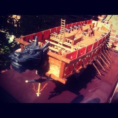
The Barbette for the 30.5 cm Gun
The barbette mainly consists of a semi-circular breastwork armour, backed by hardwood and by an open space covered with thin plate. The latter presumably to retain splintering wood in case of an impact. Since no tube of suitable dimensions for the breastwork was to hand, I made a short, laminated one from Bristol board layers glued together with white glue. The edges were soaked in thinned white glue before being trimmed down on the lathe. The tube then was varnished with wood-filler before the edges were sanded. Finally the tube was cut into half on the fret-saw. More wood-filler was applied before final sanding. The other inside wall of the barbette were lined with Pertinax to provide a smooth surface.
Trimming the laminated tube on the lathe
The fore-deck has been covered in a sheet of thin Bristol board and the camber of the wooden decking built up with an additional piece of board and putty (I am using fast drying bodywork putty from car repair suppliers). The anchor pockets have also been lined with thin Bristol board, but Pertinax would have been better for this.
Tube for the barbette armour made from laminated Bristol board
All surfaces that would have been iron plating, will be covered in thin sheets of Pertinax. The necessary holes for portholes and other opening will be drilled or cut before the sheets are fixed.
In between, I had also improvised a disc-sander from a PROXXON router. In think in the meantime this manufacturer offers a small disc-sander.
Smoothing the hull on the newly constructed disc sander
To be continued ...
-
wefalck got a reaction from Tadeusz43 in SMS WESPE 1876 by wefalck – 1/160 scale - Armored Gunboat of the Imperial German Navy - as first commissioned
Deck Fittings
The hull taking shape, at least in its rough outline, I turned my attention to some pieces of deck fittings. I know, many modellers more or less complete the hulls etc. including the paintwork first, but as many pieces may require repeated handling and fitting on the hull, I leave these finishing touches to the end.
Bollards
The ships were fitted with four pairs of bollards of square cross section; two at the rear and two on the raised quarterdeck. Luckily a good, rather close-up photograph of the real specimen is available.
Rear deck with emergency steering stand and other pieces of deck fittings
The bollards are milled from round brass stock. Round stock was chosen as a starting point rather than e.g. flat stock, because it can be held easily in the lathe for turning on a spigot, by which the part can be held for further machining. Otherwise it would be difficult to mount such a small part on the miller for machining on five sides. The spigot is a convenient reference for machining and for fastening the part on the model eventually.
Indexing head on the milling machine
Before the milling operations
From the lathe the raw part is transferred to an indexing head mounted on the milling machine. After each pass with the cutting tool, the part is turned by 90º or 180º depending on requirements. Thus a square and symmetric part is produced.
Milling nearly completed
For a final machining step, the part is transferred back to the lathe and the dome shaped head formed using a very fine file on a roller-filing rest.
The nearly finished bollard with the roller-filing rest in the foreground
The job is completed by rounding off the corners using a not-too-hard rubber-bonded abrasive wheel (CRATEX) in the mini-drill. Remaining machining burrs are removed by offering the part to wire brush wheel.
The bollards on part of the working drawing
To be continued with the bases for the bollards ...
-
 wefalck got a reaction from robin b in SMS WESPE 1876 by wefalck – 1/160 scale - Armored Gunboat of the Imperial German Navy - as first commissioned
Deck Fittings
The hull taking shape, at least in its rough outline, I turned my attention to some pieces of deck fittings. I know, many modellers more or less complete the hulls etc. including the paintwork first, but as many pieces may require repeated handling and fitting on the hull, I leave these finishing touches to the end.
Bollards
The ships were fitted with four pairs of bollards of square cross section; two at the rear and two on the raised quarterdeck. Luckily a good, rather close-up photograph of the real specimen is available.
Rear deck with emergency steering stand and other pieces of deck fittings
The bollards are milled from round brass stock. Round stock was chosen as a starting point rather than e.g. flat stock, because it can be held easily in the lathe for turning on a spigot, by which the part can be held for further machining. Otherwise it would be difficult to mount such a small part on the miller for machining on five sides. The spigot is a convenient reference for machining and for fastening the part on the model eventually.
Indexing head on the milling machine
Before the milling operations
From the lathe the raw part is transferred to an indexing head mounted on the milling machine. After each pass with the cutting tool, the part is turned by 90º or 180º depending on requirements. Thus a square and symmetric part is produced.
Milling nearly completed
For a final machining step, the part is transferred back to the lathe and the dome shaped head formed using a very fine file on a roller-filing rest.
The nearly finished bollard with the roller-filing rest in the foreground
The job is completed by rounding off the corners using a not-too-hard rubber-bonded abrasive wheel (CRATEX) in the mini-drill. Remaining machining burrs are removed by offering the part to wire brush wheel.
The bollards on part of the working drawing
To be continued with the bases for the bollards ...
-
wefalck got a reaction from GrandpaPhil in SMS WESPE 1876 by wefalck – 1/160 scale - Armored Gunboat of the Imperial German Navy - as first commissioned
S.M.S. WESPE (HENK, 1895)
History and context
The WESPE-Class armoured gun-boats of the then young Imperial German Navy were born out of a tactical concept that dated well back into the Napoleonic era. The idea was to mount a heavy long-range gun onto a highly mobile small craft that would be able to retire into shallow coastal waters, beyond the range of even the heavy artillery of an attacking fleet. The addition of a steam engine and the increase in calibre followed the development of the time, of course. Adding heavy armour to the front (mainly) was meant to give the gun-boats a certain attacking capability. It also owes something to the floating batteries used in the defence of Copenhagen during the Napoleonic wars and to the armoured floating batteries used by the allied French/British forces during the Crimean War (1854-55). In fact, adding armour plating to a (rowing) gunboat was already proposed as early as the late 18th century in Spain, as documented by a model in the Museo Naval in Madrid, but apparently never put to work in full scale.
S.M.S. WESPE, brand-new and still without the 30.5 cm gun (1875)
At the time of the conception of the WESPE-class in the early 1870s a former cavalry(!) general was the naval chief-of-staff in Germany. The tactical dogma was ‘proactive defence’: an attacking enemy was to be awaited near home waters and fenced off. The main threat was seen in amphibian operations attacking the German coast. Thus, the landing of troops at strategic points had to be prevented. Long-range strategic and oceanic operations were out of the scope of the German naval planners of the time. There was a certain logic in this, as Germany, unlike Britain, is/was a more or less land-locked country and largely self-sufficient in many respects at that time. Overseas trade then did not have such an importance as in Britain or as in later globalising economies. Therefore, attempts to severe overseas supply chains was not so relevant. There was, indeed, active resistance from trade interest groups, particularly the merchants in the cities of Hamburg and Bremen, to a navy that would engage itself overseas. These merchants relied on their network of friendly contacts and on sailing under a neutral flag.
Hence, the WESPE-Class was designed to be mainly a heavily armoured gun-platform, giving long-range protection to the tidal North Sea harbours that are surrounded by mud-flats and to give mobile protection to the deep fjords of Schleswig-Holstein's Baltic coast. They would be backed-up by heavy artillery (and later fixed torpedo batteries) in coastal forts.
The guns in such boats usually could only be trained by turning the whole boat. This seems more difficult then it probably was, because even in the old days of the rowing gunboats they would attack by rowing in a wide circle and when the intended target passed through the line of aim, one would fire. As the WESPE-Class was designed to let themselves fall dry on mud-flats, a possibility to train the gun itself was needed.
This distinguished the WESPE-class from earlier boats of similar design in Britain, namely the ANT-, GADFLY-, and BOUNCER-class of the 1860s. Man other navies took up the same concept and there were examples in the Danish, Dutch, French, Norwegian, Spanish, and even the Argentinian navy. Some of the were armoured, while other were still constructed from wood or composite.
S.M.S. WESPE under construction (HENK, 1895)
Technical Description
The WESPE-class comprised ten boats delivered in two batches between 1876 and 1880: WESPE (1876), VIPER, BIENE, MÜCKE, SCORPION, BASILISK, CAMAELEON, CROCODILL, SALAMANDER and NATTER. They were all built by A.G. Weser in Bremen. With a length of 46.4 m and a beam of 10.65 m they had a dead weight of 1157 t, drawing 3.37 m. The dimensions vary somewhat according to source, but this may be due to different reference points, such as length overall compared to length between the perpendicles etc.
Two inclined double-expansion engines on two propellers gave a maximum speed of 11 knots. Their original complement was 3 officers and 73 crew. Steering was from a stand on the hut and an emergency double steering wheel abaft. Very early on they were also retrofitted with an electrical generator.
The WESPE-class were the first German warships (and indeed among the first of any warship) that did completely without auxiliary sails. As the consequence they only had a light mast for signalling. In spite of sporting quite some leading edge technology, they were only of limited seaworthiness and their handling was far from perfect. This resulted in them being given a collection of rather unfavourable nicknames. They were also not very popular with their crews and officers due to the cramped conditions below decks, but then they were not meant for long voyages in the open sea.
Admiralty illustrative drawing (before 1883)
Armament
The main armament was a single 30.5 cm rifled breech-loading gun designed and manufactured by Alfred Krupp AG in Essen. At the time the WESPE-class boats were designed, fast torpedo-boats did not exist yet – the automotive fish-torpedo was just being developed. When in the mid-1880s small torpedo-boats became a tactical reality, some form of self-defence against them was necessary and two bronce(!) 8.7 cm/l24 breech-loading guns in ‘disappearing’ carriage and two 37 mm Hotchkiss revolving guns came on board. In fact, very early on (1883) also two 35 cm underwater torpedo launching tubes were installed to increase the attacking capabilities.
Instruction model for the Rk 30.5/l22 on the Danish HELGOLAND in the Orlogsmuseet Copenhagen on a carriage similar to that of the WESPE-Class
Scale
The scale chosen for the model is 1/160, which admittedly is somewhat unusual for a ship model. However, the reasoning behind this choice was that a large selection of N-scale railway figures is available that eventually will crew the ship. There are also space and portability consideration, which are important for someone, who has to move from time to time for professional reasons.
The model will be a waterline model. This will allow a scenic presentation of the finished model. Besides, the hull below the waterline is not quite so graceful. Above the waterline the hull is also more or less prismatic, with vertical bulwarks and virtually no sheer. These parameters together call for a bread-and-butter construction.
Artist’s impression of a WESPE-Class gunboat (1891)
Sources
Owing to the loss of most of the archival material from the former Admiralty Drawing Office during and after the end of WW2, detailed source material is rather scant. Some lithographed drawings that must have been made before the major refit in 1883 have survived and serve as a basis for the reconstruction. The Bundesarchiv/Militärarchiv in Freiburg i.B. has some drawings, but unfortunatelly they only pertain to a much later refit of S.M.S. NATTER. However, the WESPE-Class was a bit of a novelty at its time and some Detaildrawings of bothm the ship and the armament, have found their way into textbooks of the time. Relatively recently a very detailed original drawing of the gun became available on the Internet from a private collection (www.dreadnoughtproject.org). Historic photographs from the early days of the ships are quite rare and mostly of not so good quality, but some reasonably good ones from the end of their active life have survived.
Based on the information that was available in the 1980s Wolfgang Bohlayer drew and published a plan of S.M.S. WESPE as she might have looked like after the major refit in 1883 (available from VTH, http://shop.vth.de/wespe-1876.html). Based on the information available today, this plan would need to be revised in some details.
The available information is summarised on the page on the WESPE-class on my Web-site: http://www.wefalck.eu/mm/maritime/models/wespe/wespeclass.html
To be continued ...