


bhermann
-
Posts
536 -
Joined
-
Last visited
Reputation Activity
-
 bhermann reacted to EdT in Young America 1853 by EdT - FINISHED - extreme clipper
Young America - extreme clipper 1853
Part 30 – Aft Square Frames 2
At this stage the first 15 full frames aft of 0 have been set. The first picture shows frames 16, 17 and 18, right after inserting their bolts. These are ready to be installed.
The next picture shows the hole being drilled for a pin on the port side of frame 16. A bent pin in this hole will secure the top on this side of the frame to the ribband strip.
I mentioned earlier that a wood block is used to space the frame and the caliper to set the height of the ribband to the bottom of the planksheer rail. That rail will be added much later.
The next picture was taken after frames 16 and 17 were erected.
At this stage the ends of the temporary ribbands were reached. The next picture shows work to extend the ribbands. Setting frames using the ribbands has been a major time saver and helped get the frames into faired lines.
Connecting strips are being glued to the bottom of the existing ribbands. The next picture shows the ribband extensions being glued on. The “gantry” is being used to hold clamped guides the set the height and breadth of the ribbands at that position along the hull.
The gantry can be moved and the guides set at any given position. The next picture shows another view of the hull with the extended ribbands.
In the last picture frame 18 has been installed and pinned to the ribband extensions.
The length of the hull – and the eventual size of the model are starting to become apparent. It is really long and slender. By way of comparison, Naiad was 147 feet long with a breadth of roughly 39 feet – an L/D ratio of roughly 3.7 to 1. Young America had a length of 240 feet and a breadth of 43 feet – an L/D ratio of 5.6 to 1.
There are now 11 more full frames to install. 19, 20 and 21 are in fabrication. 22, 23 and 24 have been lofted. After installing the last full frame - number 29 - the keelson and aft deadwood assemblies will be completed to prepare for the half and cant frames.
Ed
-
bhermann reacted to Modeler12 in A video about attaching blocks to spars and masts
Thanks to Bender (and with his permission) I have put together as brief video about how to rig a block to a spar, mast or gaff.
I hope this may be of some use to you.
-
bhermann reacted to Rustyj in Bomb Vessel Granado by Rustyj - FINISHED - 1:24 - cross-section
Thanks Greg. Not much, maybe 1/64”. I always over bend them hoping to
compensate for the spring back.
Thanks grant. It’s always fun for me to mix in different woods.
I’ve milled all the holly needed for the decking and have started laying them.
Again I am using black paper to simulate the caulking. Hopefully later tonight
I well get to the area around the hatch completed.
-
bhermann reacted to rwiederrich in Donald McKay 1855 by rwiederrich - medium clipper
Now that the build up is finished...I'm going to lay out the main cabin and prepare for the decking that will extend from the forecastle to and over, forming the roof of the deck house. a single gang way will proceed from this to the poop deck. I'll finish off the forecastle front and doors at that time.
Before all that I will install the bulworks timbers and the waterways..
Rob
-
 bhermann got a reaction from DaveGrady1 in Size of blocks for MS Bluenose 1/64 scale.
Dave - I'm sorry to hear the blocks are no longer supplied. It seems that several things have disappeared over time (the walnut veneer for the second planking was the first item I am aware of that went missing from later kits).
My older version does have the 7/32 blocks included. They look a bit oversized to me. If you are going to purchase blocks I'd recommend going down in size - the 5/32 might do the trick. Are there enough of those in the kit to substitute for the halyard blocks? Or as Allan said, making your own blocks is an option. There are some threads on MSW that describe peoples techniques for doing this.
BTW - I'd love to see photos of your work so far - or even a build log if you are of a mind to do so. The more Bluenoses out there, the better! And welcome to MSW.
Bob
-
bhermann reacted to Hank in USS NEW JERSEY (BB-62) 67-69 by Hank - FINISHED - Trumpeter - 1:200 - PLASTIC
Purchase of the Trumpeter 1:200 MISSOURI kit took place the last week of Nov. 2013. I received the kit today, Dec. 05, and began to access what was needed to turn this into a model of USS NEW JERSEY (BB-62) in her 1967-69 configuration.
As for reference materials, I will be using various sources in order to obtain the best information possible for this project. They include, but are not limited to:
USS MISSOURI Plan Book – 1945 - The Floating Drydock
Battleship NEW JERSEY – Paul Stillwell
IOWA Class Battleships - Robert Sumrall
United States Battleships, 1935-1992 - W.H. Garzke, Jr. & R.O. Dulin, Jr.
Photoetching for the Plastic Ship Modeler - Loren Perry
Dreadnaught Returns & Dreadnaught Farewell – Neil Leifer
Dreadnaught 68-69 - 1968-69 USS NEW JERSEY Cruise Book – LTJG J.T. Vernallis, Editor
USS NEW JERSEY – The Navy’s Big Guns – Neil Leifer
Warship Data – USS MISSOURI (BB-63)
Warship Data – USS IOWA (BB-61)
The IOWA Class Battleships – Malcolm Muir
U.S. Battleships – An Illustrated Design History – Norman Friedman
USS NEW JERSEY (BB-62) Plans –
Floating Drydock – Deck Plan/Sheer Elevation – 1967 – Tom Walkowiak
Floating Drydock – G Series, from U.S. Navy Plan Book
In addition to the plans/publications listed above, I will be referencing photos taken by myself aboard NEW JERSEY and those of Tom Fally in visits to MISSOURI (BB-63) in Pearl Harbor, HI.
The model will be bashed as necessary to achieve the 1967 renovations made to NEW JERSEY at the Philadelphia Naval Shipyard. Those include: removal of all 40mm AA batteries, removal of various HVAC ventilators and repositioning; the addition of the UHF antenna on the bow of the ship, addition of the 4 ABM Chaff Launchers (modified Zuni Rocket pods), modification to the forward fire control tower with addition of the ECM suite, modifications to the forward/aft masts and radars, addition of the helo pad on the fantail and supporting equipment, and various other minor changes made to the ship at that time.
In addition to the basic kit, Teak Decking will be installed over the kit deck on the main deck and 01-04 levels as well as photoetched details will be utilized in place of plastic parts from the kit. These are or will be provided from a third party vendor.
Vendors under consideration are:
Pontos – Basic PE Detail Up Set w/o Deck (purchased)
Scaledecks – Uncut Teak Deck sections as necessary
Nautilus Models – Uncut Teak Deck sections as necessary
Toms Modelworks – PE Doors & Hatches (purchased), Upright Stairs & Ladders, and various other PE deck equipment and fittings
Gold Medal Models – 1:200 scale U.S. Navy Decals (purchased)
At this point I've done an initial assessment of the kit and have a couple observations to make:
1) The PE provided in the kit has been evaluated for it's strength (thickness) and may be used where appropriate. In addition, the Pontos Teak Deck Detail Set may be purchased for the 01-04 Level decks and PE equipment - the main deck is not suitable for this build. Under consideration is the uncut Teak Decking from Scaledecks which will be fashioned for the main deck of the model.
2) Kit provided decals are deemed not suitable for this build - GMM decals were purchased and will be incorporated throughout.
I am still looking over choices for solvent based paints to be used (Haze Grey/Deck Grey). I've decided on Gundam Mr. Color #29 – Hull Red (Bottle) and GSI Creos Mr. Color Hull Red (Spray) for used on the models bottom (paint purchased).
So, for the initial "eyes-on" of the kit, I'm fairly satisfied with what I've seen so far. There has been some discontent by other modelers as to the hull of this model and whether or not it's underside faring aft of the skege keels down towards the inboard shaft skegs is correct. I am not going to get into this argument at this time - there's a lot of other decisions to make before deciding that the hull needs revamping - a major task to be sure.
Once my shop area has been policed, inspected, Field Day held, and all scallywags, drifties, slackers, and any other riff-raff taken to the brig, construction will commence.
Hank
-
bhermann reacted to gil middleton in HMS Victory by gil middleton - FINISHED - Caldercraft - 1:72
Lawrence, I'm glad it helped.
Modelman, Will not likely get to Finland again but we'll be in touch through MSW.
Ron, Thanks, but your brig "Oneida" is a gem. What a great transition from kit to scratch building. The decking and planking is exquisite and I am so glad I can paint over my mistakes. If I live long enough, perhaps I'll handle wood like you do.
Continuing on with the main course clew garnet (clew line), clew block, tack and sheet. The main sheet brackets and ring supporting the aft sheet block.
A side view for orientation, showing the fore yard tack going forward to the boomkin and the fore yard sheet going aft. Also showing the main yard tack.
The fore yard sheet running down to the right. The main yard tack, down to the left.
The main yard sheet, originating from an eyebolt in the hull, passing through the sheet block, returning to the aft sheet block, supported by a lanyard through the bracket and ring.
One could argue that the sheet interferes with the gun port lid, however, when clearing for action, the courses (lower sails) were generally furled to avoid the firey wad being blown back into the sail causing the sail to catch fire. Have we all read the Patrick O'Brien series? Cheers, Gil
-
bhermann reacted to EdT in Young America 1853 by EdT - FINISHED - extreme clipper
Young America - extreme clipper 1853
Part 29 – Aft Square Frames
Framing aft of frame 0 has been proceeding well over the past few days. I have adopted a new alignment method that I will describe in this part.
The first picture shows frame 1 installed. Instead of using temporary wood chocks to hold frame alignment and spacing, I decided to try and use the temporary ribbands. These are at the height of the planksheer. I left them long, anticipating this.
The next picture shows more frames installed.
The heights of the cross-spalls in this picture are irregular because they are set down on the aft top timbers and these have been left slightly long for cutting down later. Each spall sets the breadth of the frame accurately, however, and is center marked.
The next picture shows another view of the overall hull, and displays the normal cluttered state of the shipyard.
Another view from aft.
In the next picture, an assembled frame – frame 9 – with its patterns still on, is being test fit after beveling.
All of these frames are being pre-beveled to the lines on the patterns. The next step is to remove the patterns and downsize the sidings of the upper timbers. This cannot be done until the frames are beveled and the patterns removed.
In the next picture the frame has been clamped to the ribbands at the top and positioned accurately with its floor centered down on the keel. The maximum breadth of the frame is then checked by squaring up from the base drawing. A hole for the model bolt is being drilled.
Because of interference with the spall, the hole will be angled aft slightly. A short pin is then inserted to hold the position. The clamps are then removed and the frame lifted slightly to spread glue on the keel. The pin is then driven home to secure the joint.
Before the glue has set the toptimbers are aligned using the spacer block in the next picture. The caliper is set from the drawing to the height of the bottom of the planksheer rail so that will be at the correct height at each frame..
The next picture shows a closeup of the spacer block. Its width has been sized to 23” – the spacing between frame lines in the area (32”) minus the siding of the toptimber (9”)
A pinhole has been drilled through the toptimber and the temporary pin bent over to hold the frame tight to the ribband. The half breadth of the frame is then rechecked using a square from the the line on the base drawing.
This method is not only much faster and less messy than using the spacers, but pulls the frames into a fair line at the top. If made to the pattern and beveled accurately to the profile lines, the frames should be pretty well faired when erected. So far, that is the case. We will see how this holds up as the bevels increase with each new frame going aft.
Ed
-
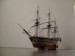
 bhermann got a reaction from Fright in Bluenose by bhermann - Model Shipways 2130 - 1:64
Next up "logically" would be the nameboards. I printed up some decals by scanning the detail from the plan, changing the color from black to yellow in MS Paint, then printing them on clear inkjet decal paper.
The only problem is that when the decal gets applied to the black background, the yellow disappeared completely.
Try #2 - thanks to advice from Floyd - was to reprint the decal with a black background and apply that onto a piece of wood that is painted white.
Here is the final result glued in place.
Bob
-
bhermann reacted to sparrow in Royal Caroline by sparrow - Mantua/Panart - Royal yacht 1749, scale 1:47
Hi Bob,
thank you for your comment and suggestions. I have finally given up with the colorful print and instead I used office white paper that I covered first with golden color and then printed with black only. Then I needed to cut out the pattern and apply a little of golden color on the edges so that the white would not be seen.
See the pictures...
I think the golden scheme looks better and does not stand out so much in contrast to the other ornamentations.
Cheeers,
Jan
-
bhermann reacted to EdT in Young America 1853 by EdT - FINISHED - extreme clipper
Young America - extreme clipper 1853
Part 28 – "Pin-Indexing"
Next on the agenda is a long slog of repetitive work – making and setting the 29 full frames of the afterbody. This will be followed by 13 pairs of half frames and 6 pairs of cants – then the eagerly anticipated circular stern
Essentially, this framing will be a repeat of the installation in the forebody. I previously showed pictures and described the frame assembly using pin-indexed pieces. This has greatly improved efficiency and accuracy in assembling the 13 pieces of each full frame pair. This process can only be used if indexed bolt/pin holes are provided on the pattern sheets. I thought it might be interesting to give a short overview of how that step in the lofting process was done.
I put this post together a few days ago thinking I might post it. The discussion on pre-beveling of frames prompted me to do so, since the lofting described is one of the enablers for that.
This is an overview only of the pin/bolt hole placement on the patterns. I will not describe the entire frame lofting process here, except to say that profiles for the true fore and aft faces of each frame must added to the normal body plan and used for lofting beveled frames. Using profiles from the next frame forward and aft does not provide sufficient accuracy for bolt placement in beveled frames.
The first image shows the fore and aft half-pattern objects for forward frame R, created from the enhanced body plan.
In each pattern green is used to show the forward profiles and red for the aft profiles.
Every frame “bend” on Young America is constructed with offset, sistered fore and aft timber segments. The segments are delineated by the cut lines on each pattern. In this image no pin holes have yet been placed on either pattern, but the objects for the hole marks are scattered to the left of the forward pattern.
The two patterns are then aligned to their final relative positions as shown below.
This is a highly beveled frame pair, as can be seen in this image.
With the patterns aligned, the pin/bolt hole objects are placed on the combined patterns between the line for the forward outboard profile and the aft inboard profile. This assures that they will not break through either the inboard or outboard faces – hence the need for accurate profiles. The placement of some of these near the top of the frame is shown below.
In this highly beveled frame, these hole objects just fit between the lines. The actual pin/bolt holes will be smaller than these objects. Note that the top of the forward frame is higher since it includes the stanchion for the main rail.
With the holes placed, the aft frame pattern object is selected along with all of the hole objects. This combination is then copied and pasted to the right in the next image. The aft pattern is then deleted from its position atop the forward pattern leaving just the forward frame and the original hole objects in place. The two pattern halves now have precisely indexed pin/bolt hole marks.
The two objects in this image are then mirrored and combined to form the full frame patterns shown below. This same basic process is also used for the half and cant frames.
After cutting out the timber segments, the patterns can then be used to drill indexing pin holes to locate the timbers on a pattern sheet for assembly and later for insertion of model bolts. This was described in previous posts.
Assembly accuracy is very dependent on accurate drilling, but that is another topic. Besides the advantages in assembly time, the final frame emerges with patterns on both fore and aft faces – one of the important enablers for pre-beveling before erection.
I believe this process has reduced the frame assembly time to half of what I expected so far. The above description is, of course, simply an overview, hardly a tutorial.
The jury is still out on whether this and the other process features will enable frames to be completely beveled before erection.
Sorry, no photos. Next time.
Ed
-
bhermann reacted to EdT in Young America 1853 by EdT - FINISHED - extreme clipper
Young America - extreme clipper 1853
Part 27 – Forward Hull Sanding/Bolting
First, thanks everyone for the recent comments. I hope all those who celebrate Thanksgiving Day had a good holiday.
The view from directly forward in the last post seemed popular so here is another from a slight angle.
All those unsightly wood spacers between frames are temporary and will be coming out at some point.
After this picture was taken the model was inverted for fairing and sanding. There is not much to say about this, since it turned out to be less work than anticipated. Below is a picture of part of the bottom after sanding.
Not much fairing was needed – nothing like the work I had to do on Naiad, where very little pre-beveling of frames was done. On this model almost all of the beveling was done before the frames were set, so the sanding was mostly for cleanup and finishing.
The next picture shows an area slightly forward.
This picture shows some of the bolts – inserted after sanding – to secure the half frames to the keelson/deadwood. These are copper wire, epoxied deep into the holes to give strength to the model joints. These frames are end-grain glued to the keelson/deadwood, so the joints are not strong. These bolts were iron so they will be blackened before the lower hull is finished.
I am considering installing the garboard strakes – at least – later on both sides. On these ships the garboards had an important structural role. They were quite thick (7”) and were edge bolted through the keel and face bolted to the frames. This reinforced the attachment of the frames to the keel and will serve that purpose on the model as well. You will recall that the frame floors are merely glued and pinned to the top of the keel – not notched to fit over a rising wood as in 18C ships – and some clippers. This is not a strong joint.
While the model was inverted the remaining forward bolts were installed. The bolts through the stem can be seen in the next picture. These were long copper bolts.
Eventually, the forward side of the stem – actually the false stem – will be tapered down to about 4 or 6 inches in `breadth.
The last picture shows the iron bolts securing the hawse timbers to the stem/apron. Like the cant frame bolts, these are black monofilament. All these bolts were riveted flush.
The model has now been re-aligned on the shipway so the afterbody framing can begin.
Ed
-
bhermann reacted to gil middleton in HMS Victory by gil middleton - FINISHED - Caldercraft - 1:72
A bit more on the clue, sheet and tack blocks. The photos I have of the Victory show the blocks held together with shackles (which hadn't been invented in 1805. McKay's drawings show a monkey fist and loop arrangement. I've simply prepared the blocks and lashed them together. I suspect McKay's illustration is more accurate. Fashioning the clue block. All line including the strop and eyes are served. Brass rod used to maintain the eye.
One eye completed.
Forming the second eye.
Sheet block
-
bhermann reacted to Elia in Arethusa 1907 by Elia - Knockabout Banks Fishing Schooner
Shipwrights - it has been a long time since I last posted progress on Arethusa. I have been working away on her, in little snippets of time here and there. Springtime turned to summer, when my modeling usually all but ceases, replaced by outdoor activities. Autumn typically welcomes the shipwright (me!) back to his work shop. This year my wife and I decided to embark on a large home improvement project and it has taken far more time and energy than initially estimated. That resulted in less model time than I had hoped for. I am now getting a little modeling time in and following are some progress photos.
The saga of the yellow cove stripe is almost over. I had removed the offending strip of wood, per my previous postings, glued in the repair strip, and spackled, sanded and faired it. I then painted the yellow stripe region. After the painted dried for a couple of days I applied the 1/64” wide masking tape. It was surprisingly difficult for me to get it to run straight and true along the new piece of wood. ?! Once in place I painted a light coat of the yellow over the masking tape to seal its edges for bleed under by the black topcoat, which followed. The resulting stripe looks thin and yellow, as desired, though it wanders a wee bit. I think I’ll live with it. As you can see if the accompanying photo I’ve added some white to the scuppers. All of my remediation work had filled in the scuppers with spackle, sanding dust, primer, and paint. I cleaned out the scuppers and applied some of my white paint as touch-up. Once the chainplates are attached I’ll apply black topcoat and it should look tidy (at least that is the plan).
Speaking of chainplates - I have been working away on those details. First off was making the deadeyes. Ron (Oneida build) was very helpful in providing me a direction in which to proceed regarding making my deadeyes. I followed his lead, similar to Harold Underhill, in making a jig to locate the lanyard holes and setting the height of the deadeye.
I don’t know if you shipwrights ever see a detail on the full size ship that just sticks with you and you find you need to model it, but that happened to me on the deadeyes. The large Gloucester schooners had deadeyes which were iron stropped to the chainplates. That in itself isn’t unusual. What is unique (in my mind at least) was that the strops were double wire loops. Not one, but two iron strops restrain the deadeye to the chainplate. I had purchased britannia deadeyes from Blue Jacket Shipcrafters for Arethusa but upon inspection I found I could not easily make the purchased deadeyes accept the double iron strop arrangement. Thus I set off on making the lower deadeyes. I used boxwood as it is hard, has little grain direction, and cuts and sands cleanly.
The larger deadeyes on the larger schooners were 7” to 7 1/2” in diameter and the width was about 5”. On my model the ones I’ve made are 0.160” diameter (4mm) and 0.10” thick. The smaller lower deadeyes were 5 1/5” in diameter, and my model ones are 0.115” diameter (3mm). Interestingly these double stropped deadeyes are essentially flat faced, making fabrication a little easier.
My deadeye fabrication process was as follows:
Shape wooden rod from square stock using chisels to form first an octagon, chuck it in a hand drill, and use progressively fine grits of sandpaper to sand to the final deadeye diameter.
Using the little jig and a pin vise drill the three lanyard holes.
Chuck the dowel in my benchtop drill press. Use the jig to mark the final width/cut of the deadeye with a fine kerf saw (on the drill press).
Use a triangular section file to create the strop grooves (on the drill press). This was the most inconsistent part of my process as I didn’t have (or use/implement) some ‘tool rest’ with which to steady the file. Remove the deadeye from the drill press and saw off the deadeye at the previously marked line.
Finish drilling through the lanyard holes.
I eased the holes with a micro “V” shaped gouge, followed by using the lanyard hole drill bit in the pin vise, rotated slowly, and angled to create a shallow groove. All edges were then lightly sanded.
I have made the chainplates, both (16) longer ones for the lower shrouds and (4) shorter ones for the upper shrouds. I used a jig to locate the chainplates for drilling the bolt holes. The upper loops are soldered. A few extras were made as I typically lose or mess up some when working through the fabrication steps.
I have fabricated the jumbo, jib, and flying jib stay ironwork from brass sheet stock.
I have made some cleats:
And some chocks:
And for the deadeyes I have begun making the double iron strops. Here is a photo of my jig for forming the strop from 26 gauge brass wire. I solder the one loop end, trim off the excess wire, and file it to resemble a hoop end. I then use a larger drill bit shank to wrap the double strop around and straighten the hoop ends.
Once the strops are complete I'll proceed with assembling the deadeyes to the chainplates. I intend to stain the deadeyes black and paint the strops (before attaching them to the deadeyes) dull silver (for they were galvanized). I'm scheming now on how to solder the bolt and nut hardware, joining the iron strops to the chainplate.
Hopefully it won't been almost a year before I post further progress!
Cheers,
Elia
-
bhermann reacted to gjdale in HMS Victory by gjdale - FINISHED - Mamoli - Scale 1:90
Thanks again everyone for the kind comments and the likes.
Progress is once again at a glacial pace as life seems to have a habit of getting in the way at the moment. Nevertheless, I did manage to progress a bit further with the yard preparation today.
I made an interesting discovery in my wife's favourite sewing shop today - "self-threading" needles. And they work!
I received some more of Chuck's excellent rigging thread in the post this week, so was able to start on the stirrups. I must admit to once again being inspired by the work of Blue Ensign on his outstanding Pegasus build. He is just far enough ahead of me in progress terms to be an excellent source of guidance and inspiration. So my method for the stirrups follows pretty closely to his.
It starts with forming a "false splice" in one end of the thread. I'm using 0.30 mm black thread for my stirrups, which is pretty close to scale for the 4-inch circ. rope used at full scale. I've chosen to do my stirrups and horses in black, which may or may not be correct, but is consistent with my choices for hammock netting and ratline colours. The method of forming the "false splice" is borrowed from Gil Middleton, repeated by Blue Ensign, and now by me.
A needle is used to thread the line back through itself:
And then back through a second time:
The completed "splice" looks like this:
The splice is then placed over a 1mm diameter brass rod held in a Fly-tying vice (thanks Mobbsie for that idea ) :
A dab of CA is applied to the splice and around the eye, which is then carefully removed from the brass rod:
The stirrups are then attached to the yard, being wrapped three times around the yard, with the "fall" of the stirrup lying on the aft side of the yard, and outboard of the turns. A dab of CA is applied and once set, a small weight is applied to the fall of the stirrup and the entire stirrup painted with diluted PVA and left to dry overnight. Tomorrow I will add the horses.
You can also see in the picture above and the next below, the Truss Pendants, which have been fitted with a brass thimble and seized to the yard. Note that the thimble lies down on the starboard side and up on the port side (as per Longridge pg 240).
If I can finish the horses tomorrow, that will be the Fore Lower Yard complete. Only eight more yards to go! (then I will be able to say I've gone "the whole nine yards" )
-
bhermann reacted to rlb in US Brig Oneida 1809 by rlb - The Lumberyard - 1:48 scale - POF - Lake Ontario Warship
Finishing up the pin rails:
Here's how I revised them, so they continue around the aft post at the same height.
Moving on to the mast partners, I drew an octagon with at the correct size of my masts--
And milled the center out, a little smaller than the drawn octagon. Notice the wood is at an angle to account for the mast rake--
I filed the corners of the octagon a little better, then fit the partners on the deck. The octagons will need to be enlarged to fit the actual masts when they are made--
The aft hatch arrangement:
I finally settled on what to do with these last hatches. It's changed from my initial idea, and I needed to do some surgery to the framing to accommodate a companionway in the second opening--
I glued in a ladder I had made a long time ago--
Some pieces cut for the companionway sides--
The pieces that make up the sides were glued together, and when set they were sanded flush, trimmed to the right size, and glued into a "box"--
Just aft of the companionway, on what's left of the coaming, I'll build a binnacle.
The opening forward of the companionway will be a skylight. Here is the frame test fit--
And then both test fit together--
Ron
-
 bhermann got a reaction from Sjors in Le Mirage by Sjors - FINISHED - Corel - Wood - 1:75
Congratulations, Sjors. She turned out so well. I think the shots of the bow and stern really highlight her gracefulness and your craftsmanship. Well done!
Bob
-
bhermann reacted to Jim Lad in Francis Pritt by Jim Lad - FINISHED - Scale 1:48 - Australian Mission Ship
Another small update.
Yesterday I was able to get the planking rabbet cut on both sides plus some shallow grooves forward to locate the cant frames. Unfortunately our friendly electrician at the museum has done so well in providing extra lighting at the model makers desk that I found it impossible to get good shadow across the model to show up the rabbet line properly, but you can see it at the stern if you look for it.
I really must try and find some additional time for the Pritt or it will take the next decade to get anywhere.
John
-
bhermann reacted to guillemot in Scottish Maid by guillemot - FINISHED - 1/8" scale - Hall's 1839 Clipper Schooner
Some progress, rigging is a very long job when you're intending to add running rigging as well... Starting to look a bit more shipshape now. topmasts added, mast tackles, shrouds....
-
bhermann reacted to EdT in Young America 1853 by EdT - FINISHED - extreme clipper
Young America - extreme clipper 1853
Part 26 – Forward Half Frames/Ribbands
To provide space for work on the forward cant frames, I deferred setting of the remaining half frames. In the first picture that work is proceeding.
The next picture shows all of the forward frames installed.
The sleek forward hull shape is really visible at this stage. The next picture shows a different perspective.
And another view.
At this stage the alignment and spacing of the frames are set by the softwood spacers between each frame about midway between the keel and topside. More strength is needed for final fairing of the lower hull. Also, as the above photo shows, there is some irregularity in the line of the toptimbers that needs to be corrected before final fairing.
I decided to fair the forward hull before proceeding to the aft frames. To provide additional strength and align the frame tops I installed temporary “ribbands” on both sides at the height of the planksheer. I found this a very useful device in constructing Naiad.
The next picture shows the starboard ribband being fitted.
These were made from single 3/16” strips of clear white pine. One end was boiled to set the curvature and in the above picture is being clamped for drying. In the next picture installation is proceeding.
The strips are secured to every frame by short pins through drilled holes. These are bent over on the inside to pull every frame tightly into the fair line of the ribband. I cut off the points of the pins before bending to avoid all the scratches I got from these while working inside Naiad. The holes in the frames will later be used for sheer strake bolts. The tops of the strips are set at the height of the bottom of the planksheer rail, so these can be used to trim off the tops of the aft upper futtocks.
The next picture was taken from above after the strips were installed.
The center marks on the cross-spales cannot be seen under the thread line. This is a good thing. In addition to this centering check, the outside of the ribband was also checked by squaring up from the base drawing.
In the next picture I cleared all the clutter from the shipway to focus on the lines of the very sharp forward entry.
At this stage the frames have only been given the bevel described earlier before they were set. Some additional sanding to refine the fairness is needed.
The model can now be removed from the base and upended for sanding and also for installation of quite a few bolts, especially those holding the half-frames to the deadwood. These joints are quite weak so the model bolts will have to provide strength. I will cover this in the next post.
Happy Thanksgiving everyone.
Ed
-
bhermann reacted to ndeconte in Orca by ndeconte - FINISHED - 35" movie replica
So it's been a while since I posted, life has been busy for us here and it always seems that there's some new issue round the corner that needs to be attended to. I've had limited time recently to put into the boat, but I'm determined to get it done for Christmas!
I've added the lettering and the round cover plate to the back of the boat:
Here's a photo of the original lettering that was auctioned off from the boat, I used this to go by for the lettering.
Also added the re-enforcing plates, threaded rods and nuts to the locations on the hull. The rivet/bolt heads that are on the plates themselves are actually drops of 2 part epoxy, only way I thought of replicating them in this scale since nothing I found was small enough.
And I cut a master barrel out of a block of Ren-shape on the lathe, still have some re-working here and there and final sanding to do. Will be adding the 2 covers to the top then I'll make a mold off it and cast them in back urethane. Once this is done, I'll paint the appropriate yellow color and distress to match the origninals.
-
bhermann reacted to Rustyj in Bomb Vessel Granado by Rustyj - FINISHED - 1:24 - cross-section
Thank you Antony. Your continued support is very appreciated.
As I work my way around installing the ledges and carlings there are also
assorted knees, hanging knees and double knees.
All of the deck framing pieces are being cut from Cherry.
Here you see one set of double knees rough cut out.
Here is a hanging knee rough cut and then set in place to test the fit prior to the finish sanding.
Everything seems to be going well, so far, now hopefully I just didn't jinx myself!
-
bhermann reacted to DSiemens in Queen Anne's Revenge by DSiemens - FINISHED - ~1:1250 - BOTTLE
Thanks Michael.
I got her out of the plug. I used a razor blade to gut out the edges on top that were glued to the plug then put my pin drill into the top of the plug for leverage. A simple tug and she came loose.
I then drew the planks on another piece of paper cut out the deck and glue the deck in.
Now I got to figure out how to cut out the gun ports. There's supposed to be ten on each side.
I've been wanting to put an aprox scale on this ship but the size eludes me. I've found she was anywhere from 200 to 260 tons. I approximate that to around 80 feet long. This is all guesstiment based on length to tonnage comparisons I've made. If I'm way off let me know. if 80 is correct though 80 x 12 = 960. This model is an inch long so that would be 1;960. Since I can't get an exact though I won't put it in the title.
-
bhermann reacted to gil middleton in HMS Victory by gil middleton - FINISHED - Caldercraft - 1:72
SERVING LINES
The question has been asked about how to serve shrouds or for that matter, strops for blocks, lifts, or where ever serving is indicated. One is reminded that the large lines such as shrouds at the top were first wormed (passing smaller line in the crevices between the strands of the larger rope), then parcelled (wrapping with strips of canvas saturared with Stockholm tar) and finally served with a smaller line to protect from chaffing. The practical limit in modeling is serving, simulating all of the above.
Looking back in my log, I notice the tools are shown, but a method for serving is not. Among the different methods, some seem rather complicated. The following is perhaps one of the simplest.
The set up is shown with a serving tool available from "Ship Ahoy Models and Miniatures" held in place by temporary clamps. A spool of serving thread is on the left. One might guess that I'm left handed. For purposes of photography, I used a heavy line, 1.0 mm in diameter, as one might use for shrouds, with a serving line of less than 0.1 mm (Coats and Clark all purpose polyester coated polyester). For smaller lines such as strops for blocks, 0.5 to 0.25 mm, the serving line might be Coats and Clark "fine" polyester or Orvis round fly tying thread #12.. Magnification helps where passing a needle through small lines.
Measure the length to be served and place that part of the line tightly in the serving tool. If one is serving an entire shroud, the line can be moved until the entire line is served.
Pass a needle at the starting point
Thread the needle with the serving line and pass through the larger line.
Take 15 or 20 turns so that a droplet of fast (1 to 3 sec.) c/a can be applied only to the point where the serving line passes through the larger line.
Continue to take turns with gentle traction on the serving line to the length of serving desired and repeat passing a needle with the serving line through the larger line. Touch that point with fast c/a. After about a minute, trim off the extra serving line.
-
bhermann reacted to EdT in Young America 1853 by EdT - FINISHED - extreme clipper
Young America - extreme clipper 1853
Part 25 – Forward Cant Frames 2
American Clipper Note: William Webb foresaw the end of the extreme clipper craze. He came down to the dock to see Young America off on her first voyage in 1853 and remarked to the mate, “Take good care of her Mister, because after she’s gone there will be no more like her.” (Dunbaugh) Webb turned his yard to the future. Young America was his last extreme. Within the next few years there was a glut in clipper capacity and the premium freight rates they had enjoyed dropped off, ending demand for the type. Some were slow to see the change, but Webb’s yard continued to prosper building medium clippers, steamships and even a huge ironclad, finished too late to enter the Civil War.
This part will bring the forward cant framing to completion.
All of these frames were almost completely beveled before installation, as I became more comfortable with accuracy of the pin-indexed assembly. With patterns left on both faces of the assembled frames, each could be cut back to the green lines on the forward face and the red lines on the aft face using disk and spindle sanders. The sides were then shaved flat to those lines as shown below, using a carver's rasp.
This tool leaves a very smooth surface requiring little or no sanding. The work can be held by hand and/or with the aid of a vise.
The next picture shows the clamping of the second frame on the port side.
The clamping of these can be awkward, requiring long-reach clamps and gripping of angled surfaces. A starboard side frame is being installed below.
In the next picture the last frame is being installed – with simpler clamping. The position of each frame was checked with the square from the base drawing when glued in place.
Although the bevel angles of the joint faces were put on each pattern during lofting, there was still need for some refinement to get the proper installed angle. Each mortise also required some trimming for a good final fit.
With all the frames installed, fair lines for the bolt holes were drawn and the simulated iron bolts installed. In the next picture a black monofilament bolt is being cut off at the surface after gluing.
The excess CA glue was washed off with acetone and the bolts leveled off with a file. The next picture shows the finished bolting on the port side.
The last two pictures show the finished bolting - six 1 1/8" iron blunts per pair driven flush..
The thread line seen in these pictures was used to center the half frame pairs. It is hung by a weight off the center of the sternpost so it can be pushed out of the way or removed when required.
In the next part the remaining half-frames will be installed, completing the frame setting of the forward hull.
Work is progressing much more rapidly than I expected. I think this is mainly due to the pin-indexed frame assembly and the improved beveling method.
Ed