


clloyd
-
Posts
153 -
Joined
-
Last visited
Content Type
Profiles
Forums
Gallery
Events
Posts posted by clloyd
-
-
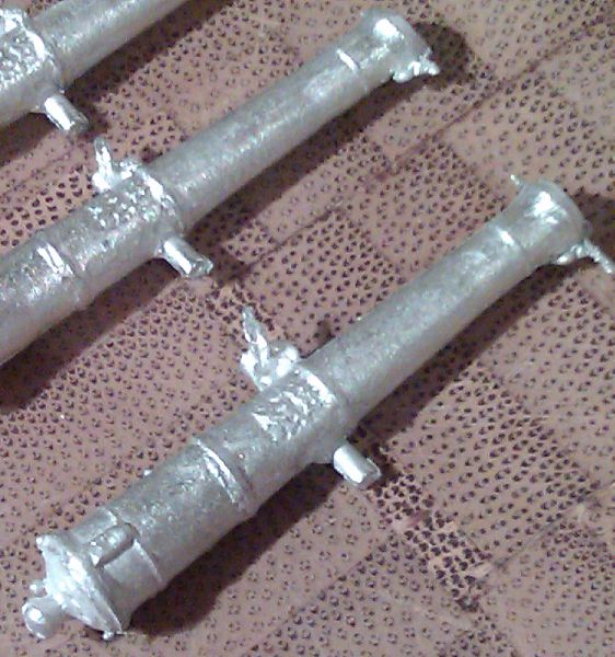
Armament:
Unable to find a 6pdr I liked I ended up making my own.
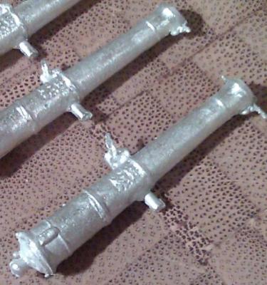
I took a commercial barrel that was at least the correct length and shape, ripped off the trunnions (because they were much more centre than lower 1/3) and replaced them, carved the design on the top of the barrel, added the flat section around the touch-hole. With my master done to satisfaction I then cast in whitemetal.
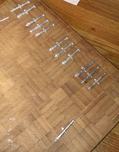
The foundry in full production.
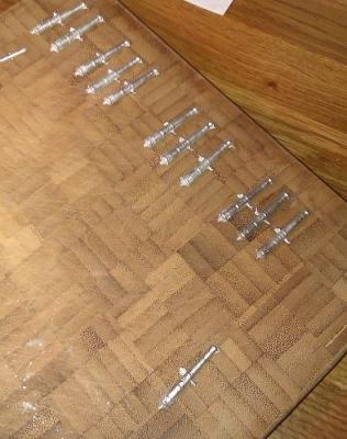
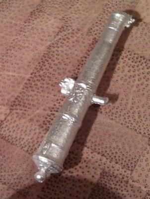
The freshly cast cannon before cleanup...
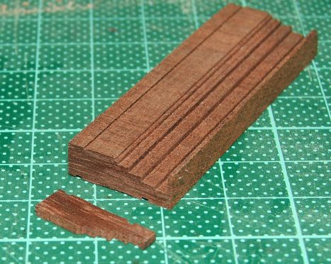
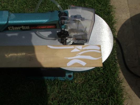
To start making carriages I shaped a single block of timber that I can then slice off individual carriage sides. I made sure the grain ends up running along the carriage side. The shaping was a matter of multiple passess through the tablesaw adjusting the blade height and fence accordingly.
I do have one cannon built, but can't find a photo of it, so I'll get a camera out and update this post when I get the chance.
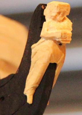
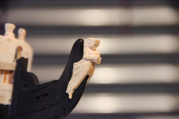
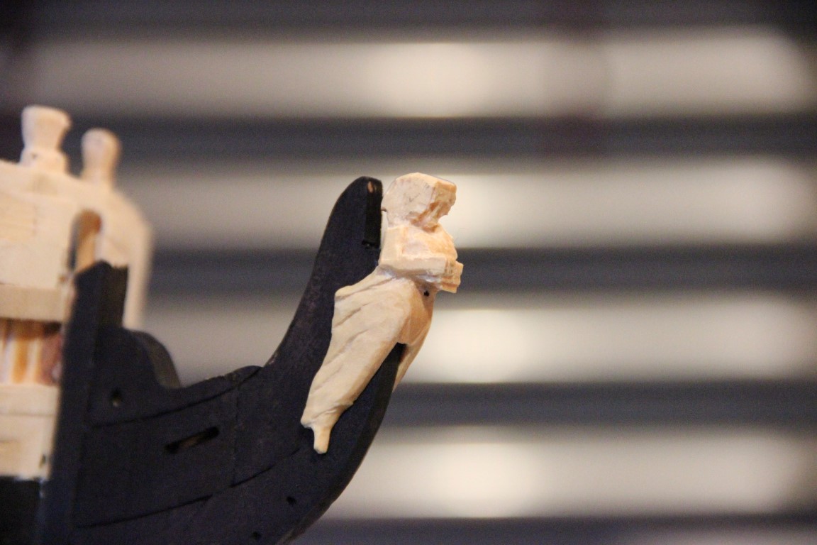
Figurehead:
My first ever attempt at carving in the round. still very much a WIP. Boxwood.
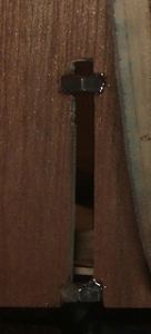
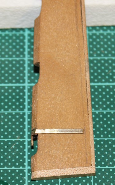
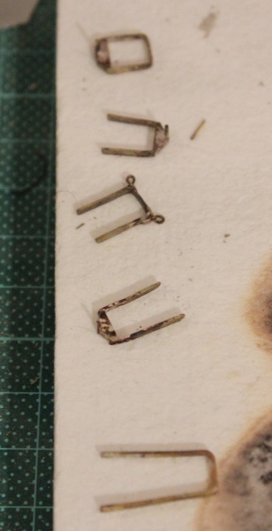
Rudder:
Anyone paying attention to earlier full hull shots will be aware that the rudder is fully coppered. However I have a couple of photos of where I am in the process of doing hardware...

Colin
- Timmo, Blademaster2444, mtaylor and 3 others
-
 6
6
-
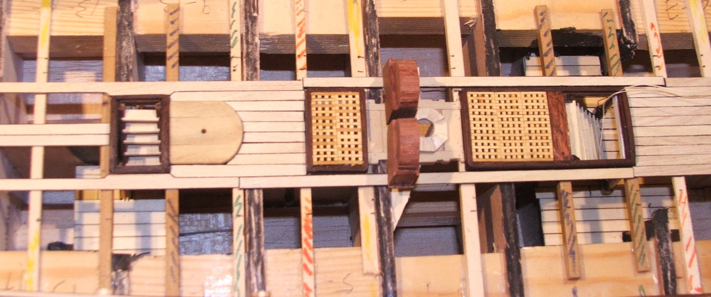
Interior Fit:
While also working on the exterior some of the main deck components have been assembled.
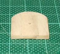
Capstan Step,
I think this was Holly - It's been oiled so looks different in the last photos to the deck planking. It's 3 individual pieces slotted together.
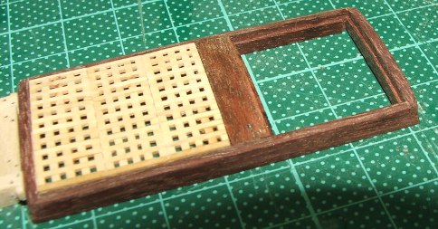
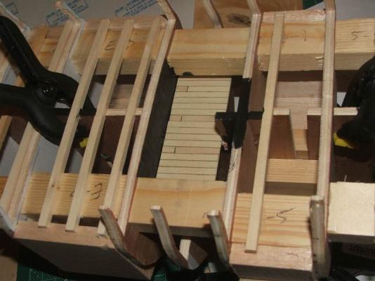
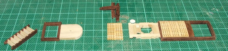
Gratings and Coamings:
Gratings were manufactured from Boxwood, one side notched, with straight pieces glued across the notches. I made larger then cut them down to size. The coamings are of jarrah, beveled, rounded off, cambered, and I used a camber on the inner face to force the gratings to bend a little to reduce the sanding involved in shaping them.
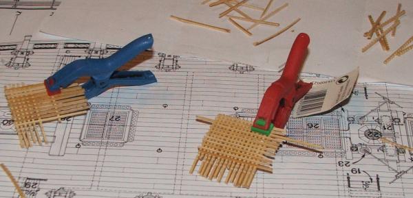
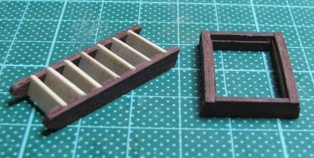
Ladders:
jarrah and holly, coamings made the same way.
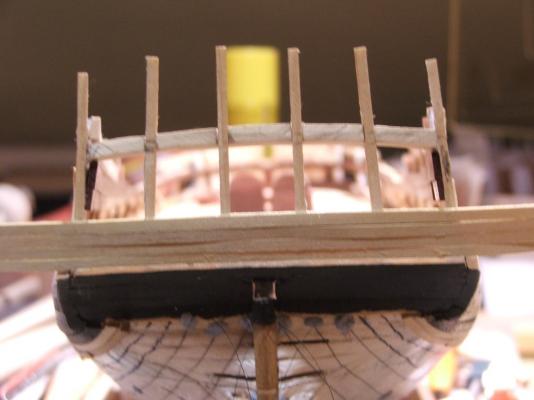
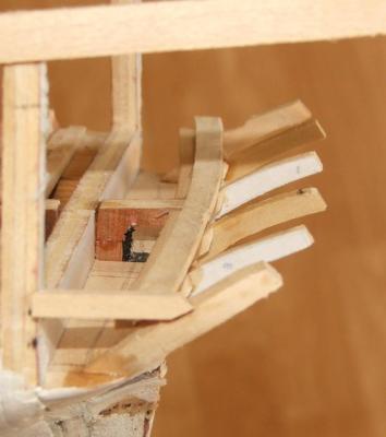
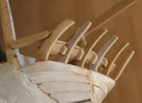
Mainmast partners:
Made from Holly. This was one of the interesting components to build, as the plans disagree on different views. Some views they are notched to allow for the outboard leg of the chainpump to pass by, in other views it clears the partners and no notch is needed. Building the chainpumps showed the latter was correct.
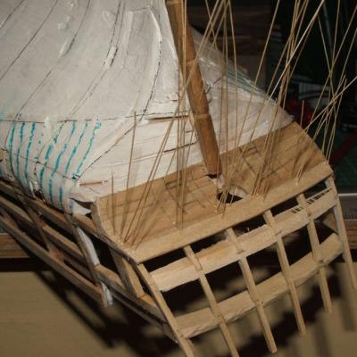
When you put them all together...

You can see also in this the riding bitts have been completed and are in place as well. Deck planking between the structures has started there as well.
Colin
-
Hey Kevin.
I got one of those about 4 months ago for mini painting - loving it. I have no experience with any other decent airbrush, so can't compare.
I am planning to use it on the wooden ship - I don't mind masking stuff, and getting a smooth layer of paint with no brushstrokes seems worth the effort (though I wouldn't spend that money to buy an airbrush just for wooden ships.
Colin
-
Continuing on.
Getting there.
I can't find any pics of the lower hull planking in progress apart from this
 .
.
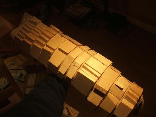
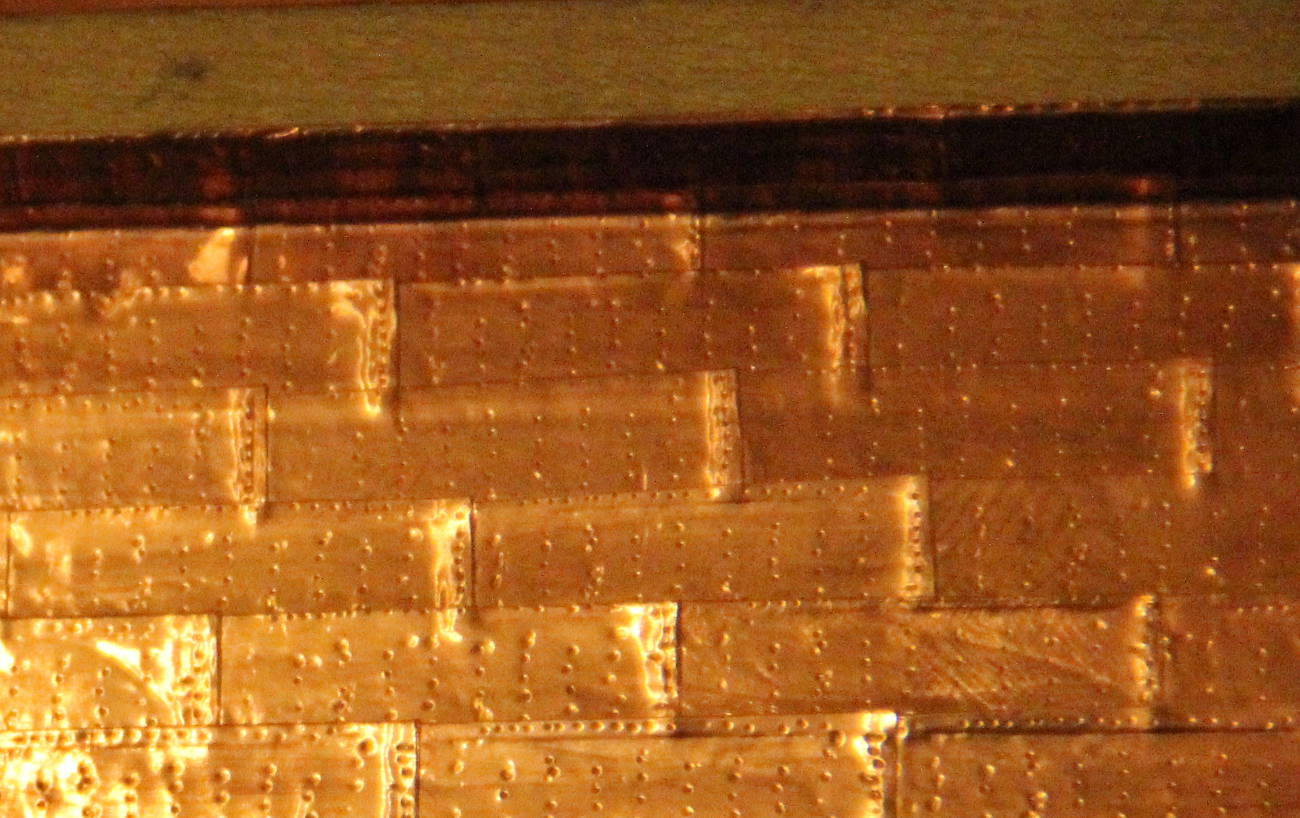
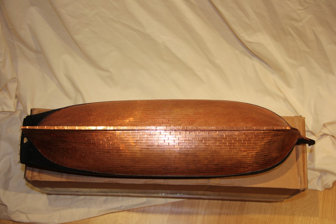
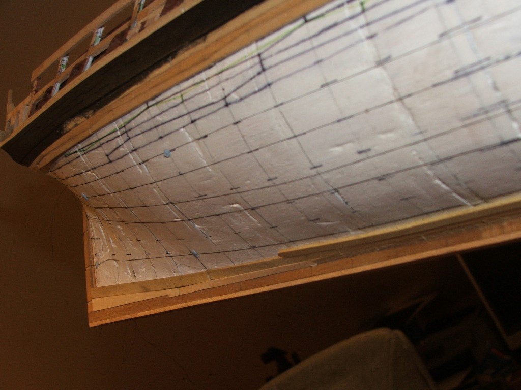
Coppering:
Coppering is done with individual plates, prestamped with a nail pattern. I bought 7/16" (I think) adhesive copper, and cut into 3/4" lengths. I was really pleased to find a width of copper that was exactly right at my scale. For the whole hull I used an entire 32yd roll with about 100 to spare.
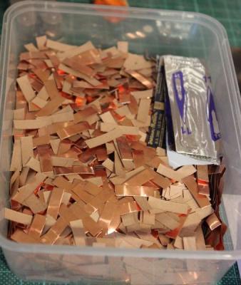
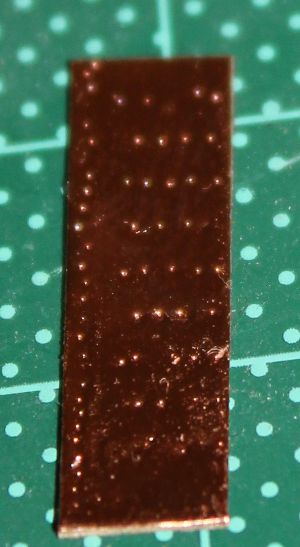
I tried an experiment to get the nail pattern right. I took a 2mm thick peice of strip, glued a nail pattern on and drilled holes in the appropriate place. Then I used acupuncture needles through the holes and on 2 edges. The AP needles are 0.25mm diameter, so are actually pretty close in scale to the nails. The nail pattern I produced was like this...


Pros: good pattern that burnishes down beautifully.
Cons: Fiddly. There are 40 odd needles that need to be in place, even depth, glued down. They are smaller than the smallest holes you can easily drill. They are designed to pierce skin easily. They do blunt, and bend. To make the press easier to hold, I created a handle out of scuply around the rear side of the needles.
I got delayed in coppering so the first few plates went on about 6mo before the rest. I decided to take a pic to show people what you can expect from copper that has been handled, and exposed to air.
Progress....
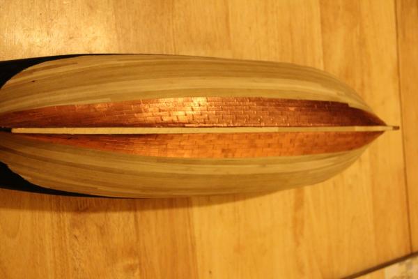


Just visible in the last pic is the batten along the top edge of the copper.
Colin
-
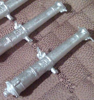
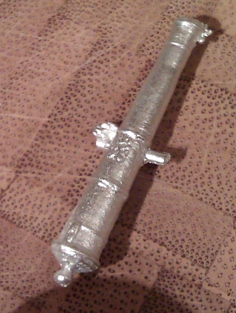
Here's a cannon I cast in white metal (tin with a couple of alloys to improve flow). These are straight out of the mold, 1/64 scale 6 pdr.
Your issue with casting metals is finding RTV rubber that can resist the heat. Most RTV rubbers that you find have heat resistance in the low 200deg C. Brass/ Bronze melts at over 700C so you'll need to be using lost wax and other mold material (look at jewlery casting). White metal melts just over 300C. Your lead alloys melt lower and flow well, but as mentioned they have downsides.
The upside of metal casting is "fails" go back in the melting pot. Resin casts that fail are wasted material.
Colin
-
Taking a small step back - some of the photo's I found on the work computer show I've missed a couple of things
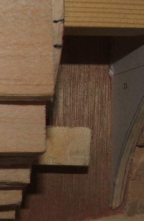
Internal Hull:
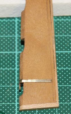
Mast blocks are glued on either side of the keel at the base of the mast slots. This creates a 6mm wide rectangular slot that is narrower than the mast at this point - this will allow the masts to lock in and prevent twisting.
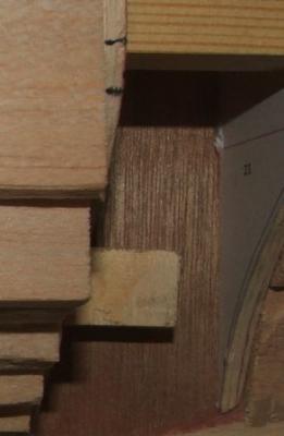
Capture nuts installed. Screwed on to the bolt (to make sure the thread spacing was right), slotted in and epoxied. one at the top of the slot and one at the bottom. Should be very solid.
In cutting the center keel I had marked all the points of deck beams and notched the ply to accept these. I've then installed all the deck beams in appropriate places. This will allow me to plank the deck and have the plank ends on beams.
A small section of decking of the lower deck was done to make sure if anyone could see down the main companionway that they would see deck. THis was later made a bit larger.
You can also see there the spacers I used between the frames. These both help with squaring the frames and stiffening the hull during early construction.
-
Thanks Guys
I've found a few more pics so have updated a couple of existing posts to show a little more...
Colin
-
Hey Gary;
Guy pendants are considered part of the standing rigging, but they then have "falls" that would be used to tighten them.
From Steel
GUY-PENDENTS are put over the jib-boom, the same as the horses, and the inner ends reeve through a thimble, on the quarters of the spritsail-yard, and turn into the strap of a double block, with a throat and round seizings, which is connected, by its fall, to a single block, that hooks to an eye-bolt, near the cat-head, and leads in upon the fore-castle.
Falls are usually tan in shipmodeling as that line is running through blocks, and the Pendants themselves could be black with no arguments.
I haven't looked at rigging recently, but the run of them provides 2 functions - stabilisation, and helping haul the jib inboard when needed.
For sloops of 14 to 16 Guns Steel lists 2 singles (no double block as in larger ships) and gives 10" block for pendant, and 8" for the single.
Colin
-
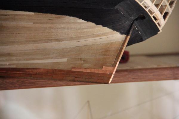
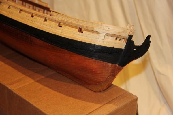
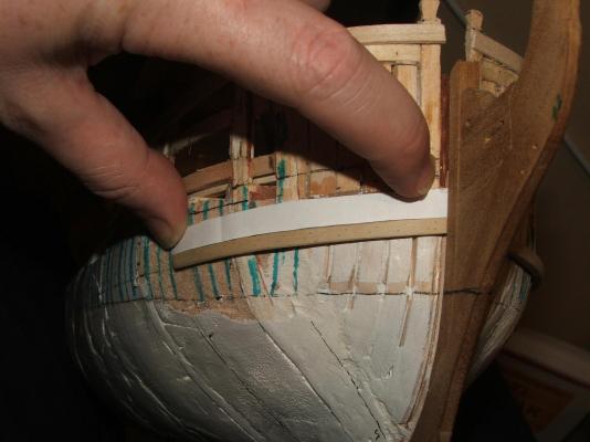
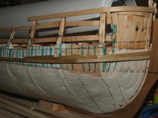
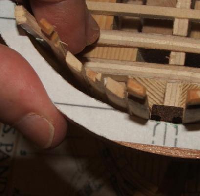
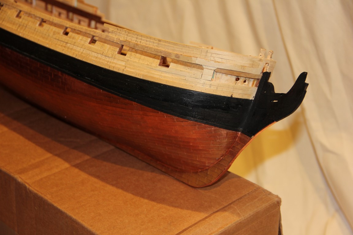
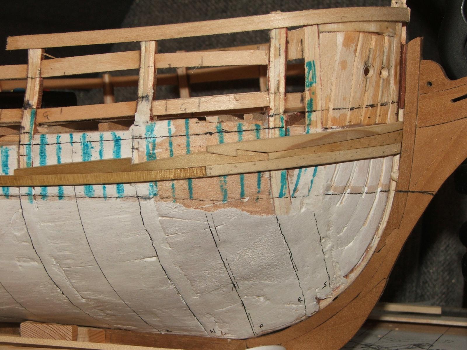
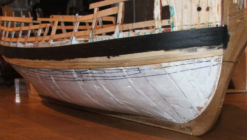
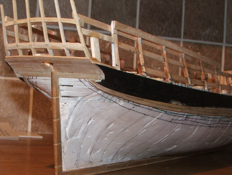
In the above you can see the planning for the diminishing strakes. They were top and butt, and decreasing thickness from nearly wale thickness to the thickness of the bottom planking.
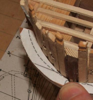
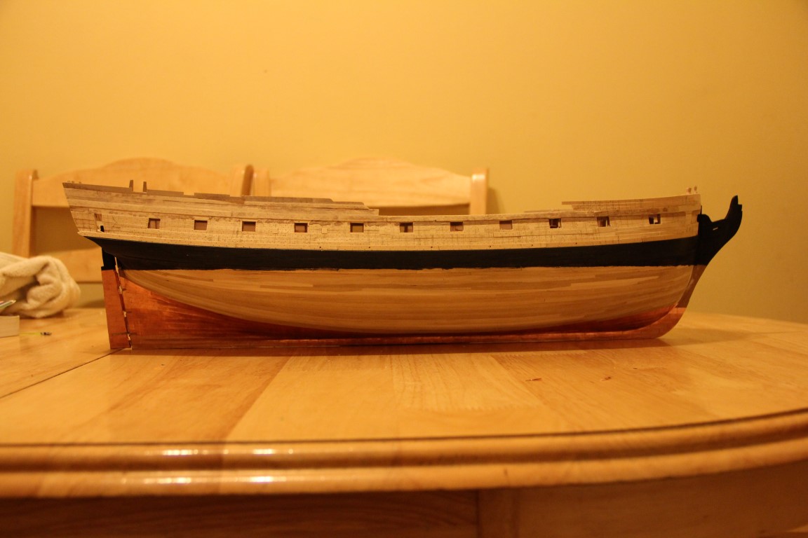
The rest of the planking was planned out with thread. (pics are brutal but.....)

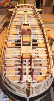
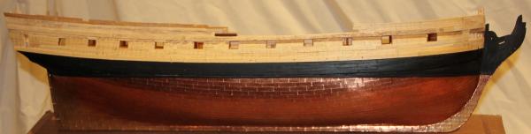
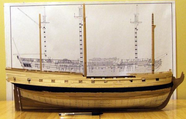
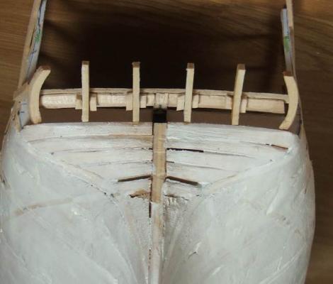
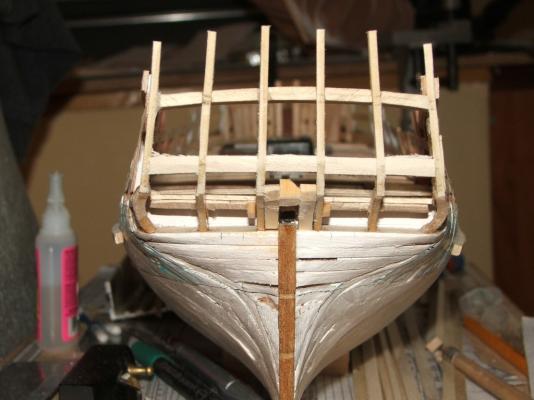
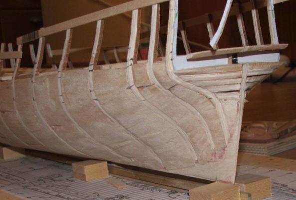
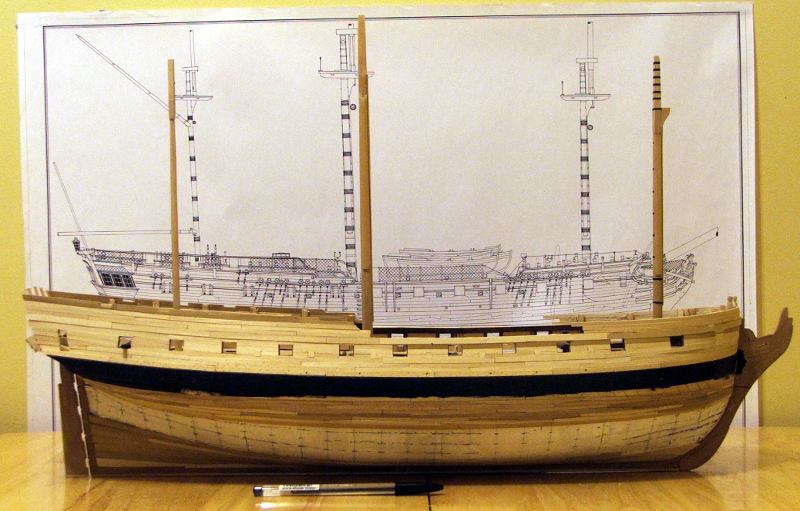
Here's a side profile about halfway through planking. I've planked up the side of the hull as well as down. Planks vary in thickness according to which planks they are and where on the hull they fall.
Masts are there to make sure (while I can still get inside that the chocks and partners are in line and straight. there will be a separate post for making these later)

- AntonyUK, gjdale, michael mott and 7 others
-
10
-
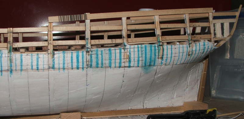
Planking
On the hull were marked the waterline, stations, and position of the wales. Positions of the frames were marked in as well - here the spaces between the frames is in blue. This is where having a full solid hull was helpful. Also timbers marking the top and bottom of the gunports were added. This was the right way to do things. I later changed my mind and tried to do something different that just ended up being fiddly and way more work.

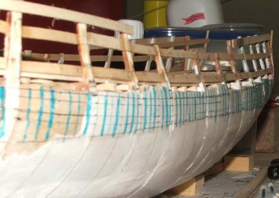
Then the wales. 3mm thick Tulip. McKay shows hooked scarfs - so hooked scarfs it is. Marking in "frame" positions allows trenails to be correctly positioned, and makes sure that the planks finish in the correct place.

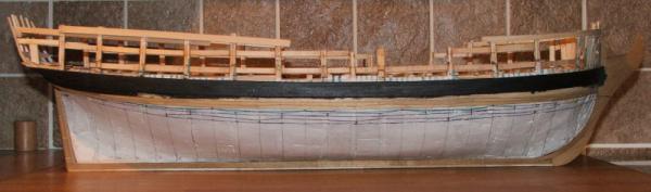
progressing to...


- mtaylor and Elmer Cornish
-
2
-
thanks Sailor
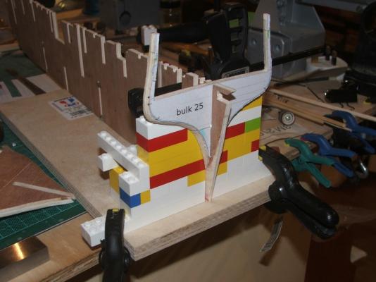
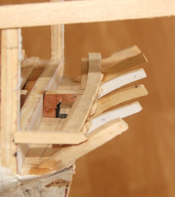
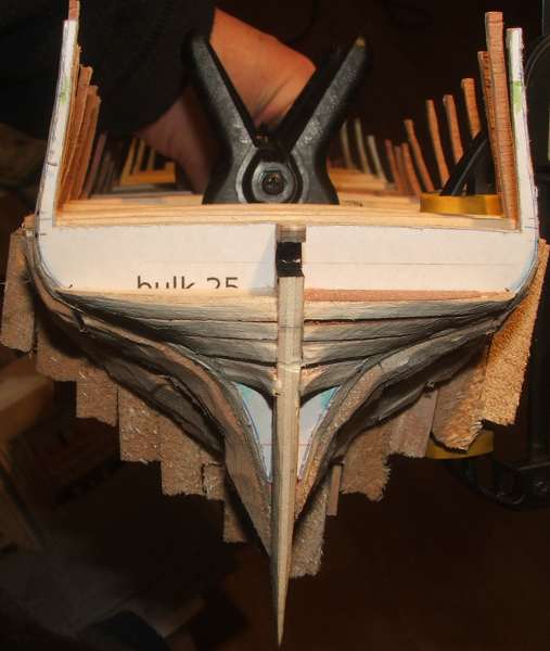
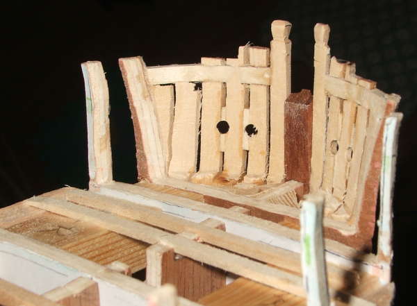
Framing the stern:
Much like the hawse timbers at the front of the hull, I made some Transom pieces at the stern, using the shape from the drawings, but only using the external shape and having them butt up against bulkhead 25. The wing transom then had it's top surface curved to mach the plans. From there the timbers that make up the rest of the stern were constructed essentially the same way as POF construction, but in some places not being as careful since it was going to be fully planked over. Getting the spacing right for the top of the frames meant making the QD transom at this stage as well. I was well happy with that part. Framing is basswood; lower transoms, ply; QD transom holly; counter planking tulip.
Some pics of the lower counter timbers
Fully built...
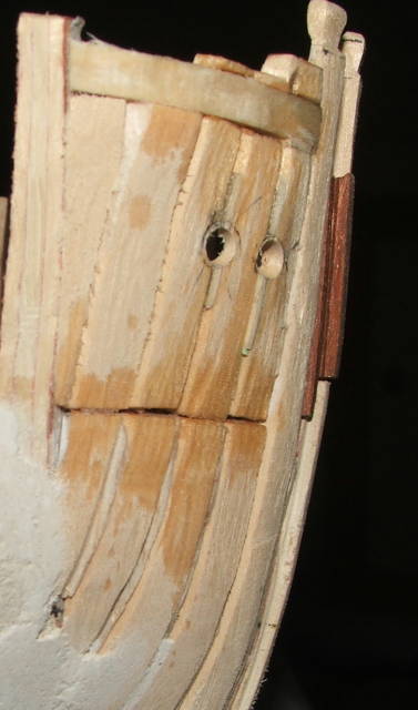
Planking for the lower counter, including trenails.
-
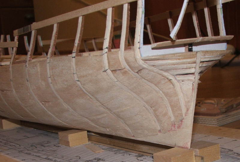
As I came to fair the hull I was struck by some of the solid hull builds that the Russians use.
I packed between the bulkheads below deck level with balsa, and sanded the whole hull. This helped with the process of fairing as the shape was more obvious and getting a smooth run was easier.
It took much longer to sand than balsa would suggest.
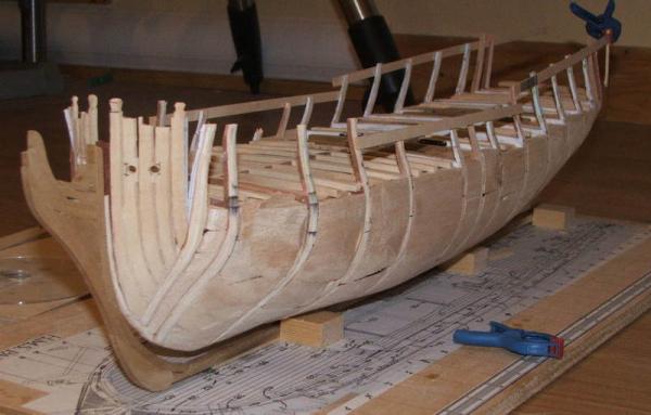
Here is the stern during the process - balsa crudely shaped with the dremel, and the transoms having been shaped.

This was then sealed with several coats of dilute white glue with a small amount of white acrylic paint in it resulting in a smooth very hard surface, and easy to draw on as you'll notice in later posts.
That's it for tonight. Tomorrow stern framing, and on to planking.
Colin
- mtaylor and Elmer Cornish
-
2
-
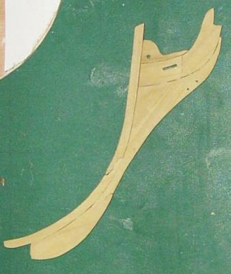
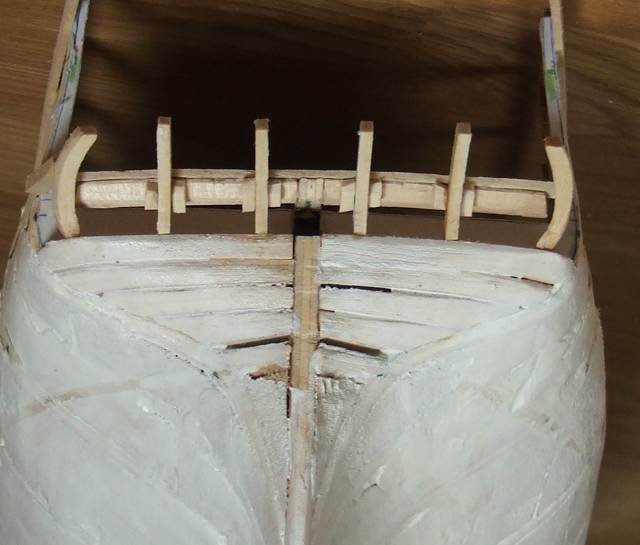
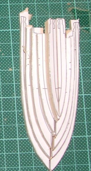
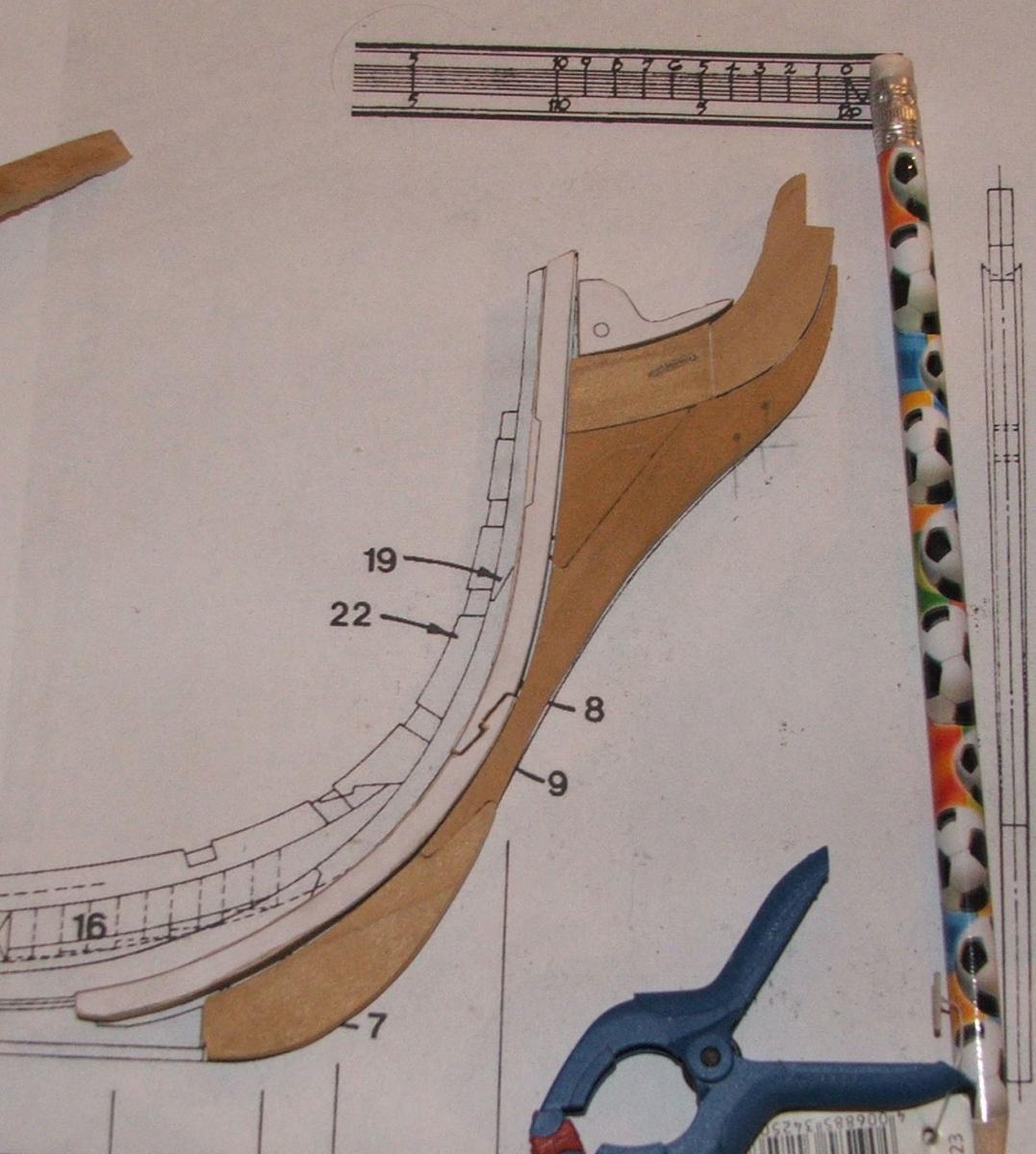
Hawse Timbers:
In order to have a better idea of the correct shape at the bow and better surface for planking I created some pseudo hawse timbers. These were initially taken straight off the side profile of the framing plan, but that didn't create the right shape, so they were redone from the sheer profile lines.
They are "pseudo" as they attach to the forwardmost bulkhead and run parallel to the centreline unlike real hawse timbers.

This is not right.....
Better....
The result


- Elmer Cornish and mtaylor
-
2
-
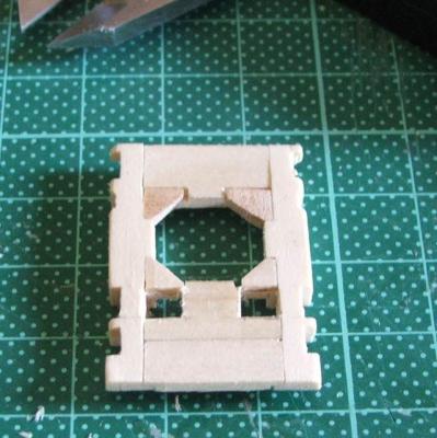
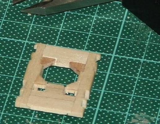
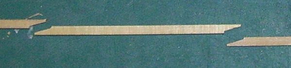
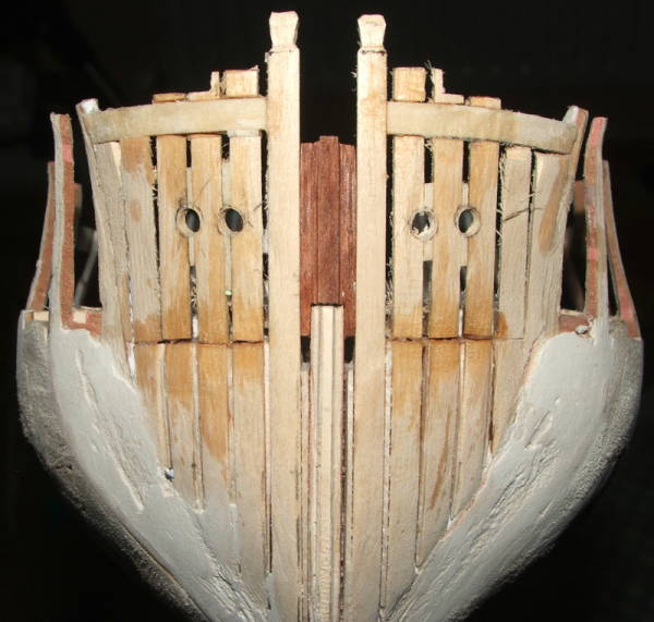
The Head:
Unlike a kit I decided to construct the head and keel from individual parts. All 6mm Tulip, and the usual jigsaw of parts to put together!


- MEDDO, mtaylor and Elmer Cornish
-
3
-
Greg - indeed, someday I hope to build something like that. No time or more importantly to the admiral - no space.
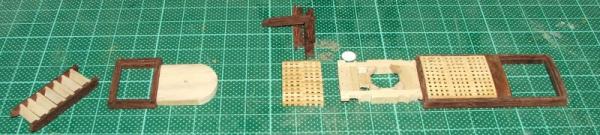
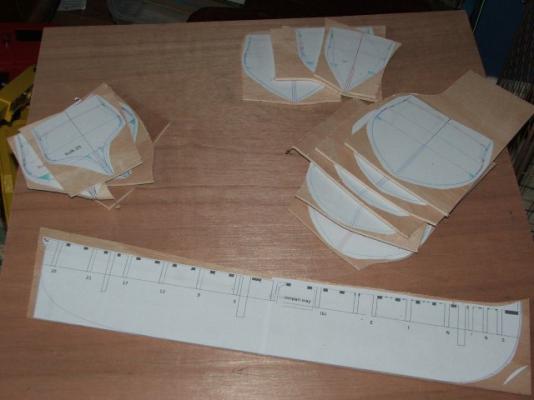
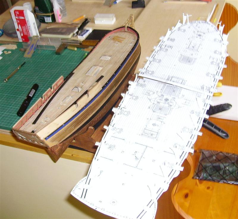
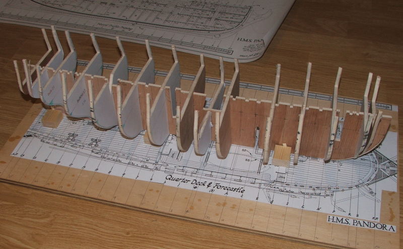
Pre-planning:
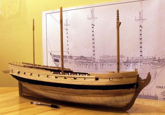
I had started thinking about this build well before finishing the prior model. I pre-printed all the basic structure at scale to make sure it fit together and to get an idea of the final scale. She's bigger than Bounty.
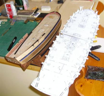
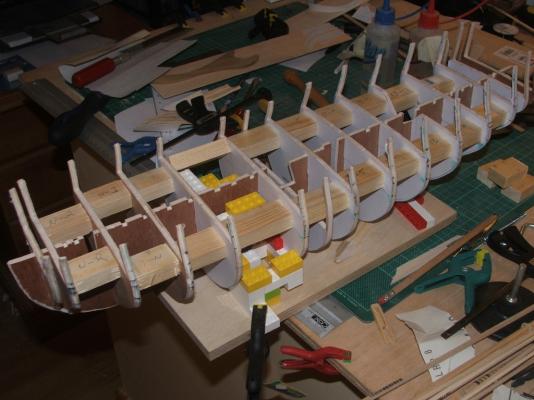
Starting the Hull:
I printed the parts of the hull onto full page sticky lables, stuck these to the ply, and started cutting.
After which it was a fairly standard POB construction process. The slot in the bottom of the centre keel is for a bolt later to fix her onto her stand.

- mtaylor and Elmer Cornish
-
2
-
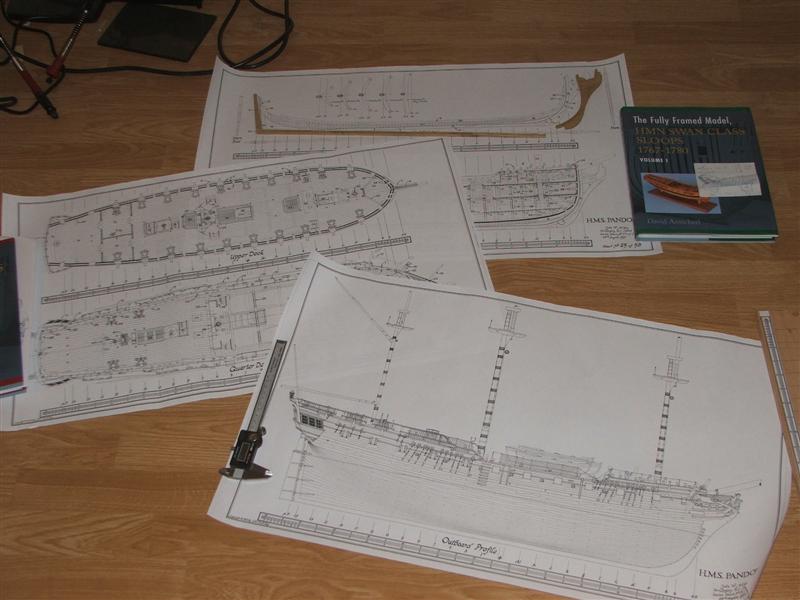
Plans:
John McKay in his introduction to AotS Pandora lists the plans he used - a selection of the original plans from through the Pelican class. Since he has done most of the work I wansn't interested in re-inventing the wheel.
He offers full scale versions of the plans that are in his books, and while these aren't cheap, they are useful. I ordered sheer plans, deck plans, a couple of the rigging plans that are hard to read in the book in my 1/64 (3/16" scale for the Americans).

Pandora Plans - Information Sheet.pdf This is the information that McKay sent. Note that this is 2008 details, but it'll be useful for anyone looking to get plans from Mr McKay. He's a decent guy and all my contacts with him have been useful.
As was pointed out to me - there are some errors in the plans. Some are editorial (wrong scale on the drawing of an anchor iirc), but a couple of drawings don't match (around mast partners) for example. Close attention usually catches these. It was also suggested that the straight run deck planking was probably incorrect (with which I am in agreement), and there was also a comment about something in the guns that would be wrong for 1779, but ok for 1790.
Wood:
Centre keel and bulkheads: 6mm ply.
Hull: I got some tulipwood planks and blanks made up. These have the dual blessing of being easy to work and cheap (I didn't want to throw expensive wood at a first scratch build. Tulip can be a bit green, which turns brown with exposure to light. But given the hull is almost all painted or coppered the visuals there aren't an issue.
Deck: I changed wood options there to holly, not the beautiful pure white expensive wood that Hobbymill does, but a very light grey that looks like weathered deck.
Interior planking and fittings: Jarrah. sigh. done for reasons of the heart rather than the head. Beautiful red wood, but dense and hard, and doesn't bend well. If you think you might want to use it - do a table, not a ship.
Masts: Lemonwood. I love lemonwood - works beautifully, but it aint cheap.
-
This build log will trace my scratch build of HMS Pandora in her 1790 configuration. Build started about 2009 and was initially documented on the original MSW. I'll recreate the log as best as possible, but my memory and not having all the photos to hand mean that the initial part will be not as in depth as the original. It'll probably take week or so to catch up. If you have any questions in the meantime ask - I may be a bit fuzzy on details, but should be able to answer.
The Choice:
Pandora was chosen as a successor build to HMB Bounty that I completed about 2009. I wanted something bigger, military, with a south seas link, existing plans, and since Pandora was historically connected to Bounty it was a logical choice.
History:
HMS Pandora was a 24-gun Porcupine-class sixth-rate ship of the Royal Navy launched in May 1779. She is best known as the ship sent in 1790 to search for the Bounty and the mutineers who had taken her.
Her first service was in the Channel during the 1779 threatened invasion by the combined fleets of France and Spain. She was deployed in North American waters during the American Revolutionary War and saw service as a convoy escort between England and Quebec. She saw successful service as a convoy escort, but the end of the American war the Admiralty placed her in ordinary at Chatham (1783).
Pandora ordered to be brought back into service in June 1790 when war between England and Spain seemed likely due to the Nootka Controversy. However, in early August 1790, 5 months after learning of the mutiny on HMS Bounty,it was decided to despatch her to recover the Bounty, capture the mutineers, and return them to England for trial. She was refitted, and sailed from Portsmouth on 7 November 1790, commanded by Captain Edward Edwards and manned by a crew of 134 men.
Fourteen mutineers were recaptured on Tahiti, but 3 months searching the islands of the south pacific failed to find the Bounty and remaining mutineers. She turned for home, but in attempting to navigate the Great Barrier reef she ran aground on 29th August 1791, and sank the next morning with the loss of 31 crew and prisoners. She remains in about 30m of water about 140km east of Cape York.
Build:
The goal is to build a 1/64 scale reproduction of the ship in her 1790 configuration. Archeological findings have shown the guns and carronades with which she was equipped. The scale was chosen to match my previous build of Bounty. I chose to do POB as it is a fairly straightforward way of constructing the hull and I didn't want as a first scratch built to tackle the huge task of figuring out how to frame a hull.
Sources:
The primary source of plans for the build is McKays Anatomy of the Ship: Pandora, with help from Antscherls Swan class books, and my library of 18C ship books.
(pics to follow)
- moreplovac, AntonyUK, freewheelinguy and 1 other
-
4


HMS Pandora 1779 by clloyd - Scale 1/64 - POB - 1790 configuration
in - Build logs for subjects built 1751 - 1800
Posted
This will mark the end of the historical photos - I've pretty much exhausted the supply of what is sitting around on my computer, and brings us mostly up to date.
First a couple of quick catchup photos:
Trial cannon - allowing me to test fit everything.
Current state of the rudder.
Lower Masts:
As mentioned before I chose to make the lower masts at this stage - to ensure that they fit and were straight while I could still get into the bowels of the ship if needed.
The construction process is essentially similar to what is outlined in TFFM:IV, with some allowances for building at 2/3 the scale.
Central spindle
Lemonwood Blanks were cut to length (not the full length on the masts, since mine terminate in the middle of the false keel), and maximum diameter of each mast. On opposing sides, the centreline, cardinal points along the length (deck, quarters, head) and diameters were marked.
These references were used to chisel/plane a taper into the mast...
Then the process was repeated to taper the other two sides. Once all four sides were tapered, then the sides were marked out for octagonals and the mast shaped into an octagonal.
This was then Clamped in a vice (baswood in the jaws to protect and sanded round.
resulting in this....
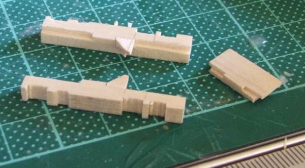
Cheeks
After all that work we then cut a chunk of it away... In full size practice the mast cheeks were shaped around the mast, Hard to do at scale so we cheat by cutting the mast and attaching the cheek to a flat surface.
Marking out the angles through the head and the end point of the cheeks on the mast spindle...
These define the line that we run the mast through the tablesaw (triple check and deep breath time...)
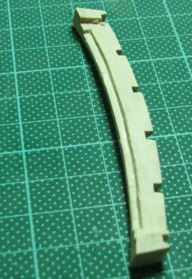
The cheeks themselves are rectangular stock, rounded in the same way as the mast, with trangular notches ready to accept the bibs.
Here is a mast, slimmed down with it's cheeks with bibs attached (with their slight outflare)
When you glue that all together you get this... The bands on the head are paper.