kruginmi
-
Posts
630 -
Joined
-
Last visited
Content Type
Profiles
Forums
Gallery
Events
Everything posted by kruginmi
-
 Hey Gary, Being on the 'Great Lakes' I have befriended a few mariners, particularly one who has sailed his whole life - both small and large wooden craft. He has taken an interest in my hobby and likes to see what I am doing. It was in conversation with him on the steering mechanism that this was discussed. He saw the original rigging leads and through questions had me think through the issues and come up with the correct solution. He was pretty adamant that you would have quite a problem if the ropes were allowed to just slip over the drum (not be affixed), that the tension would be very difficult to remain sufficiently tight under all weather conditions. It certainly sounds plausible. Maybe some of the other mariners on this site can chime in. mark
 -
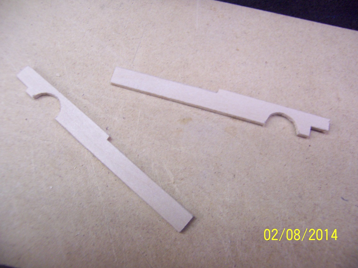
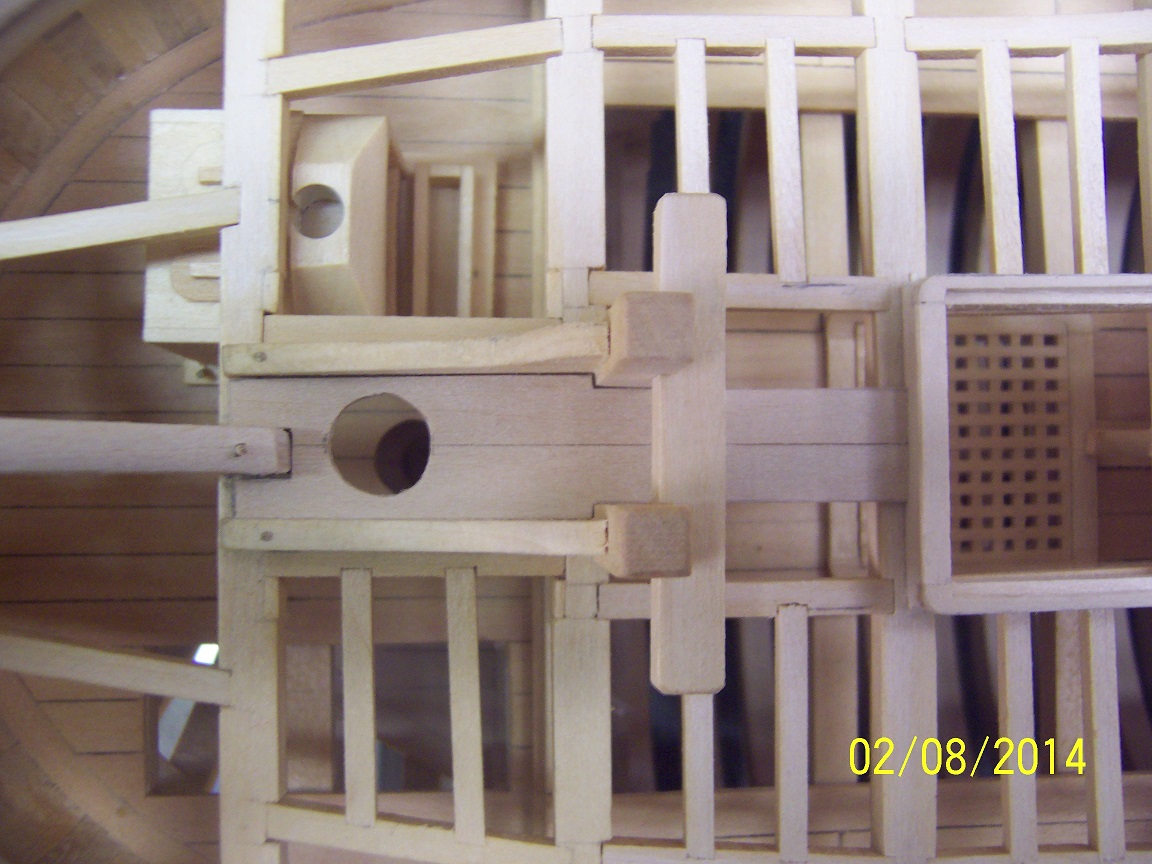
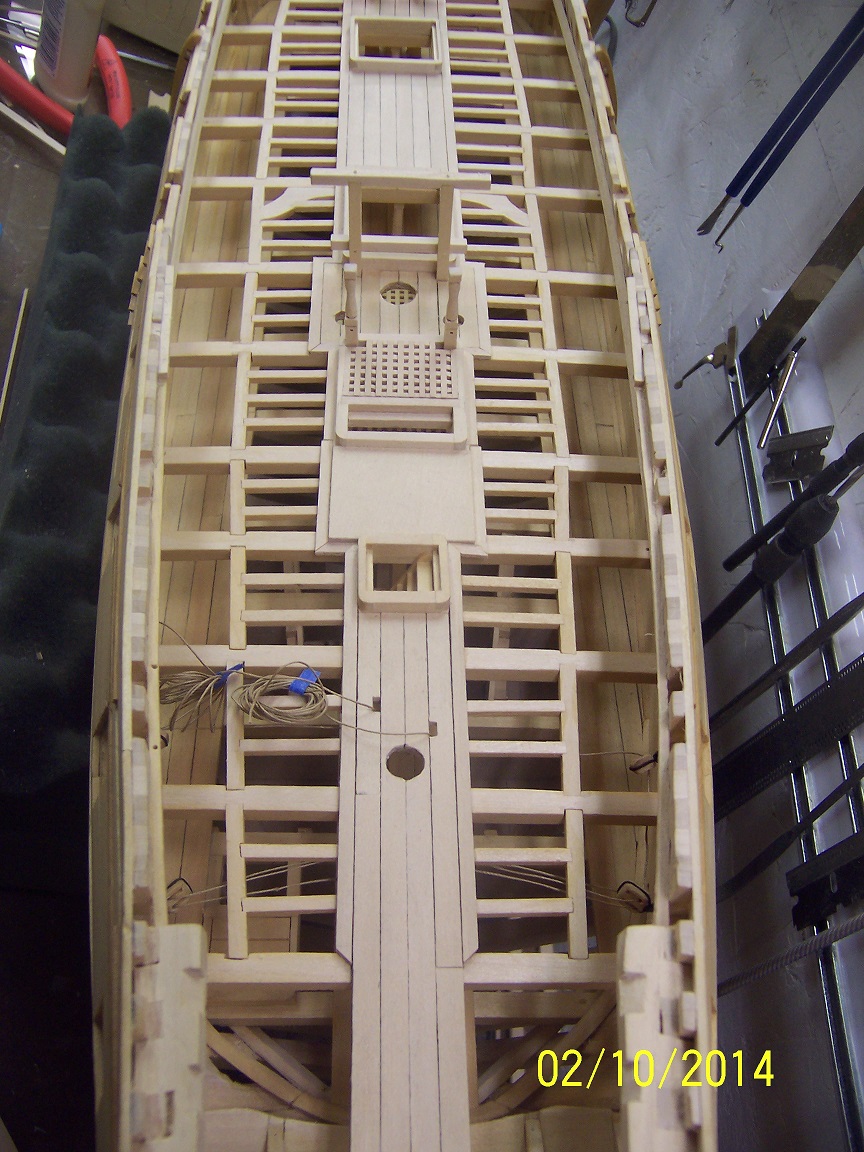
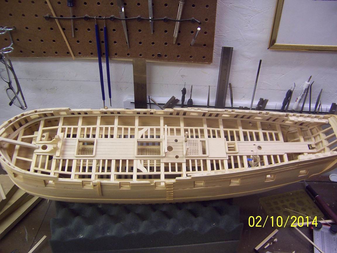
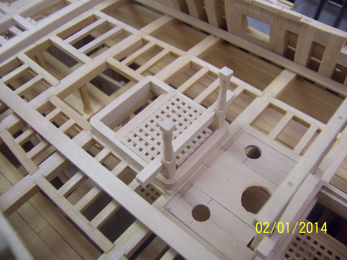
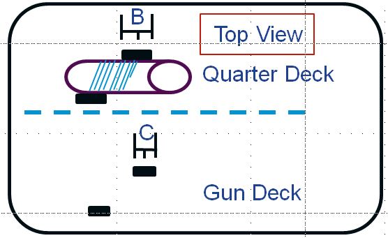
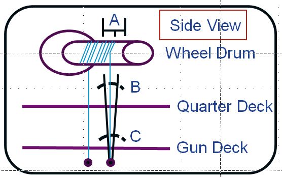
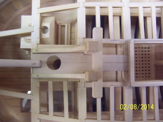
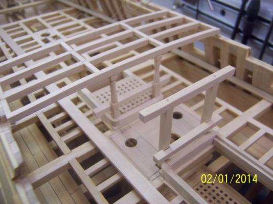
One item I should mention concerns the run of the steering tackle. Without too much thought I had originally 'assumed' the lines went straight up from the tackle below the gun deck to the wheel spool. So....only tubes were needed for where the lines passed through the decks. WRONG. Below is the top view of the setup I finally arrived at: The tackle below the gun deck is at a fixed point (here denoted as the circle below the gun deck). It doesn't move. The rigging as shown travels through two decks to the spool attached to the ships wheel. This spool is not filled with this rigging. There has to be a portion that is clear both at the fore and aft end. Why? Because as the wheel turns the wrapped rigging will move either forward or aft - depending on a turn to port or starboard. So you need to understand how many full turns the wheel needs to turn the rudder in both directions (hopefully the same amount if the rudder is centered). This becomes the distance denoted as 'A' in the diagram. This measurement will be the same for the aft and forward part of the spool. Now if you zoom back out to the full diagram, the rigging will form a V with the bottom vertex at the fixed point as it moves through its total rudder allowance. It is now seen that at the deck pass through points more than just a hole in the deck is required. Looking at a simplified top view: You can see that slits are actually required to allow this full rotation (equal to defined distances 'B' and 'C'. This is larger at the top given a larger distance from the fixed point. The gun deck slit will also need to be boxed on the Druid given it is the main deck and often wet. Additionally, I had thought this rigging on original ships was one continuous line. However, I am told the wrapping on the spool is not always tight enough given the sea state and tension leading to potential slips. So, the lines were usually brought up independently and affixed to the spool at the center point to insure this does not occur. Such much information once taken for granted to relearn! mark
-
Thanks for stopping in and taking a look! On to the gun deck planking! Unlike most of the berth deck there are all sorts of items poking through the deck requiring special consideration and thought. As an example the following (and where they fit): For the target plank width I decided one fourth of the width of the coamings would be just right. I do have some liberties here since this ship was originally built in America as a cargo ship before being bought into the British navy. This decision made for some clean lines: After getting these affixed I thought the open sections needed some cleaning up to get good lines for the eye. I decided to go for a trim piece slightly less than half plank size and framed out the opening, using mitered corners at all joins. There is no end grain visible. For clean up I find a scraper (usually a straight razor blade) works best. A few swipes and everything looks clean. Now on to the deck sides. mark

-
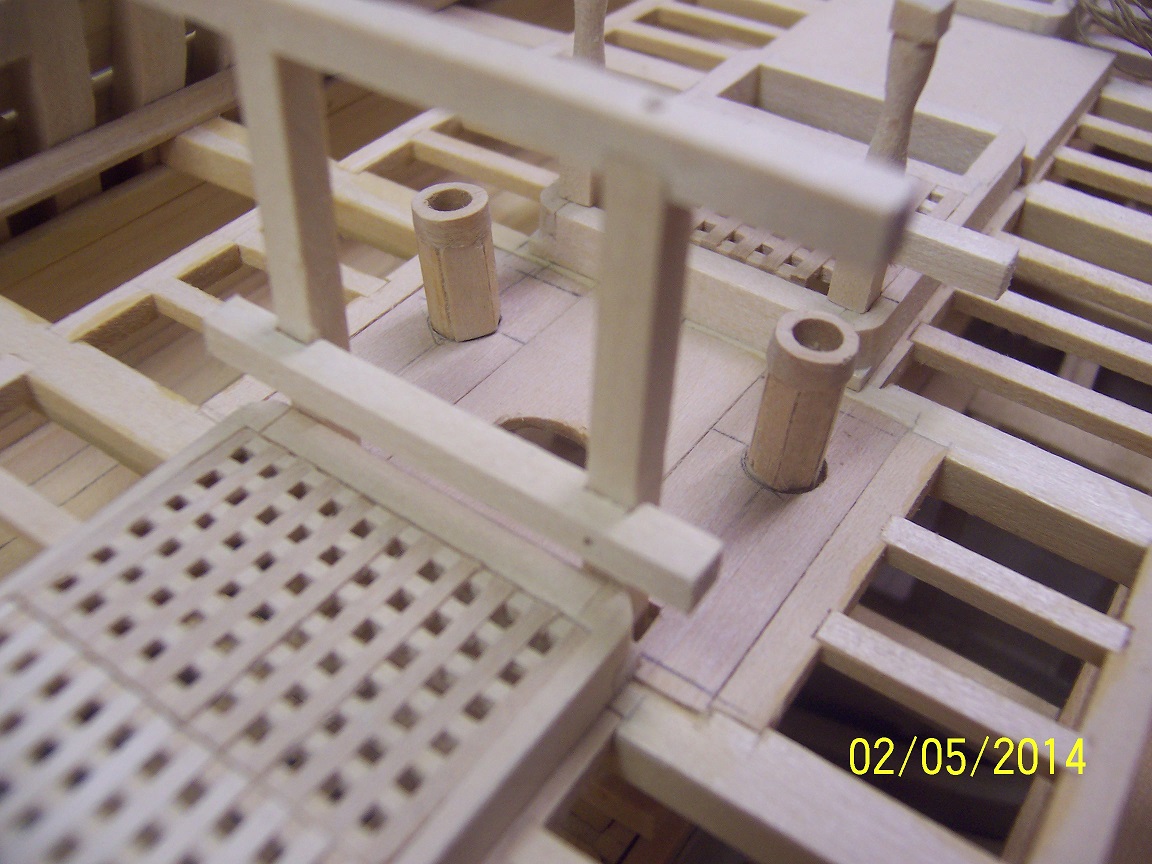
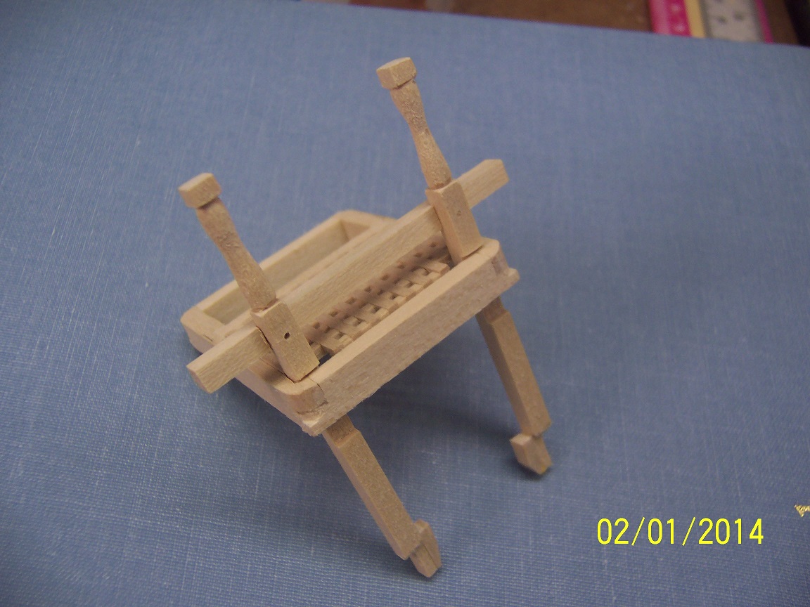
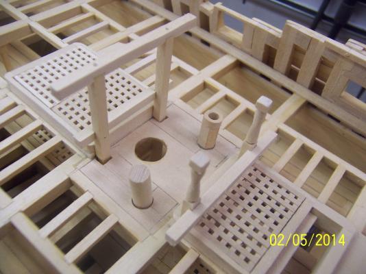
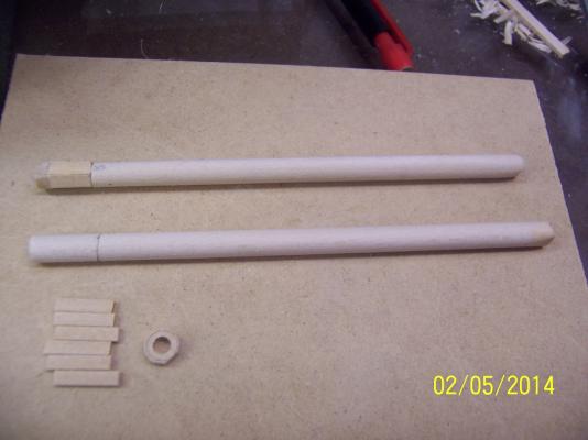
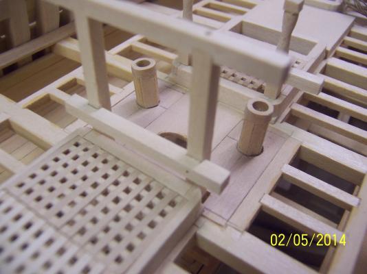
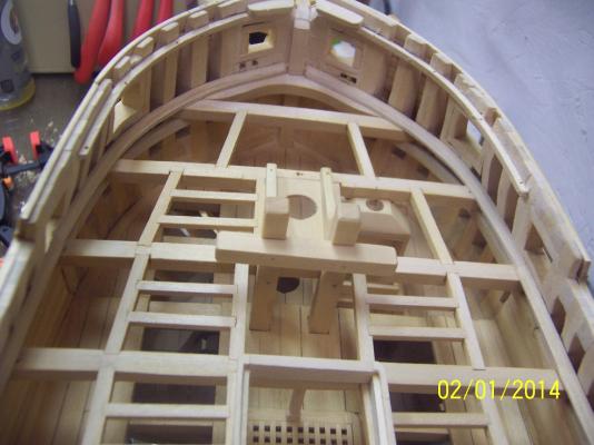
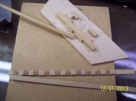
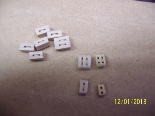
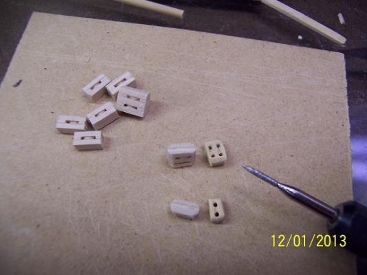
Success breeds progress. Tonight was to climb the mountain.that I had thought about for a long time - the pumps. I had lathed out rods to represent the pumps a LONG time ago (in a galaxy / home far - far away). Ever since then I had known that I wanted to improve their look above the deck where they were most visible. That decision had churned in my brain ever since, growing larger and larger in mythical proportions of complexity. Today was the day, they had to be done. The following shows a before and after shot (hopefully you can tell the bottom pump is the before): As is usually the case, the reality wasn't that bad at all. After marking where the pumps came through the deck, that line was scribed with a knife and the rod paired down. I used a draftsman guide of six sided shapes to find the appropriate size that I wanted. Wood was cut to these dimensions and I eyeballed the necessary bevel at the edges. These were then glued together and onto the rod. I used piece of boxwood for a cap. The actual handle will be generated later. Tomorrow the gun deck planking begins. mark
-
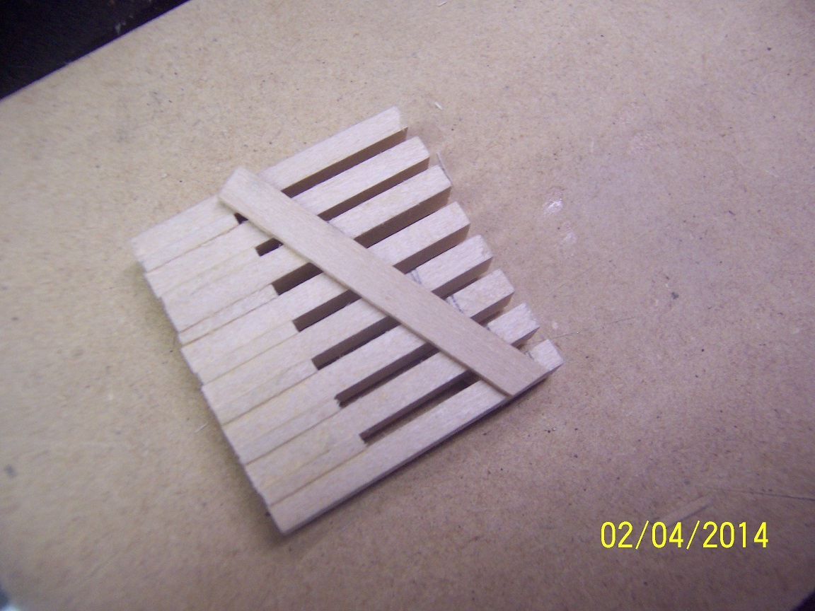
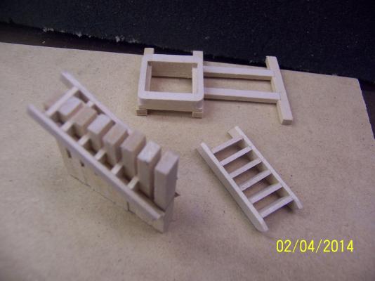
Harvey, With the jig I can make a ladder in less than 5 minutes. As a side note I did put that guide piece on both sides of the jig to avoid tilting the treads as they glue up. I also only tacked the guide pieces at the top and bottom to keep the very slight flex to hold each tread. I am quite happy with that creation. mark
-
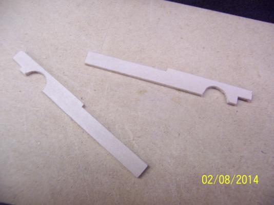
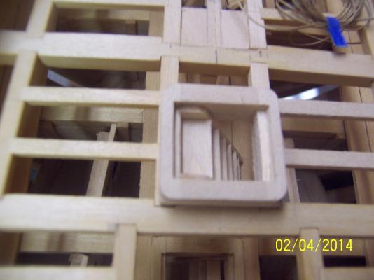
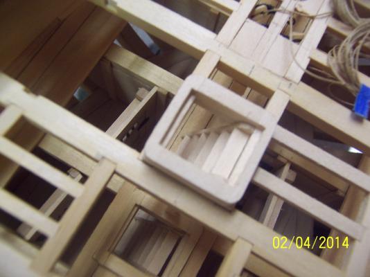
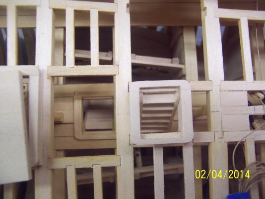
Making some headway, the last connection to the berth deck was the ladder. I decided a jig was necessary and I came up with below: The length of the gaps allowed some tension to be available to hold the treads while the sides are applied. I first measured the tread depth from the plan unfortunately from the stairs from the gun / main deck to the quarter deck. After putting the stairs in place it was pretty obvious this didn't leave a lot of room for sailors to make it through the coaming! Upon further investigation I found a view off to the side that showed a much skinnier tread. The jig now paid off since it was just five minutes before I had a replacement made. The result was much more viable: With the windlass plate off you can see the two sets of stairs from both decks. This will definitely work. As i complete the deck requirements from bow to stern I will very soon be laying the deck planks. Mark

-
Thanks Bugra, Believe it or not 95% of this is basswood, not boxwood. Mark
-
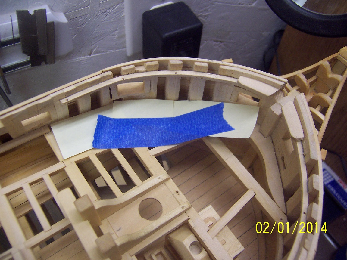
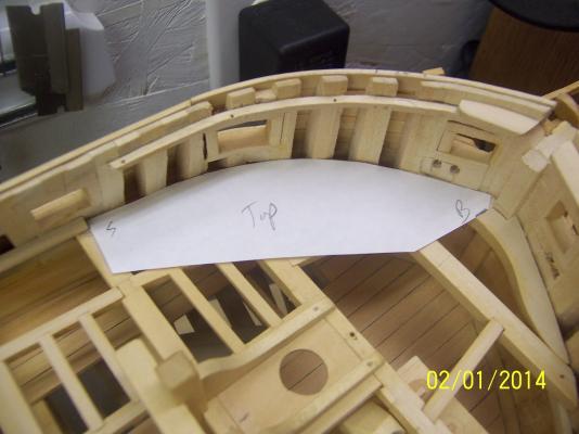
As I move to the gun deck (which is actually visible as the top main deck) everything added really has a big impact. As I work to get the hatch coamings affixed I got one last look at a component that I was particularly proud of. Once it was affixed most of the beauty was hidden but at least I have photographic evidence! The following is the installed view with and without the associated quarterdeck roof. To permanently affix the deck beams I needed to add the waterways. Given the flow of the hull, the waterway from the stern to close to the bow was affixed in one straight piece, slightly bent and glued into place. For the profile, the same scraper was used as the berth deck. For the bow, I used my favorite technique of using post-it notes to get the rough shape, followed by a piece of paper to refine, finally using the correct wood. When the port piece was cut out I was happy to find that by flipping it over it fit just fine in the starboard side. I love it when these things like that happen. Mark Now on actually laying planks (as soon as the stairway coaming is put in).


-
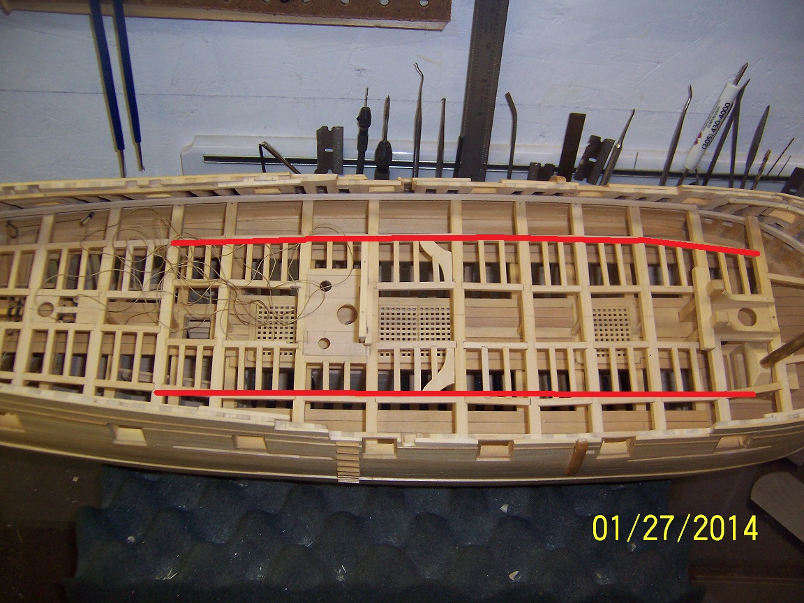
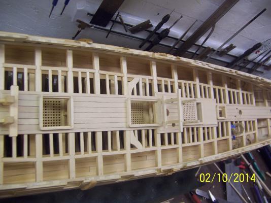
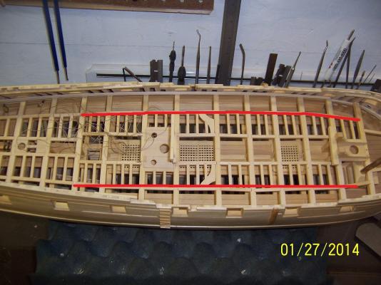
After a bit of a hiatus I finally allocated some time and much to my chagrin the first thing I did was to pick up the hull exerting too much pressure on the rudder and.....snap, the tiller arm broke where it connected to the rudder. I didn't take any pictures so there will be no records of the mishap (hah, hah). Bad news, good news. Bad news was that it broke. Good news is that the area was still entirely accessible. So I took two steps backward and removed the rudder structure. I added a steel pin where the tiller arm met the rudder (brad nail with head clipped off) and after everything checked out reinstalled everything. So, so many hours later I am right back to where I started from. Now to be so very careful in the future anywhere near the rudder! Okay, now to actually make progress. I am making the plan for the gun deck and my original plan was to replicate what I did on the berth deck and use straight planks (as shown with the line on the bottom part of the picture): I cannot claim that I had intent with how I laid out the faux carlings but it certainly looks like the better idea is to plank the outer areas with curved planks that match the flow of the hull (tried to demonstrate with line on the upper part of the picture). Certainly make the time required to implement a lot longer but it will show much better. The central part of the deck will still have the straight planks. Mark
-
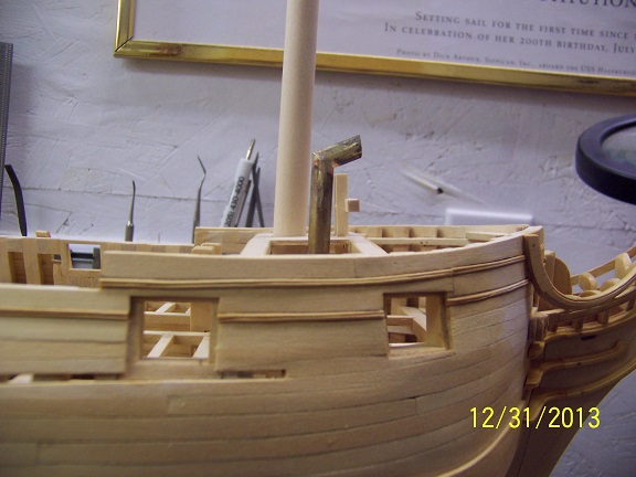
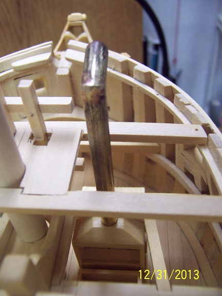
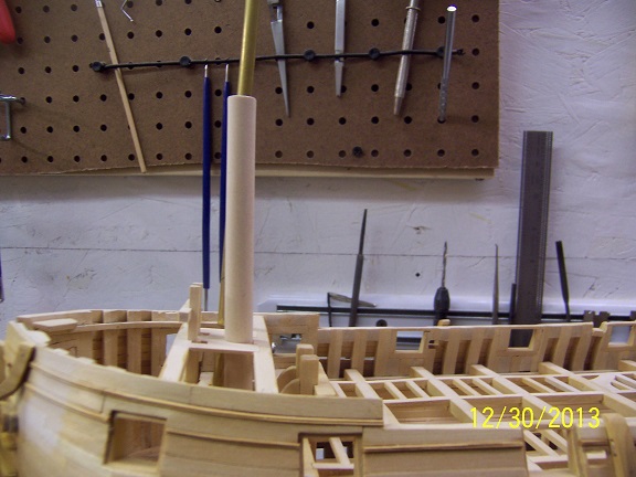
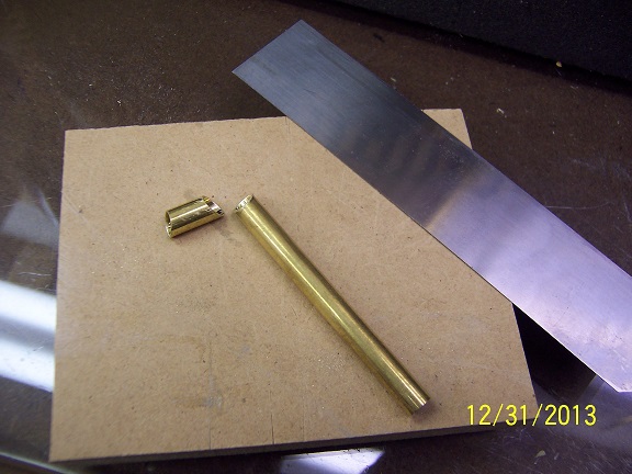
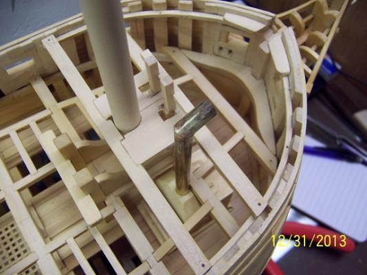
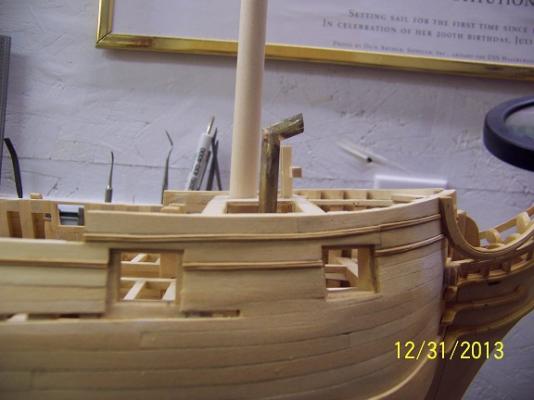
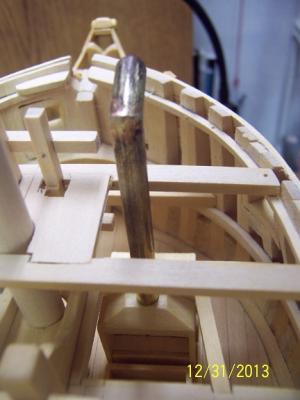
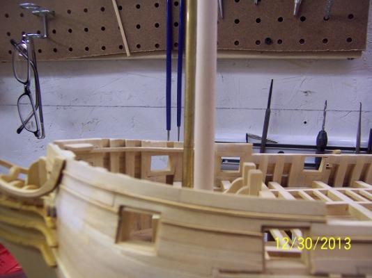
I will skip over the ice storm, providing refuge to a family of 8, car issues, the holidays and such and actually do some modeling on the last day of 2013: The object is the stove stack. Into my stove I had cut a slot for an 1/4" brass tube which I procured locally. Luckily I decided to just put everything in place with this oversized tube 'just to make sure.' Well, it was very obvious the angle was significantly off: Pondering this it all made sense. The stove was sitting on a deck that had a slight pitch up towards the stem. Looking at the plans the base of the stove was indeed angled to allow the stove / pots to sit level with the water line. how many times have I looked at these and never seen that? So I added the appropriate shim and brought the angle to rights: With that taken care of I was able to use the deck beams to mark off the different levels. These checked out with the plans (always a good thing) and I identified the height and angle required which I cut out with a very fine toothed straight saw: After some silver soldering (got so excited I didn't take any pictures) the pipe was complete. A good result for not so much work. It still needs to be blackened but this will wait. I really like the solid feel while still able to remove it out of the way for now. This pipe now sits as Mr. Hahn constructed it. I am still scratching my head if I will go ahead and construct the brass cover assembly. Next job is the berth deck waterway so I can start planking that deck in. Merry Christmas and Happy New Year, mark


-
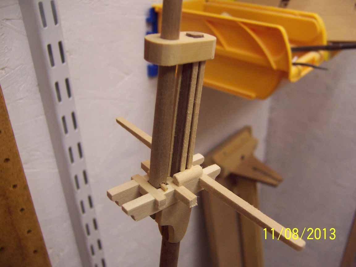
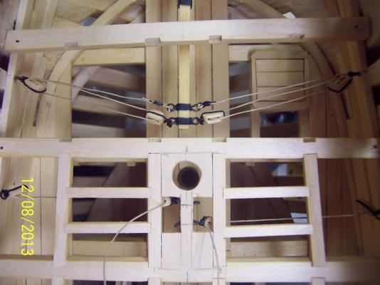
Whew! When I decided to 'knock' out the rudder I had no idea the task I had set myself on. Luckily, I say that looking back! That's right, the rudder is finally in the rear view mirror. This morning I escaped from the family and fashioned the blocks and rigging necessary to get every thing ship shape. A very big day in the life of Druid. I will post a couple pics of the obligatory rigging components. Very tight spaces, small pieces and trying to get everything to match up with the plan. First in the rough with all the stropping added and the synching up required. Now for some clean-up and final looks (before it disappears into the depths of the hull: Finally, I put it all together (looking at the plan MANY times to insure each side was a mirror of the other and corresponded to the plans): Unfortunately, everything starts to disappear as the next level carings and ledges are added: As you can see I did need to cut out a little of the mast centering piece that was in the way, but this is to be all under floor planks. Still need to run everything up to the ships wheel which will provide the needed tension to keep everything a little straighter. I now get to think about this (small) victory for at least the rest of the day, before I move on to the next job. Mark


-
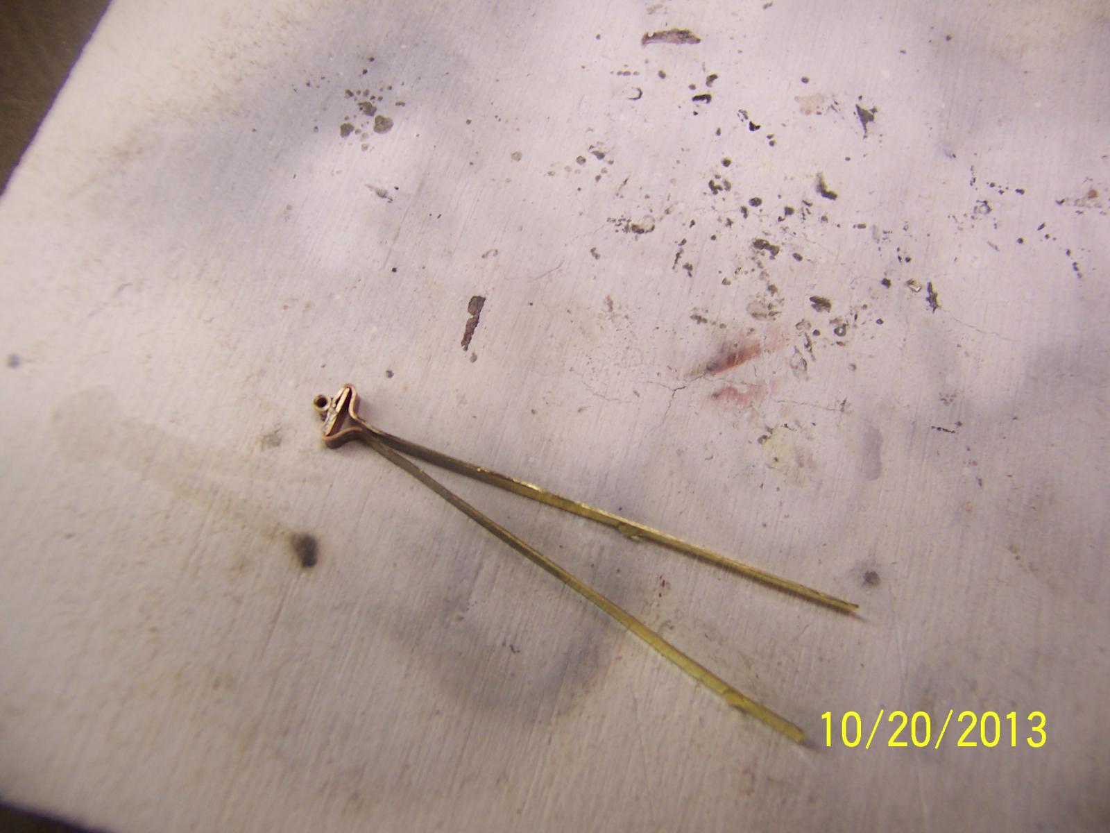
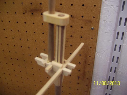
I probably use my proportional divider (just like the one pictured) equal to or more than any other tool at my disposal. I hardly ever use ruler measurements. Anything off of the plan, or for that matter off of the ship being built, is done using these as well as a multitude of other things. I can't tell you how many times I need to find an accurate midpoint or just to transfer a specific dimension from one place to another. Planking has already been stated. With a good pair (mine cost $80) the measurements are spot on. I seem to find more uses as time goes by. Each person has to figure out what works for them, but for me I find these simplify my life greatly - and to a greater accuracy. Mark
-
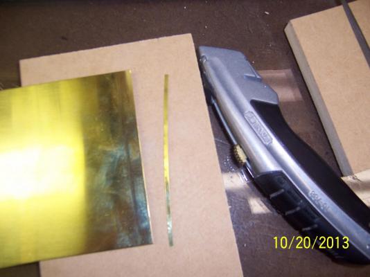
One small addendum, Lou (if you didn't already know): after scoring the brass sheet with the utility knife, I put some straight wood on one side of the score and bent the metal along the score until around a 90 degree bend. After two alternating bends the sheet simply separated at the score line. This resulted in a very clean and straight 'cut' (at least as straight as the score line). I did do a quick once over with a small file to eliminate any sharp edges. Probably better than using scissors (if possible). Looking Great! Mark
-
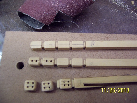
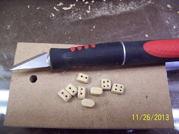
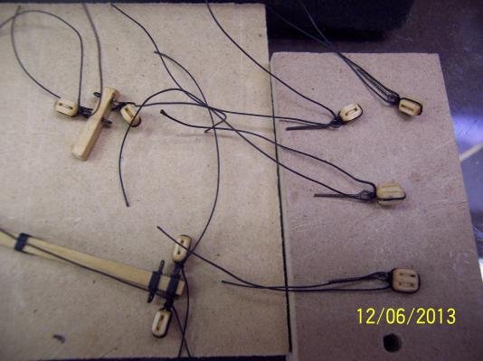
I have had limited time in the shipyard but have been working on those blocks for quite awhile and still not satisfied with the result. They look a whole lot better then above by going on a weight loss plan (width and length). I almost just gave in and went to stropping them when I suddenly realized - this was My Druid. Then it came to me - why make the blocks like kit blocks?? I went and fashioned ones by the numbers in less than an hour (a lot less time than the previous attempt!). Below is a picture of the blocks in mid-construction. I did glue the inner sheave to the block itself. You can see the jig I made up to cut the sheave off of a hardwood dowel. The outer layer is 1/16 inch basswood, the inner one 1/32 inch. Once glued up, I cut each middle layer at the mid-way point. With just a little shaping I compared this with the previous attempt: This is SO much faster than trying to hack out of a solid block (for me) and the result looks so much better. I will still do some shaping to reduce the overall width but that is very straight forward. Each block looks the same and somewhat accurate also. To add the external groove for the stropping to ride in I used a special cutter attachment on my dremel: On any 1:48 scale model (or larger) I will always use this method for blocks. NOW I can finally think about stropping. Mark
-
Sherry, my Druid is 95+% basswood. I experimented with a lot of finishes and ended up using General FInishes Gel Urethane for an even finish without splotches. I showed the results of my experiments in my log. It does add a tinge of yellow that will darken with age. Looks Great - good luck! Mark
-
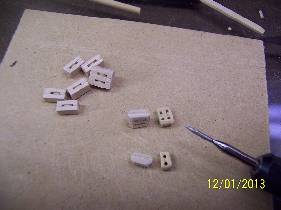
After a bunch of fits and starts I finally tried my hand at some rigging blocks for the tiller. Of course these will not be seen, being buried in the back of the berth deck. I will say the effort for these things is not inconsequential. I think I still have another hour or so of refining individual blocks to bring out their best. With only eight to make I didn't build up any sort of jig. With any more, this would have been a requirement. On the question of stropping I am leaning towards using wire and extending that wire to allow the block to be fixed to the hull. With the tension from the tiller rope they should be very taught and basically parallel to the deck. I am worried using rope a sag will result. Not trying to think too much! mark


-
So, where do they stash the run up here? I like the improvements (though I am a little biased). I need to make friends like you to get such a gift!! They better be worthy. mark
-
Lou, you have pushed my thoughts in a direction that I have been pushing myself (and it sure feels like the right decision so it must be the right one). As soon as you cut the tie with being limited to what is presented, the vistas open up. I will stay with the theme of the British given name and produce a male, hooded Druid (with staff) - a la Aragorn from Lord of the Rings (hah hah). I have a great vision in my mind that I need to capture on some paper and then think about attempting on some wood. I won't get too much more specific (at least for now) so when the eventual blob that looks like an octopus emerges I won't be culpable. Mark
-
Lou - single strip fore AND aft (my guiding principle was it had to look right - and it did to me). Yes, the fid is the little rectangular piece towards the bottom of the top mast. The fid is to lock the topmast into place once it is belayed up from below (it stops the mast from going back down into the seating hole). It is a little bit of trivia you can amaze people with at parties.... Your theme looks great - I just used what I had for the masts, which was a walnut dowel (I think the kit's were heavily warped). Mark
-
Lou, Just a slight nudge in something that is easy to do and I think produces some great results - focusing on the masts. You have done a great job using different wood colors to really make things pop. For my tops I have included the following (still very much in the rough): I put in a fid, a bolster (to alleviate the ratline sharp angle as it goes over the top) and then some strips to allow air between the mast and the ratlines to keeps things dry. Very easy and straight forward and allows continuation of the contrasts you have used so well on the main hull. Your decision of course! mark

-
Thanks everyone, I am liking the new ship profile! By the way, I am taking recommendations for the figurehead. The actual one was not in the plans done by the British. Harold Hahn adopted a women holding a torch since the original name of the ship was 'Brilliant.' This leaves things wide open. I want to come up with an original concept / design and do not feel compelled to do a copy of his beautiful creation (plus I do not want to have to compare my creation directly with his!). I am taking all suggestions into the mix (and cannot be held responsible for my attempt at the chosen theme - hah, hah). This is the only unknown portion of the build left. - Mark
-
Finally on the other side of that rudder. This whole assembly was a whole lot more than I ever thought it was going to be. I will never look at a rudder the same way again! I am pretty proud of the result - kids actually looked up from their IPODS when I went to show them so I will take that as a compliment. At least the three year old was audibly impressed. I can actually think of buttoning up that berth deck now (once I get the tiller arm rigged in, well, once I make the blocks so I can rig the tiller arm in....). Oh well, Here is to the Victories of Today! Mark
-
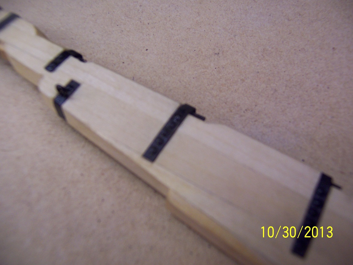
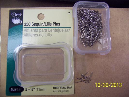
Things you never learn growing up...... I never knew you can buy sewing pins with different sized pin heads! I have been almost stopped on the Druid trying to figure out how to produce all those bolt heads required. I tried a number of things without much success. Finally I just picked up my (almost worn out, threadbare) Hahn book and re-read the Druid chapter. Low and behold, he mentions using pins (as well as touching up the blackened brass with paint). I quickly took the pins I had and knew the head was oversized and not right. The next day I stopped by the local sewing shop and was amazed by the wall of pins. They were sorted by type, metal content and finally - HEAD SIZE! Am I the only one to not know this? I had hoped for brass but after a certain size the only available was nickel plated steel. I hoped it would blacken. I had brought some sample brass strapping and figure out the size 8 head was the correct size. So for $3.50 I had 350 pins. When I got home I plunked one in the blackening solution and it quickly turned black - success! In just an hour or so I had the rudder all bolted in. The next picture is fuzzy but it shows progress where before there was none: All the touching and pushing to get the bolts into their pre-drilled holes (with super-glue) defintely required some touch up (as previously talked about). I used some flat black paint and it looked as good as new. Now that I am over that mental hurdle, this weekend the job is to get the rudder totally mounted to the hull. mark
-
Thanks John and Daniel, I always appreciate the feedback. If this helps, Daniel, that is great. I just know the unknown has always held me back from progress and as I finally delve in (with the help of enthusiasts locally or sites such as this one) the tasks are not as hard as I anticipated. The rudder was one of these things - wood, chemicals and metal all in one package. Here is hoping the next post will show the rudder complete and hanging! Mark
-
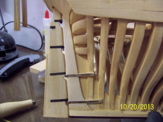
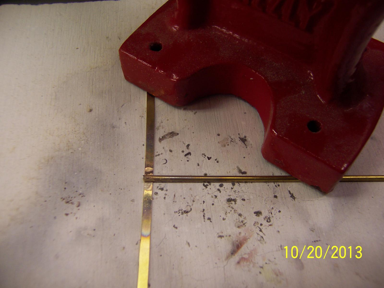
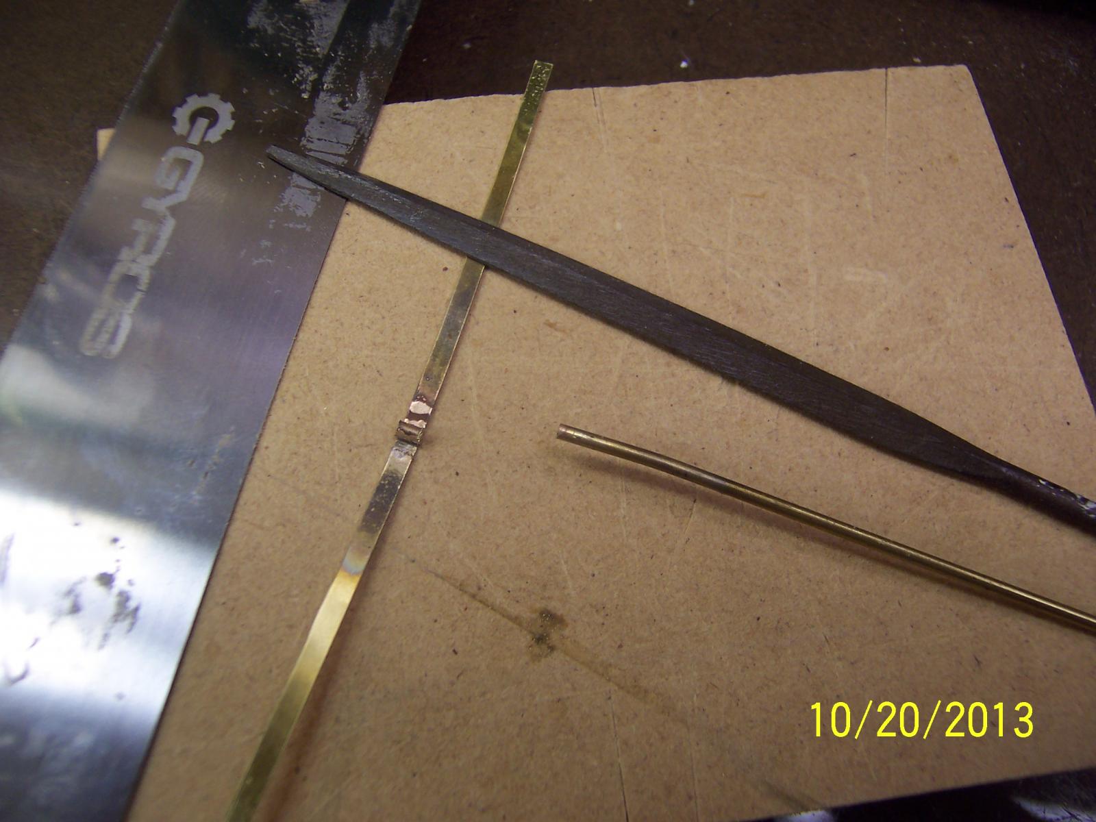
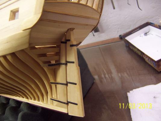
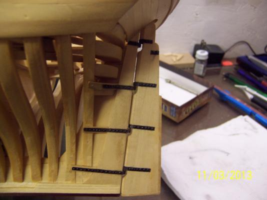
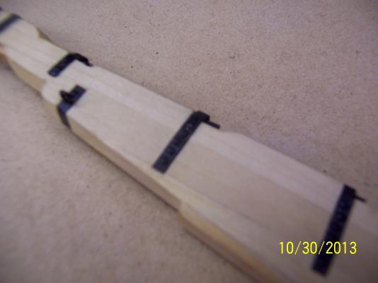
With the time available I am slowly progressing forward. An inventory of my brass supply showed I had insufficient stock for all the work I needed to do (especially when I think about scrap!). I had previously bought it pre-cut but opted to take the dive this time and buy it as a sheet and cut it as needed: Wasn't that bad to score and snap off the strips I need. I will save a little $$ with this and feel my skills have advanced a little. Previously when I worked with the cylinder brass I always inserted the matching rod to hold the tube in place against the strapping. Well, the next two times with silver solder the rod was welded in place as well as the cylinder. As I pondered the imponderables the obvious came to me: do not cut the cylinder to shape until after it is affixed to the strapping: Sample fittings showed that the hull side hinge needed to be offset from the hull more than what the base strapping allowed, so another piece of brass was added. The strapping was bent to hold the new piece firm during heating and soldering, then bent afterwards back to shape. Worked like a charm. With the new pieces attached to their rudder join part, this was put against the hull and the required attachment point was identified. I did mark where the strapping layed against the hull and once again chiseled out that area for added strength and accurate positioning. I decided to add the wood under the straps where the planking was absent. The final shot is the bottom two rudder hinges roughed in. I need to do the same to the top hinges and then make the holes for the faux bolts. I can say the rudder is suspended on its own. It can move freely and is centered, so I am happy with the progress. Keeping moving forward, Mark