HOLIDAY DONATION DRIVE - SUPPORT MSW - DO YOUR PART TO KEEP THIS GREAT FORUM GOING! (Only 20 donations so far - C'mon guys!)
×


kruginmi
-
Posts
629 -
Joined
-
Last visited
Content Type
Profiles
Forums
Gallery
Events
Everything posted by kruginmi
-
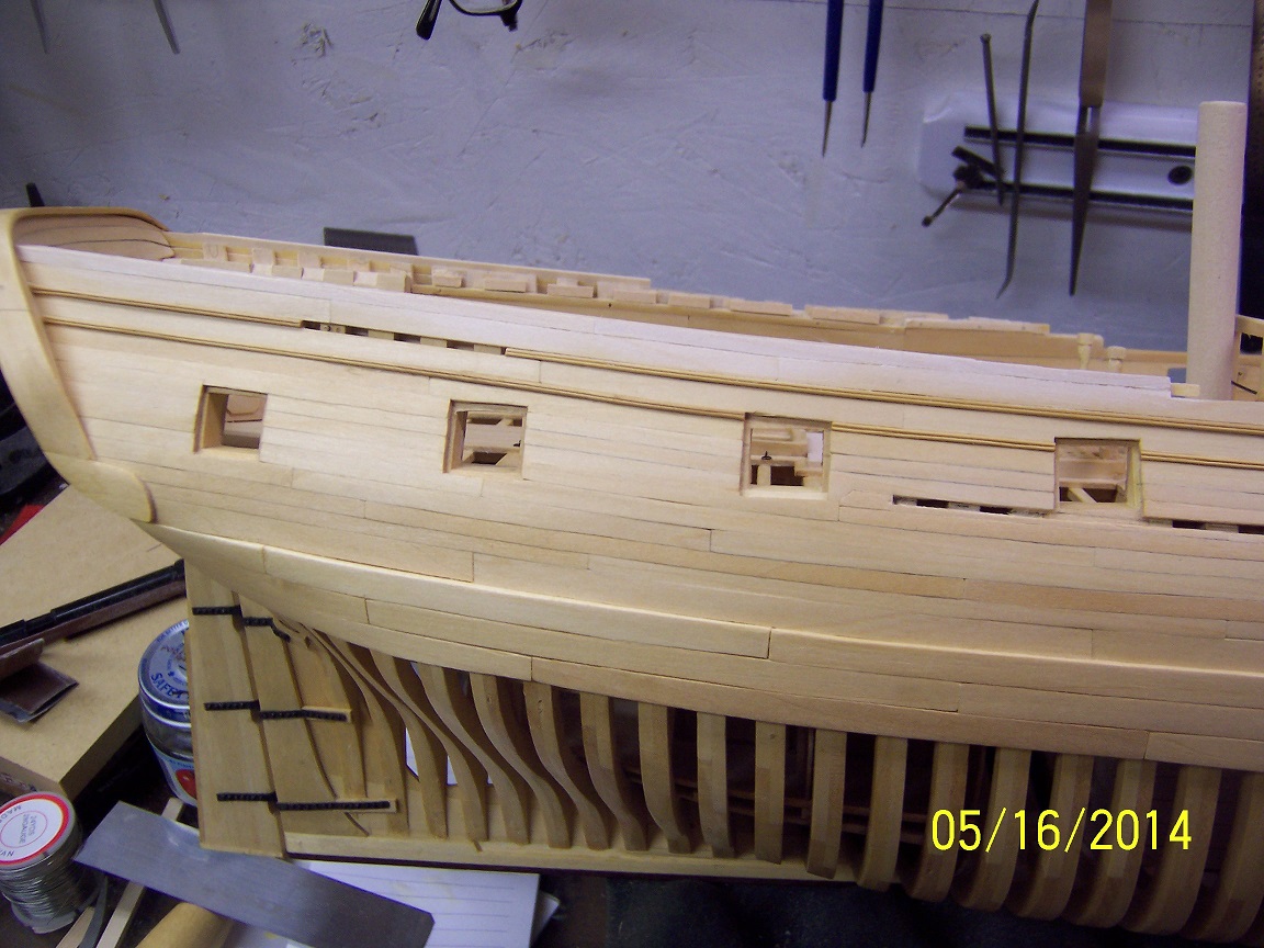
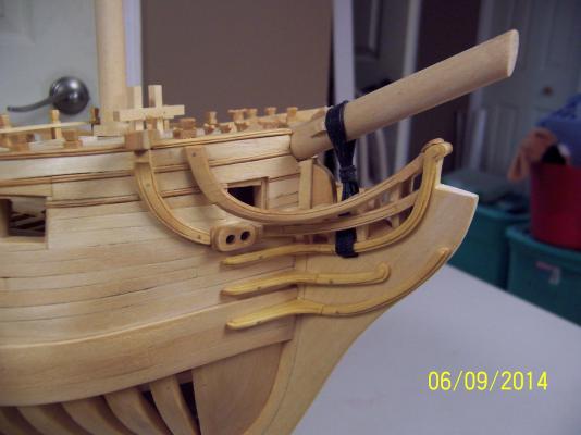
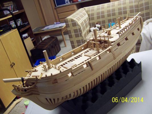
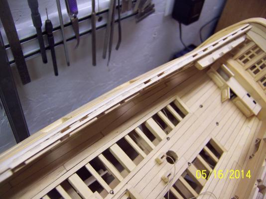
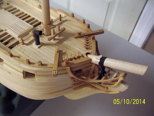
 A quick update: Put in the Eking rails (from hawse holes to cathead). The question was to bend the rail to fit the hull or carve it out of a larger block. With all the angles and variations present (to include the thickness of the eking rail) I opted to carve it out. To give the hull a more finished look prior to hitting the wheel and channels I tried a little scroll work carving on the rail transitions: Definitely found that some times the carving goes fast and successful, and other times slow, painful and scrap. Trying to put in an hour or so a day. Mark
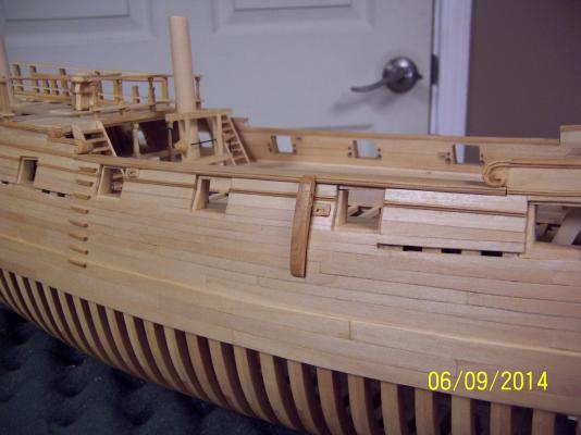
-
I really like this ship subject. Something a little different. Great ideas on the windlass, ended up with a better product! Keep up the great work, Mark
-
Lou! I knew you would be back. You really need to update your build log (so I can shamelessly take ideas to the Lady Anne post this build). The figurehead is slated as pretty much the last item (which means it is coming up fast). My current thought process shows a robed figure with the hood off of his head and for that little bit of craziness he will be holding a fish. Next week I am hoping to start doodling up some 1:1 size possibilities. David and Russ, sure appreciate the nice comments. Stay Building My Friends, mark
-
Thanks for all the likes and looks! Progress continues.... This afternoon I put a first coat of gel coat on after completing the starboard side railings. Still some minor improvements but I think I can chalk up the quarterdeck railings in the complete column. I got a little ahead of myself last night when I had the mid-railing complete to the full posts on the starboard side, but with no cutouts for the partial posts (those with the timber heads). I of course patted myself on the back and promptly glued the railing into place. Horror set in 30 seconds later when I realized my issue. My mind raced on how to cut the holes while the railing was in place but luckily I calmed down and slowly worked the railing out of place. Another minute or two and this would have been impossible. I left everything for the morning and 10-15 minutes of work cleaned up all the glue residue. Stay Building My Friends, mark

- 268 replies
-
- 10
-

-
Not too much to say but angles, angles, angles! After a whole lot of time measuring, cutting, sanding and thinking I am finally on top of one of the quarterdeck side rails. Lot of effort into pieces that will pretty much visually disappear if done right. Unfortunate in one respect, but it is what it is. I am going to take a break for a day before hitting up the second one. Stay Building my Friends, Mark
- 268 replies
-
- 13
-
-
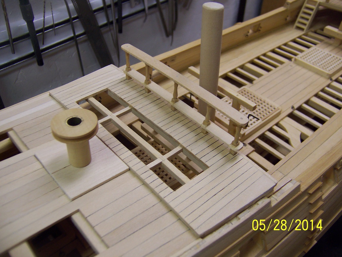
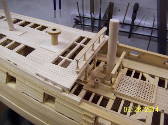
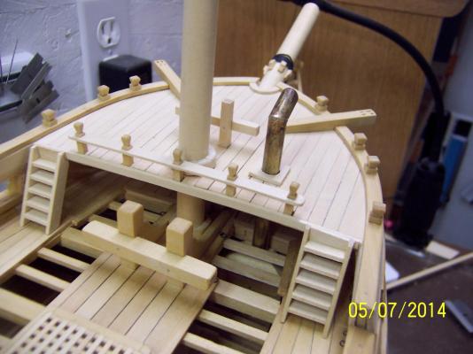
So with the case somewhat settled I have moved back to the quarterdeck. The capstan sat unfinished so this evening I sat down to right this situation. The only thing left is to string the bars once everything settles and dries. The lower bars will remain off. It was even tighter down on the gun deck. The front faux panel separating the cabins would have to been taken down to give sufficient space for its use. I did have a good laugh when I was thinking how I could add the bar spacers and insure the bars still came out at the correct angles. The answer to affix the bars first, then the spacers is obvious but sometimes the obvious isn't so obvious. Up next are the side railings..... Stay Building my Friends, Mark
- 268 replies
-
- 10
-
-
Thanks for all the thoughts. I have zeroed in on a 14 degree angle. This is NOT a slip way angle, but more extreme. It does show that a case height of 16.5" is sufficient. In the future it would be relatively easy to lower the angle (even to level) and the case would still fit. I will have two clear acrylic posts supporting the hull with two slimmer rods providing lateral movement support. My goal is to have much easier access to viewing the deck cut-aways (or even having people notice that they are there). There is no focused ship modeling audience in these parts so I am looking at this as displaying a piece of 'art' for most people. Well, the options stay open but I have a plan and can get this cover ordered. Internal volume to be covered: Height: 16.5" Length: 31" Width: 10.5" The total base will cover: Length: 34" Width: 14" Not too small but manageable. I have a space in the family room that will accept this size so that is a good thing. Now I can get back to that capstan. Stay Building My Friends, Mark
-
Blackie, Way back when I was going through the same thought process for the Lady Anne to do the exact same thing. For myself, I ended up thinking this was a primarily a working ship and not a man-a-war so I decided to use lift out ports. They have planks stretching across them inboard which are secured against the bulkhead. When required, they would be unsecured and then lifted in towards the center line of the ship for stowage (let me know if I need to sketch this out). Just seems more in keeping with the type of ship I envisioned. I in fact was going to secure two of my guns parallel to the bulwarks against the affixed port lid to maximize the usable space and get the gun pretty much out of the way. I haven't totally worked out the rigging for this but know I will do it this way. Totally up to you, of course. Mark
-
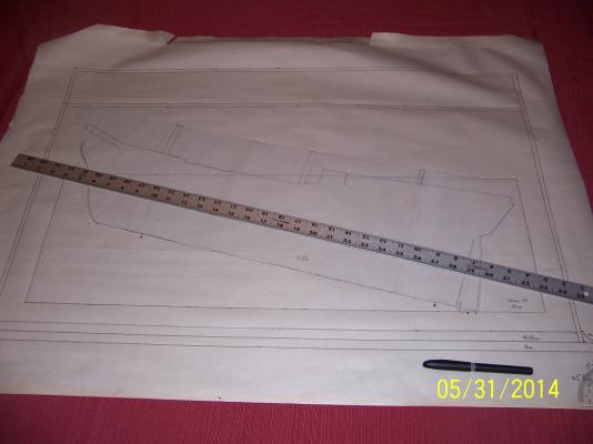
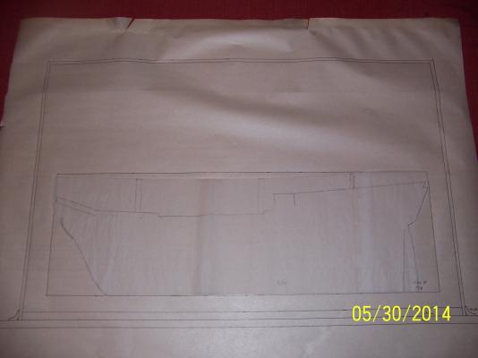
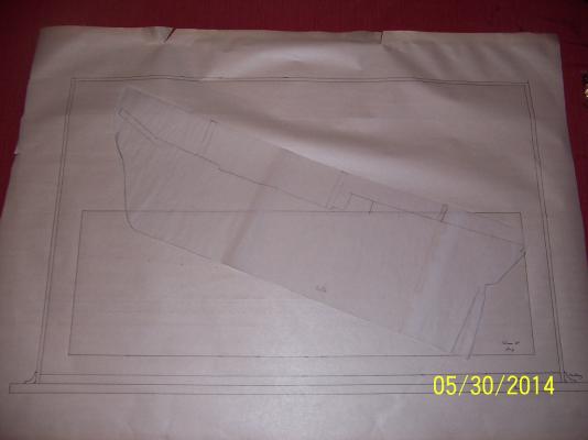
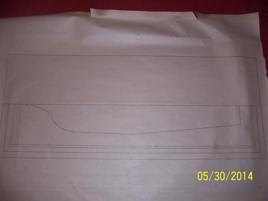
Welcome back Blackie, I know my Lady Anne sits patiently and will be there when I'm ready. Thanks for sharing your research, I will stash in my build area. Beautiful work. I would add a 12" ruler next time so people can realize this size of this build. I have no idea where I will put mine when it is done but it is the journey and not the end. Keep up the photos! Mark
-
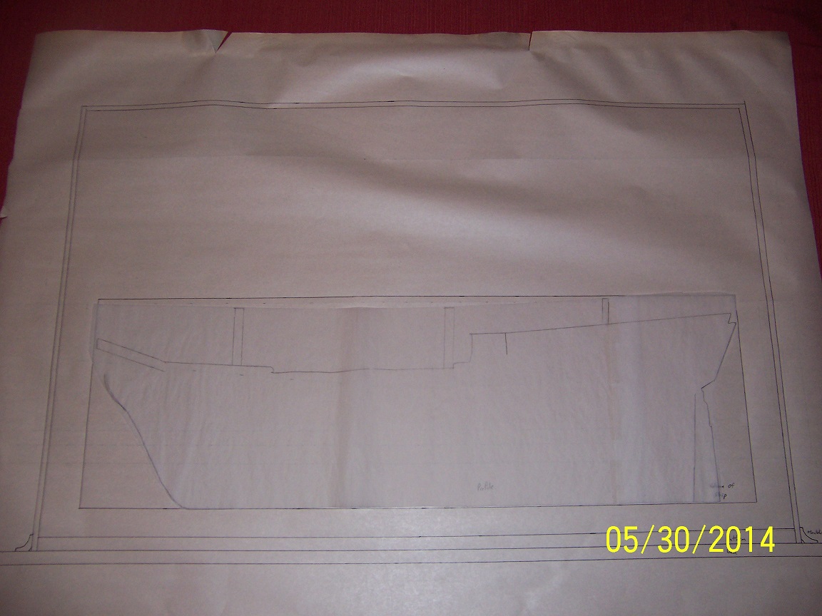
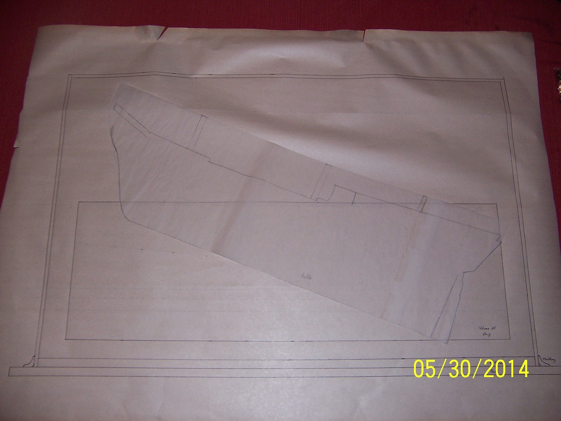
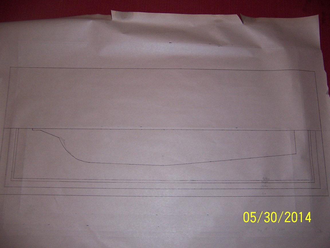
Taking a bit of a side trip to scope out the case for this model / monster / piece of art. I am contracting for a seamless plexiglass cover so this is necessary to define the dimensions If you expand the pics you should see my sketches much better. First off was defining the necessary base: The total dimension was 35" by 14". Pictured is the bottom base, the molding against the plexiglass, the plexiglass and finally the platform on which the stand will be mounted. The platform will have a piece of black fabric covering it. The base and molding will be stained oak. The big question comes to the height of the case. If I went with the traditional approach the following picture would be all that was necessary, with a resultant height of 13": However......given all the cut outs my wife suggested maybe an angle would work better such as: This could add as much as 7" to the height (20" total). This is more extreme than being mounted on a faux launch way. The posts holding the ship up will be acrylic and I will cast specific clear resin clamps for it (another post). I just wonder if anyone has any thoughts on this approach. Stay Building My Friends, Mark
-
Well, that certainly didn't take long....Makes total sense. The view I have is a clean build / model. I think the capstan bars provide that cleaner view (plus providing a bigger visual entity) than omitting and adding the binnacle instead. Plus everyone recognizes the capstan bars so I think I have talked myself into my decision. Mark
-
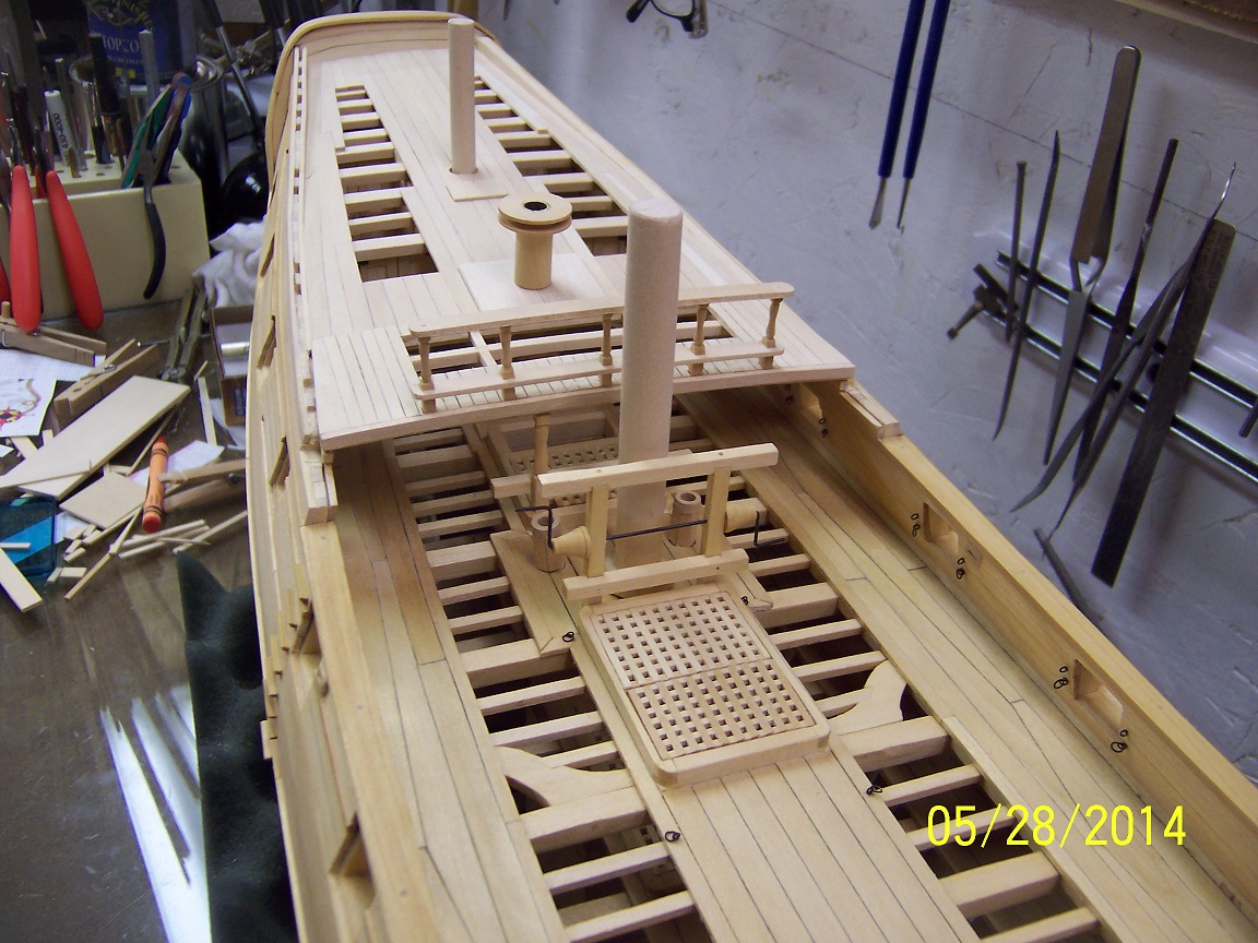
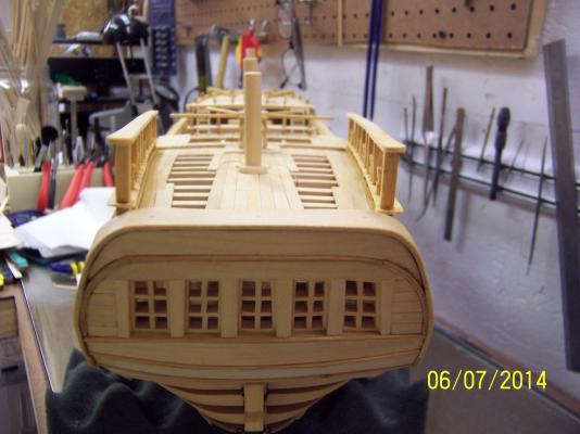
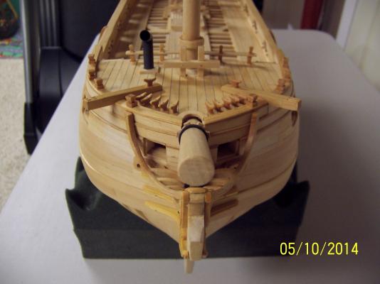
Thanks for all the looks, likes and comments! I am starting to feel a bit of disbelief that this build is coming to a conclusion (not without continuous challenges and hurdles to overcome). Forged ahead to the quarterdeck extension: LOTS of lessons learned here (hah, hah): 1. Always be aware of part orientation (which side is forward, which is back). This is particularly true when cutting mortises for rail columns. Luckily not a huge issue since the aft side is hidden on the deck beam. 2. Always be aware of whether or not your measurements include or not include the floor planking. That can sure ruin a lot of hand carved rail columns if they are cut too short. Sometimes you get the bear, sometimes the bear gets you. I was able to work through my Mark made issues and eventually persevere. When I had originally completed the quarterdeck extension I planked the whole section solid. Standing back and looking at the result the little voice in my head (cause of so much additional work) clearly stated it just didn't go with the rest of the build and had to be modified. I went back and cut the view ports in. It does look a lot better. The capstan is still entirely removable. I did think of a issue to think through though: I have decided to add the capstan bars to the capstan on the quarterdeck. The radius of the bars is somewhat evident and extends almost to the ships wheel. The problem is the binnacle. Its location puts it right in the middle of the capstan bar space. I am thinking that the binnacle was removable when required. Looking at the Hahn photos he did not include a binnacle (nor is one shown on the plans). I am starting to think to add tie down points for the binnacle but not include the actual one. Any thoughts? Stay Building My Friends, mark


- 268 replies
-
- 10
-
-
I guess the question is does the builder have a plan about how the planks will lay across the whole hull. It looks like they are getting some close line up of the plank ends which isn't optimal. I would guess they are doing single planking (double planking it wouldn't matter at all) and are really focused on the joinery at the bow and stern. It could turn out fine, my gut just says it would be harder making sure everything lines up from bow to stern. I don't think I will be going in this direction. Mark
-
I finished the original quarterdeck planking. Now I am moving on to the extension built on by the British. This is complicated by needing to build the deck railing between it and the gun deck prior to the planking. The British added this so that the required capstan addition was usable. That this wasn't originally planned for the ship will be seen with the resultant cut away cap railing and exposed section of the extension where the ladders will be. The railing will still end at its normal place and that was a head scratcher for me for awhile before I remembered the ratlines / shrouds for the main mast occupy this space and provide the same function (perils of not thinking about a fully rigged ship!). Stay Building My Friends, Mark
- 268 replies
-
- 10
-
-
No problem Eamonn, Seems like forever but it was back on page 2 of this build: General Finishes Gel Topcoat Wipe on Urethane Satin Those top rails are the big builds left (forgetting the figure head for the moment). Everything has a plan, just need to execute. Maybe end of June. Mark
-
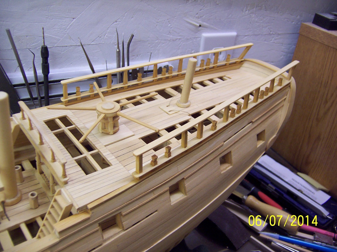
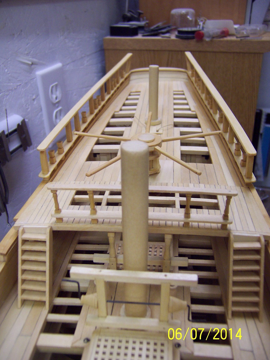
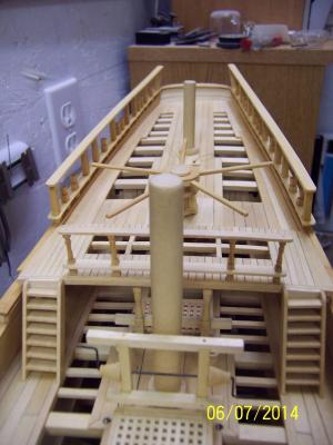
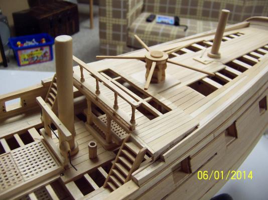
Still working away when the time is available. I continued with the lower capstan (very limited viewing) to try out some techniques and am pretty happy with the result. I do have some build improvements for the upper one. I still have the bar partitions to construct. The idea has popped into my head to install the bars in the upper capstan on the finished model. The quarterdeck is a little 'empty' and I am thinking why not. Of course, more time required to this already lengthy build but who is counting..... I had a bit of an a-ha moment when I realized I did not need to finish these things prior to getting the quarterdeck planked, in fact it would be preferred not to have them in the way. The important item was to have the raised platform for them roughed in. Until I glue this platform in, I could take the assembly on and off. So, on to the (last) bit of major planking on this ship. I have settled on the lower half as the completed look I was looking for. This was a bit of free style work. What gap to keep is totally up to the builder. Most that I have seen of this type is much smaller, but I wanted to have as good as possible look at the partitions and captain's cabin below (not to mention to even have a chance at the orlop deck work I did). The plank divisions will pop when I gel coat this. Still quite a few things on the list, but it is dwindling. Stay Building My Friends, Mark
-
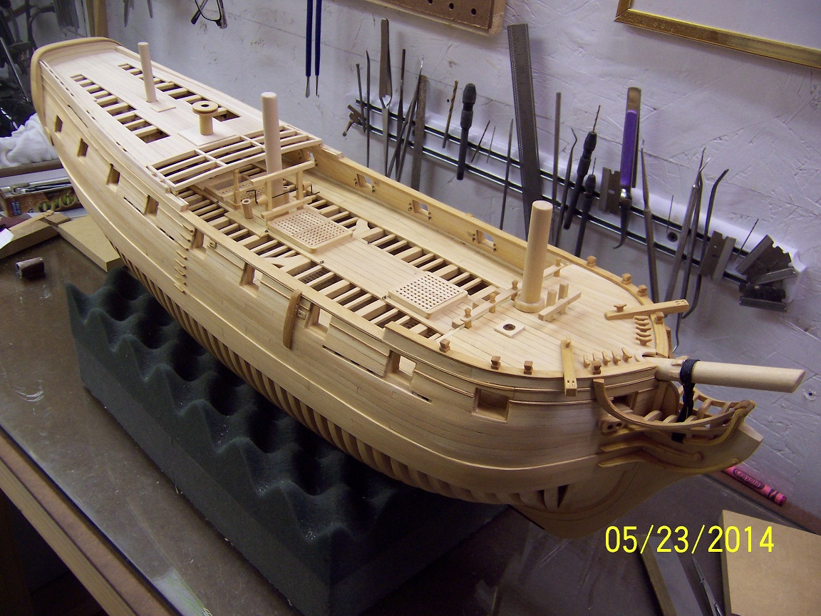
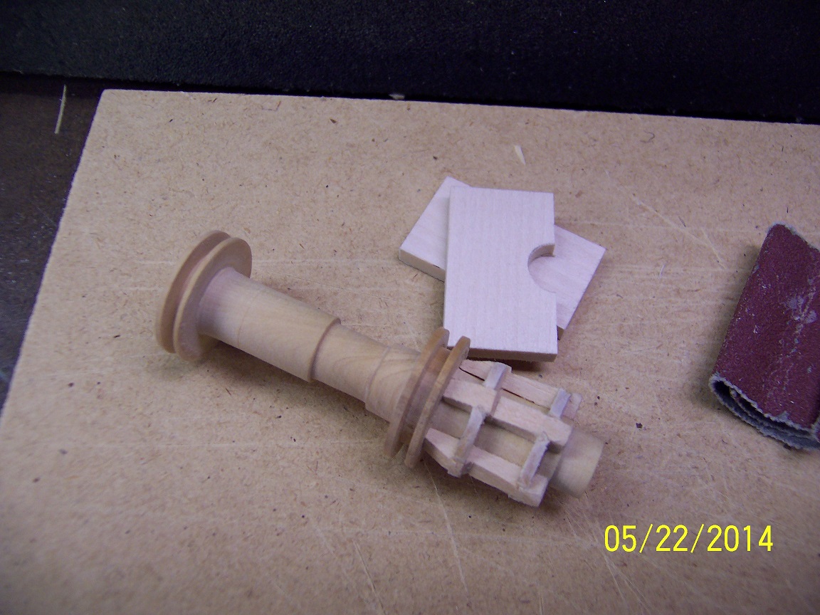
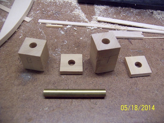
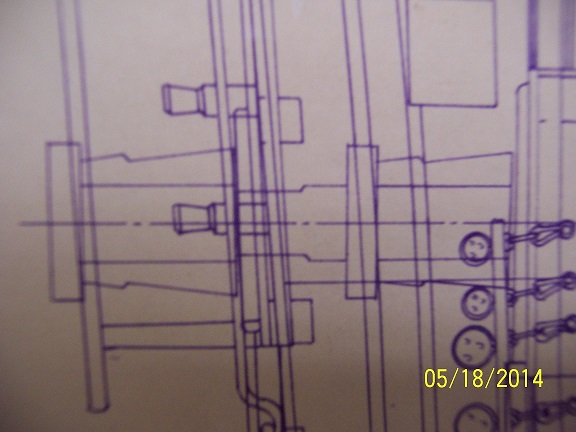
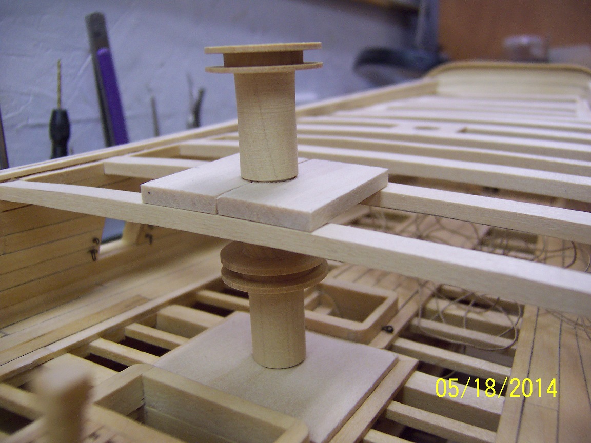
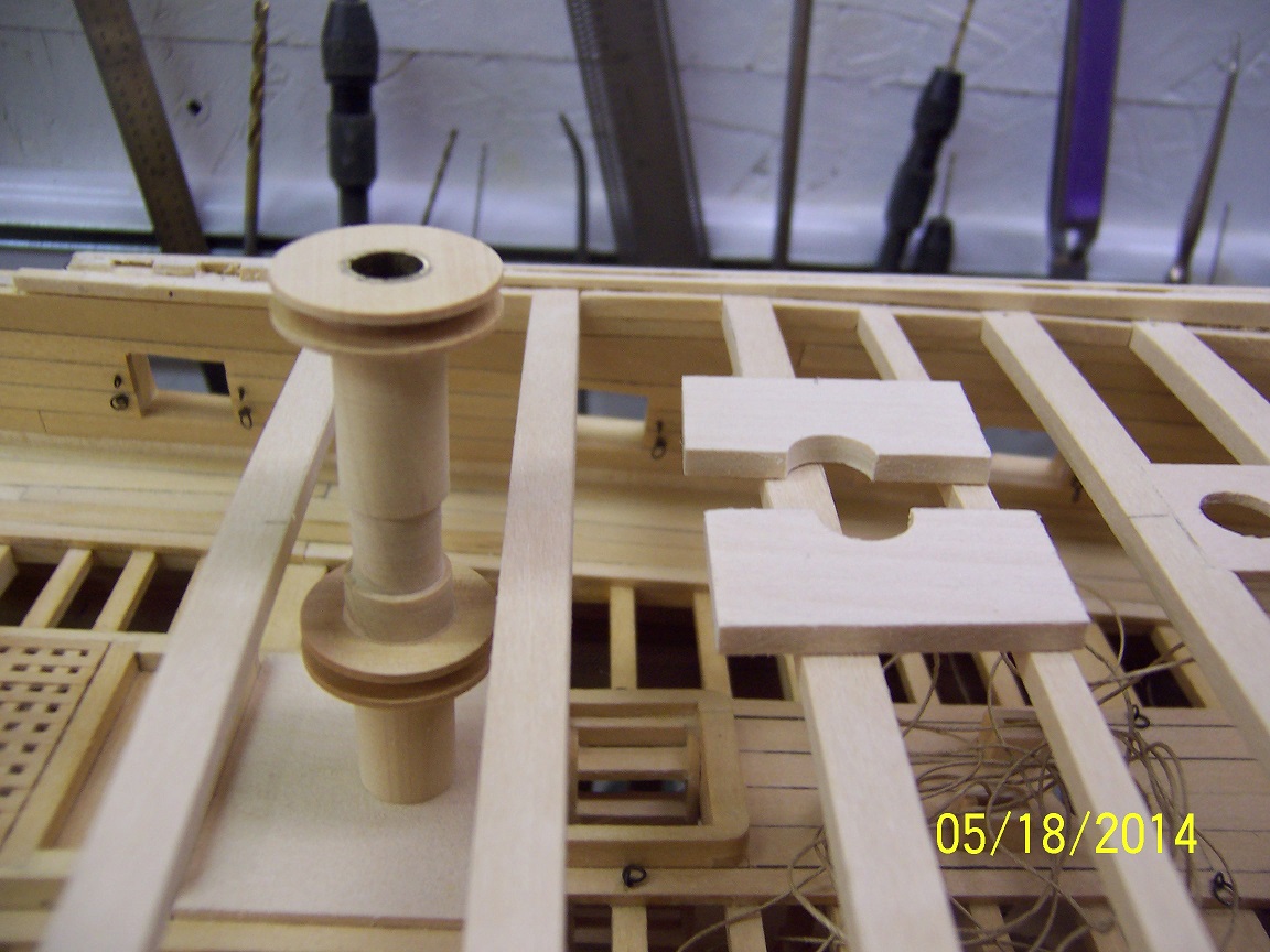
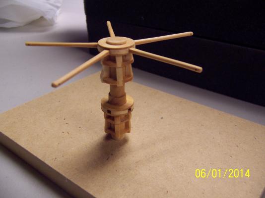
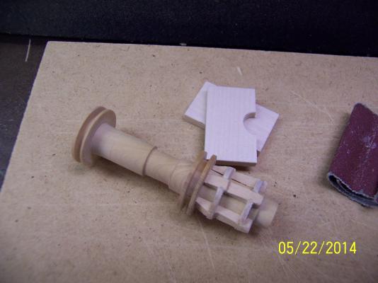
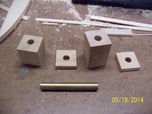
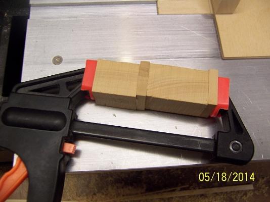
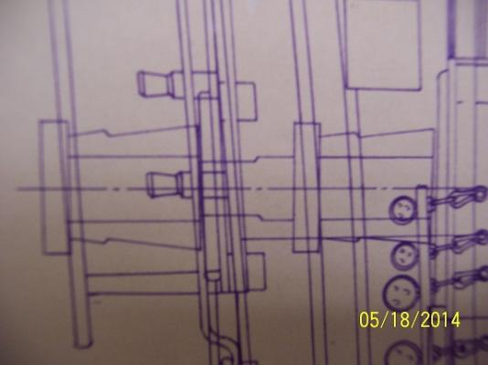
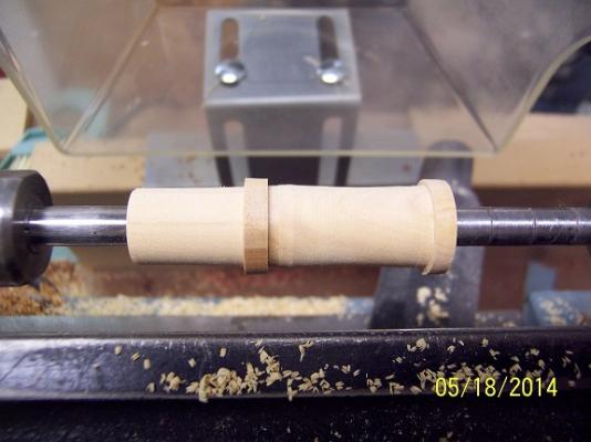
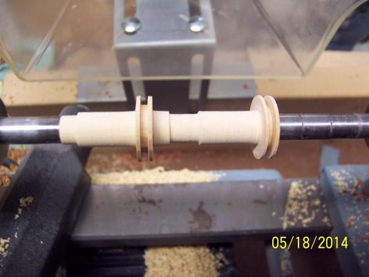
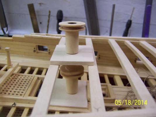
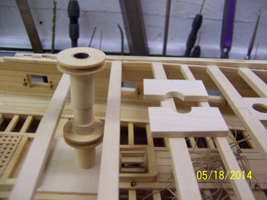
Okay, not trying to puff myself up but I am pretty proud of my capstan. I did join a couple of hobbies in the process, bringing in my pen making side business. The capstan is quite a few pieces most of which are cylindrical - not the easiest to construct well. So....I thought long and hard and came up with a way to do all the round pieces on the lathe, which is what it is used for. Both capstans will be made as one single piece. I first cut blocks for the main axle as well as the component that holds the bars. Then I cut a 7mm hole through the centers of each. A brass tube will be glued in to this hole to provide structural rigidity (the pen side of things). I did alternate grain directions for looks, but also to allow the bar area to be cleared out eventually. All the pieces were then glued up, with the brass tube superglued in: You can see in the drawings the targeted portions of the capstan to be turned on the lathe: Then it is a 'simple' process of turning to the desired dimensions. Since I have that brass tube I can mount the component on a steel rod and use bushings to lock it in place. Very strong. I drilled a hole in the base plate that the capstan fits down cleanly into. I then cut another baseplate for the quarterdeck and cut another corresponding hole. This plate needed to be split in half to fit around the tube and result was better than I expected: I love it when a plan comes together. I will lathe a small cap piece to cover the hole on the top of the capstan and then cut the other components required against the axle. Very doable. Always happy when you come up with a plan and it actually works. Stay Building My Friends, Mark

- 268 replies
-
- 11
-
-
Thanks David. I am actually compensating for issues raised over 12 years ago when this build first started. I like to think I have matured and grown enough to overcome these things. It will be all good. I had wanted to keep things sturdy and boy did I over engineer. Interesting to think I am saying goodbye to the rib tops that I have been staring at for so long. The evolution of Krug. Mark
-
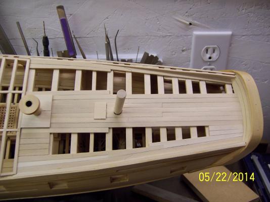
On to the quarterdeck. First business was to get the sidewalls correct (width and height) to set the tone for the cap rail as well as planking. BIG lesson learned here in regards to the ribs. I should have left extra height on the ribs and did some extra measurements on target widths. Luckily, there is a path to recovery which will be totally invisible once complete. To highlight the issue the following photos is the current situation with a pencil line denoting the target width on the tops of the ribs. This extra will be cut away down to the tops of the quarterdeck beams. It will be noted that there essentially is no protruding ribs at the forward end of the quarterdeck. To remedy this I removed the top layer of planking on the external hull (a partial width) and will replace with a wider plank. I will attach pieces to this plank to replace the missing ribs and provide support to the internal wall. Now, we are talking millimeters not meters of missing material. If you look at the previous picture and view across to the other side you can see where I have already done the necessary work. It is important when sanding the resultant wood down to the finished dimensions that you use a piece of sanding block that stretches across the hull to insure a totally flat surface for the cap rail. The forward end of the new wall ends up flush in height with the floor planking of the quarterdeck then does a gradual rise up to the stern wall. When complete the pictures look much different: The floor planking goes flush against this new material which will provide a finished look and clean join. The cap rail covers all the ribs and support structures so all this work will disappear if done correctly. Having a good foundation is essential for following up with all the finishing touches (and provides relief from stress) Stay Building My Friends, Mark

- 268 replies
-
- 10
-
-
Mark. First off, you don't need any boxwood for the ribs, keel and other lower hull parts. The first pieces I used were for the scroll work on the stem which was pretty far into the build. I went with the Lumberyard for the boxwood. I essentially budgeted $50, thought about what thicknesses I need and what proportion for each then ordered. I have MOST of that wood supply left, almost barely touched it. Don't worry about the boxwood right off. Figure out a hull that interests you and start from the basics. Plank on bulkhead is even an option. Mark
-
thanks Mark, you should do it! On a side note - the cleats are boxwood. This is where basswood breaks down. If you omit the drilling for the dowel you have a chance, but the grain is just to soft for the fiddly bits. Except for the boxwood I have purchased all my wood at two local hobby shops as I needed it. Mark
-
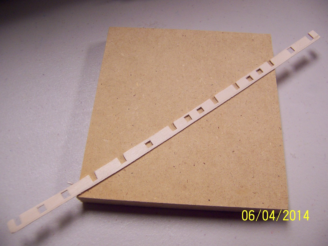
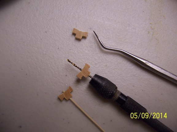
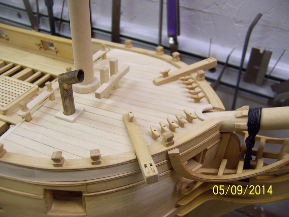
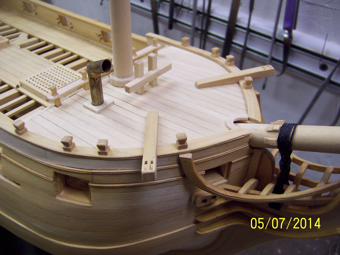
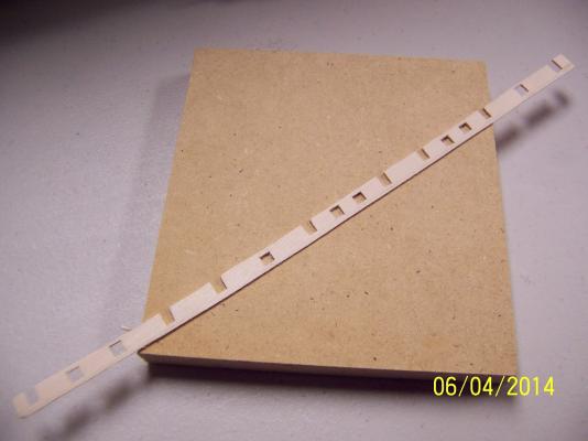
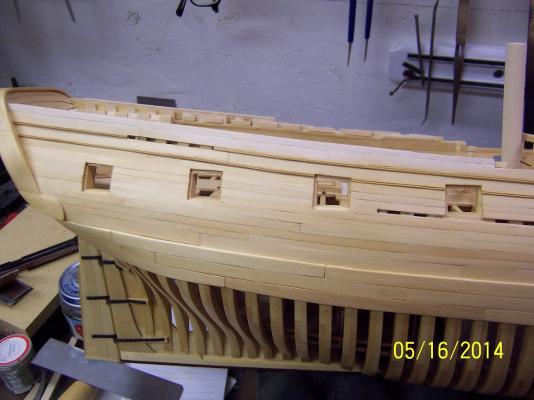
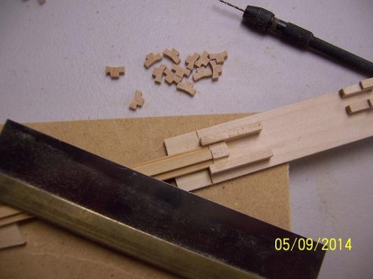
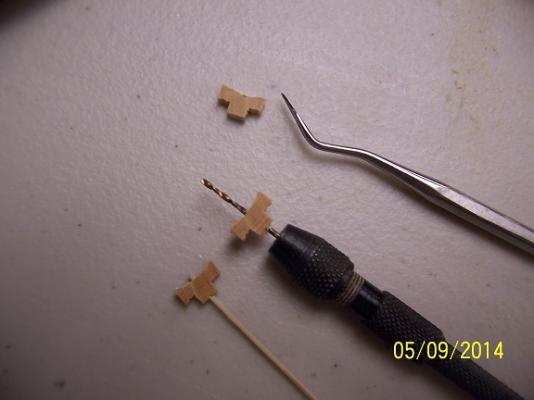
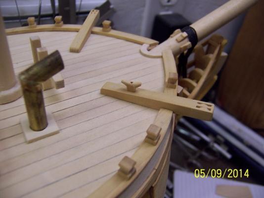
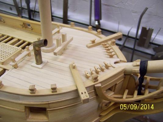
Before I take a week hiatus I really felt pushed to try to get the cleats in on the forecastle. I am sure if the ship were rigged there would be a lot more of these things around the hull but I have opted to just put 12 of them at the bow. After figuring out the size I wanted to achieve I cut out a strip of wood to the rough dimensions, then used a Dremel to rough out the inverted arc on top. I then used my razor saw to cut out the widths: Just gluing these to the deck was asking for trouble with such a small glue area, so while I had some good flat surfaces I cut a hole for a dowel through the middle: Now for the fun part - sanding. Each cleat took 5-10 minutes of work to round all the corners and shape it to the desired configuration. FIngertips are still sore from that. I did take a sharp knife to expedite in some areas but very slow and steady. Upon completion I checked the result against the ship and it seemed in harmony: I arced in a line where these should reside then checked off their locations using my proportional dividers. I glue tacked them to the deck: Once they had dried pretty firm I drilled through the previous holes into the deck. I followed this up with a dowel and some glue for a real solid bond. Once that had time to dry, a light sanding to finish everything up. Shortly after I gel coated the whole forecastle (the foremast is not fully seated in the following pics to allow it to dry). Now when I stand off and look, that bow sure looks a whole lot better. Still have that eking rail but that will be for another day. Oh - I will carve a scroll piece to transition from the top rail to the gun deck rail to clean up that transition. A good day in the shipyard! Stay Building My Friends, Mark
- 268 replies
-
- 12
-
-
Peter - So glad to hear from you again! Great news that you are back in production. Just as I talked about not masting and rigging the shipwright shows back up who is doing just that. Can't wait to see the progress. Stay Building My Friend, Mark
-
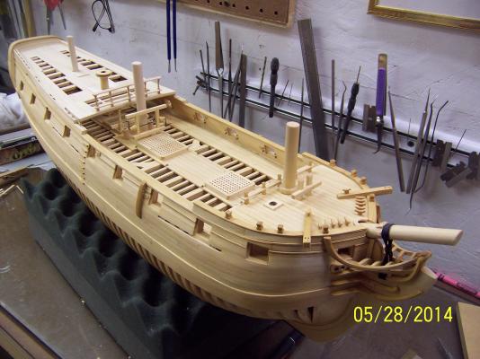
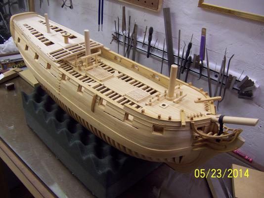
Thanks Joe and everyone else stopping by. I laugh a little when I look back at this reboot starting in Aug of last year. At first glance there is NOT a ton of difference apparent between the profile then and now. However, I think of all the time and things accomplished and this delta can be explained. Not a hobby for those wanting quick results! My wife rolls her eyes a bit when I explain the time still remaining. I don't even want to think about what it would have been had I selected to mast and rig her. I will do the complete scratch one day, but can only fit one of those in my house. The Druid is good in that it will fit pretty well on a wider shelf space. Taking a break next week to do things with the family so that will fortify me for the final push. Stay Building My Friends, Mark
-
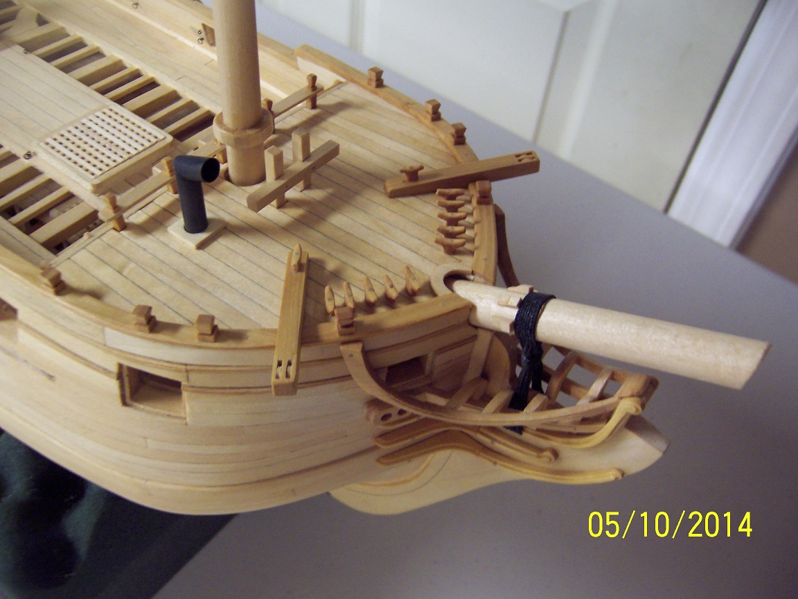
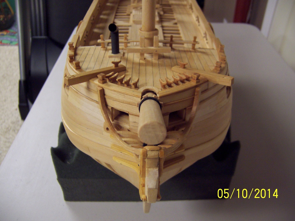
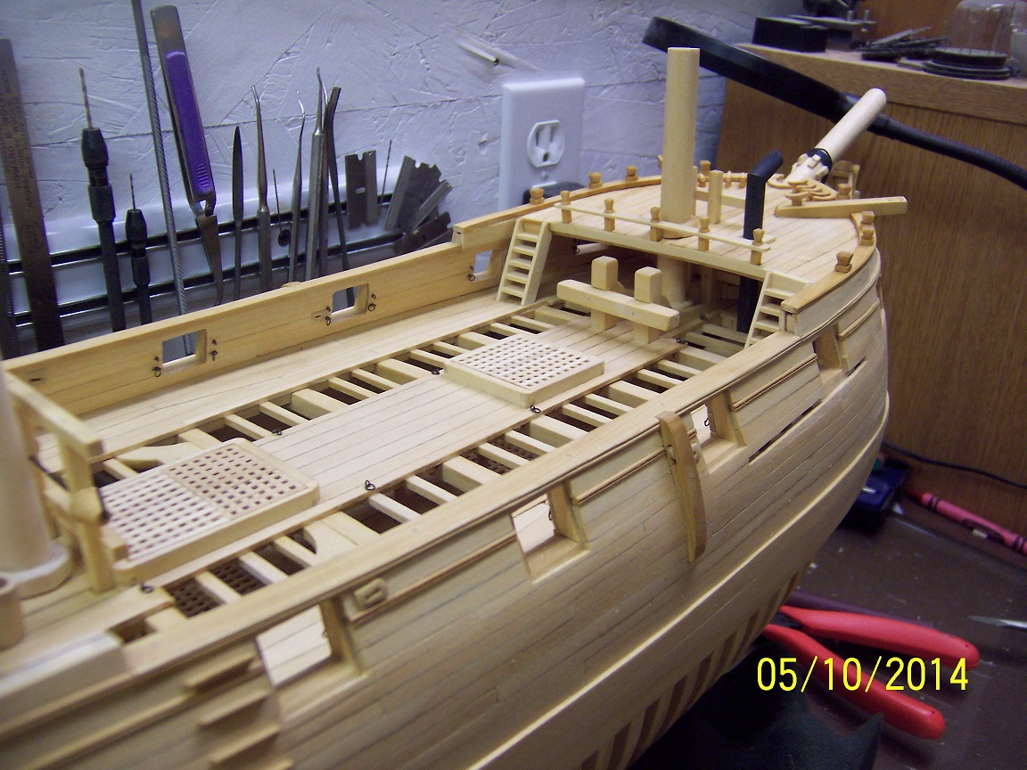
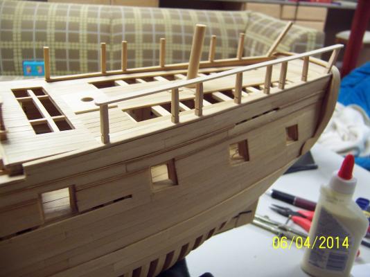
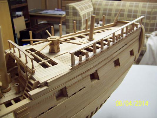
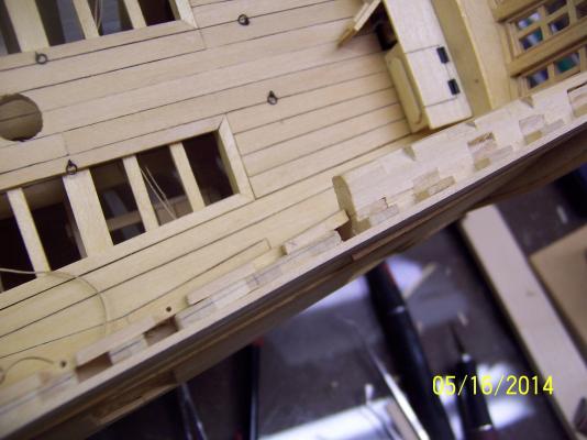
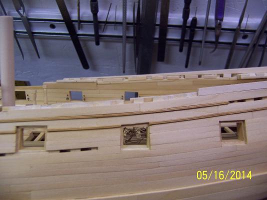
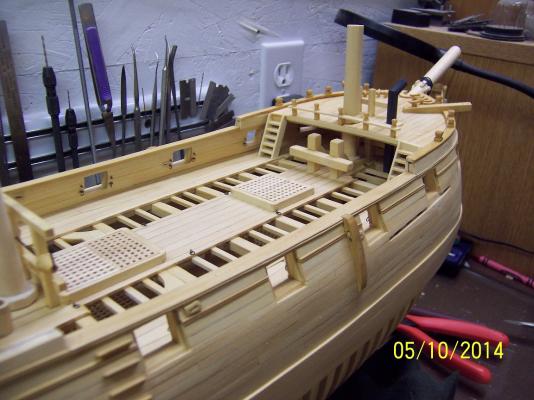
It seems like every day I add things that now make a significant difference in the look. Yesterday was the timberheads, gluing the cap rails down and assembling and fastening the ladders. I have talked / covered how this was done in other parts of the build so I just attach some new photos: Boy, that camera angle sure makes those ladders look totally crazy width wise. That is optics. I have the cleats, blackening the chimney and the eking rails left before gel coating and moving back to the quarterdeck. Stay Building my Friends, Mark

- 268 replies
-
- 16
-