HOLIDAY DONATION DRIVE - SUPPORT MSW - DO YOUR PART TO KEEP THIS GREAT FORUM GOING! (Only 20 donations so far - C'mon guys!)
×


kruginmi
-
Posts
629 -
Joined
-
Last visited
Content Type
Profiles
Forums
Gallery
Events
Everything posted by kruginmi
-
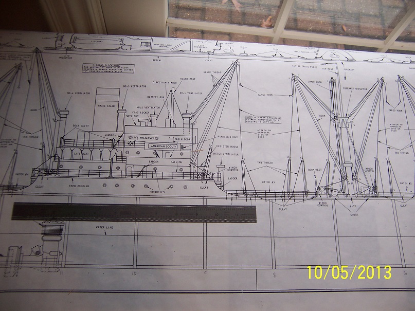
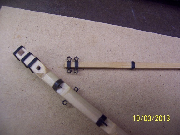
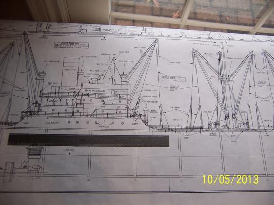
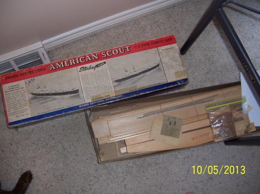
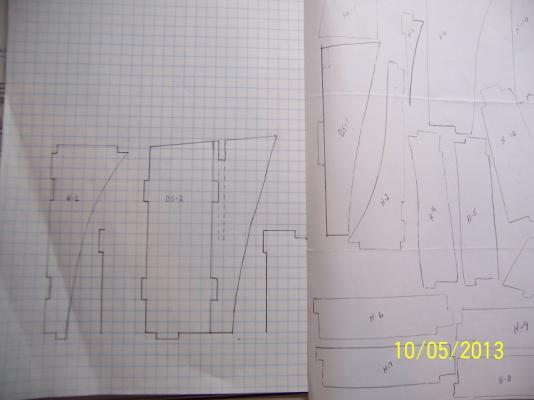
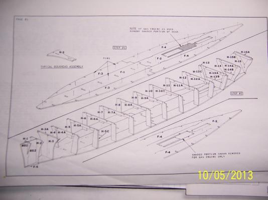
 An oldie but goodie. Originally designed for R/C but I intent to build it as a static display (at least for now). With my other builds on the dock this is currently a mental exercise to recreate those pieces that have gone awol - but maybe I get ahead of myself. As with a lot of my current kits, they were 'gifts' from associates that knew I dabbled in these things. Usually started with the best of intentions, they were cast adrift for one reason or another and finally donated to me instead of thrown away (thank goodness for that). In this case this beautiful ship was started by someone's grandfather who passed away. Unfortunately a good chunk of the work he had done had gone missing. Fortunately, he had just started so this primarily consisted of the internal hull bulkhead components. This is not a standard size ship, and the bulkheads are not standard as I have previously known them. I have the baseplate shown below, just missing the outside pieces. In previous years I had been in dialogue with another kit owner (though non-builder) who kindly offered to trace their pieces. This was accomplished but was definitely 'in the rough' and not builder ready. So my current activity is to define a legitimate definition of these bulkhead pieces that could be used to build the kit. Below right is the traced components, below left is my current efforts. From the plans I have the top dimensions (though I have found contrary to drawn dtails, they include the addition of plank widths), and the bottom dimensions from the base plate. My first quandry is the size of the pieces traced and provided to me essentially lead me to believe the false deck will need to be shaved, over a 1/4 inch in some places. I am currently inclined to believe the false deck(s) and modify the tracings so they gracefully go from the base plate to the deck. My plans do not include body lines. Anybody out there have any experience with this kit? My wife somewhat recoiled in horror at it's size, but it is different. The wood has not aged well and most of it will be replaced with basswood going forward. There is an accessories kit for all the winches and stuff but it goes for BIG $$'s on ebay when they show up so those items will be scratch built. I may look at what the differences are between this and a liberty ship (like the Jeremiah O'Brian) and maybe go in that direction. I don't know, at the start the sky is the limit. Like I said at the start, currently working at the drafting to define the missing pieces. mark
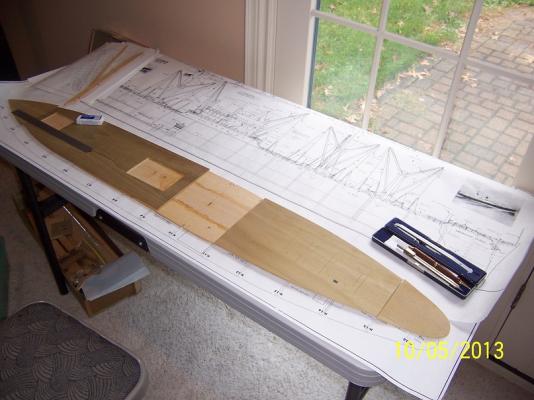
-
Thanks Mij, John and Lou. I am hoping you won't have to follow too long, because the build has been too long! First quarter 2014. Not a drop in the bucket but I believe it is achievable. It is good to be over a big hump, but the next one is right ahead. Mark
-
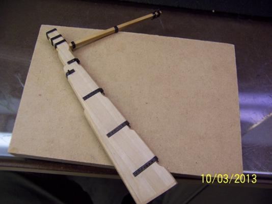
Still working along but good to see some progress. All I have left on this rudder is all the scale nails to hold the strapping on - hopefully tonight. The top three bands and the tiller arm bands are from wrapped paper. These areas are not seen on the finished ship so I thought it a great place to try out the technique. Worked very well and I will add to my options in the future. I added a faux end post on the stern of the rudder. The actual tiller arm was cut down to a more manageable square and inserted into a hole that was initially drilled then squared off. You can't tell. The backup up tiller hole had to be more lifelike but after methodical progress turned out great. The true test is to try out the resultant work in the space and see if everything lines up. Success. I love it when a plan comes together. I need to power through those scale nails. I had no idea how much effort and beauty rudders have. Chemistry, metallurgy, shaping, joinery... If you can do a successful rudder you can do an entire ship. Mark

-
What, no cup holders? That certainly was quick. Looks great makes everything tidy. Mark
-
A lot of good ideas. I usually go straight for the most difficult and these pretty straight forward ideas are great for working through the (very thin) deck material. Thank you one and all.
-
Oh, don't be surprised if you are looking to use the PoB plans for the rigging, the amount and type of pinrails will be significantly changed. On my Lady Anne I had to significantly alter my deck tie downs to use them. mark
-
Lou, You have to include a binnacle! I wouldn't leave home without one (heard that in a commercial one day). The tiller will be belayed to the bulwarks and the steersman probably not standing right in front of it so I think you have room. As always, as captain you make the call. But I throw my hat into the get'r done column. BTW: Beautiful work as usual. You really knocked it out of the park with that tiller arm. Mark
-
Brian - I have found the insetting of the metal strapping provides positioning that is rock solid and exact. Even without any sort of 'nails' it takes effort to remove them. I keep thinking about years from now (if the ship even survives!) on what will be the first thing to fall off in the dead of night and then try to figure out how to mitigate the issue. The Rudder is HUGE in my thoughts. Realistically, it will fall off in the first month after installation when I catch it on something. Now I can be assured that instead of being wrenched off, it will just drag the whole hull with it off the workbench (hah, hah). On the hull side of the rudder I am still deciding: 1. If I will replicate this process. My initial thoughts are to do so for the previously mentioned benefits. 2. Should I provide 'faux' planking under the straps (since it is un-planked in this region). I am thinking against this and just use the frames as is. Mark
-
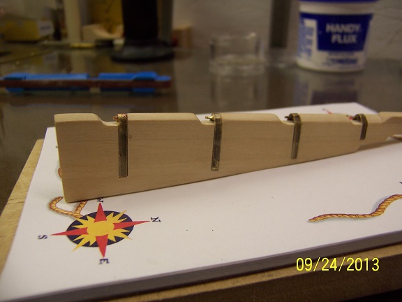
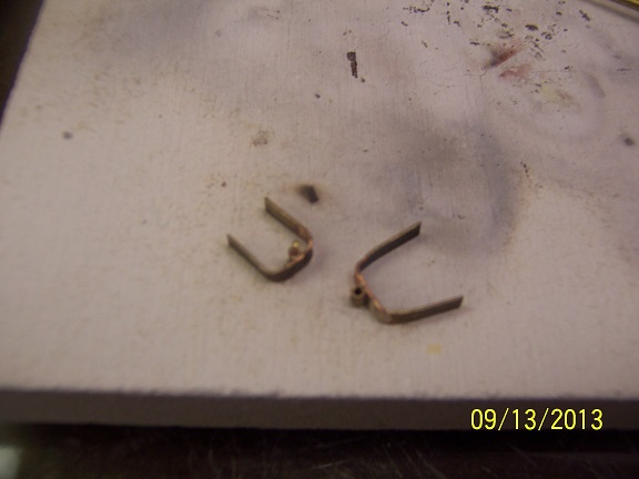
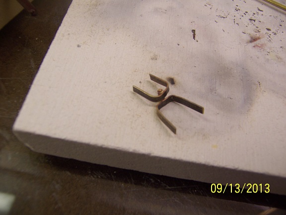
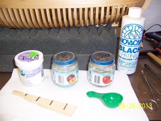
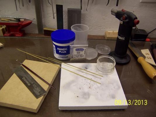
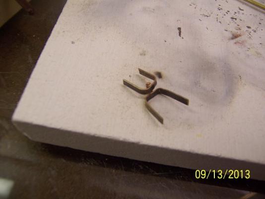
Thanks Brian and Lou - slow but keeping at it! I started to blacken the metal and thought I would share my approach (this did not come easy at first!) The process includes three containers that each metal piece goes through, acetone, blacken it (thinned) and finally water. I will not touch the piece until it has finished through the process, only with forceps. The acetone is used to thoroughly clean the metal and is left in for 10 - 15 seconds, with some mild shaking of the container to insure no air bubbles or contact with the bottom of the container is masking some oil. Upon completion the parts are patted dry. On a side note, I get my acetone in small quantities by going to the nail polish remover aisle of the general store. The blacken- it solution is 1 part patina, 10 parts water. Any more and the solution produces globs of black stuff that wipe off the metal and is quite messy. This was my initial mistake years ago. The green measuring cup is from a Miracle-Gro mix and is perfect - the small end for blacken-it, the large end for water. The parts generally go in for about 5 minutes or so with some mild shaking again. Again, patted dry upon completion. The water is to wash off any blacken-it remaining then a final patting dry. The results on the top two pieces of the rudder metal work are the result of this process. Pretty straight forward one you have the right chemicals! I have opted to hand drill the holes in the metal and other than sore fingers the going is fine. Tomorrow I hope to make some scale nails, finish the drilling, and get the metal work affixed. I am thinking about adding rudder chains so that may be a little more work. Cheers, mark
-
I'm with Cap'n Bob. About 95% of my Druid is basswood and I have no complaints. I will continue to do so. I just used a gel urethane to maintian the wood color. Mark
-
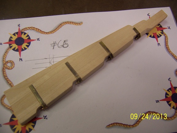
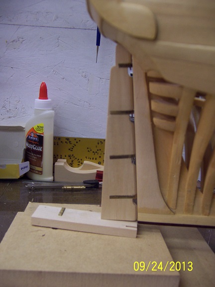
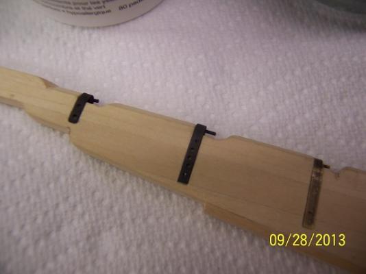
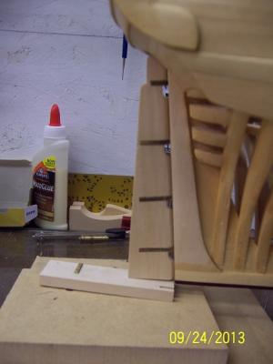
Slowly plugging away at the rudder as time allows. With the silver soldering finally set right I can move forward. The metal work still requires the nail holes drilled and then blackened but I am happy with them. After soldering the three pieces together it took about an hour to slowly bend and fashion it to the correct profile. After I was satisfied (and the length was cut to its required length) I did mark its profile and chisel it in. As is seen in the pictures, the pieces stay put rather well even before glue and nails. I want to have the rudder work totally done and rock solid before I start the hull side to keep the variables to a minimum. Still have a rear wood piece on the rudder and then eventually the tiller arm. My goal is to have the rudder basically done by the end of the weekend. mark


-
Thanks Derek, I like that technique a lot. I will have to look around for a jewelers tap and die. It makes a lot of sense. Mark
-
Hey, looks like someone has actually been making some good progress! I like the stern fashion pieces and the deck house. I was targetting something very similar for my build (if I can finish all the house painting). Always good to see your work. Mark
-
Thanks Rob for the vote of confidence. I am still very much a neophyte with silver soldering. It was key for me to find someone who already did it (in my case he did jewelry) and could specify exactly what equipment / supplies I needed. Then it is practice, practice, practice. Future growth for me sees ordering more silver solder with a different melting point (I think something like 4 types available). This allows you to attach multiple pieces together without undoing any previous work. Sounds good in theory. Still working to get those holes drilled and verify I have a path to success without destroying the rudder. Mark
-
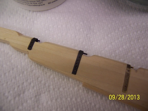
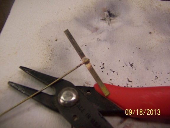
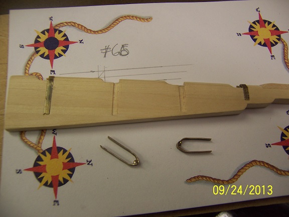
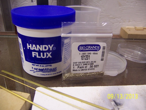
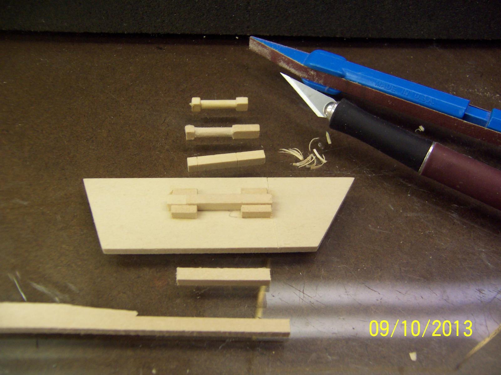
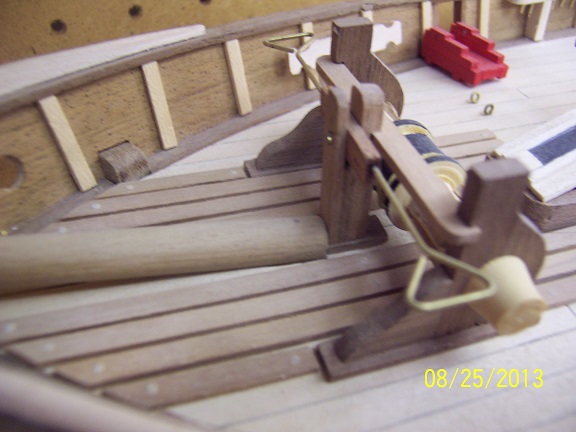
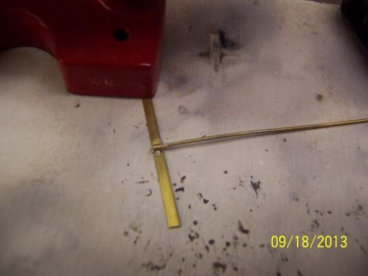
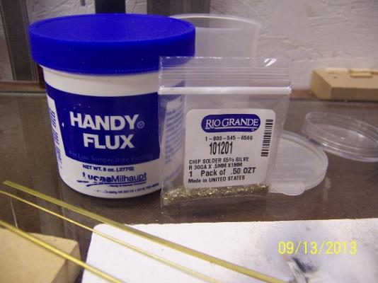
Finally - the replacement for my silver solder flux showed up in the mail today! This hobby is not just for learning things about wood! It starts that way, but then you have to branch out into all types of finished (shellacs, urethanes and all things acrylic). Just when you get comfortable, metalurgy comes to the forefront and the chemistry of soldering. My mix of supplies are: This flux works like a charm where all others have failed. For the gudgeons and pintles (rudder work) I needed to replicate the look with what I had available. With some thinking I opted for prototyping using some brass strips, tube and rod (that fits into the tube). On the hull side I soldered a section of tube to the brass strip on the outside facing. On the rudder side I soldered it on the inside and added a section of rod to allow the two pieces to mate. This result is still very much in the rough for fitting to their wood sections but I believe the end result that is possible is acceptable. Now I have to fashion the final assemblies for all the attachment points and insure I am able to drill holes through the brass sheet to allow for the nails. I am currently assuming to make an indent at the right drill locations in the brass, probably use a bit of oil for lubrication and slowly make each required hole. These will be small and I am hoping to not sacrifice too many bits. Suggestions are always appreciated. Mark


-
Brian, yes this is 1/48th. I chose this model (so long ago) because of the limited carvings and lack of quarter galleries. Being a converted merchant ship the internals are also a little more open. Some interesting areas are the forward area of the berth deck, which the Royal Navy lowered to allow inclusion of the regulation ship's stove and the extension of the quarter deck to allow the windlass to be included. I am undecided as to which Hahn model is next up for me. I try not to think too much about it and keep at the task at hand, however the Oliver Cromwell jumps out. He has a lot of other plans that i don't see being made here, though, so those also call. The 1/48th scale is perfect for me and the detail that is achievable with my thick fingers and tools at hand. It will always be my first choice. Mark
-
I got all the beams painted (carilngs and ledgings too) on the sides and underside but nothing photogenic so I skip the attached pic. I did notice I had not finished the gun deck supports so I had to get a few manufactured. I dug around my odds and ends box and found the original (simple) jig I had made for those things. Wasn't too long before I had the ones required made up. I do dowel them into the lower deck but skip this step for the top end. Just too hard to get everything aligned. My biggest hope was to fashion the metal work for the rudder. Pulling down my supplies I found my flux had dried up to look like some meteor just fresh through the atmosphere. I could not find the stuff local and spent days and $$'s trying other stuff that just didn't work. Finally ordered the original stuff and hope to get it later this week: Handy Flux for soldering or brazing gold, silver, brass, copper 8 oz. Hopefully more progress to show soon, Mark
-
Thanks John, I think my 'safest' place stayed so for a little over two years during and after a house move. I stashed some of my best hand tools and current project (rudder for the Lady Anne) in a ship kit box to insure their recoverability. I looked everywhere for those things and even replaced some of the tools. Well, that ship kit was stashed and never looked at until one day when I just happened to pull it down and then that a-ha moment, and complete recollection. I think some old age might be coming into play. Mark
-
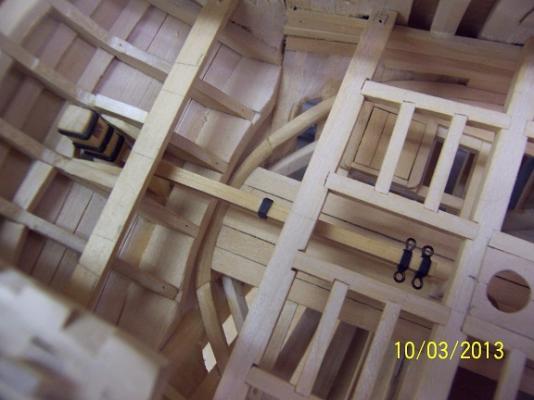
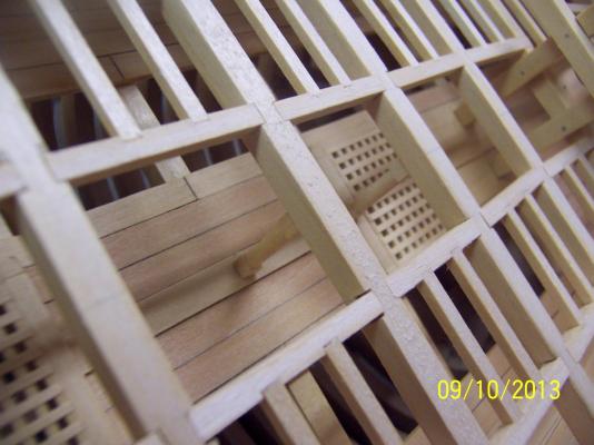
Thanks, Christian - I don't trust myself for measuring anything! Either created spacers or dividers for distances right off the plans. Brian - I think it will be worth it. Some more of the unknown has been broken apart for the next build! On the subject of painting, I have been steadily working around the hull giving a couple of coats. Hopefully done by the end of this weekend. I did go down memory lane, however. I needed to remove the gun deck floor to give brush access to the berth deck (the lower holds will stay as is). It had been years (literally) since this had been put in and i couldn't remember if it was glued or not. I gently worked from each end and was relieved to find it wasn't. Each carlings and ledges grouping is glued into a unit but still free from the deck beams. That floor was solid even without glue and I patted myself on the back. I ended up with a couple of boards full of pieces - NOTE TO SELF: DO NOT DROP, PUT IN SAFE PLACE, REMEMBER WHERE SAFE PLACE IS. The berth deck as it exists today: As is normal with Hahn plans because of the amount of flooring and visibility, there are no knees. I am sticking to this plan. A little more clean up required but this level is essentially done excepting the rudder. The rudder arm should go underneath the gun deck beams and through rigging have the lines go up the middle deck area to the steering on the top deck. (next project). Some more memory lane items was the recovered stove. Basically cannot be seen but the stove pipe can. In keeping witht the theme of the build, it is constructed out of basswood: You might have noticed my Krugism. When I started this build I wanted to have a distinctive feature, a feature that would readily identify this as a Krug build. You may have noticed that this hull is essentially uni-color EXCEPT the false keel. For that I used Purple Heart wood. That's right, Purple Heart. It definitely darkens with time, it is hard to see regardless, but I am thinking not too many other model ships out there will have this 'feature.' Finally, I have started mocking up the name lettering on the stern before I attempt to carve them out of boxwood. I haven't done really any investigation on preferred font or sizing but my first guess is 'Stencil' size 20. I will ponder this some more. Thanks for looking, comments welcome. Mark


-
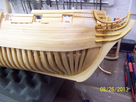
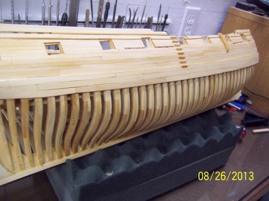
Finally got the time to put one coat of the gel urethane on the starboard side (to include in between the frames). In the picture of the bow the location of the eking rail was left 'in the raw.' Due to lighting issues, the bow pic is a little washed out. This wasn't that hard to apply at all. It made the frame components really pop and highlight the plank joins. I am still looking at applying another coat. This was a good thing to do and I am glad I was pushed in this direction. Mark

-
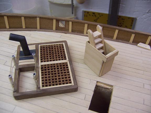
I was wondering when someone would notice this! Bonus points to you Floyd! In my defense there is a wall at the bottom of the stairs....(hah, hah). Right now I have no specific plans to change it (you are the first to point this out) but I may get a flash of brilliance, who knows. An easy quick fix is to reverse the stairs, but I don't know if I have another railing piece (photos above are older, see previous overviews for how they were redone). Mark
-
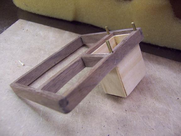
Lou - that looks Great! Your planking looks very clean and I love the wood choices (a little jealous). Talk to me about your rudder box and what you intend there (might be borrowing right back....). I see it is time to bore out the bowsprit hole, good luck there. Mark
-
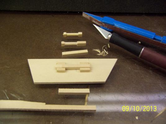
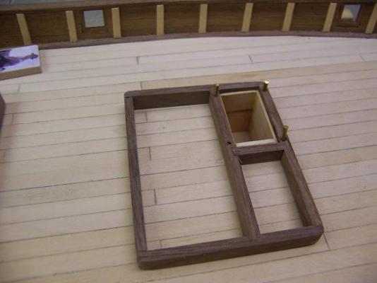
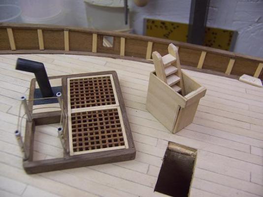
One item on this ship that I saw someone else do that I knew immediately that I was going to copy was the stairwell going down to the lower deck. In a PoB - and one that has the hull complete - how would you do this? The answer is to make a self contained box and lower it into a cut hole in the deck: In the following pic you will notice a slight indentation at the top of the box. This was to allow the box to slide down next to the center bulkhead. The box is painted black below deck level to allow the illusion of desending. I really like the opportunities this provides both on this ship and others. An easy implementation with good results.


- 128 replies
-
- 5
-

-
- artesania latina
- Finished
- (and 2 more)
-
Lou - looking forward to seeing what you come up with! Floyd - I have no idea how many stealers I have offhand, but my process on kit cover the hull planking is to take a long strip and position it correctly midship. Then I let it flop forward and aft, where it lays flat against the hull. This lay of the plank is marked in with a pencil. Then the long plank is cut into whatever length planks I feel like and glued down on this line. After a few runs, you will see where the stealers are required. I do not force the planks to do anything but lay flat against the hull (which is what they want to do). I do start with the bulwarks and go down to the turn of the hull, then start from the bottom and work up. This gives you that almost smiley face mouth plank as the last plank in the center of the hull but is pretty quick. On accurate planking this a first step to identify where to diminish planks and to understand where the difficult parts of the hull are, but i won't get too much into that (because I didn't do it that way on this ship). I appreciate all the compliments. Maybe I should show this to my kids to show them I am not crazy.....(I would have to figure out how to stop them texting first). Mark
-
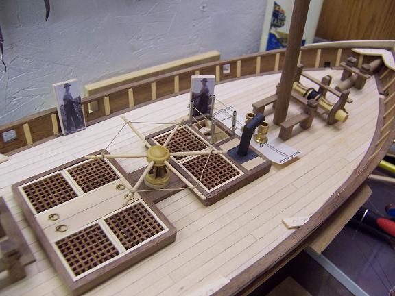
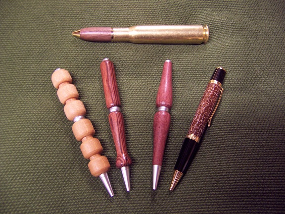
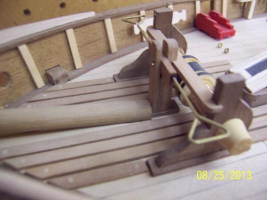
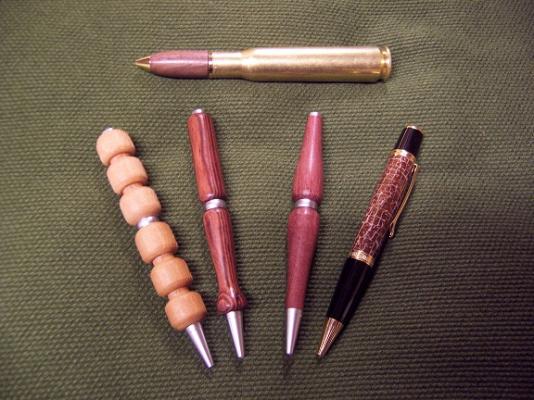
Lou and everyone, I feel obligated to state again everything I have done has been for the fun of it. I have no problem sharing, just don't want people to think I have done any big amount of research and is the last word on the subject (hah hah). I did have to laugh when you mentioned my windlass, because my first thought was the capstan. A capstan made from the kit part with cut down wooden cocktail toothpicks for arms! However, I figured out you meant the forward windlass (which I am pretty proud of). I can't locate the pictures of it being built unfortunately but I did design it out beforehand and lathed it using boxwood. The lathe was procured not because of the ships, but to make pens: This is a related hobby that actually brings in some income! The best part of this is that I get to really understand different types of woods. Their look, how they sand, how they finish and their usability in the future. A bonus is I do get to use it occassionaly for ship related articles. On the camera topic, I use an (older) Kodak EasyShare DX 6440. The big discovery was the ability to go into close up mode. This has to be selected and produces very clear images. They are not achievable otherwise. I then edit them to resize to 25% normal size. If anyone particularly wants one larger, PM me and I can send it out. For the bowsprit I flatten it a little where it meets the deck and butt it against the windlass: The stem defines the angle of the bowsprit. It really is up to you on how you want to terminate it, but by lodging against a solid beam, less deck area is taken up by it. To insure the position is fixed I did drill through and dowel it into the deck. Cheers, Mark
- 128 replies
-
- 1
-
-
- artesania latina
- Finished
- (and 2 more)