


Elia
-
Posts
539 -
Joined
-
Last visited
Reputation Activity
-

 Elia reacted to jcoby in Pride of Baltimore II by jcoby - Model Shipways - Scale 1:64
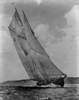
The angle of the mast is close to correct in that picture (within a degree or two). The mast is set at 15.5°. It looks more extreme because the ship is not level.
I made a couple of jigs to set the masts once I get to rigging:
-
Elia reacted to jcoby in Pride of Baltimore II by jcoby - Model Shipways - Scale 1:64
Progress has slowed down again now that the weather has turned nice. Plus I managed to get the flu followed by conjunctivitis. Having a kid is a great way to get sick.
Apparently I used the wrong stock when I made the engine access hatch. It ended up being 1/32" too small in both directions. Instead of making it completely from scratch I just glued on some 1/32" stock to bring it to size and then transferred the hatch covers to a new top. After a coat of paint it's unnoticeable.
I also added the stowed pump arms to the engine access hatch. Those are the smallest pieces I've had to make so far. The arms themselves are 1/64" in diameter (~0.015") and are about 3/32" apart. I also had to make two sets because the plan callout for the arms was scaled about 30% bigger than it should be. It worked out for the better because I stained the first set the wrong color.
To break up the monotony of working on the deck details I've been concentrating on getting all of the rail details done. I have all of the cannon eyelets and rings installed and have finished all four of the cleats where the mooring lines go through. Various cleats go on next followed by some strips in the cannon openings and the ladders.
-
Elia reacted to jcoby in Pride of Baltimore II by jcoby - Model Shipways - Scale 1:64
I installed most of the cannon eyelets today. There are four (two on each side) that get installed on the fore side of the stanchions. I'm not sure how I'm going to drill for them. I may just drill a little crooked and push them into proper position. The basswood is pretty forgiving in that regard.
I also put a coat of primer on the trucks for the cannon. These things are tiny but still seem too large to my eye but I am not changing them. They seem to fit in the gun ports with a bit of sanding on the wheels to make everything flat.
-
Elia reacted to jcoby in Pride of Baltimore II by jcoby - Model Shipways - Scale 1:64
I spent some time on the various eyelets tonight. I installed the 14 deck eyebolts and two that go on the stern knees. You can also see in the picture that the pump and fire hydrant are more bronze than the other pictures show.
I then started on the eyelets and rings that hold the cannon in place. I found some 0.011" brass wire from another kit. I wound it around a #70 drill bit but that turned out to be far too small for me to work with.
So i switched to a #61 and that seemed to be OK. I wound tight coils and then split them off with some small side cutters. I then flattened them in a set of smooth jaw pliers. I made 22 of them even though 20 were needed. Turns out that they go shooting off very easily and I needed all 22 of them!
After that I held the eyelet in a set of small hemostats and used tweezers to bend the eyelet. I inserted the ring and then flattened it back out. The result is passable at this scale I think. It doesn't match the plans exactly (they're about 30% too big) but there is no way I could work with a 0.025" I.D.
It took me as long to figure out how to make the first four as the remaining 16.
Next step is to blacken them and glue them in. I may make a jig and rig up the cannon to them before gluing.
-
Elia reacted to jcoby in Pride of Baltimore II by jcoby - Model Shipways - Scale 1:64
I spent some more time getting the fore mast done. It's complete except for the cleats that go on the octagonal section at the base and completing the trestle tree at the top.
I took a picture of her with all of the masts and booms but it's too blurry to post. It's going to be a tall model when it's done. I don't really know where I'm going to put it.
I also made up some gauges that are the proper 13.5° and 15.5° to set the masts. I'll post pictures of them and how I made them later.
I then moved on to the pin rail and fire extinguisher and bilge pumps. The fire extinguisher are made of bronze. I don't have any paint that simulates old bronze and the gold that is included in the kit doesn't look anything like bronze.
So I decided to switch to plastic model paint (Model Masters and Testors). I put on a coat of gold and then dry brushed on a coat of a dark oxide. The results are a serviceable bronze look. I don't feel like the castings are very good. They seem more like blobs that sort of look like bilge pumps.
I then attached the pumps and fire extinguisher to the deck. It feels good to finally install parts onto the deck permanently! The engine controls box and pin rail are not installed (the engine controls are backwards anyways).
Next up: deck eye bolts, deck cleats, and finishing up the details on the inside of the wale. After that I should be able to start installing the deck furniture.
It feels like I'm finally making some sort of progress again.
-
Elia reacted to jcoby in Pride of Baltimore II by jcoby - Model Shipways - Scale 1:64
Tonight I spent a couple hours working on the fore mast.
I started by spending 20 minutes straightening the replacement dowel that MS sent. It was bent in a S-curve that was at least 1/16" in each direction.
I used a set of pliers to burnish the high side while bending the dowel past straight. I ended up with a section that was within 1/32" of true. Close enough. I will be able to pull any remaining curvature out when I add the standing rigging.
After that I added the octagon shape at the base and cut it to the 13-1/2° angle called out in the plans. In the picture the fore mast looks quite a bit more vertical but it's only 2° less than the main mast. The lens on my iPhone makes it look much more than it is. It's not perfectly positioned for the picture either. I will use the standing rigging to set the masts in the proper location when it comes to that point.
It's time to clean up the workspace I think!
-
Elia reacted to Pete Jaquith in Newsboy 1854 by Pete Jaquith - Model Shipways - Brigantine
Welcome to the "Newsboy" 1854 build log,
Work continues on completing the deck outfit. Key points include:
>>> Two boats were fitted (my decision vs. one shown on the plans)
>>> Boats were fabricated from laminated basswood around a CL bulkhead
>>> Boat interiors were not hollowed out or detailed
>>> After painting, boats were dowelled and lashed in place on the forward house
>>> Anchors were fabricated and lashed in place
>>> Anchor chains were fitted to the anchors and windlass
>>> Forward and main house were glued in place
>>> Forward bell was fitted to the Sampson post
Pete Jaquith
Shipbuilder
-
Elia reacted to DWright in Bluenose by DWright - Model Shipways - 1:64
Log #4
The next step in the process is the foredeck planking. One of the previous logs had suggested that if he had to do it over again he’d seriously consider sheathing the deck with very thin ply (1/64 inch) to facilitate the planking effort. I second that motion!
I probably didn’t prep the bulkheads and keel properly and as a result realized some uneven planks that needed scraping to bring even with the other planks. A close look at the foredeck pictures will reveal that plank nibbing was not initially my strong suit. It took me about 10 nibs to begin to understand the process, but it rendered a few rather poor efforts. The unsupported nibbing strike presented a few problems as I cracked it once requiring a slight remodel.
The next event will be the quarter deck planking, but first I must figure out how the stern/transom assembly is to be handled. The plans and instructions are a little vague and even Bob Hunt practicum doesn’t really spell it out. Any comments or suggestions would be appreciated.
Darrel
-
Elia reacted to Hank in USS NEW JERSEY (BB-62) 67-69 by Hank - FINISHED - Trumpeter - 1:200 - PLASTIC
Since my last post, I was able to contact and correspond with a former Long Beach Naval Shipyard project manager who was involved with the final fitting of radar and electronics aboard USS NEW JERSEY prior to her Sept. 1968 departure for WesPac. Richard Landgraff and I have been erstwhile correspondents/battleship enthusiasts since the 80’s and have now re-established contact after quite a few years of absence. Richard spent well over 30 years at LBNSYD working on the IOWAs through the years as the needs of the Navy changed and the ships were in service and out. Currently he is involved with the USS IOWA Museum located at the L.A. Ports.
After an exchange of photos and a critique of my (2nd) mast assembly, Richard made a few observations which I have amended this week:
1) The foremast on NEW JERSEY was removed in 1967 at Philadelphia NSYD and replaced with a 36” diameter lower pole. The current available plans of NJ of this time period do not show the mast correctly. They also show the mast with a starboard side vertical ladder and this is also incorrect. The ladder is mounted on the front face of the mast; I now have photo proof of this thanks to Richard. I have removed the mast from the conning tower, modified (enlarged) the two mast support brackets and replaced (modified) the lower mast pole to achieve the required diameter ( 3/16” @ 1:200 scale) or as near to it as I could make it without major damage to the rest of the assembly. Historical Note - the original IOWA class foremasts were designed to be lowered in order for the ships to pass under the Brooklyn Bridge in New York harbor. If you compare these photos with the prior photos posted a week or so ago you will see the differences in the mast structure. I've also added the wire rope stabilizing stays on either side of the mast extending to the rear of the ECM equipment houses.
2) The forward tubular bracing I made for the lowest radar platform is not correct and was modified per Richard's directions to more closely resemble the actual bracing. In addition, side tube bracing that was omitted from the after brace was added. These corrections are not all that evident in my photos below.
In addition to the technical knowledge I have learned this week, Richard has also provided me with other snippets of battleship history (namely involving NJ) that probably no one else is aware of. This kind of first-hand lore is slowly but surely disappearing as those associated with battleships and their construction/modification take their final shore leave. I am keeping these items of lore in a separate file as they are related to me in order to hopefully preserve these stories.
One item of interest that I will share is that any photos you see of NEW JERSEY in her late 60's configuration with her 40mm gun tubs up forward of Turret 1 are PRE-deployment photos. Those tubs were removed the day I arrived on board in Sept. 1968 and Richard was supervising the yard crew removing those tubs. We left a couple days later for Westpac.
The photos show the new mast structure with only touch-up painting left to be complete. I will begin work on the 08 Level Conning Station and ULQ-6 antenna arrays next week.
Hopefully, I'll be able to "retain" Richard as my own "Dreadnaught Consultant" on this project since his 1st hand knowledge of this ship is so extensive.
Hank
-
Elia reacted to Hank in USS NEW JERSEY (BB-62) 67-69 by Hank - FINISHED - Trumpeter - 1:200 - PLASTIC
I've started on the ULQ-6 radar antenna frames and after two nights of work, I have a couple of photos to show my progress. Actually, I'm a bit further along with the lower framework, but these are the latest photos.
This phase of the build is assisted by R. Landgraff (as mentioned in an earlier post) who actually worked on the final construction of these ECM units in 1968 prior to the ship's departure for WesPac. So, I'm fairly confident that his knowledge will pay off in the long run.
While I'm using my CAD file for the overall construction of these frames, I'm thinking that they could be improved upon by perhaps being produced in PE brass and designed to be a folded-over frame instead of individual pieces as my framework is currently constructed. This would also eliminate the fact that the two frames are not 100% identical and that all the members were the same width, etc.
So, when it comes time to mount these units on the conning tower, I will probably use minimal glue so that they can be replaced with a more professionally designed and constructed set in the future.
Wednesday night I got the intial painting done and begin work on the lower "Derby Hat" framework construction that will be added below the existing framework. The actual ECM gear has yet to be constructed and then added.
Hank
-
Elia reacted to Hank in USS NEW JERSEY (BB-62) 67-69 by Hank - FINISHED - Trumpeter - 1:200 - PLASTIC
Well, the upper conning tower is complete - with the exception of the (2) 35' Whip Antenna that will be added at a later time to the angled bracket at the 011 Level. While the ULQ-6 ECM framework, etc. is not perfect, it will have to suffice until I can re-design a CAD file for making a PE brass sheet of uniform parts that will replace the current ones. This would be in order to make the framework more consistant in width, etc.
Next construction will be the 08 Level Open Conn. Station and adjoinning lower conning tower/fwd. stack.
Hank
-
 Elia got a reaction from PeteB in Arethusa 1907 by Elia - Knockabout Banks Fishing Schooner
Earlier than my steering wheel endeavor I had fabricated the cat heads and installed the chainplates. All of the deck furniture remains only temporarily placed for context.
Funny thing about the deadeyes - they don't want to stand upright, as in the photos. They lay over, free on their pivot pins...
And last, but not least, thank you to all those who've 'liked' my updates!
Cheers,
Elia
-
Elia reacted to Piet in Hr. Ms. O 19 1938 by Piet - FINISHED - scale 1:50 - submarine of the Royal Navy Netherlands in service 1939 - 1945
Thanks to everyone for visiting and your likes, it's really appreciated. This sounds like a broken record but I want to show my appreciation, if only through words.
Hey Popeye, surprise is coming babe I lucked out making the prototype, wonders will never cease. Even at this "large" scale of 1:50 the details can be rater small. I know how big some of these things can be and then divide by 50 and wow - - - that small???
Okay, the surprise is the "come-along" ratchet device to raise and lower the boom. Once I figured out how to make it I started making all the parts and pieces. Sorry, I did not make a picture of all these parts before assembling them, got too engrossed in getting it all together.
It also actually works No, I didn't make the racheting part but when I fasten a "cable" to it I can rotate it and actually make the boom go up or down and that should be good enough for a demo. I'll try to make the second one a little smaller, if that works then I may make a third one to replace this prototype. I'll have to wait till me left index finger heals some
I also completed all the 6 mm pulley brackets and a few hooks. I think it was a very productive day and I'm a happy camper.
I also tried making a thimble and got one that looks like it but is not the pretties thing though. But, it's just a prototype for me to see if I can make one at this scale and the answer is - - - probably not. I may have to think of something else that looks better at this scale. I used a 1 mm brass tube and bend it into a thimble shape. Then ground off the outside till I had a U formed shape that actually looks like a thimble but it's too big for scale. I may just have to use a thin brass rod and cement the "cable" to it, making belief that it's a thimble. No, you cannot just bend a cable around a pin and seized or spliced together like you do with hemp rope. Steel cable needs a larger diameter in the bend, that's why a thimble is needed and then it can be seized when it comes around. My guess is that they used at least 5 mm steel cable.
Well, here are a few pics for all yuns to see what we have accomplished.
This shows the "come-along" ratchet fully assembled and ready to receive the cable. The hook is just temporary so i can hang it to the swivel attachment on top of the port side gantry post. As you can see it's about half my thumbnail, not counting the ratchet handle and I have small, slender fingers.
This shows the "come-along" hooked to its swivel attachment bracket.
These are all the 6 mm pulley brackets, one is already installed to the gantry, and the two triangular interconnect brackets for the "come-along" with the 3 mm pulley brackets. One for the rear and one for the front.
This is the prototype thimble, not very good looking up close.
Cheers.
-
 Elia got a reaction from muratx in Arethusa 1907 by Elia - Knockabout Banks Fishing Schooner
Earlier than my steering wheel endeavor I had fabricated the cat heads and installed the chainplates. All of the deck furniture remains only temporarily placed for context.
Funny thing about the deadeyes - they don't want to stand upright, as in the photos. They lay over, free on their pivot pins...
And last, but not least, thank you to all those who've 'liked' my updates!
Cheers,
Elia
-
 Elia got a reaction from Mfelinger in Arethusa 1907 by Elia - Knockabout Banks Fishing Schooner
Earlier than my steering wheel endeavor I had fabricated the cat heads and installed the chainplates. All of the deck furniture remains only temporarily placed for context.
Funny thing about the deadeyes - they don't want to stand upright, as in the photos. They lay over, free on their pivot pins...
And last, but not least, thank you to all those who've 'liked' my updates!
Cheers,
Elia
-
 Elia got a reaction from albert in Arethusa 1907 by Elia - Knockabout Banks Fishing Schooner
Earlier than my steering wheel endeavor I had fabricated the cat heads and installed the chainplates. All of the deck furniture remains only temporarily placed for context.
Funny thing about the deadeyes - they don't want to stand upright, as in the photos. They lay over, free on their pivot pins...
And last, but not least, thank you to all those who've 'liked' my updates!
Cheers,
Elia
-
Elia got a reaction from PeteB in Arethusa 1907 by Elia - Knockabout Banks Fishing Schooner
continued...
-
 Elia got a reaction from IgorSky in Arethusa 1907 by Elia - Knockabout Banks Fishing Schooner
Earlier than my steering wheel endeavor I had fabricated the cat heads and installed the chainplates. All of the deck furniture remains only temporarily placed for context.
Funny thing about the deadeyes - they don't want to stand upright, as in the photos. They lay over, free on their pivot pins...
And last, but not least, thank you to all those who've 'liked' my updates!
Cheers,
Elia
-
 Elia got a reaction from mikegerber in Arethusa 1907 by Elia - Knockabout Banks Fishing Schooner
Earlier than my steering wheel endeavor I had fabricated the cat heads and installed the chainplates. All of the deck furniture remains only temporarily placed for context.
Funny thing about the deadeyes - they don't want to stand upright, as in the photos. They lay over, free on their pivot pins...
And last, but not least, thank you to all those who've 'liked' my updates!
Cheers,
Elia
-
 Elia got a reaction from JerryTodd in Arethusa 1907 by Elia - Knockabout Banks Fishing Schooner
Earlier than my steering wheel endeavor I had fabricated the cat heads and installed the chainplates. All of the deck furniture remains only temporarily placed for context.
Funny thing about the deadeyes - they don't want to stand upright, as in the photos. They lay over, free on their pivot pins...
And last, but not least, thank you to all those who've 'liked' my updates!
Cheers,
Elia
-
 Elia got a reaction from canoe21 in Arethusa 1907 by Elia - Knockabout Banks Fishing Schooner
Earlier than my steering wheel endeavor I had fabricated the cat heads and installed the chainplates. All of the deck furniture remains only temporarily placed for context.
Funny thing about the deadeyes - they don't want to stand upright, as in the photos. They lay over, free on their pivot pins...
And last, but not least, thank you to all those who've 'liked' my updates!
Cheers,
Elia
-
 Elia got a reaction from Perls in Arethusa 1907 by Elia - Knockabout Banks Fishing Schooner
Earlier than my steering wheel endeavor I had fabricated the cat heads and installed the chainplates. All of the deck furniture remains only temporarily placed for context.
Funny thing about the deadeyes - they don't want to stand upright, as in the photos. They lay over, free on their pivot pins...
And last, but not least, thank you to all those who've 'liked' my updates!
Cheers,
Elia
-
Elia reacted to EdT in Young America 1853 by EdT - FINISHED - extreme clipper
Yes, druxey, there are quite a few - avg. 8 per beam on the lower deck counting the four for each pillar, 34 beams, minus a few at the view ports. Thats around 200 knees for the lower deck. Definately justifies a production process. Wish their were a process for the ten or so bolts in each.
Ed
-
Elia reacted to EdT in Young America 1853 by EdT - FINISHED - extreme clipper
Ben, it looks scarier than it is. I use push sticks for a lot of this close work and were it not for the limited blade height on the Preac, a nice little specialty sled could be made to handle these - the time savings would easily cover it. However, I believe the key factor is your concentration - whatever aids are used - or whatever size the saw - or router, or whatever. When the switch goes on there should be only one thing in mind - finger proximity to the blade. When you feel that focus slipping from fatigue or lack of concentration, do something else. I never work at night.
These knees could also be easily sliced off with a hand saw.
Ed
-
Elia reacted to EdT in Young America 1853 by EdT - FINISHED - extreme clipper
Young America - extreme clipper 1853
Part 60 – Knees
Historical note: It is doubtful that knees were made for Young America at the Webb shipyard. There was enough building activity at the New York yards to generate profitable local business opportunities in the making of various components and selling them prefabricated to the shipbuilders. Knees were one such commodity, offered for sale in oak, hard pine, hackmatack, etc. - from $2 to $10 each, or $1.50 per inch of thickness for large sizes – according to one supplier’s price sheet. This dealer also sold floor timbers, futtocks, rough timber and plank. The pre-made knees, in a variety of angular shapes, were probably then trimmed to final size and shape at the yard.
Most of the work in this post is analogous to the work of the ship timber supplier – making a large quantity of knees that will later be fit to specific locations in the lower deck framing.
Patterns for representative shapes for hanging, lodging and stanchion knees were lofted from the drawings. The shapes of the central hanging knees were also lofted, but shapes toward the ends merely estimated. The shapes were then arranged on roughly 2” x 4” pattern sheets. These were then pasted to a 1” thick slab of wood – pear for the oak hanging knees and Castello for the hard pine lodging and stanchion knees. The hanging knee pattern is shown below.
Extra stock was left on the back of the vertical hanging knee arms to allow for fitting and beveling to the hull shape. The shapes were then cut out on the scroll saw as shown below.
The above picture shows lodging knees being cut out.
The next picture shows a hanging knee shape being checked for general fit on the bilge ceiling near midship.
Next the straight edges of the knees were cleaned up on the disk sander and then ripped off to thickness on the circular saw – shown below.
This takes two passes on the Preac saw due to its limited cutting height. Below is a picture of some 12” thick lodging knees and some of the smaller 6” thick knees for the hold stanchions (pillars).
Hopefully, these generic shapes will be sufficient to make the final knees. Some, especially the hanging beams near the ends, will need considerable adjustment to fit. The following picture illustrates the amount of modification needed on the hanging knees for the beam frame Y.
The generic starting point shape is at the top with the final hanging knees below it. Lodging knees are a better fit to start.
The last picture shows the installation of beam Y near the bow. These first two beams have no carlings, so I could proceed with them to test the installation process. This shows all of the knee types.
The lodging knees are butted together – one of a number of configurations used. There will be a ledge set into these where they butt (frame line Z) to span the breadth. Note that the stanchion is set off the centerline. The stanchion above will be set to the other side. This allowed the stanchions to be through bolted vertically to resist tension as well as compressive forces between the deck beams. The hold stanchions were secured for tension with the knees top and bottom.
This first beam was somewhat difficult to fit. Finger space is limited and the angles on the hanging knee surfaces are acute and required many test fittings. I am still working on the sequence, but so far it is 1) install the beam and bolt into clamps, 2) install dummy bolts in the knees, 3) install hanging knees, 4) install lodgers, 5) fit and install the post with the upper knees glued to it, 6) install lower post knees, 7) bolt stanchion through beam, 8) install dummy bolts in outside of frames, 9) bolt knees to the beam - a lot of steps. Install means glue.
I see a lot of work ahead before the lower deck framing.
Ed