


druxey
-
Posts
12,470 -
Joined
-
Last visited
Reputation Activity
-

 druxey reacted to EdT in HMS Naiad 1797 by EdT - FINISHED - 1:60 - 38-gun frigate
1:60 HMS Naiad 1797
Part 162– Forecastle continued
Posted 11/14/12
The parts for the forecastle breast rail are shown below.
The long strip in the center will be used for segments of plank under the knees where there is no decking. The next picture shows the stanchions and knees installed on the port side with the rail being used to hold the spacing at the top.
When this glue on this has dried the rail will be removed for final sizing and drilling of the belaying pin holes. The next picture shows work on the starboard side.
In this picture the stanchions are just pinned in place with small bits of wire inserted in holes in the breast beam. The first through mortise has been cut in the rail and the position of the next one is being checked.
The next picture shows the four posts for the belfry – the next task.
These were shaped with chisels and files – mostly files of the type shown. But the lines across the posts were first marked with a very fine edge file of the type used to sharpen Japanese woodworking saws.
The next picture shows the assembly of one side.
The three wood parts were end glued in a fixture to hold the squareness and to keep the sides parallel. As soon as the glue was fully dried bolt holes were drilled on both sides and a wire bolt – as shown – was CA glued into each. These sub-assemblies were extremely fragile until the entire completed belfry was installed.
The next picture shows the assembled belfry and the bell mounted on its beam with the ringer handle.
The copper parts in this picture, including the bolts through the posts are about to be turned black.
The next picture shows the belfry assembled and installed.
The four posts are secured into the deck beams with wire pins. This picture also shows the finished breast rails. The next picture shows this area from the forward side.
You will notice in this picture that there are no bolts holding the iron plate for the stack. Both the plate and the stack had to be removed to redo the blackening on the brass. Even this picture taken after the re-blackening, shows some brown spots re-appearing. The process used on this second treatment was to remove the wax and first blackening, soak the parts in hot TIVO solution (a pre-plating cleaner), rinse in clean water, blacken in a new batch of dilute selenium solution (Blacken-it), rinse thoroughly in water with dish detergent, dry and buff. Next time copper with liver of sulfur! I am about to reach for the paint can.
Ed
-
-
druxey reacted to rekon54 in Le Fleuron 1729 by rekon54 - 1:24
Good Sunday to all
advances Fleuron
rekon54
-
druxey reacted to tlevine in HMS Atalanta 1775 by tlevine - FINISHED - 1:48 scale - from TFFM plans
The rest of the lower deck planking has been installed. I have removed the bit pins to prevent them from getting damaged. According to TFFM, joggled planks were not commonly used in this time period. David's suggested layout shows them, however, so I used them in four strakes at the bow. I guess I just like the way they look. The last three strakes aft and the last two strakes fore are dropped to prevent the end of the plank from being too narrow.
I have not decided what I am going to do for fastenings. Deck nails were used to fasten the planks to the beams. They were countersunk so wood plugs could be inserted above them. I have tried unsuccessfully to show these plugs with a hypodermic needle. To remain in scale, a 25 gauge needle is required. I found that this bent after only a few uses. Seven-eighths inch treenails and doualls were used at the ledges and butts respectively. At this point I am leaning towards installing the treenails and doualls and skipping the plugs, as they would barely be seen anyway.
-
-
druxey reacted to Alex M in HMS Sphynx 1775 by Alex M - Scale 1/48 - English 20-Gun Frigate
Hi,
the time for update here. Further work with chennels and chainplates, completting of them. I hope the images are explanable.
The guns are not fixed now.
Alex
-
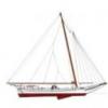 druxey got a reaction from acdblujns in Swan 42 by shipmodel - FINISHED - one-design racing yacht
Have you tried masking film and acrylic paint to simulate the non-skid areas?
-
druxey reacted to Dan Vadas in HMS Vulture 1776 by Dan Vadas - FINISHED - 1:48 scale - 16-gun Swan-class sloop from TFFM plans
Hi Aldo. I doubt if ANY pieces are the same shape/length because of the differences in the converging angles - theoretically they should be the same (or a mirror) for a particular piece on the port/starboard side.
Danny
-
-
-
druxey reacted to rekon54 in Le Fleuron 1729 by rekon54 - 1:24
hi
the stairs to go into the hold deposits, are still raw
rekon54
-
druxey reacted to garyshipwright in HMS Victory by guraus - scale 1:48 - plank on frame
Hello Alexandru. I know this has been brought up before but just some food for thought on the beakhead bulkhead raised platform. For me I don't think that Victory or other 90 to 100 gun ships had this platform. My reason are that plans of the Victory as well as others such as the Princess Royal of 1773,Ville de Paris of 1788, don't show this raised platform. My thinking is that the raised platform didn't come about on Victory till after they redid the bow turning it in to a round bow minius the whole beakhead itself. The upper deck went all the way fwd and was even with the main rail of the head work making ever thing on a even keel. There really was't any need for this small raised platform. Once the Victory bow was redone, as she looks today, it show's the beakhead buckhead, along with the raised platform. Do believe that some of the authors that has been posted,do not show the small platform because plans and other primary reseach doesn't show this. Here are some photo's of the plans I have of Victory going back to her first drawing which came from the Danish NMM. Also one from the English NMM and one out of Bugler book. One thing you will noticed is the primary plan doesn't show the small platform. You will also notice the plan of Victory with all of her carvings also doesn't show this small deck. It's not till you see the plan by Buglar that shows this. This might also explain why the round houses and collums go down two feet more. I have also added a photo of Alfred that does show the raised platform which was a common item on ships of 74 guns. It seems that if they had this raised platform it seems that primary plans would show this. If you look in Rob Napier book Legacy of a Ship model, on page 89, 90,91 and 92 how it shows the upper deck going all the way fwd and no small raised platform. Do hope that this is some food for thought on this small raised deck that raises a lot of question about did she or didn't she. Some food for thought sir.
Gary
-
druxey reacted to rekon54 in Le Fleuron 1729 by rekon54 - 1:24
good evening
advances Fleuron
rekon54
-
-
druxey reacted to Trussben in ECHO by Trussben - FINISHED - 1:48 - cross-section
Hi all,
Well if you don't know from my Confed build, I am now the proud owner of a bundle of Byrnes tools, I have the JimSaw, disc and thickness sanders to join my dewalt scroll saw.
I have been practicing and getting used to using them for the last few weeks and boy am I impressed.
Anyway this weekend I will be taking a break from painting and building the Confeds cannons and I am going to make another keel using the power tools and see which I think is better.
I will post pics of them both together when done.
Ben
-
druxey reacted to tlevine in HMS Atalanta 1775 by tlevine - FINISHED - 1:48 scale - from TFFM plans
I put in the centerline or king plank next. This plank is 3" thick and the lateral edges are beveled. My deck planking will be holly with one edge and end highlighted with pencil so the seams are more apparent. The hardest part of deck planking is determining the centerline. I drilled a hole in the midline of the stemson and inserted a pin into the hole. A doubled thread then is secured to the pin and to the #19 pillar to determine the midline. The thread is evident in the pictures.
The pins for the riding bitt, main topsail sheet bitt and the main jeer bitt were temporarily installed. The riding bitt extends all the way to the thickstuff over the floorhead. The other bitts end at the lower deck beams. These are 9" square but have an aft taper below the upper deck. The dimensions at the lower deck beam are 6"d x 9"w. The foot is rounded over. These are shown in TFFM as being bolted flush to the aft side of beams 11 and 12. The draughts for Atalanta show that they are mortised into the beams and that the jeer bitt is also mortised into the after hatch framing. These are (theoretically) bolted to the beams. In the pictures I made no attempt to check for plumb, as these were only temporarily fastened. During the construction of the lower deck framing, I did not think far enough ahead. I should have made these bitts and drilled the bolt holes as assemblies 11 and 12 were made. At this point, it would be next to impossible to put those holes in.
Of course, while I am taking pictures, Sadie decided that she was not getting enough attention. It looks like she is taking a bite out of the stern. In reality, she loves masking tape and the midline thread is secured with some (which she is trying to remove). Since we almost lost her to urosepsis last week (a really bad kidney infection that gave her blood poisoning in normal people talk), I guess I can tolerate some of her idiosyncrasies. But if she ate a piece of wood...
-
 druxey got a reaction from hamilton in colour of waterway
I've seen contemporary 18th century British models and the inner bulwarks are treated in many different ways. I've seen:
all red bulwarks and waterway (angled part only),
red bulwarks with unpainted waterway,
red quick work and black spirketting, unpainted waterway,
red bulkwarks with black waterway,
amongst other variations! Take your pick. In all cases the flat of the waterway is not painted.
-
 druxey got a reaction from augie in colour of waterway
I've seen contemporary 18th century British models and the inner bulwarks are treated in many different ways. I've seen:
all red bulwarks and waterway (angled part only),
red bulwarks with unpainted waterway,
red quick work and black spirketting, unpainted waterway,
red bulkwarks with black waterway,
amongst other variations! Take your pick. In all cases the flat of the waterway is not painted.
-
druxey reacted to wefalck in Zuiderzee-Botter by wefalck - FINISHED - Artitec - RESIN
I just noticed that when re-creating the building log from MSW 1.0 I missed out part of the work. Perhaps because it concerns some small and delicate parts that look simple, but are not so easy to manufacture at this scale.
Well, the smithy of the boatyard has been busy and turned out various pieces of ironwork for rigging and other purposes: The mast is held in its tabernacle by a latch hinging on eyebolts. Mast tabernacle There is a complex piece of ironwork that guides and holds down the running bowsprit (which will not be shown on the model, as it was normally left home during the winter season, when a reduced rig was used). The ring was turned from a piece of brass rod, while stay was fashioned from a piece of steel rod on both the lathe and the mill, as it has partially a square section. In fact, various parts of the ironwork do have square sections, inter alia to prevent them from turning, or because they have made from square bar, hammered to a round cross-section where needed. Bowsprit guide The leeboards are held by sort of square rings that slip over the leeboard-bollards. These rings were made from brass strips soldered together and filed to shape. The leeboard pivots on a bolt that is held by these rings. Various ironwork A major challenge were the various belaying and thole pins. On the prototype their maximum diameter is just under 40 mm, the cylindrical sections generally being around 20 mm. So, in the 1/90 scale this means they are 0.2 to 0.4 mm in diameter, with a length of 3 to 4 mm. There are five different types and the literature (VAN BEYLEN, 1995; DORLEIJN, 2001) gives the typical dimensions and shapes for each them. Turning them from the available brass was impossibe, so that 1 mm steel wire was used as starting material. Even then turning them flying, i.e. supported only in a collet in the headstock proved impossible. This lead to the design and manufacturing of a tailstock-held micro-steady. The spherical parts on the pins where shaped free-hand using files and strips of abrasive paper. Belaying pin Specially made micro fixed-steady for turning small slender items on the watchmakers lathe. wefalck -
druxey reacted to wefalck in Zuiderzee-Botter by wefalck - FINISHED - Artitec - RESIN
I am using a piece of thick cardboard on which I put the sail drawing. The whole then is wrapped in clingfilm, making sure no creases appear in the area of the sail(s).
wefalck
-
druxey reacted to Jeronimo in LE BONHOMME RICHARD by Jeronimo - FINISHED
3nd Construction stage
Main-Mast-Section
Project Planning;
Length of hull ; 499,0 mm
Hight of the keel to the top of the mainmast :1489,0 mm
Mainyard width including
Main-topmast studdingsail-boom : 729,0 mm
Complete rigging
Regards Karl
T e i l 26
-
druxey reacted to wefalck in Zuiderzee-Botter by wefalck - FINISHED - Artitec - RESIN
Continuation in small and sometimes tedious steps.
The sails were further completed by adding cringles and eyelets. For the cringles the sail was punched with a needle to simulate the eyelets. A piece of 8/0 yarn was threaded through, twisted with itself and secured with a blob of lacquer. The free ends were threaded cross-wise through the second eyelet and secured with knots. The cringle was secured with a bit of lacquer. For eyelets in the sail itself blobs of acrylic gel were set on both sides and once dry punched with a needle.
Sails ready to be painted
The foresail runs on small iron hoops along the forestay. These were reproduced by small rings of copper wire that were sewn to the cringles using 16/0 size yarn (Veevus, http://veevus.dk]http://veevus.dk).
Hoops of the foresails
There are various eyelets in the sail, e.g. for reefing points. These were immitated by a drop of acrylic gel medium glue on both sides of the sail that later was pierced with a needle.
The painted sails
The sails then were checked for any joints having come loose and more wood-filler was applied if needed. Now the sails were ready for painting. The original sails were tanned. Hence, a terracotta colour ('terre' by Prince August Air, http://www.prince-august.net) was chosen as the base colour that was applied with an airbrush. Once on the model some weathering and shading will add more plasticity. The eyelets etc. were ‚metallised’ by turning a soft lead pencil in them.
’Sailmaking’ tools
wefalck -
druxey reacted to wefalck in Zuiderzee-Botter by wefalck - FINISHED - Artitec - RESIN
The actual painting proceeded with Schminke-, Vallejo- und Prince August-Airbrush paints, but of course using very fine (10/0 and 5/0) brushes.
The painted skipper
But I had to fight with the brushes. The art materials department in the famous Bazaar de Hotel de Ville (BHV, www.bhv.fr) which has the best DIY department in Paris wasn’t the same anymore after a recent revamp. It turned out to be very difficult to find such fine brushes in Paris, but I needed to replace some worn out ones. Eventually I ordered some via ebay in Germany. Their rather fat three-sided handles looked as if they would be very comfortable, but their turned out to be really ‚rat-tails’. I gather you get what you pay for. Also: one should really try the point in the shop, which is obviously not possible when ordering through mail.
The back of the painted skipper
The painting technique was largely the same as for bigger figurines. However, at the 1/90 scale one needs to simplify, particularly when painting the faces. Thus, the eyes were indicated only by the shadows beneath the eyebrows. This I learned from Canaletto, who was able to render a very lifely population in his Venice pictures with just a few strokes of his brush. The effect is calculated form normal reading distance – on your computer screen the 18 mm high figures appear several times magnified. Painting the faces in acrylics was an experiment. The open time of these paints is just too short for painting soft transitions and I will return to artist’s oils for this.
The painted mate.
Photographs show you the coarseness of your work glaringly. Observed from normal reading distance, I believe, the figures look quite convincing.
The painted mate from the back.
The scenic setting will be eventually populated by a boy belonging to the botter, a Volendam couple enjoying a walk on the dike and another couple, where he is pushing her in a sledge on the ice.
wefalck -
druxey reacted to wefalck in Zuiderzee-Botter by wefalck - FINISHED - Artitec - RESIN
The work on the model is frequently being interrupted by travels and other activities, e.g. working up the pictures taken during my travels.
It continued with the painting. The actual painting is a rather complex procedure and I have not documented all intermediary steps.
The first step after the base-coat was to apply a coat of nitrocellulose-based wood varnish in oak. The idea was to simulate to some extend the surface treatment of the real wood, though with somewhat different materials, in order to create ‚depth’ of the wood surface. I used this method successfully in the past on small parts. Here, however, the problem arose that a second coat or touching up would dissolve the first coat. On the next model I will apply the varnish by airbrush or use an acrylic varnish.
The varnish was cautiously matted with steelwool and a glas-eraser pen. Then the wale and the registration board were painted in black acrylic. The registration number was painted freehand in white acrylic. The next step then was a juidicious weathering/washing in burnt umber acrylic to simulate the surface treatment with Stockholm tar. In order to simulate the coal-tarred underwater body burnt umber was applied in more covering layers.
Individual parts, such as the spars, the leeboards, the rudder etc. were treated in a similar way. In oder to achieve a uniform degree of matt-ness, everything was coated lightly with the airbrush in Winsor&Newton matte acrylic varnish.
White, beige and black pastels were applied with a brush and Q-tips to simulate grime and salt. The quarter deck and floorboards also attain in this way a nice greyish worn appearance.
The various ‚ironwork’ received a base-coat in black acrylic with the airbrush. Then a mixture of ‚metallic rust’ (Prince-August Air/Vallejo) and burnt umber was then applied with a brush. The parts thus receive a certain patina – in real life they were painted black, painted in lineseed-oil or left bright. On places were the ironwork would have been bright from use a soft pencil (6B) was rubbed, which results in a subtle metallic sheen.
wefalck -
druxey reacted to amateur in Zuiderzee-Botter by wefalck - FINISHED - Artitec - RESIN
Ofcourse they are not the same: why use tow names for the same ship (more often in Dutch, different ships share a common name)
Botters are fishing ships (see-going, originating from the southers parts of the former Zuiderzee)
Boeiers were originally small freightships, in later years (i.e. from the 18th century onwards) mostly build as yachts.
However, the shiptype called boeier did evolve quite a bit, as can be seen in this 17the century picture.....
Different rig, different hull, different everything.
Still: same name.....
Jan