


rlb
-
Posts
651 -
Joined
-
Last visited
Content Type
Profiles
Forums
Gallery
Events
Posts posted by rlb
-
-
Thanks, John!
Welcome aboard, B.E., and thank you for your kind words.
Ron
-
I think I'll pass on those oysters, but Rocky Mountain Lobsters...isn't that a baseball team?
Ron
-
Nice work, Russ.
It seems we are ever learning about the authentic ship building practices, as our interest and our reference materials expand (not to mention MSW itself!!).
Our guesses sometimes come back to haunt us, but this is a handsom model, and thanks for sharing it.
Ron
-
I spent the day today re-making two chesstrees.
Here's the Chapelle drawing, and I based my first chesstree and it's location on this--
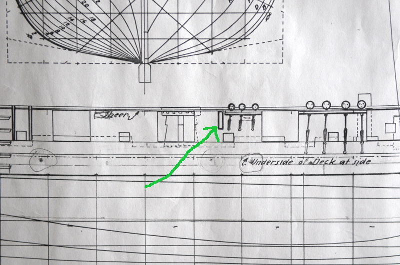
However, it's location doesn't quite work because Chapelle's chainplates aren't long enough. They don't include the topgallant and royal backstays. Corrected chainplates will move the chesstree aft.
Since they had to be moved I removed the old chesstrees, and decided to remake them in a more typical shape.
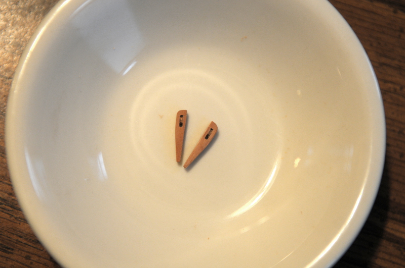
Old one on the left, new one on the right--
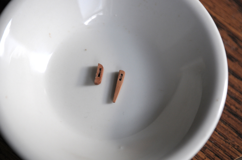
Here are the new chesstrees. In the first picture the piece on the left is in it's rough, beginning form--

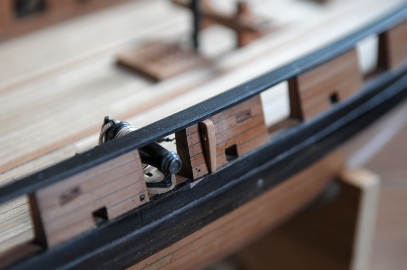
And here they are test fitted on the hull. They need finish applied, and I'll wait and glue them on when I get to the chainplates themselves--

Just forward of the new chesstree you can see the "scar" where the old one was removed--
Ron
-
-
Thanks, John.
No time wasted--
With all the cleats installed, not much room to get in there--
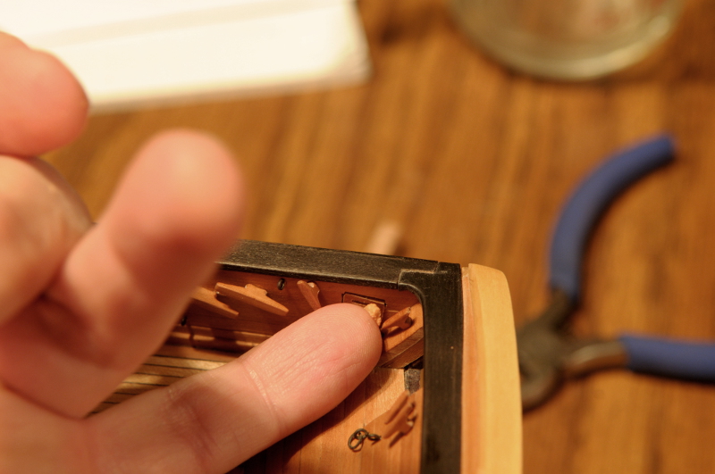
Not perfect, but better--
Ron
- themadchemist, CiscoH, avsjerome2003 and 1 other
-
 4
4
-
Slow progress.
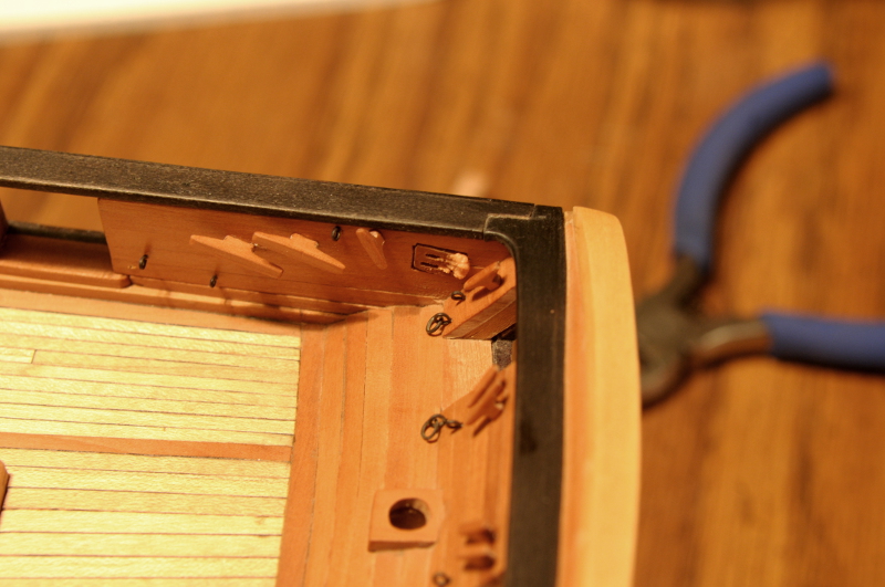
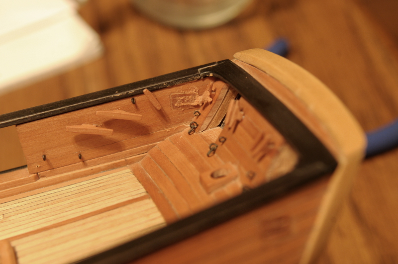
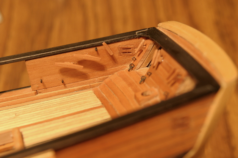
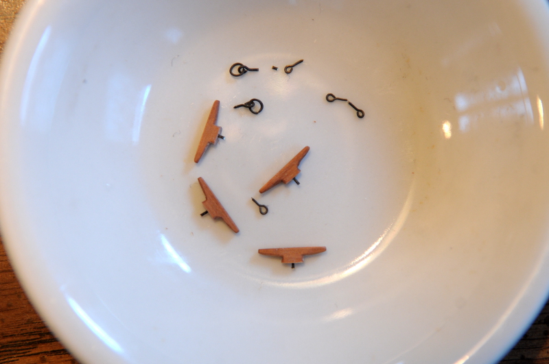
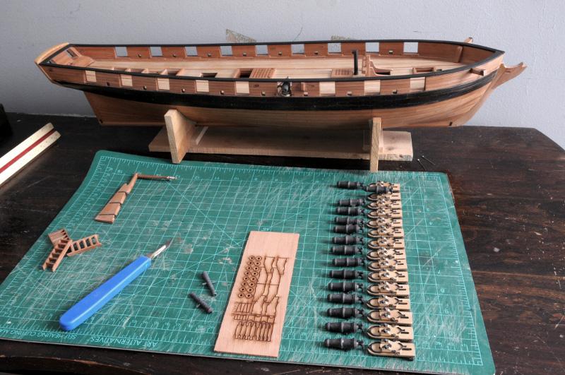
Here's a selection of pieces to be glued on: eybolts, eyebolts and eyebolts-with-rings for the transom gunports; some cleats for the running rigging--
And here they are glued in--
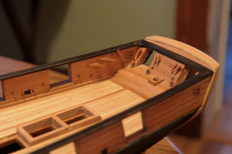
That double sheave piece poorly cut into the bulwark is bothering me. It doesn't stand out so much in plain eyesight, but I think I'll try putting some sawdust paste in the gaps.
Ron
-
Thanks, Christian! Yes, my thought from the start has been to rig her, but without sails. It's a little foolish, though. Just the hull I could find a place to display, but I don't think have any where to put a rigged model of this size, especially considering the case it will need. So we'll see.
Ron
-
John,
Yes, all wood has been from the Lumberyard. Most came along with the original purchase of the kit, but due to a few goof ups on my part, and some changes I wanted to make, I bought some extra billets of Swiss Pear.
Ron
-
Thanks, Steven!
I was hoping to get at least a small update posted today. The cleats are ready, but I've been poring over Chuck's Syren rigging plans (a similar brig), trying to wrap my head around all that needs to be prepared for the rigging--taking into account some differences between the two ships, and trying to make sure I know where to install everything that needs to be installed. It's overwhelming! I hope to have some progress to show this weekend.
Ron
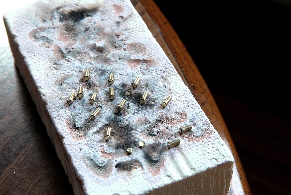
-
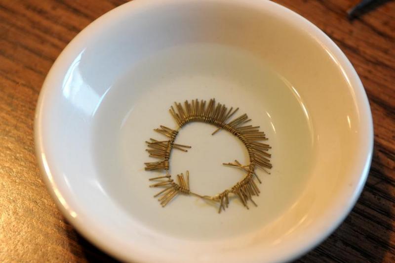
A small update:
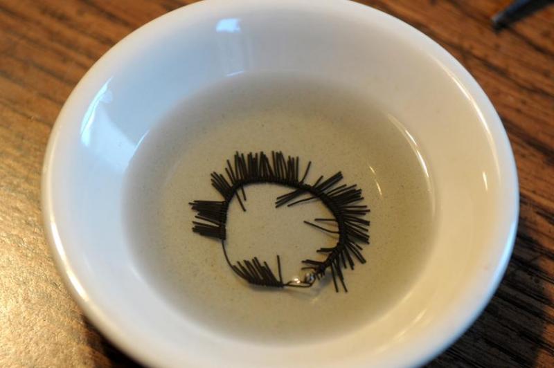
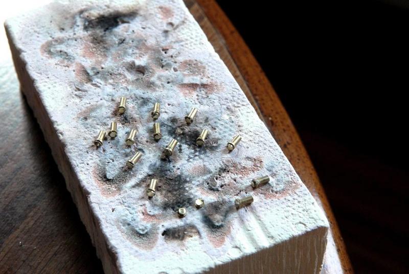
About a 80 new ringbolts in the soup to be blackened--
Drilling holes for pins to strengthen the cleat attachments--

Eight large cleats, and about 16 small ones just about ready--

One thing I noticed in reposting all the old log photos--my green cutting mat has gone through some changes!!
Ron
- CiscoH, BETAQDAVE and themadchemist
-
3
-
Ilhan, your work is not only precise, but it's also very beautiful. I just noticed those short curved planks on the forcastle, very nice work.
Ron
-
Thanks, Brian, Sinan, and Patrick!
Just a few more words on those small plates--I only plan to do them for the breeching rope bolts, though the Niagara replica also has them for the outhaul tackle bolts. And I'm cheating, my bolts don't go all the way through the bulwarks. That would make them much, much harder to install!
The pieces are blackened, and we'll see them again when I glue the rest to the hull. I'll try to take a close-up photo then.
Ron
-
Hi Amfibius,
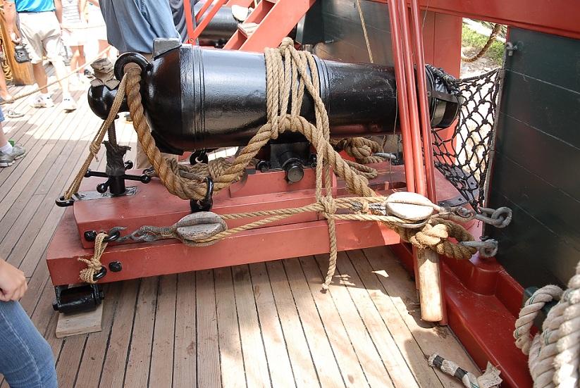
Here's a picture of the Niagara replica which shows what I was copying--
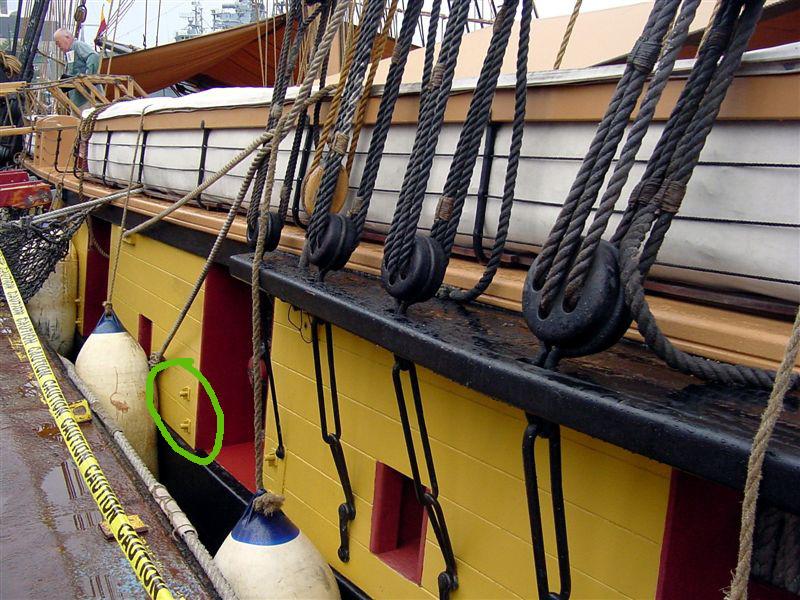
The ringbolt that secures the carronade breeching rope on the inside, extends through the bulwark, and has this small plate and a wedgepin (which is marginally visible) to prevent it from pulling out when the carronade recoils. I've read of people going to the trouble of making the tiny locking wedgepin!, but I haven't done that.
I hope this explanation helps.
I used a fine tooth small hand saw, and a file, to make the scarph joints, and no, I do not own a scroll saw!
Ron
- BETAQDAVE and garyshipwright
-
2
-
-
Looking good, Craig! From what l've seen of others' Berry builds this is challenging framing. Looks like you've got it under control.
Ron
-
March 5, 2010
The flashback is over--that's everything I've got from MSW 1.0, and we are back to real time with this post. I've been picking away at the bulwark cleats, and will be gluing them in place, along with the rest of the carronade tackle eyebolts, soon.
Ron
-
February 2013
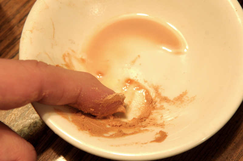
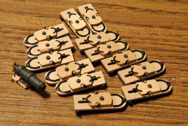
In the days leading up to the great crash, work and experiments were done on the armament--
One of the long six pounder carriages was assembled, though not yet complete--
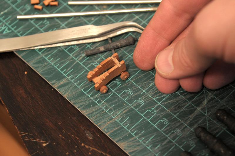
And a blackening glaze using surplus ebony wood stain was tried (with success) on the "greyish" metal guns--
Then more than the guns went dark for a few agonizing days.
Ron
- BETAQDAVE, garyshipwright, dafi and 2 others
-
5
-
January 2013
Work to finish the transom was undertaken.
The Chapelle drawing--
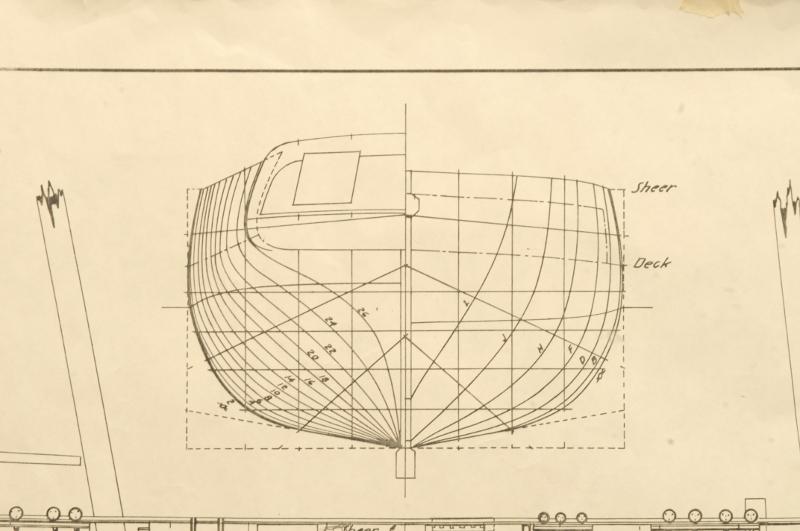
Possible variations given my particular situation with the transom--
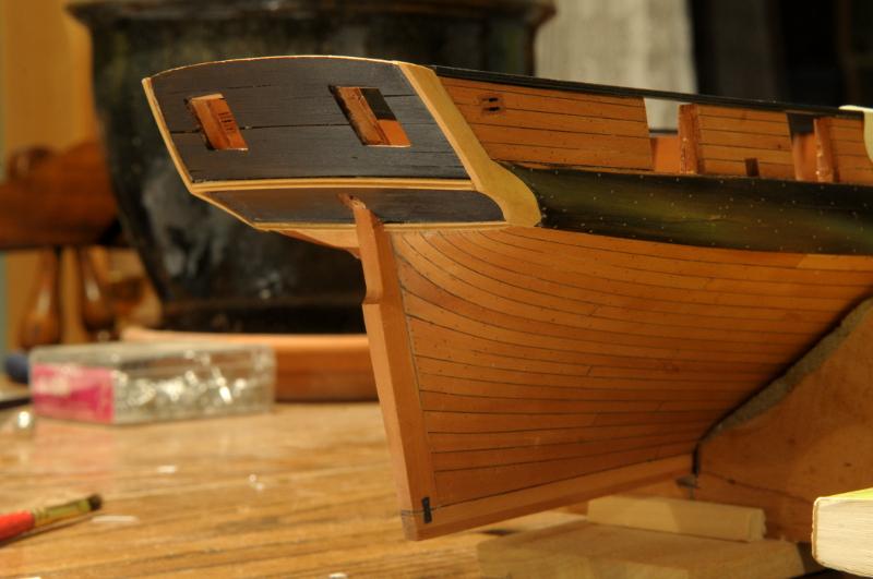
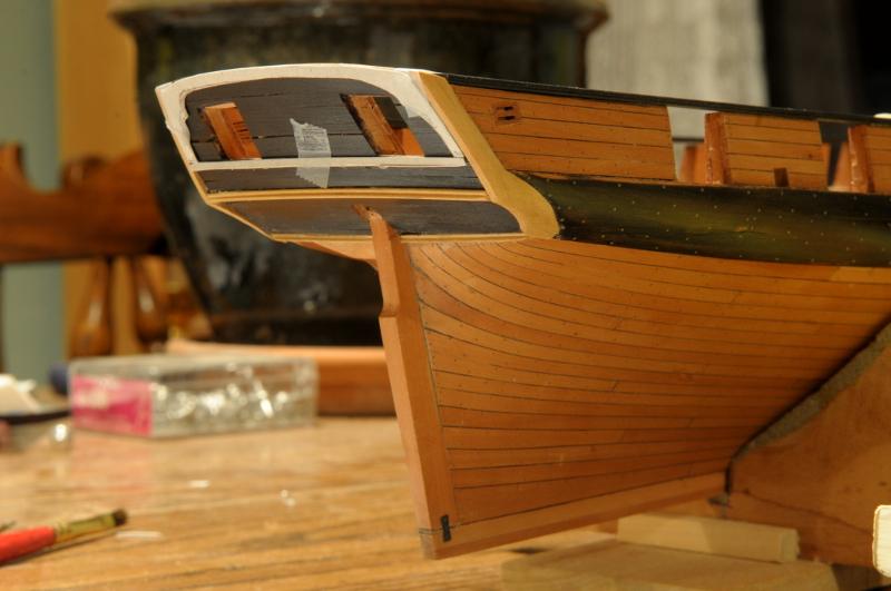
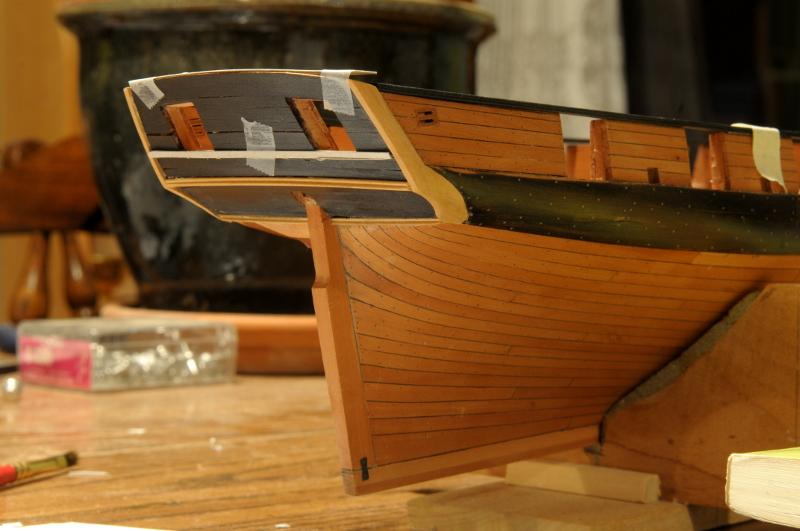
The least decorative seemed most in keeping with the era of the ship, and the current state of the transom.
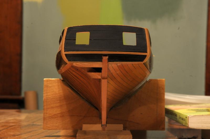
The transom framing needed to be cut down where it raised above the bulwarks--
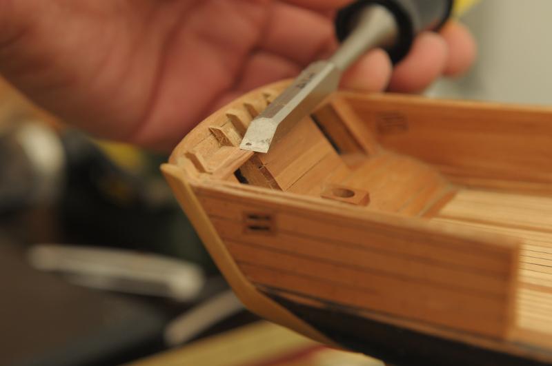
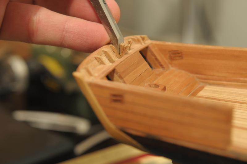
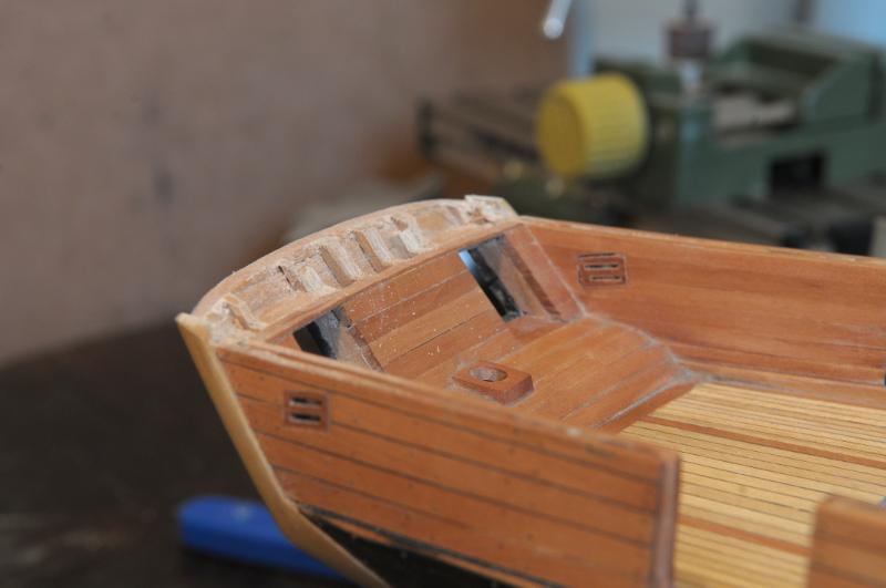
A very tricky top trim piece was carved from boxwood--


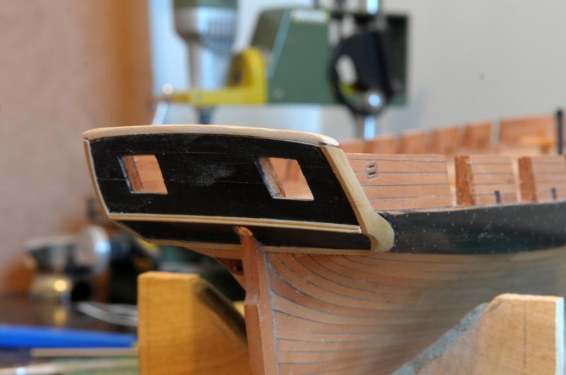

Finally, the stern portion of the cap rail is fitted, and stained--

Ron
- themadchemist, CiscoH and BETAQDAVE
-
3
-
Hey, Robbyn,
You're the brave soul persevering through all the ups and downs to finish your build. I believe you'll know at the end how much to bite off for the next one!!
Best,
Ron
-
January 2013
As a result of a New Year's Resolution (which is looking like it will be the most sucessful one I've ever made!) work was begun again.
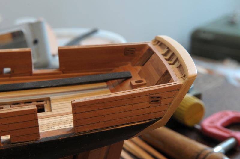
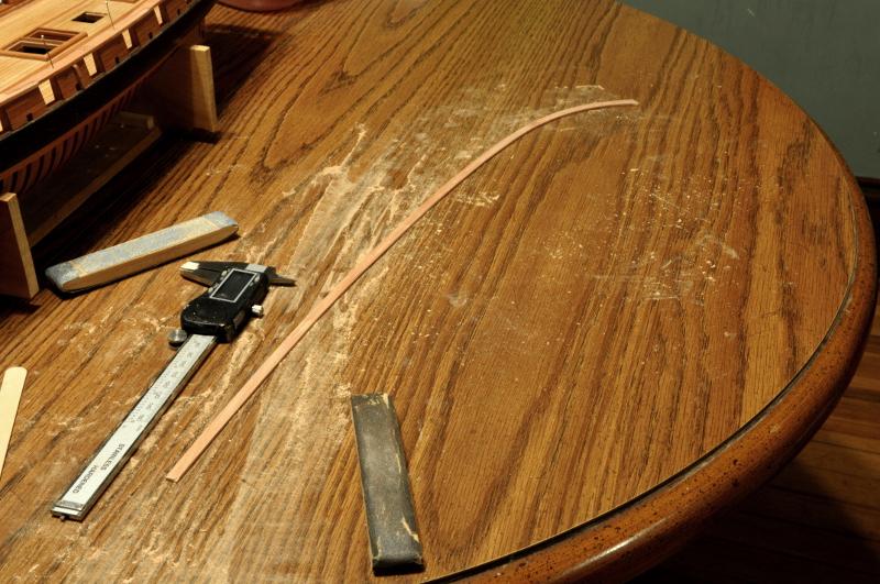
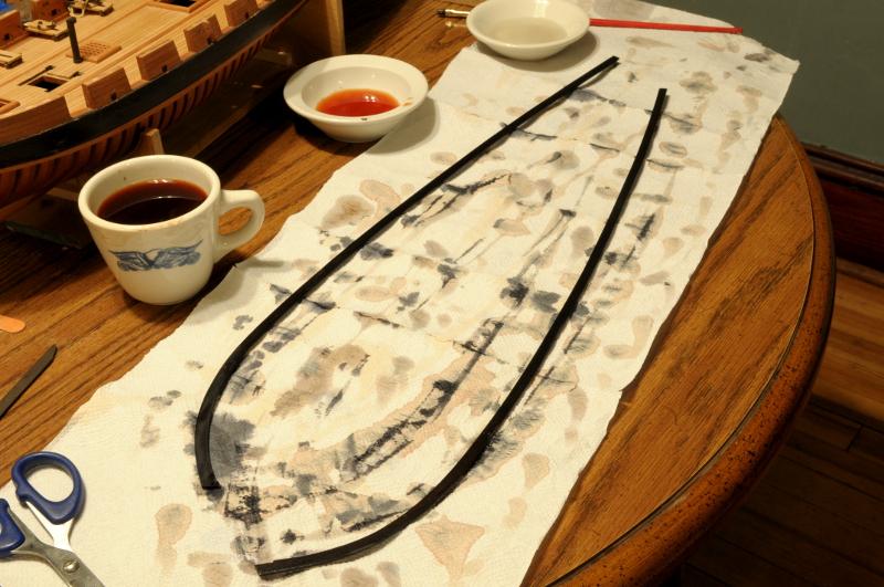
The first order of work was the cap rail--
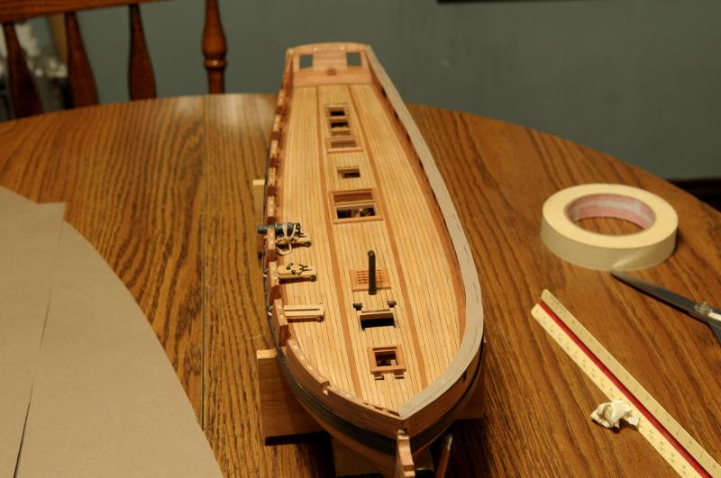
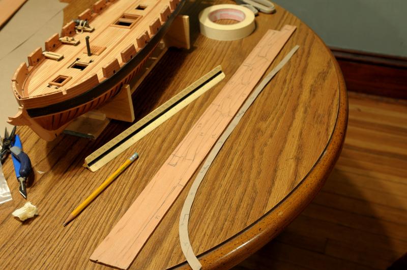
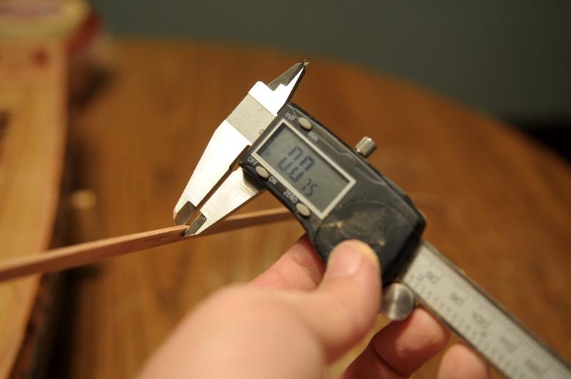
The stock I had was too thick, which required sanding the pieces down quite a bit. Deja Vu with the hull frames. The pear for the cap rail is much harder than the cherry of the frames, and this work took frustratingly long. Oh, for a thickness sander!--
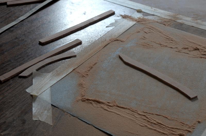
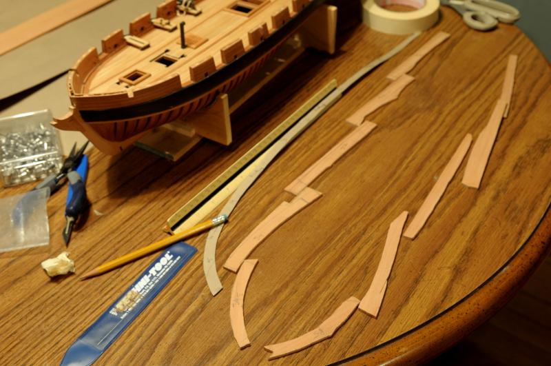
Sanding to shape, and cutting scarph joints--
After cutting all the scarph joints, the pieces were glued together--
Sanded again and checked for thickness--
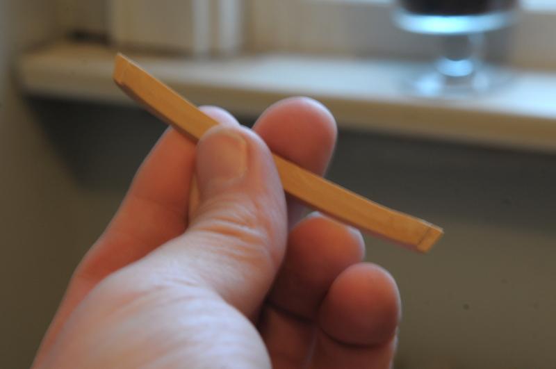
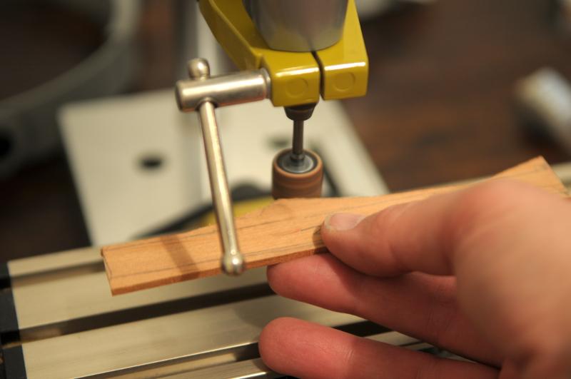
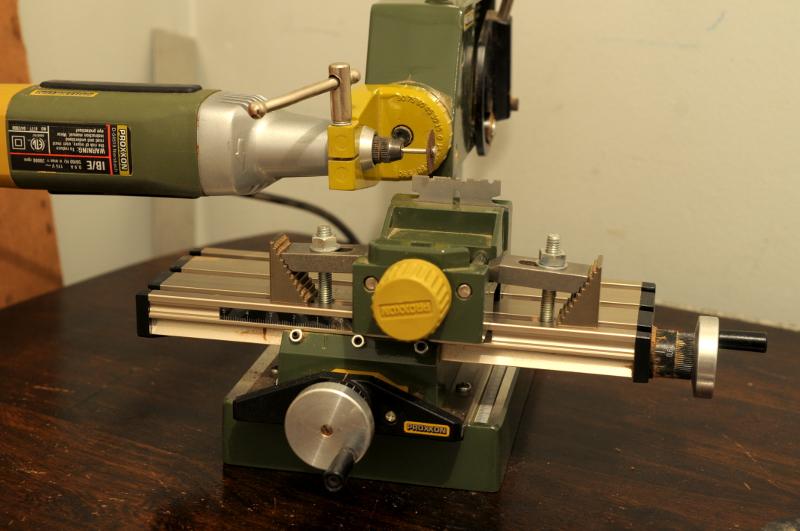
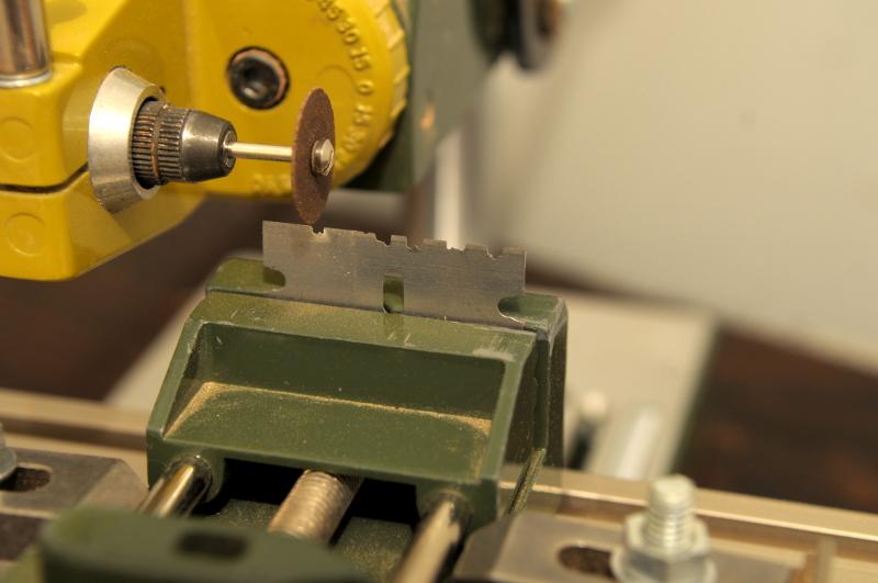
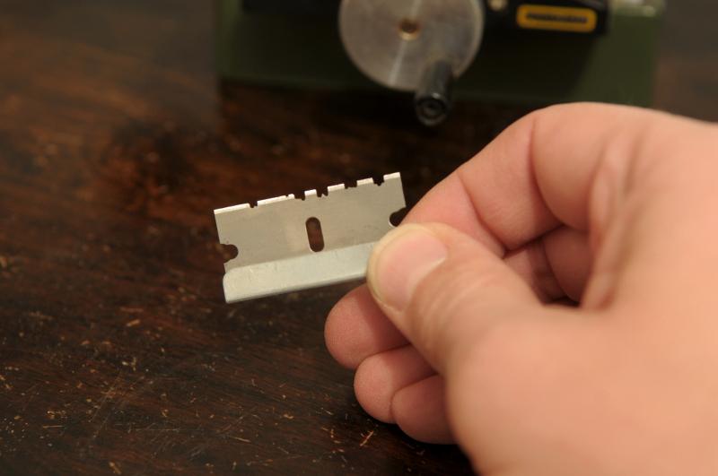
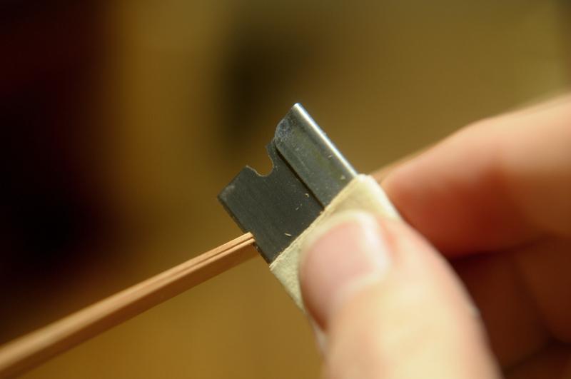
A razor blade was ground to scrape a profile into the cap rail--
The profile used for this particular purpose is the one on the left--
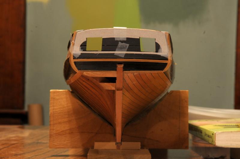
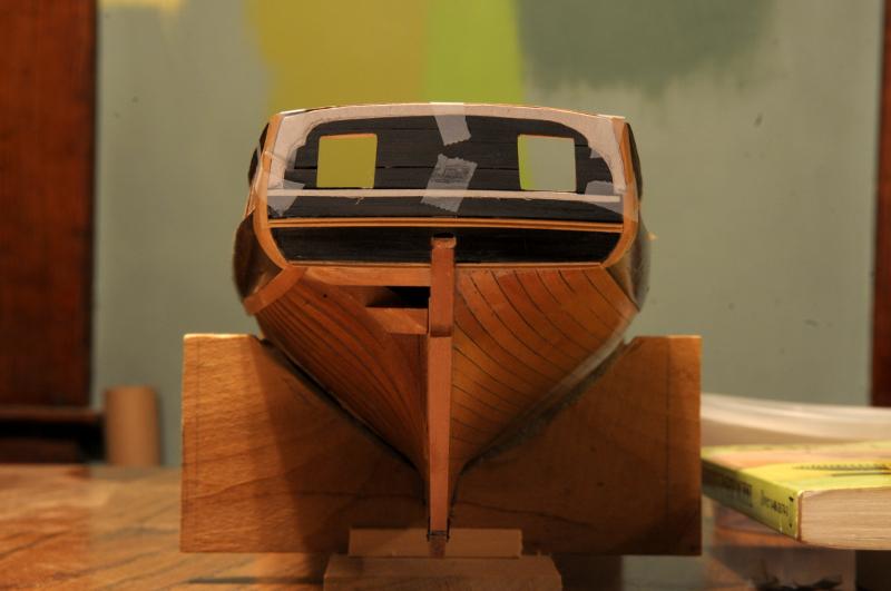
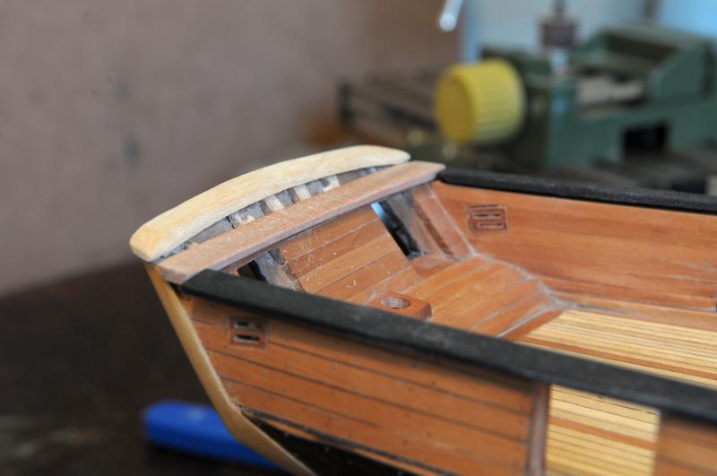
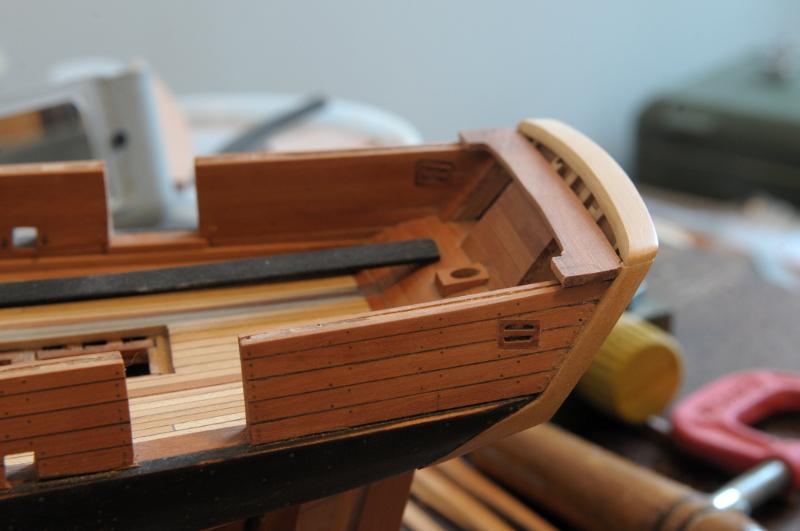
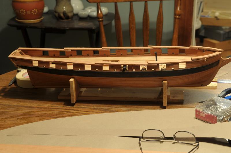
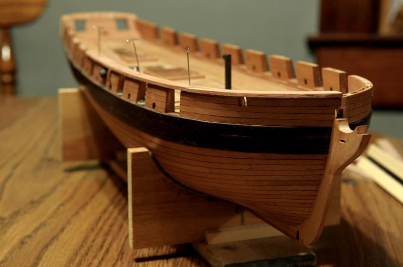
The rails are test fitted to the bulwarks--
Now experiments are done to test whether the rails should be left natural, or stained black--
This was a tough choice. I really believe both ways look good. I decided to go with black rails, since that is what was originally in my imagination, and what I've also seen on a lot of other models--
Ron
- BETAQDAVE, themadchemist, dafi and 2 others
-
5
-
-
July 2011
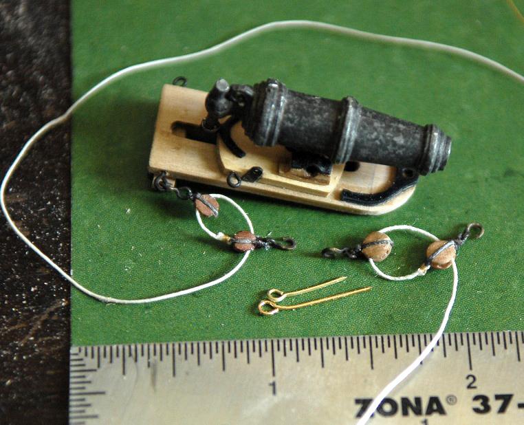
Experiments and work was done for the carronade completion and rigging.
Comparison of 3mm and 4mm blocks, 3m was chosen--

Test rigging--

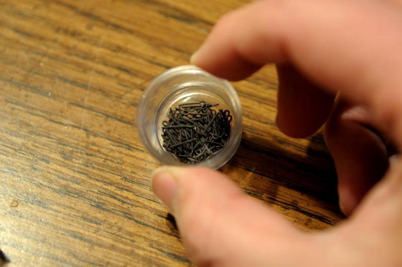
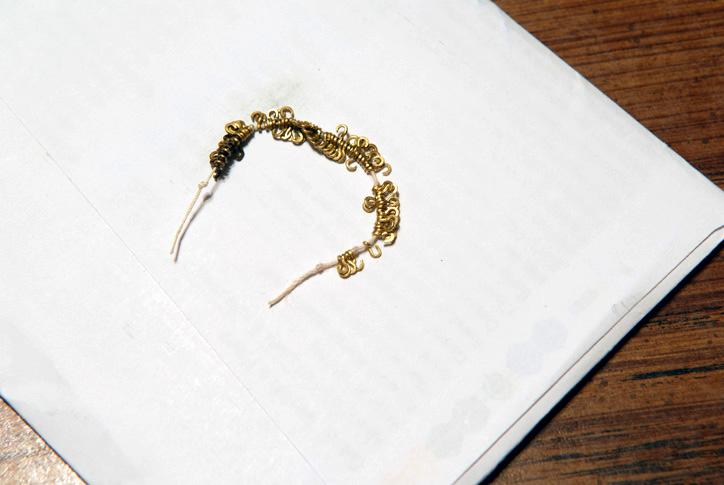
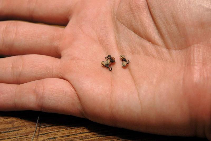
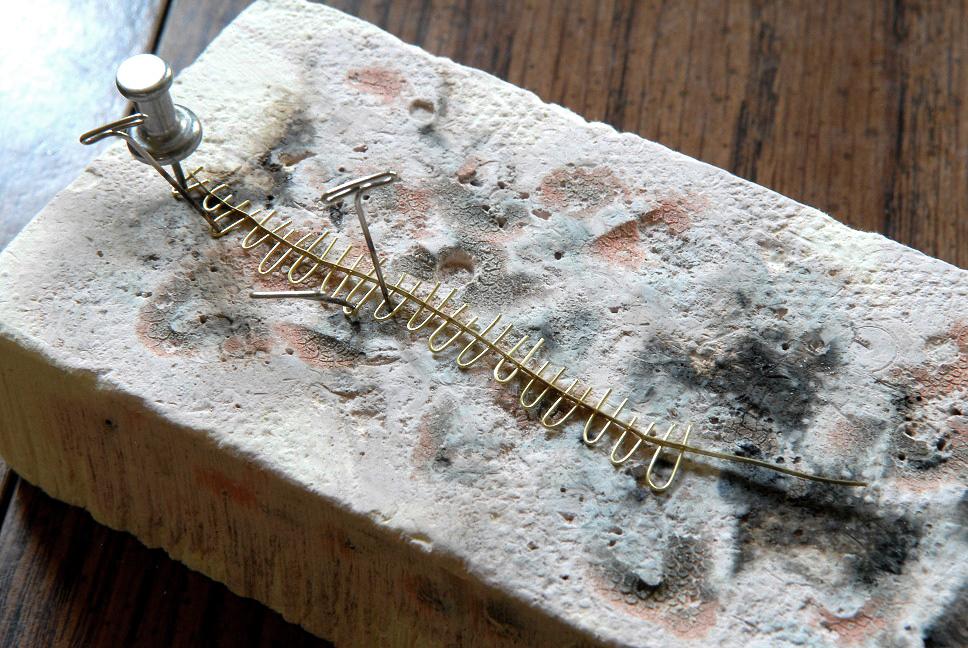
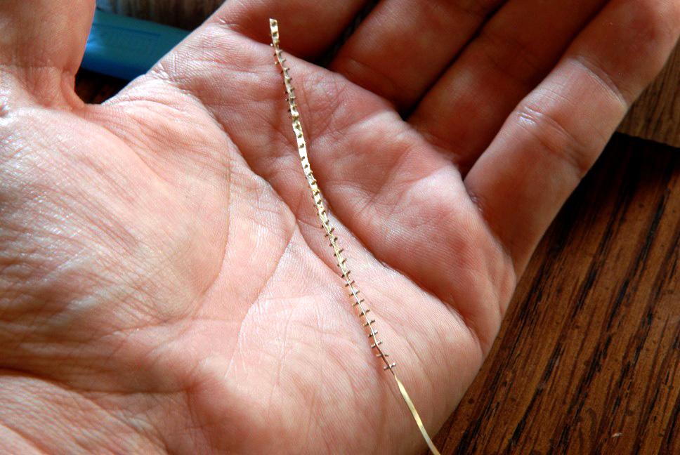
The hooks seemed too big, making it difficult to draw the tackle tight enough, so I made an attempt at making them smaller--
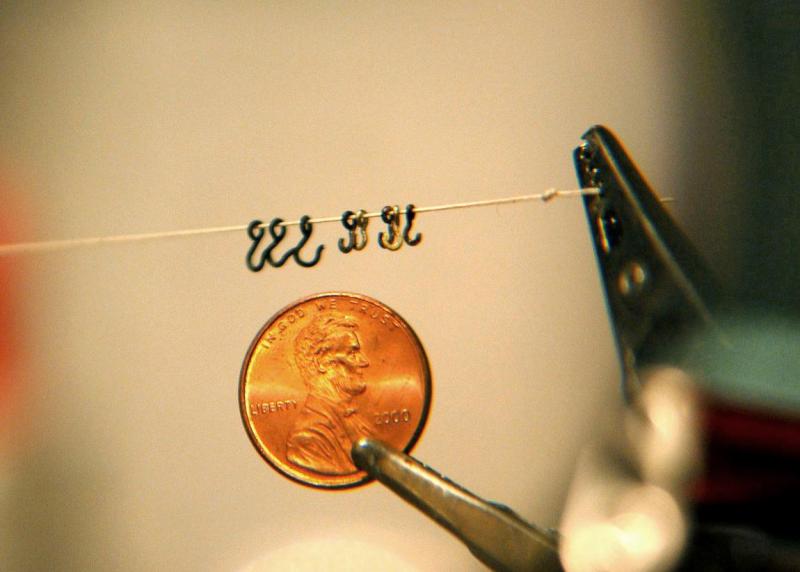
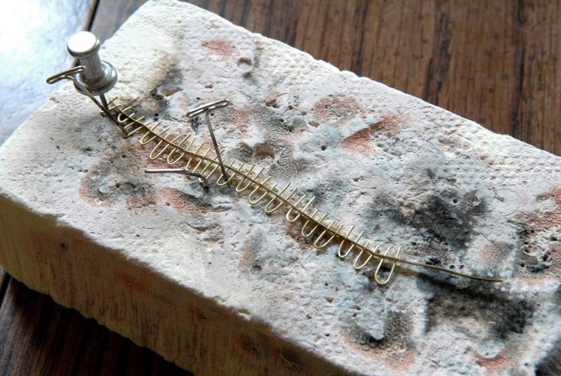
This was successful, thanks in large measure to my new magifying headgear, but it meant that a minimum of 72 new hooks would need to be made--
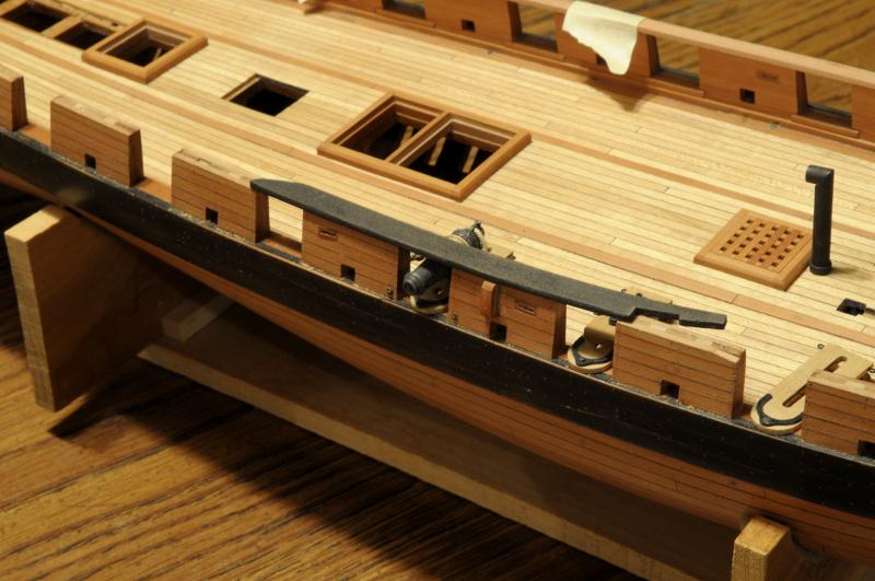
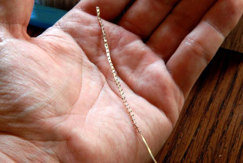
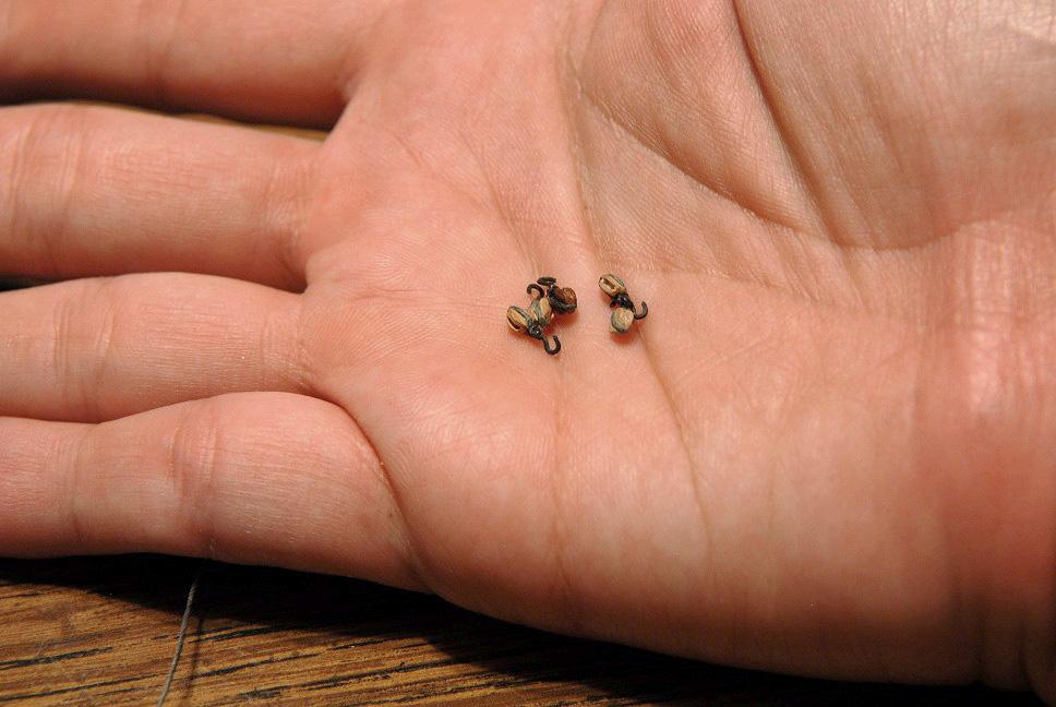
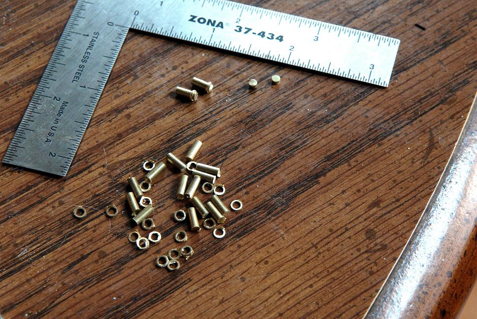
On the outer bulwarks, the fastening of the eyebolt shows, so a method was devised to make these tiny pieces--
A few blocks were stropped with the new hooks--
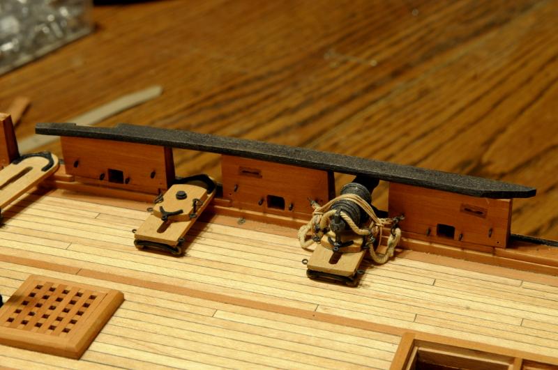
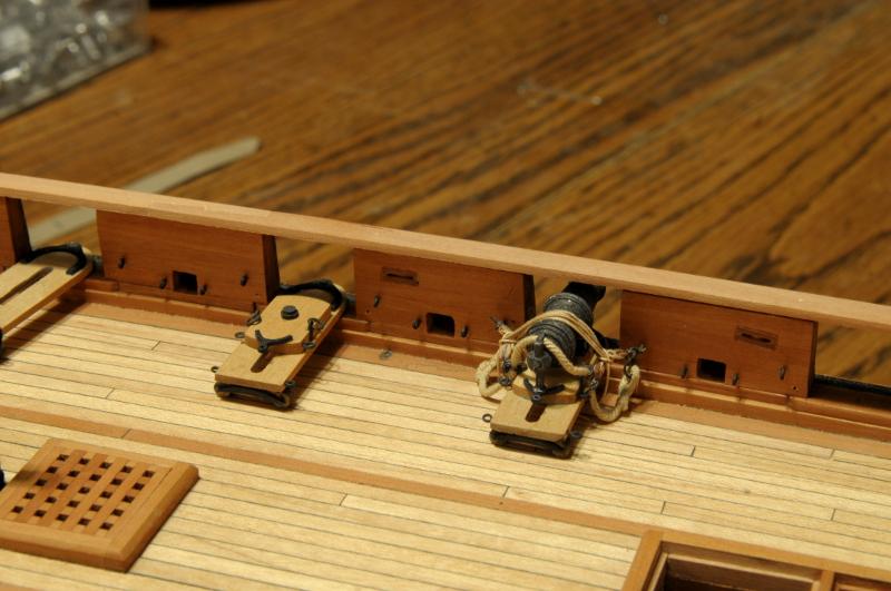
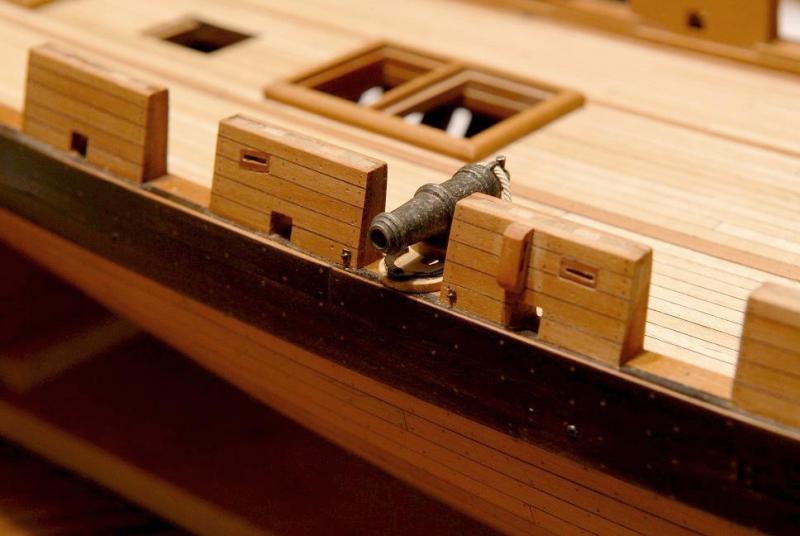
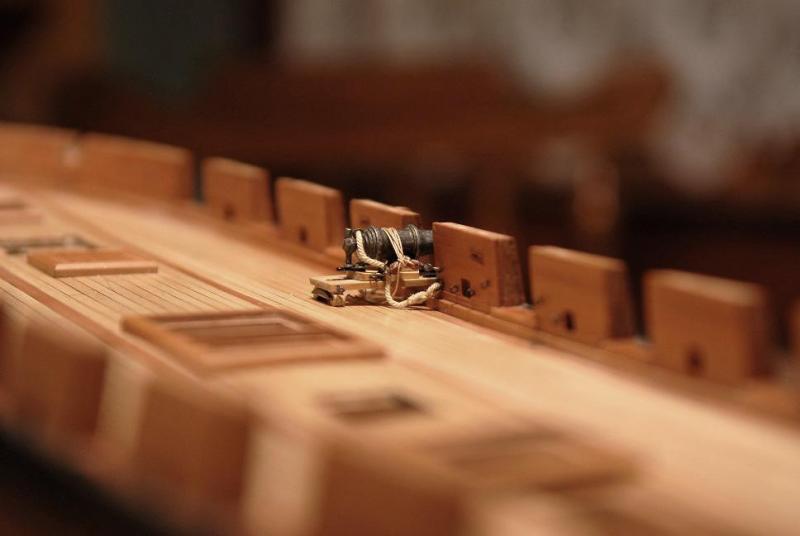
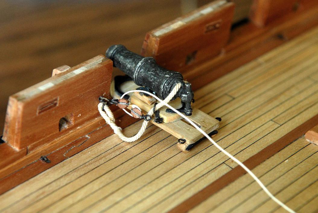
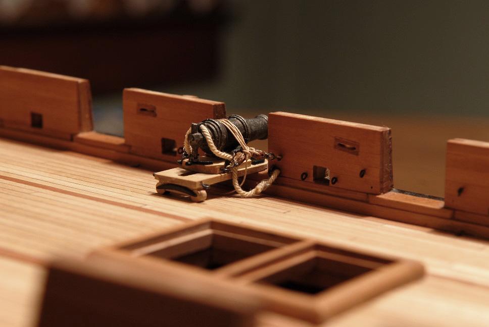
Looking for an alternative to leaving coils of rope on the deck, I thought I'd try trussing the carronades as I'd seen them on the Niagara replica--

I altered it to put my guns in the run out position. This probably makes it unrealistic in the actual practice sense, but I prefer it visually (modeler's license!)--
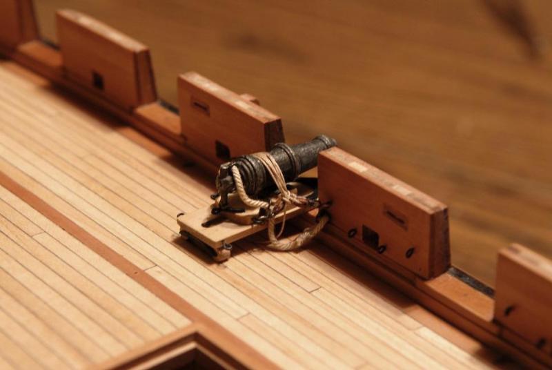
I liked the way it came out, so will do this when the guns are eventually permanently mounted on the ship--

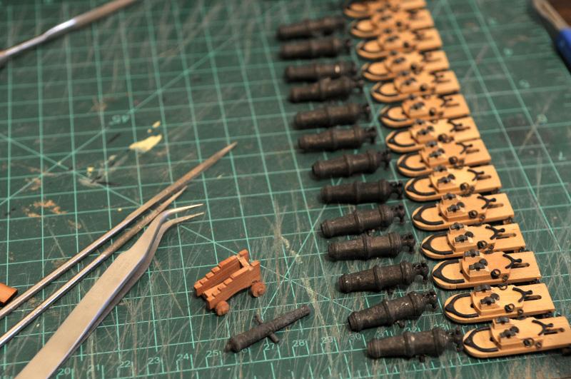
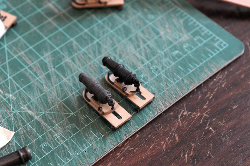
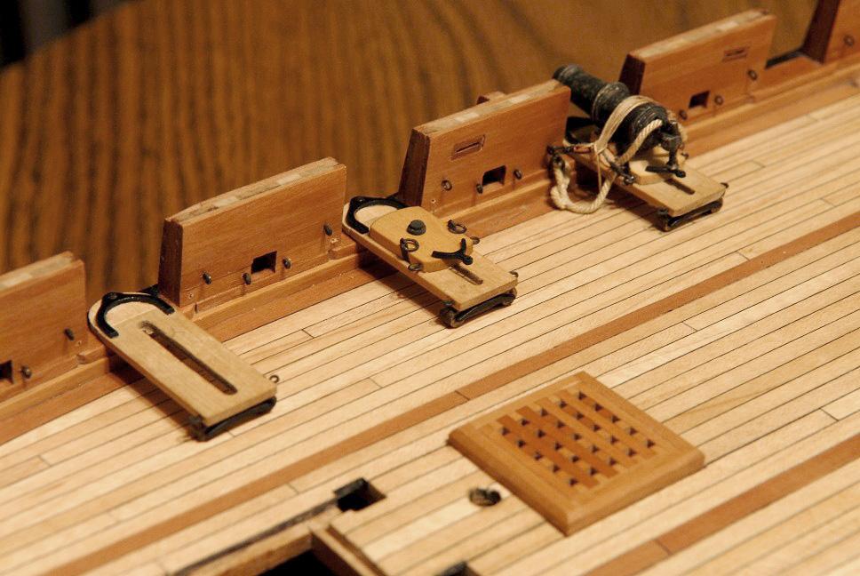
More work needed to be done to complete the carronade carriages-

Making the iron "slide pins" (my own name)--

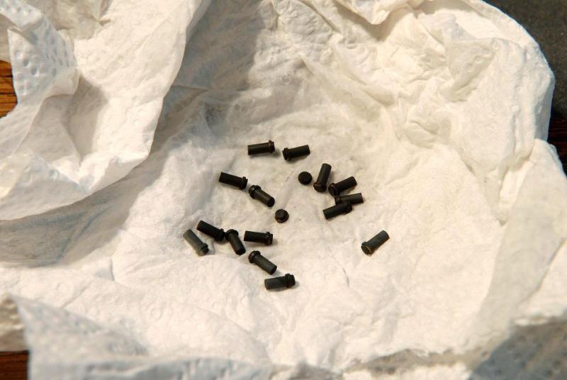
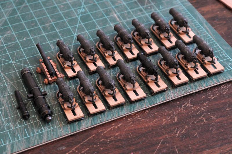
Various iron attached to all the carriages--
Here are three carronades shown various degrees of completion--

Ron
- CiscoH, BETAQDAVE, garyshipwright and 2 others
-
5
-
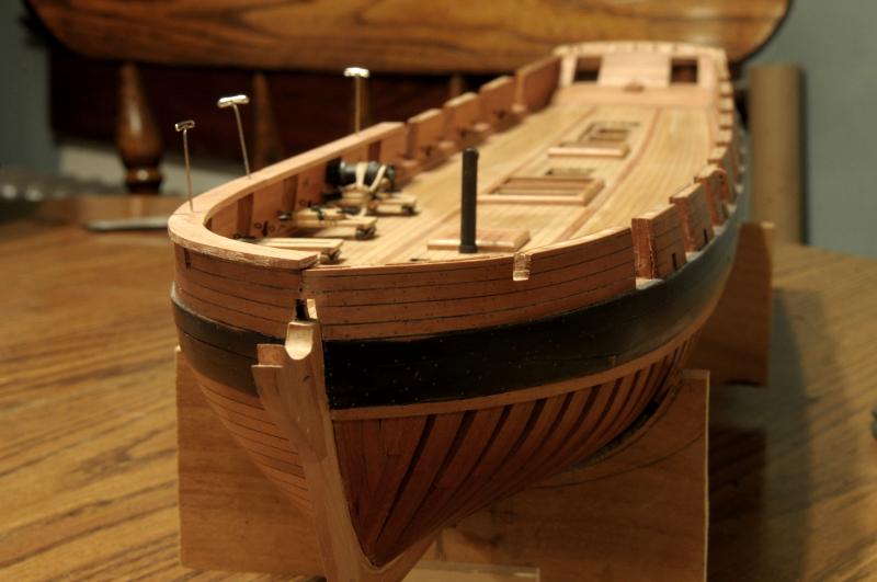
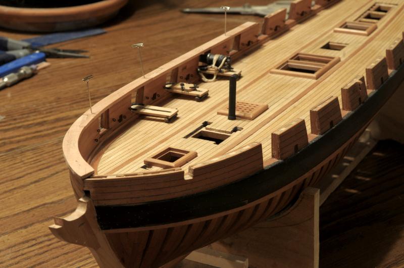
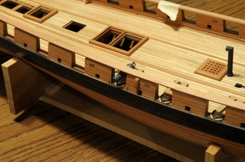
July 2011
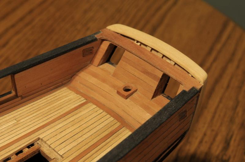
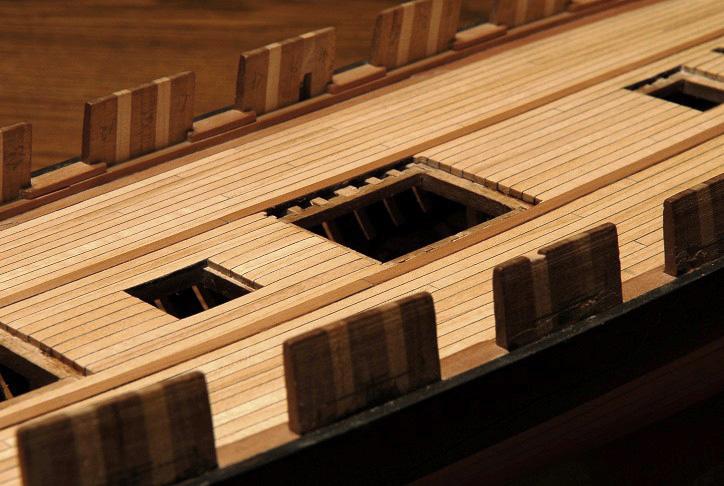
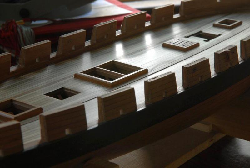
Deck Adjustment:
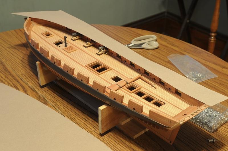
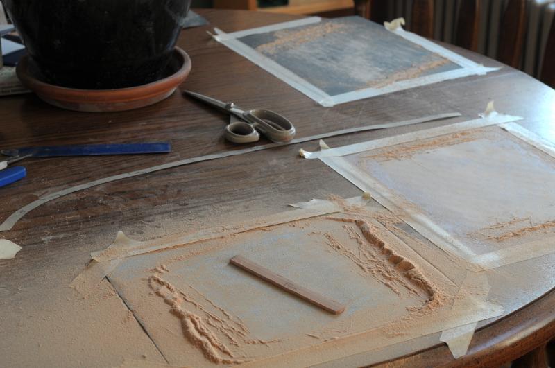
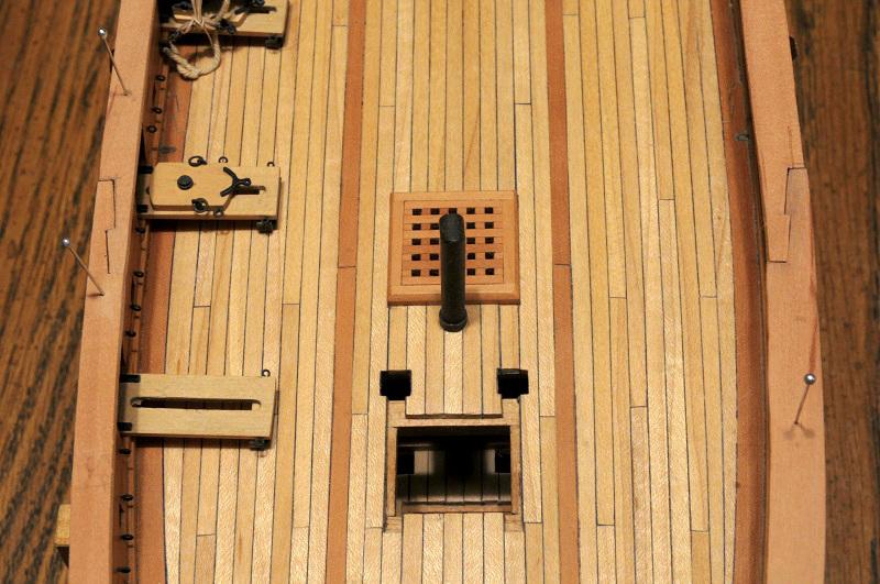
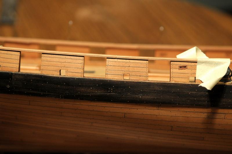
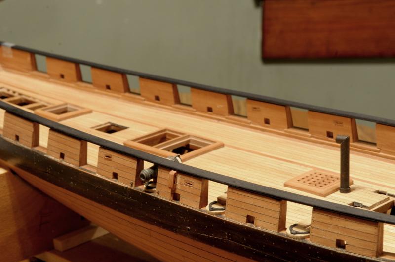
A correction to the deck planking was made, after I realized that instead of just the binding strakes sitting proud of the rest of the deck planking, all the planking in-between the binding strakes should also be at the raised height (about an inch).
This meant sanding down all the planking outboard of the binding strakes, and sanding the binding strakes down to the level of the center planking.
First picture is "before", though it's hard to see that the binding strake is indeed higher than the center planking. It's actually easier to see this on older pictures in the log--
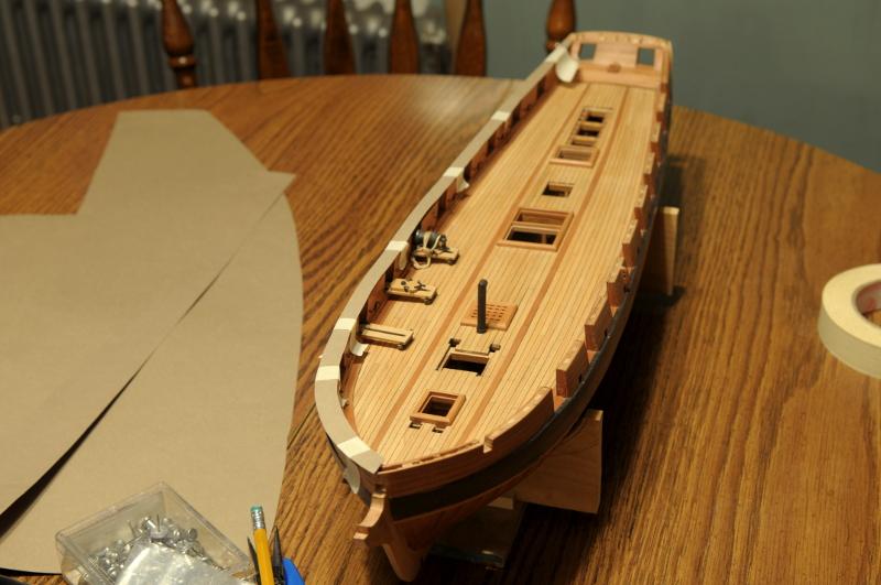
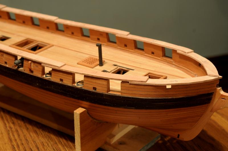
After--
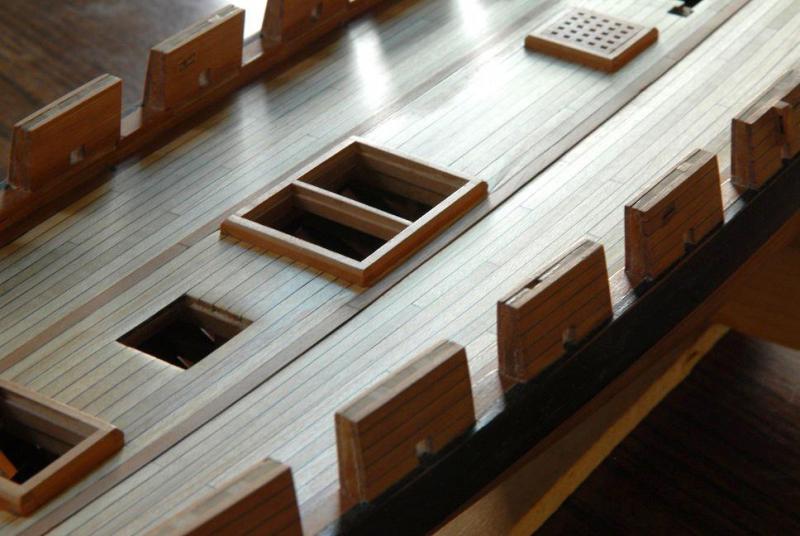
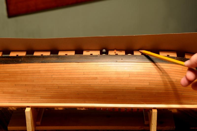
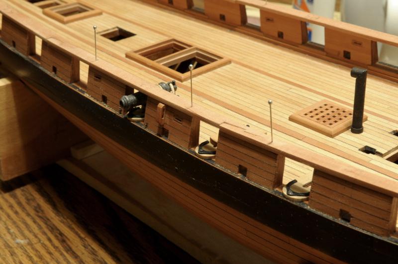
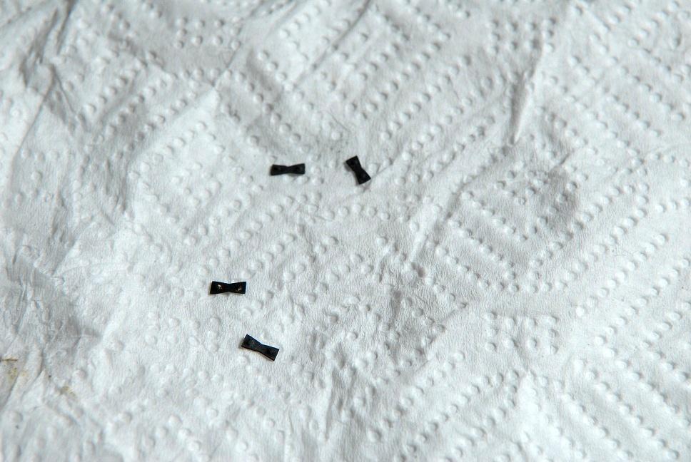
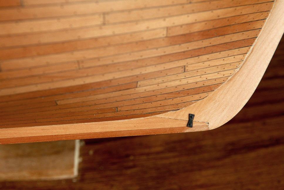
Fishplates:
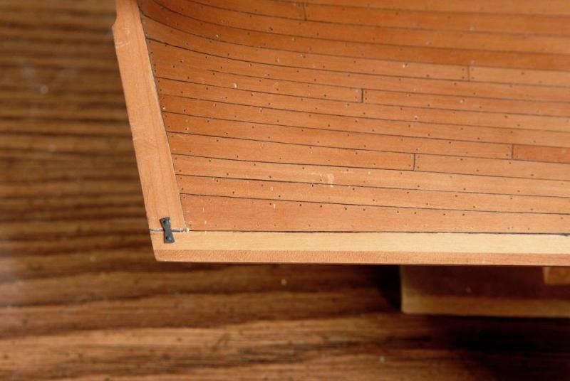
The "bow-tie" shaped iron that helps hold the back-bone together--
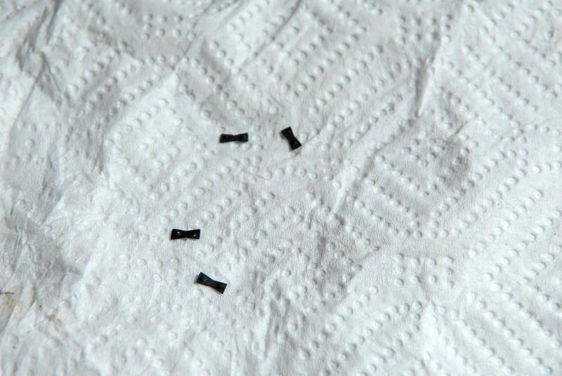
You can barely see in this photo, I have also added a "stop-water" dowel at the joint of the keel and stem.

I have a stop-water here also, but it's harder to make out--
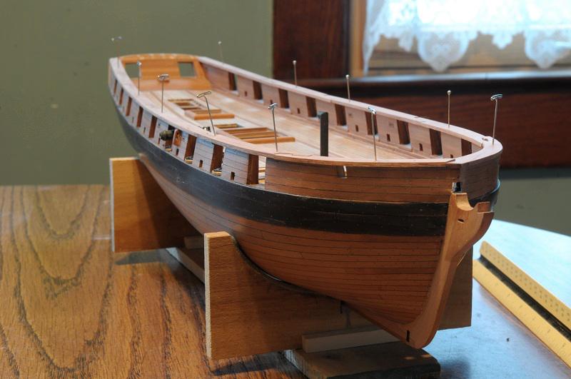
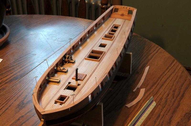
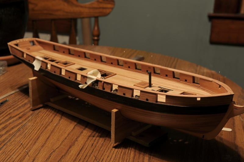
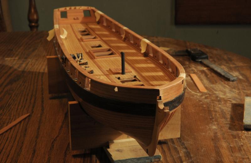
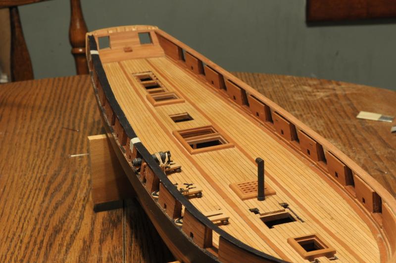
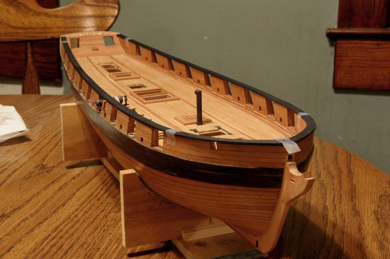
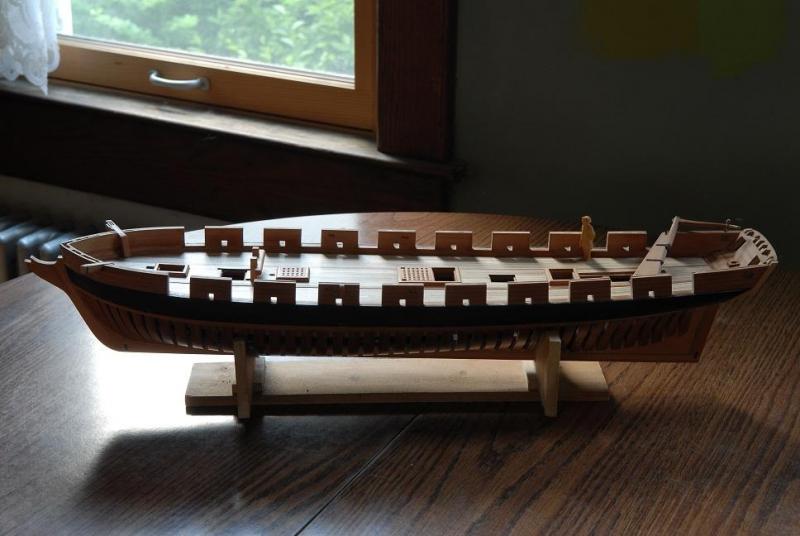
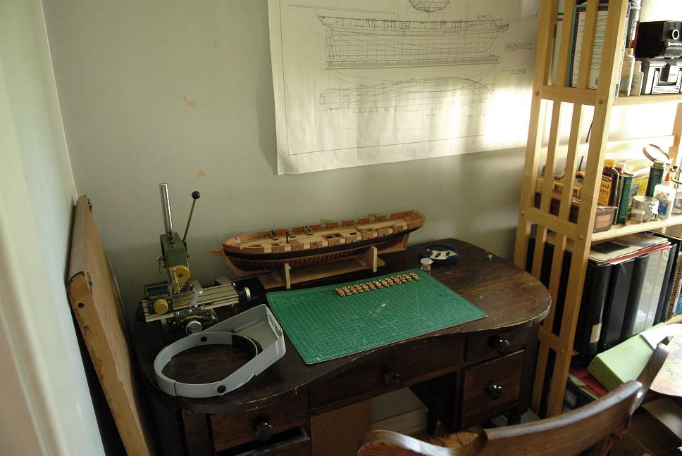
A nice overall shot of the progress at this point--
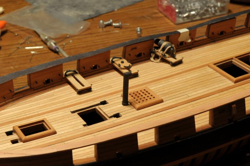
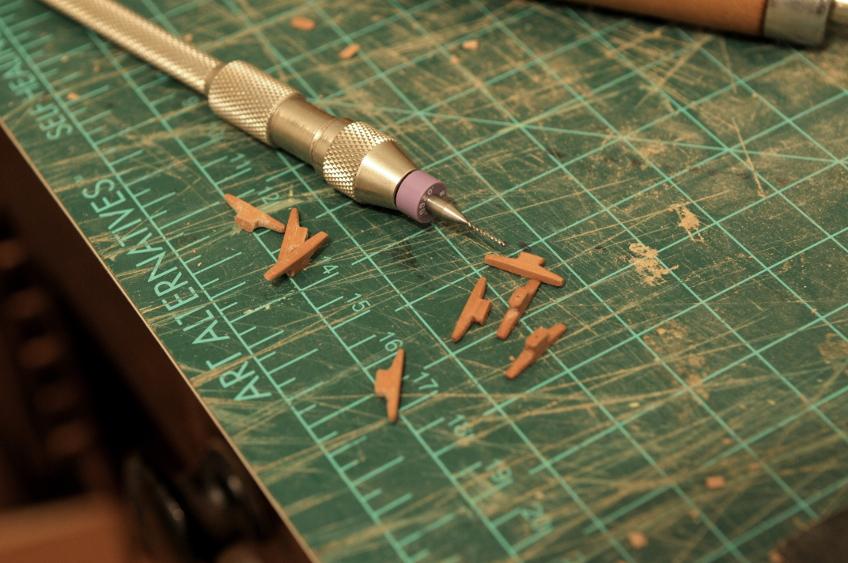
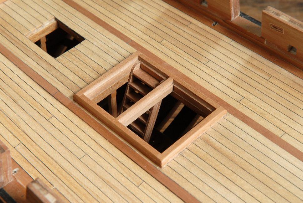
Ladders
A few ladders were made for the crew to travel between decks. The two on the right are "rejected" first tries--
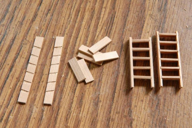
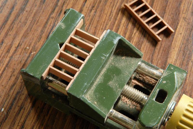
Like the rudder, these will be glued later.
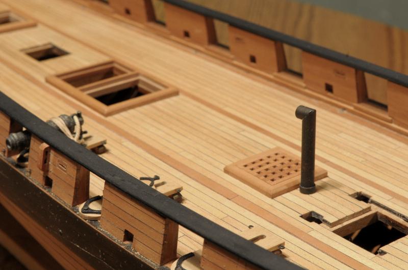
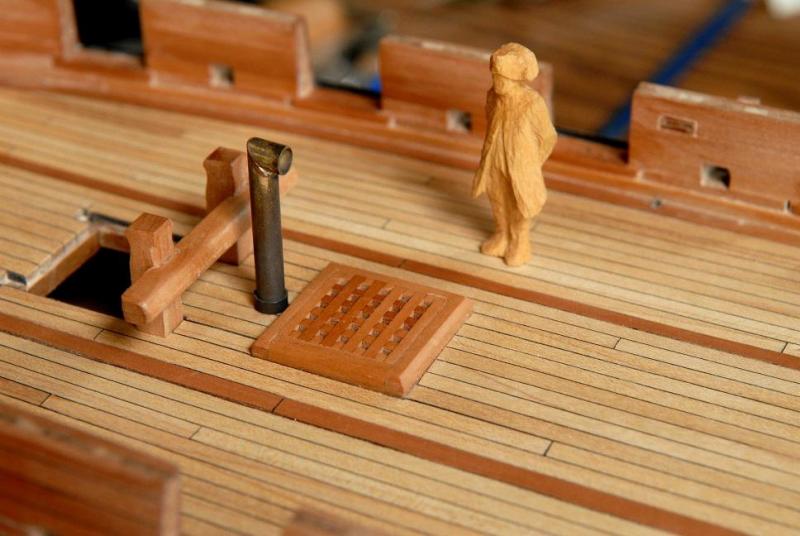
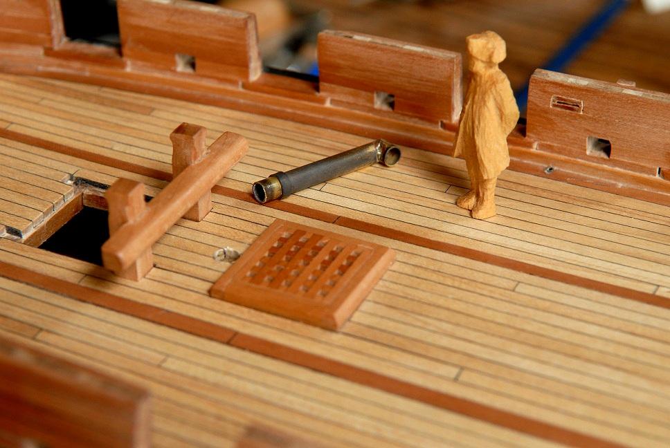
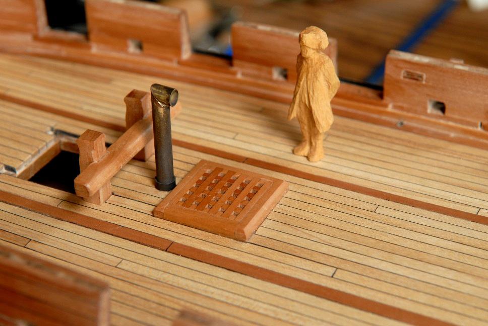
Stove vent
Brass tubing was cut, soldered and blackened, though the first blackening wasn't very successful. You'll see better result on that later--

Ron
- CiscoH, BETAQDAVE and themadchemist
-
3


Civil War Picket Boat by rafine - FINISHED - Model Shipways
in - Kit build logs for subjects built from 1851 - 1900
Posted
Congratulations, Bob! Outstanding job on your picket boat. I enjoyed following along.
Ron