


rlb
-
Posts
651 -
Joined
-
Last visited
Content Type
Profiles
Forums
Gallery
Events
Posts posted by rlb
-
-
Hi Keith,
Can't help you much on the book question. For what it's worth, my copy was published by "Bonanza Books, a division of Crown Publishers, by arrangement with W.W. Norton & Company". I'm not sure what year. It has the same front cover to the dust jacket as the 1949 example you linked to--but the back dust jacket image is different on mine. My copy has 558 pages.
Ron
-
Thanks, Russ!
Tom, that seems like a pretty good idea. I wish it could have occurred to me at the beginning! I could have adjusted my templates to account for the frame thicknesses. As is, the templates are taken straight from the hull plan, which is the outside of the frames.
I think at this point I'd rather cut slots for the frames, as opposed to sanding another 1/16th inch or so layer of wood off of the plug.
Ron
PS, Tom, after your edited post--I may do some things well, but I'm not an expert and don't have a problem with suggestions!
-
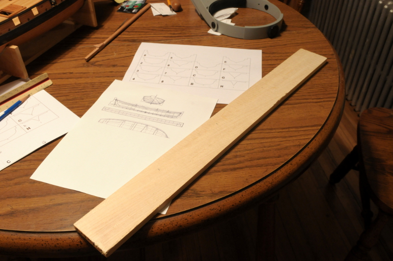
I've been working on the cutter. I should say, the plug for the cutter, which I'll use to help with planking and forming the frames.
I bought a piece of aspen, at a big box hardware store, and, based on an illustration in W.E. May's book, drew some templates which I printed on card stock--

I needed two layers of the aspen to make the necessary thickness. These were clamped and glued--

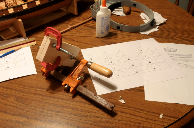
At this point, I found a better cutter plan--a 20'-4" cutter illustrated by Chapelle, (described in the previous post), and I drew up a new set of templates--
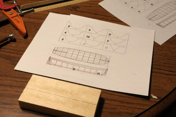
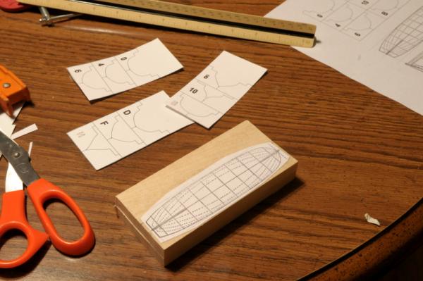
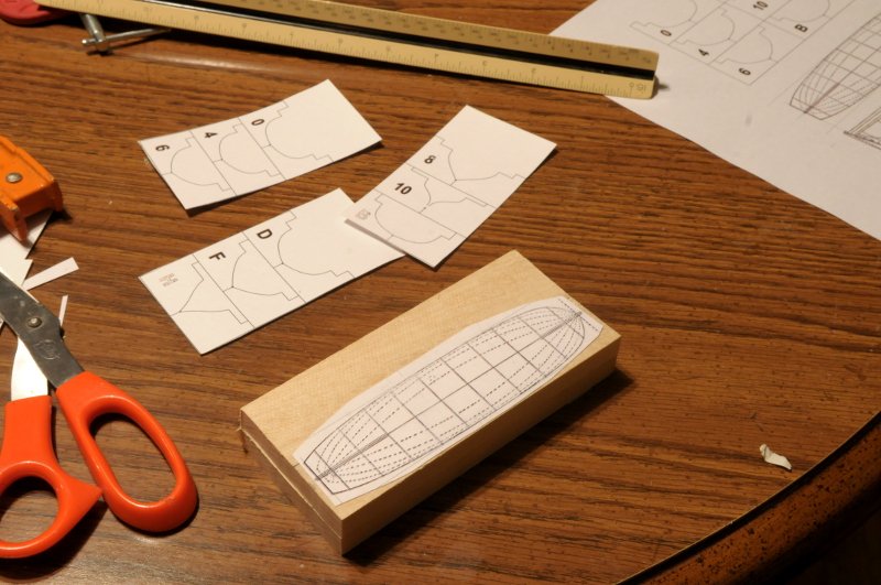
I glued the plan to the aspen block, and I began cutting the templates out--
After cutting and sanding the block to the outline of the plan, I began shaping the plug. This was done by scrubbing on sandpaper, using a knife, and mostly with a rounded sanding block--
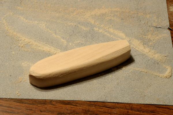
I should have made some photos between the previous one and these. I now worked on one template "station" at a time. I started at the dead flat location, sanding it close to the template, then moving one template at a time forward. When the forward templates were roughly good, I made my way aft. After they were all roughed out, I went back to the beginning and fine tuned the shape, again, one template at a time. After that, I sanded the overall shape, using progressively finer sandpaper. Here's how it ended up--
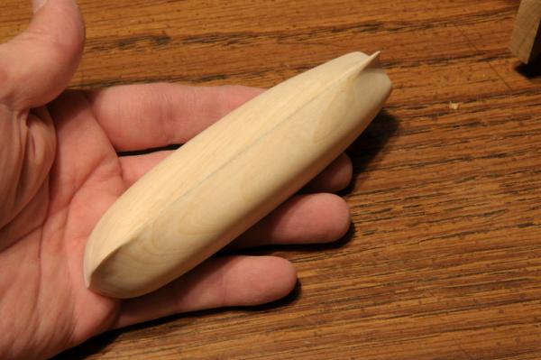
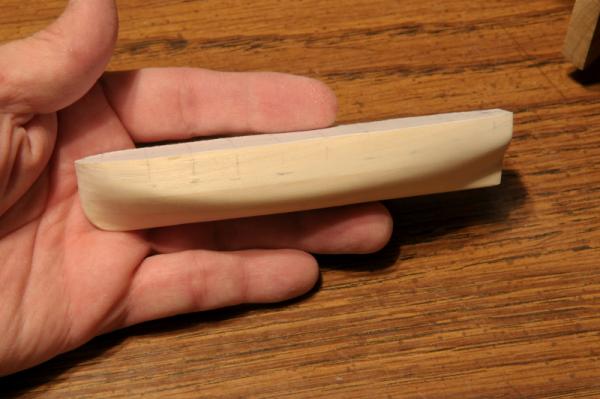
The faint markings on the side give an indication of the approximate location of the sheer. When done, the actual cutter will be substantially shallower than the plug.
The shape looks good to me. Now I need to cut a slot in the plug for the keel, (and probably the frames) and then start building the backbone of the cutter.
Ron
-
I've spent more time on the hawse holes, but I'm also planning ahead for a ship's boat which will be made fast to the deck, and needs to be built soon. An ongoing source of angst for me has been trying to determine the dimensions of this boat.
Chapelle lists a 20 foot cutter as one of Oneida's boats, and to help me in trying to determine the other dimensions of this boat, I have the following references:
The Boats of Men-of-War by W.E. May
The History of the American Sailing Navy by Howard I. Chapelle
The Built-up Ship Model by Charles G. Davis
Ship plans available on the National Maritime Museum website
There seems to be a wide variation in length to width ratio for ship's boats between c1800 and c1850, and/or between English boats and American boats.
In May (who is writing of British practice), c1800 a 21 foot cutter would have a width of 6'7", which is a length to width ratio of about 3.2:1 (In his table, he does not list a 20' cutter, so I chose the closest available size.)
According to Davis (who writes of American practice), the length to width ratio of cutters was 4:1, so a 21 foot cutter (to compare with May) would be 5'-3" in width.
Chapelle lists many boat dimensions in an Appendix, though they are all dated later than Oneida. The closest example is for an 1821 Schooner, with a cutter of 20'4" having a beam of 5'3". This would be a 3.87:1 ratio , close (sort of) to Davis' 4:1.
Additionally, there is a 22' cutter (1808--right on my time frame) on the NMM site, which has a beam of 6 feet. This is a 3.67:1 ratio.
I'm going to follow Chapelle on this--making a 20'4 cutter, with a beam of 5'3". He includes plans for this boat in his book, so I'll scan and enlarge the plan to scale, and cut out templates so that I can make a "plug" to form the frames, and lay the planking upon.
I welcome any additional observation and insight any may have on this!
Ron
-
Congratulations, Adriaan!
Nice job. You've pushed on through more than the usual rough patches and finished with a great model.
Ron
-
Thank you very much B.E., Alistair.
Bill, thanks. All of the recent work, and most of the model, is Swiss Pear. The hull and deck framing is American Cherry, the deck is Maple, and there is some (only on the stern at this point) Castello Boxwood trim.
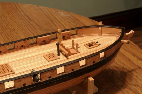
I'm not counting this as an official update, but I did get some work done today, just not much worth showing. I epoxied the bulwark pin rails, and some additional cleats. Did some work on enlarging the bowsprit hole with a file, and started locating the hawse holes--
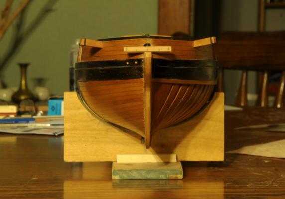
There is a piece of wood marked with the correct (I hope!--using Charles G. Davis as a reference for this) spacing, sitting on the stem. Rather difficult locating the holes along the angled bow, but they look pretty close in the photo. The holes vary from where they are drawn on Chapelle's hull plan drawing--
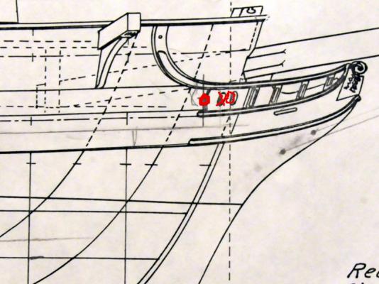
However, in this case I trust my locations more than Chapelle's drawing--I suspect he "eyeballed" them rather than working it out. Not a big deal, but it might end up having some minor effect on the head rails vs. how he drew them.
Ron
- themadchemist, Dubz, Bill Hime and 4 others
-
 7
7
-
Sam,
You're really doing excellent work on this kit, and your efforts to look beyond what the directions say are well worth it!
She's coming along beautifully.
Ron
-
Not boring at all, Russ. And looking good!
Ron
-
Hi Andy,
Checking in periodically on your great lakes build. A departure from your beautiful Pegasus! Looking forward to more.
Ron
Quando Omni Flunkus, Moritati -- Et tunc erant 'life.
-
Hi Gil,
Outstanding work.
Thanks for your log and all the details on how you've done things. It's so helpful.
The lower right photo in post #297 could easily be a photo of the real ship. (I thought is was, at first glance!)
Ron
-
-
Hi Lou,
I'm just seeing your Harvey for the first time, you started it when I was on a long modeling hiatus, and I'm slowly checking out models for which I missed the start.
Great job. Beautiful planking, pleasing, precise work all around.
You really nailed the "painting with wood" idea. I was going to say that the careful use of red paint on the deck furniture was a good choice, until I went back and paid closer attention to the photos and what you wrote. So, now I say that the careful use of redheart wood was a great choice! It's really striking how red it is!
Looks like your start on the rigging is up to the standards of the woodwork--should be a beautiful model when done.
Ron
-
Thank you all, for your appreciation of the model!
Dan, thanks for adding the portraits! I do love the history. All were present at the building:
Christian Bergh designed Oneida, and built her with Henry Eckford. James Fenimore Cooper wrote a little about her building and serving aboard her as a midshipman, but, as you first guessed-
My eye on the ship is Lieutenant Woolsey. And not because he has the best first name (Melancthon) of the four. From Wikipedia: "he was ordered to the shores of Lake Ontario in 1808 to supervise the construction of Oneida."
Since he also commanded her for a time; I figure he had a lot riding on how she came out!
Ron
-
-
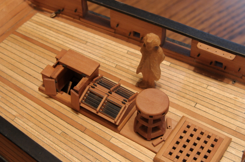
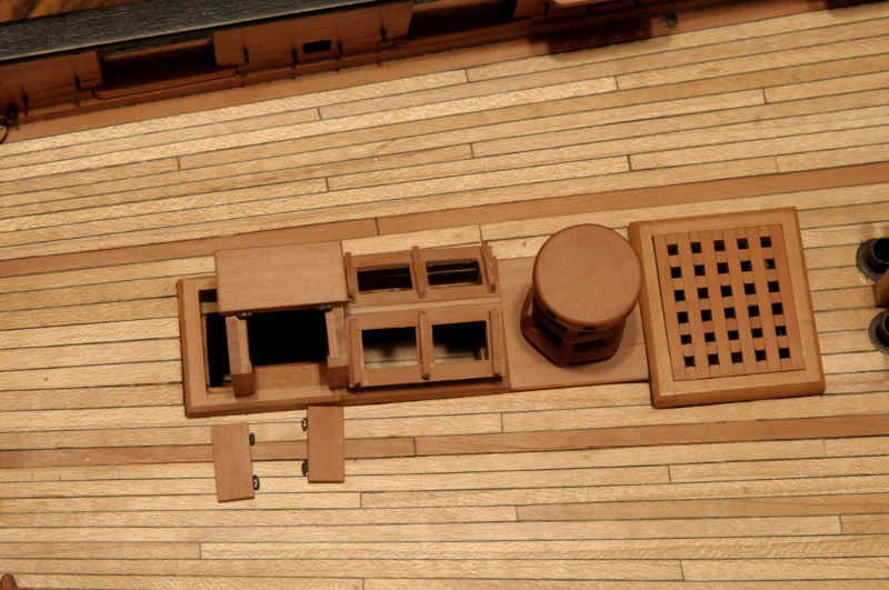
Continuing on with the aft coaming area--
Here the blackened brass rods are fit to the skylight sashes, and dry fit on the frame--
The skylight hinges are trimmed short. You can see where I've cut a small mortice in the skylight for them to sit--

The binnacle is started from a solid block. I've also epoxied "glass" (cut from the plastic address window of an envelope) on the underside of one skylight sash--
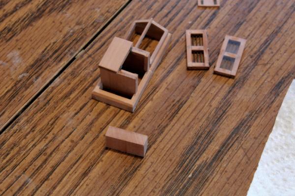
The center is cut out of the binnacle block. I've glued the hinges onto the skylight sashes, and you can see the effect of the glass in the skylight--

A top is made for the binnacle, and holes are drilled in the center. A larger size from the top (the width of the compass) and a smaller one all the way through, to push the compass back out from below during test fittings--
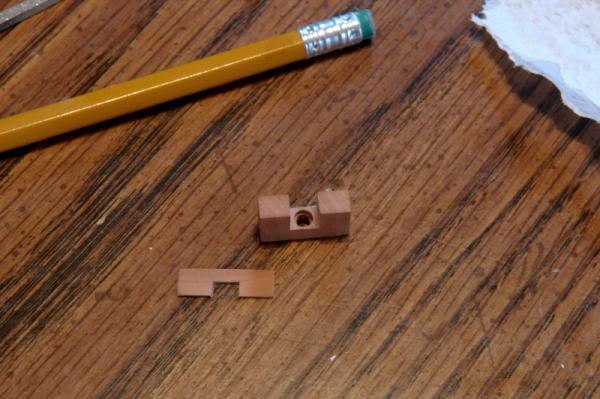
In this photo you can see two sections of brass tube soldered together. Inner tube will form a seat to glue the compass face to. For the compass, I smeared the corner of a piece of white card stock with some stain, so it wouldn't be so bright. Then I epoxied some "glass" to it. After not doing a very good job cutting a tiny circle (that's where that little cut out in the corner came from), I got the idea to file the end of a brass tube to make a punch--
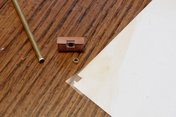
The punch worked great, but I ended up making another from the next smaller tube, as this left a little gap between the brass tube and the compass face--a hint of a gimble assembly--

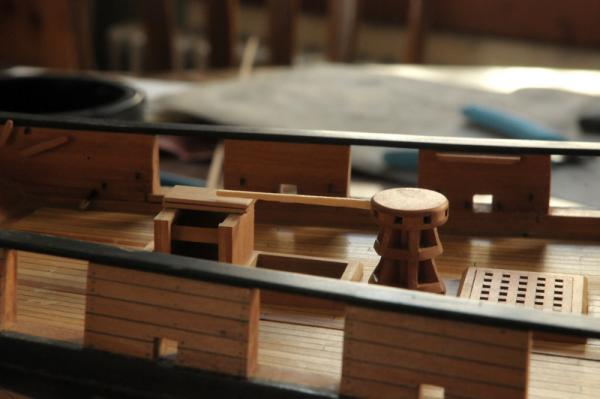
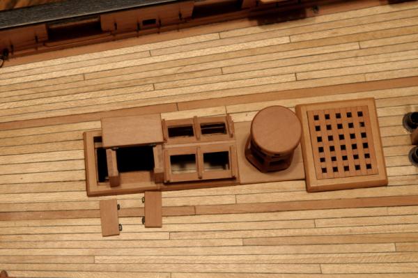
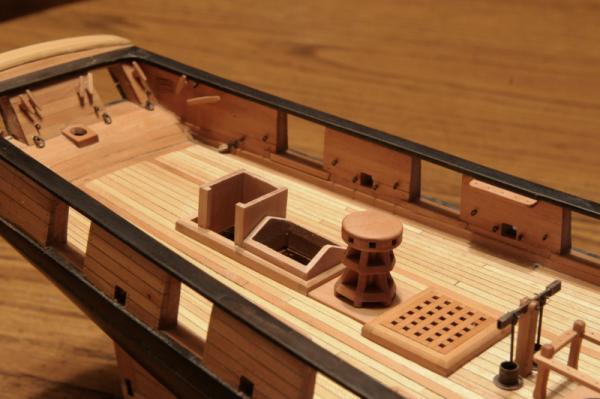
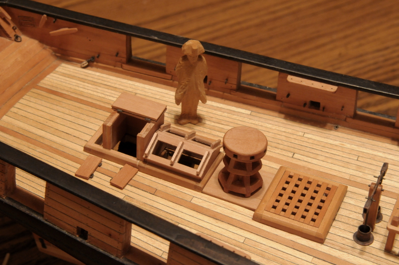
After much frustration and delay with the companionway doors (re-gluing hinges multiple times), everything is finally there. Some is glued, some is just sitting (the binnacle). There's no hardware (i.e. latches, knobs, etc.) on the companionway doors, or the binnacle doors. I'm still deciding whether to add anything to those. I have a hard time controlling epoxy smears, and my CA has all gone bad, so for now they'll stay as is--
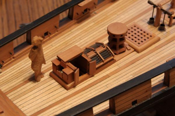
The binnacle is pretty short. It's that way to stay below the companionway top, which overhangs its sides about and inch and a half.
I think the visibility through the "glass" is just about perfect--

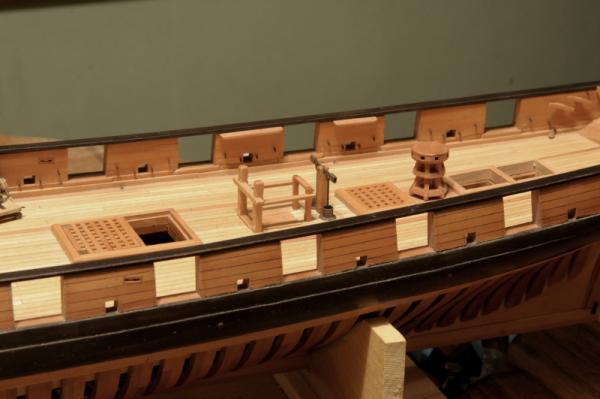
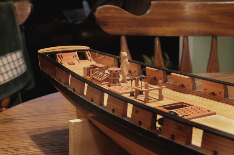
A longer "context" shot. The deck is looking a lot more finished!
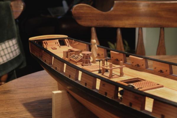
Ron
- tlevine, Elmer Cornish, hamilton and 12 others
-
15
-
Congratulations, Remco! Super job.
Ron
-
Continuing with the aft features:
I can't believe it's taken me all day for this progress, but here's what I've done. (I often suffer from a need make progress, but I must say--I did feel a sense of relaxation doing a lot this work--simply because it took so long, and I had to forget about actually finishing anything!)_
After making the top pieces of the companionway, check to make sure the capstan bars (in this photo a trimmed toothpick) will clear the companionway in it's open configuration--
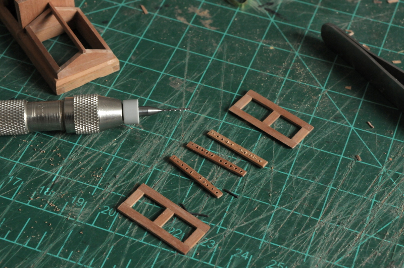
Cut the pieces for the skylight "sashes". A large part of why this takes me so long, is that I don't have milled wood the right size. All of these pieces are sanded down by hand from larger stock--
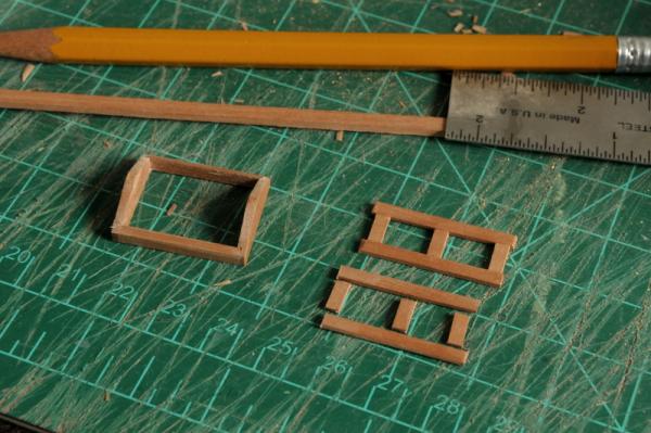
Drill holes for the brass or iron (haven't decided yet) bars in these pieces. Easier to do them in double sections before cutting them to their individual pieces--

Cutting the doubled pieces apart and filing the ends--
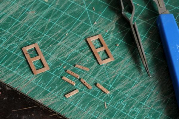
These are then glued on to the skylight sashes--
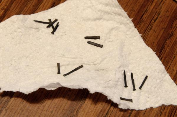
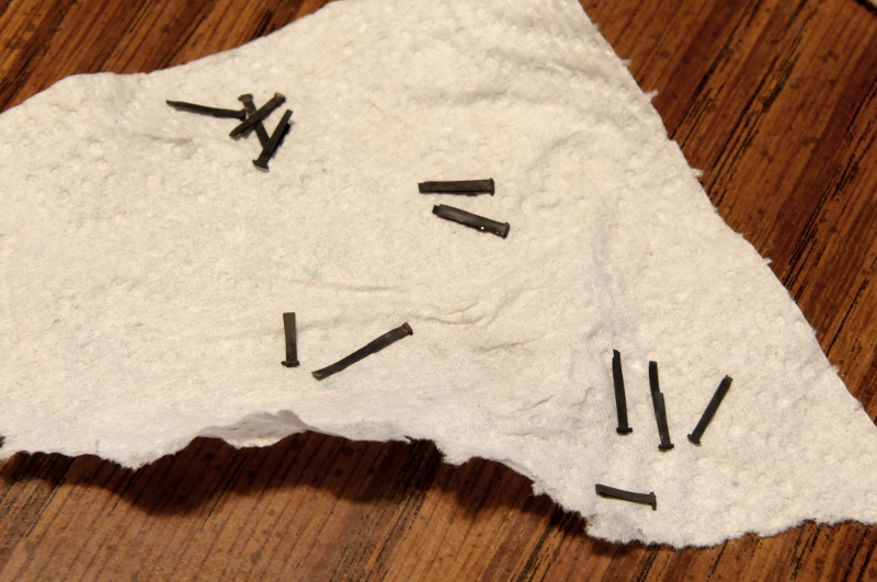
A number of hinges are made, out of brass sheet and wire, and then blackened, for the companionway, and the skylight--
Here's where I'm at. The upper part of the companionway is done. The doors have hinges glued to them. The skylight sashes need some "glass" and their hinges, and then I'll glue the sashes onto the frame, and put the rods in--

Ron
-
Thanks, Elia,
Yes, I too spent some time thinking about what should go aft.
No way to know if what I've done is accurate for Oneida, but I can make an argument for it based on what I've seen of other brig models. If nothing else, the variety of what I've decided to show gives me some good modeling experience.
Ron
-
Beautiful and precise work, Elia.
Lots of little pieces to make, and they all look great.
Ron
-
-
Finishing up the pin rails:
Here's how I revised them, so they continue around the aft post at the same height.
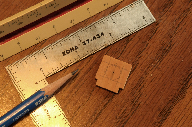
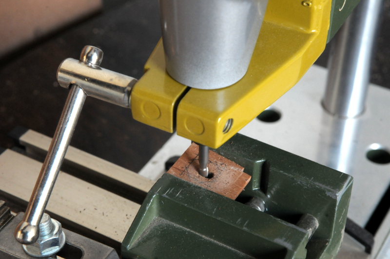
Moving on to the mast partners, I drew an octagon with at the correct size of my masts--

And milled the center out, a little smaller than the drawn octagon. Notice the wood is at an angle to account for the mast rake--

I filed the corners of the octagon a little better, then fit the partners on the deck. The octagons will need to be enlarged to fit the actual masts when they are made--
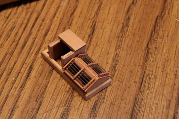
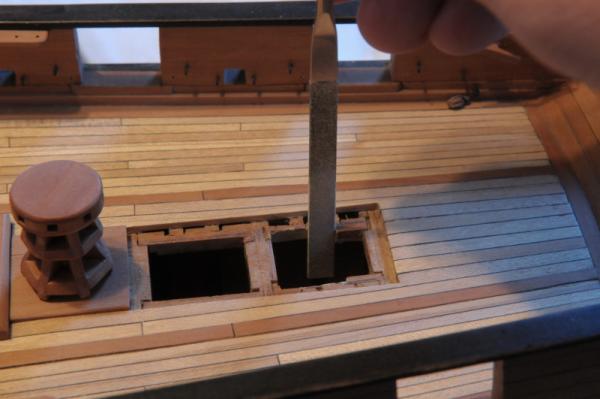
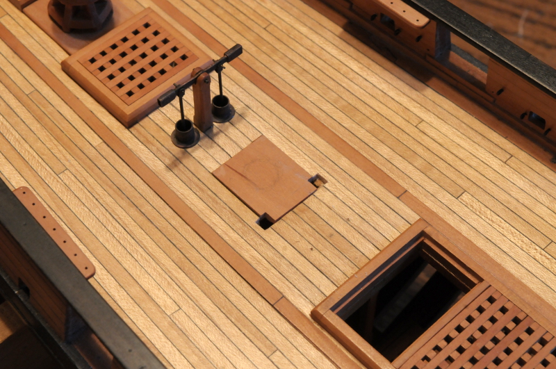
The aft hatch arrangement:
I finally settled on what to do with these last hatches. It's changed from my initial idea, and I needed to do some surgery to the framing to accommodate a companionway in the second opening--
I glued in a ladder I had made a long time ago--
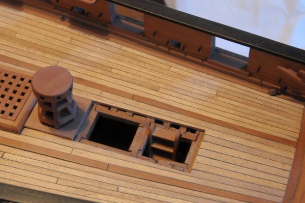
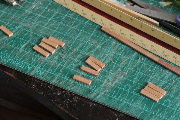
Some pieces cut for the companionway sides--
The pieces that make up the sides were glued together, and when set they were sanded flush, trimmed to the right size, and glued into a "box"--
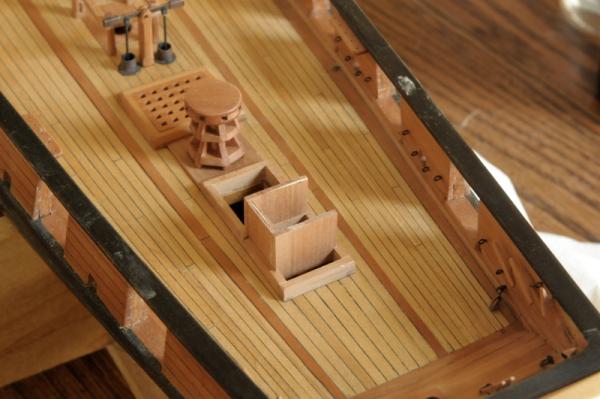
Just aft of the companionway, on what's left of the coaming, I'll build a binnacle.
The opening forward of the companionway will be a skylight. Here is the frame test fit--
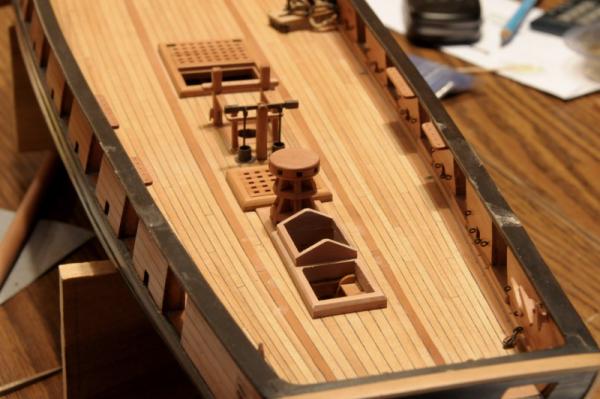
And then both test fit together--
Ron
-
Hi Russ,
I know doweling those pin rails is a good idea, but it's very small and three pieces coming together at one place. I'm afraid to drill into the wood in two directions at that aft corner where the two pin rails come together. I put some generous fillets of glue underneath, where it won't be visible. Perhaps before I glue rail sub-assembly onto the topsheet bits (this joint does have epoxied pins) I will drill and put some treenail dowels into those corners.
Ron
-
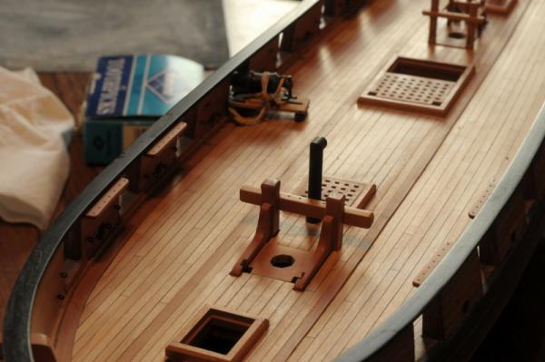
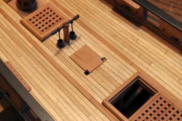
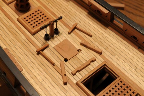
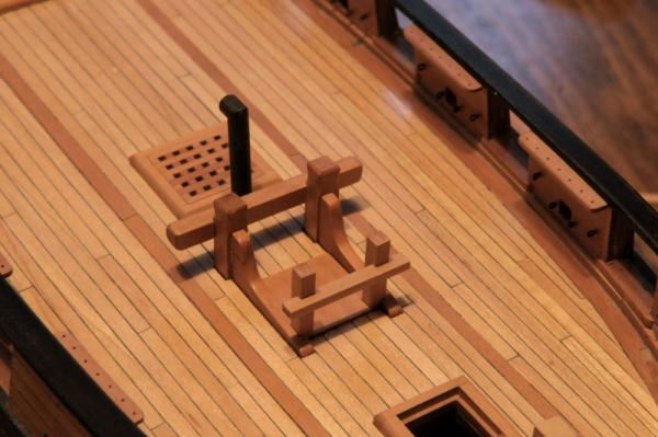
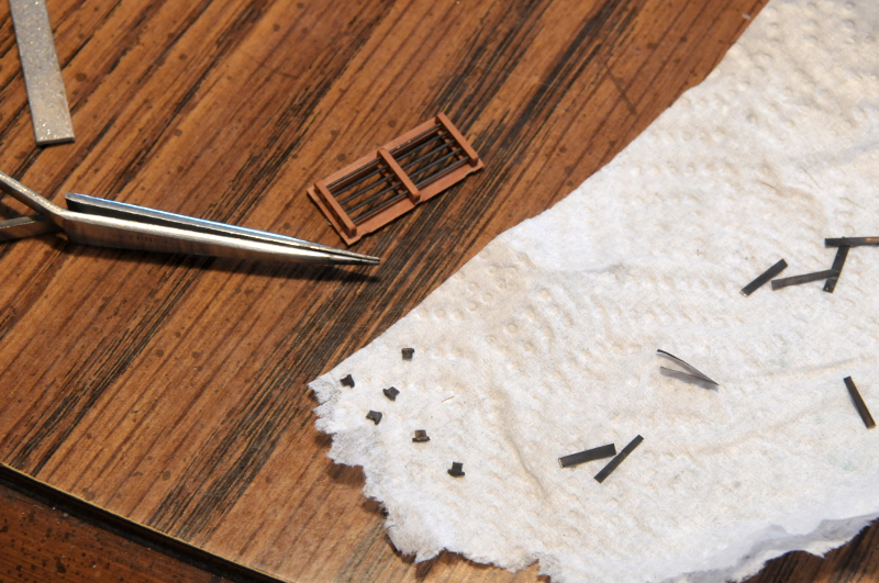
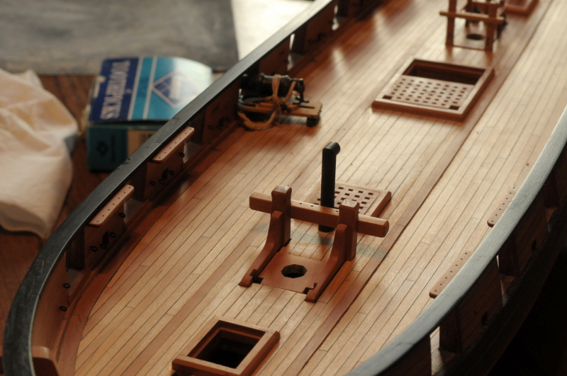
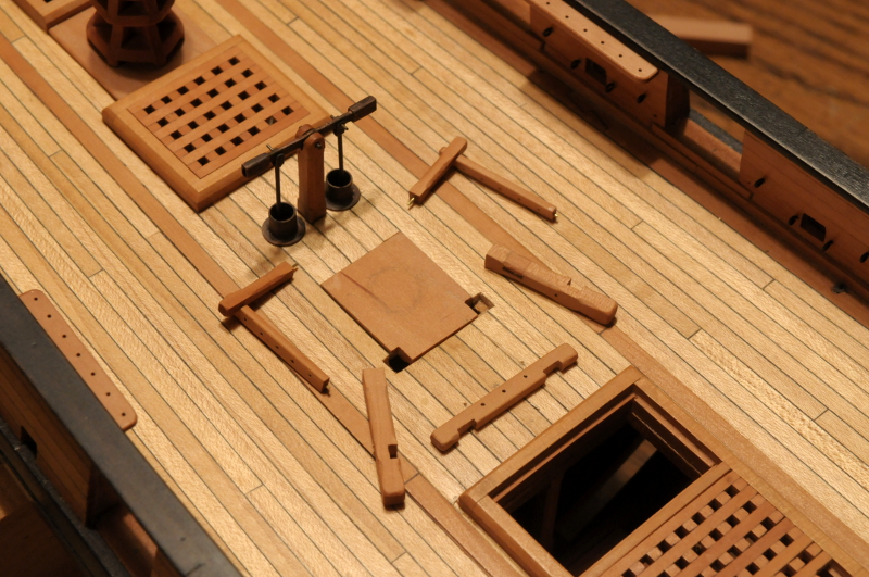
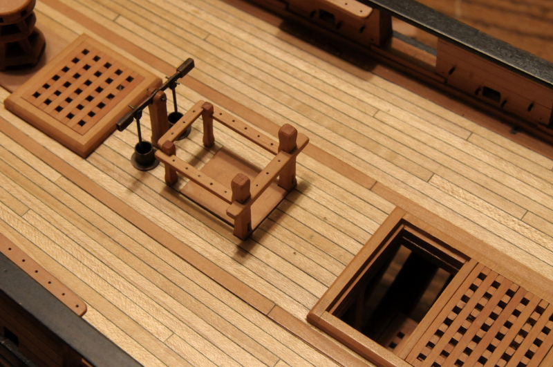
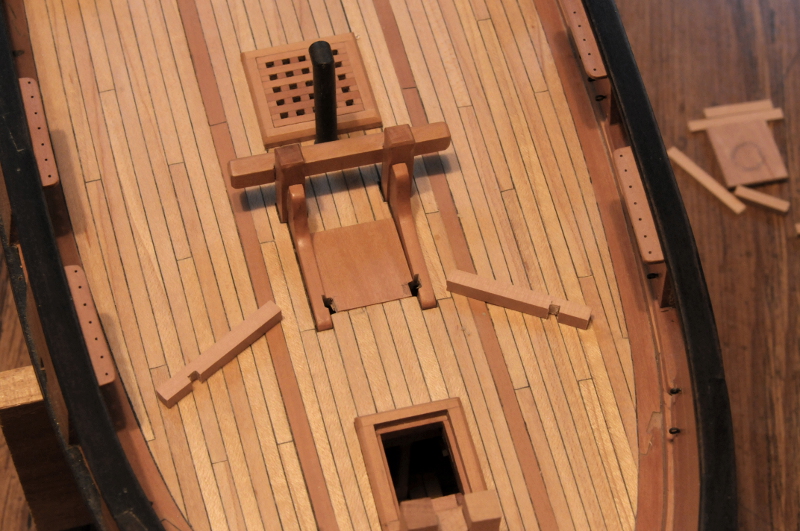
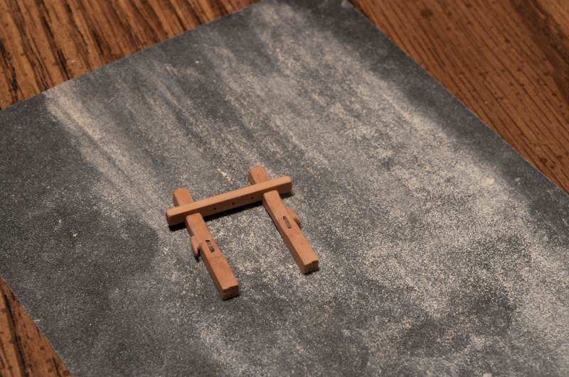
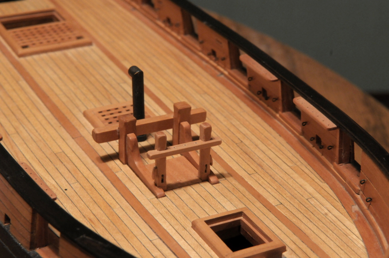
Continuing on with the topmast sheet bitts--
The main pieces are similar to the fore mast sheet bitts, but for the main mast there are some extra pin rails and posts.
First, the partners, and the decking are notched for the bitt posts--
These are dry fit--

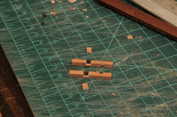
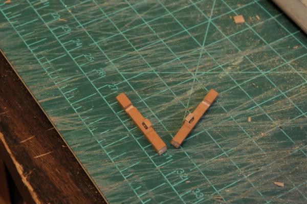
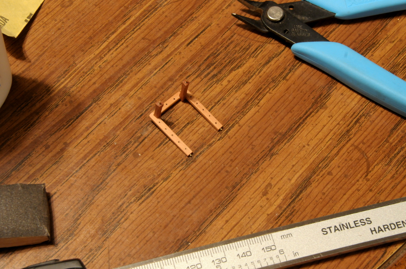
The main posts, aft posts, and pin rails are shaped and partially glued. Pins are epoxied into the ends of the side rail sub-assemblies for strength, and to make gluing easier--
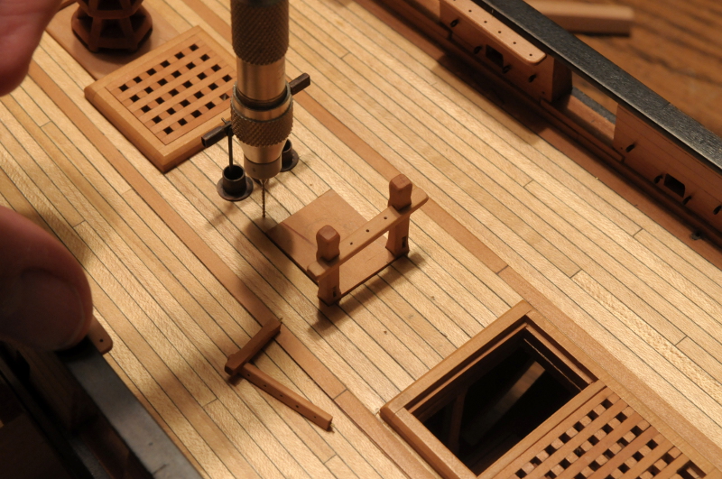
Holes are marked and drilled in the deck for the aft posts--
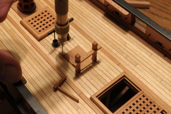
More dry fitting--
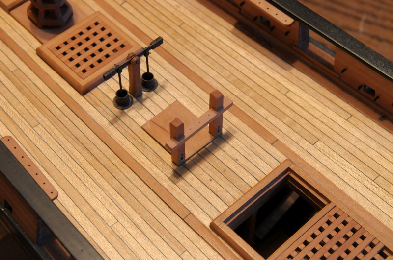
Measuring for fitting the aft pin rail--
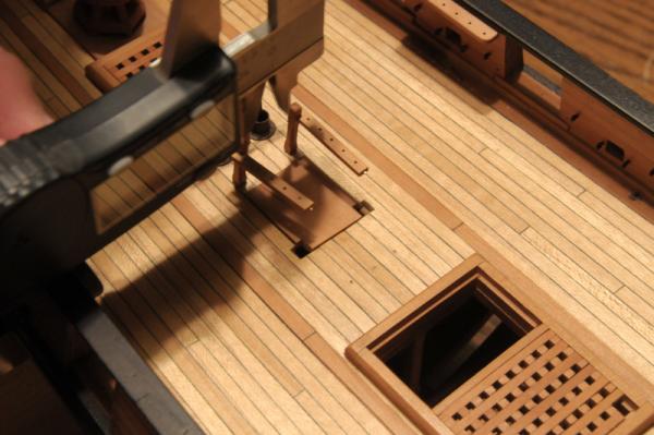
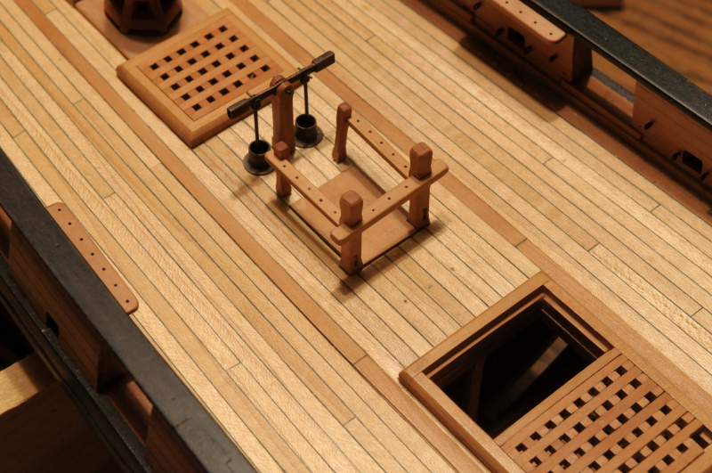
The aft rail is cut and glued to the side rail sub-assemblies--
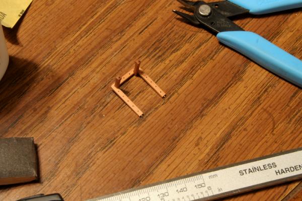
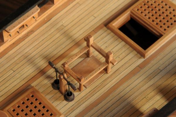
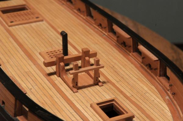
More dry fitting--

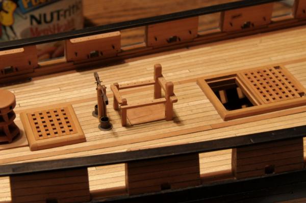
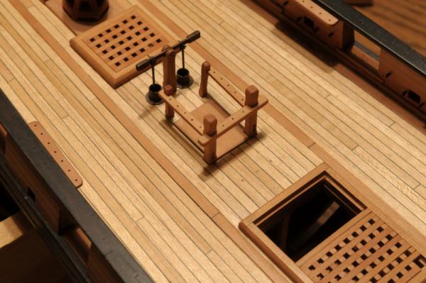
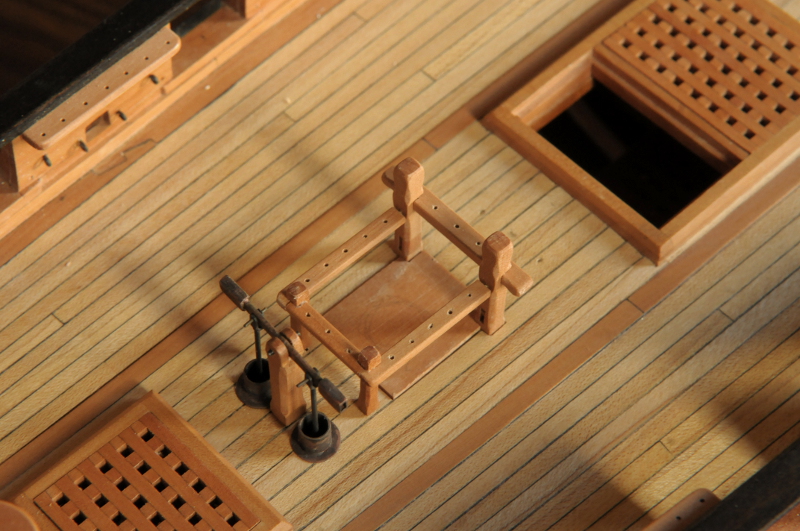
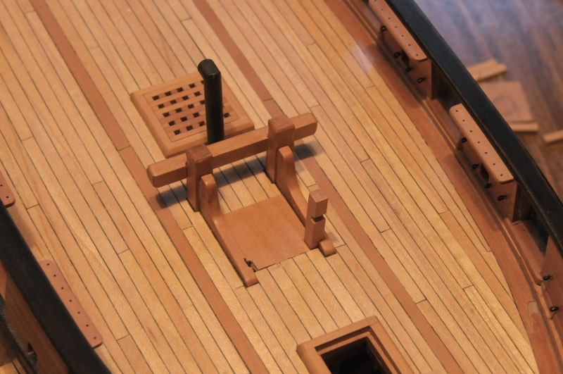
I'm not happy with the aft pin rail. It looks a little flimsy. I remove it adjust the notches, and re-glue it--
This is better, but I'm not sure it's good yet. I was going for something similar in basic concept to the mast rails on the Brig Niagara replica, where the side and aft rails are at different heights, but I'm not sure I like this. I think I will remove the aft rail, trim it, and the side rails, and attach it so that all three are at the same height.
The sheet bitt posts also need the side cleats made and attached (as on the fore mast sheet bitts), but those and the rail adjustments will have to wait for tomorrow.
Ron
- Blue Ensign, Martin W, Adrieke and 8 others
-
11
-
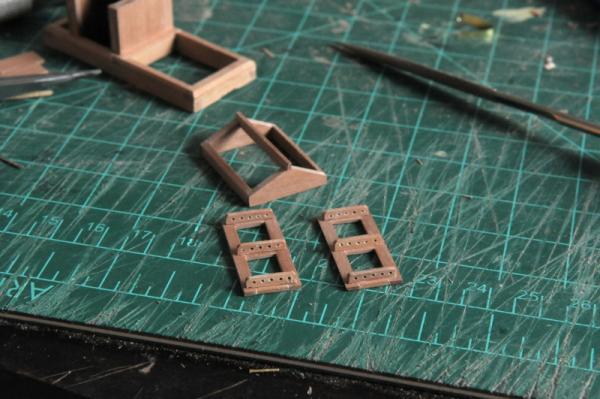
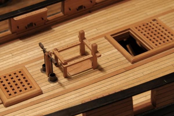
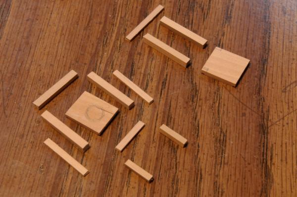
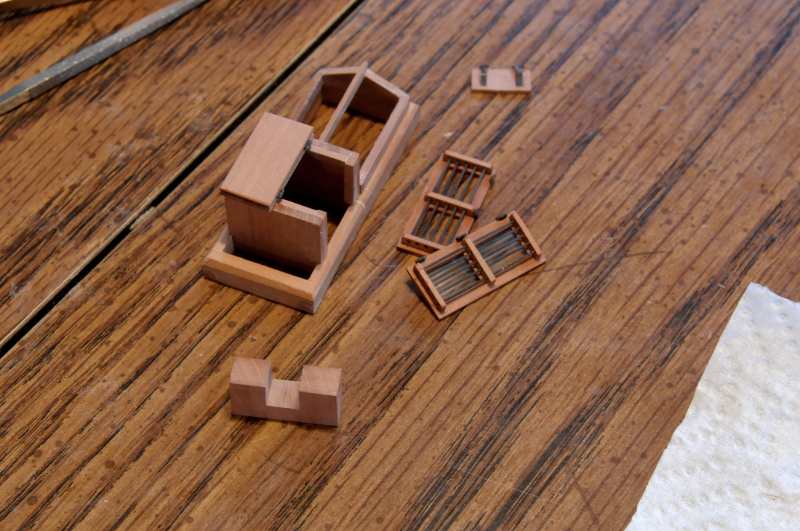
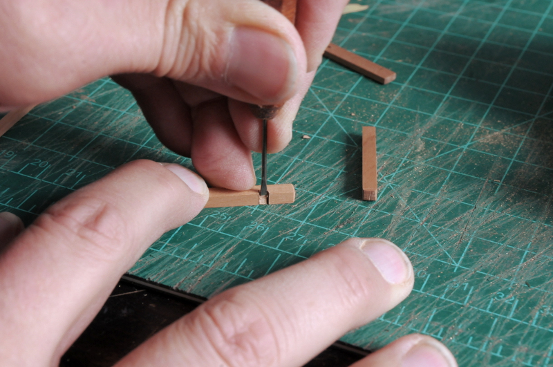
Today's project was the topmast sheet bitts.
Here are the basic pieces for both the fore mast (above) and the main mast (below). Some square posts, pin rails, and the as yet unfinished mast partners
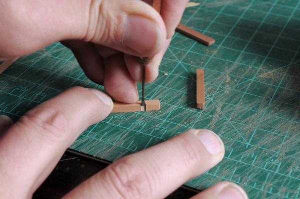
I began working on the fore mast bitts. These are the simpler of the two, with only one pin rail, athwart the posts. First I cut the notch for the pin rail--
And chiseled it out--
Here are the two posts laid on the deck. The knees for the riding bitts need to be notched to receive the posts, and the mast partner piece will also be notched out in the corners--
One post is dry fit--

Here are the two posts and the pin rail dry fit--still a lot of work to do--
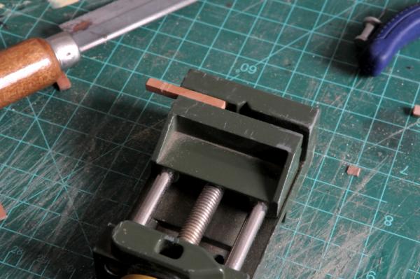
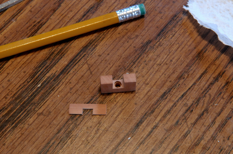
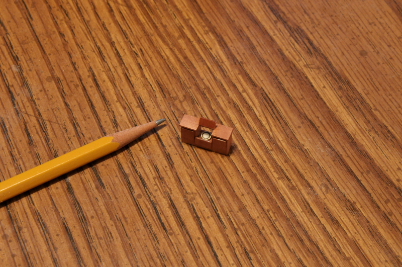
A sheave needs to be put into each post. Here are the posts notched for the sheaves, which are stained pieces cut from a dowel--
After the sheaves are glued in, a filler piece is glued, these will be sanded down flush--
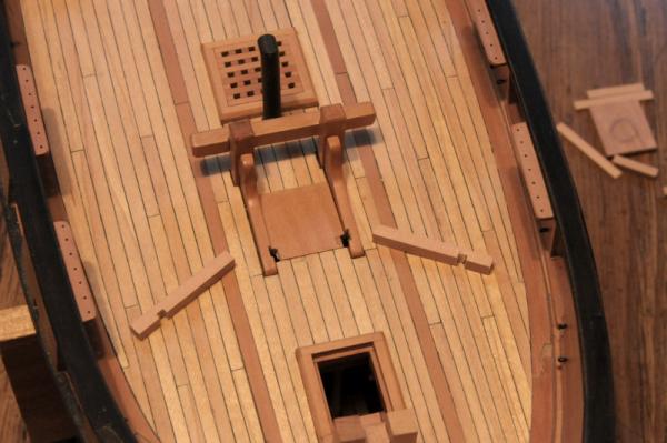
After sanding down the filler pieces, adding a cleat to each side, and some further chamfering and shaping, here are the fore topmast sheet bitts--

And dry fit on the model--
Ron
- garyshipwright, Elia, mtaylor and 10 others
-
13


US Brig Oneida 1809 by rlb - The Lumberyard - 1:48 scale - POF - Lake Ontario Warship
in - Kit build logs for subjects built from 1801 - 1850
Posted · Edited by rlb
Keith,
Good thoughts on the plug. I do plan on planking over the plug first, without frames. Then taking the shell off, and inserting the frames afterwards. The purpose of notching the plug for the frames would be so that I can use the plug for bending and "setting" the frames, before transferring them to the planked shell.
I have a tutorial by David Antscherl that shows this method. But I've been keeping my eyes open (and noting suggestions!) and have seen some other ways of doing it.
The cutter will be clinker planked.
Ron