
Bedford
-
Posts
1,299 -
Joined
-
Last visited
Content Type
Profiles
Forums
Gallery
Events
Everything posted by Bedford
-
 Well Floyd I always wanted to rely on sail but with no-one else around here sailing I thought it was a pretty good idea to include auxiliary power. I am still looking at it but since I will have to buy a new speed controller I might just as well get two smaller motors too. Much less weight and the 540's are big enough to drive a much larger vessel.
 -
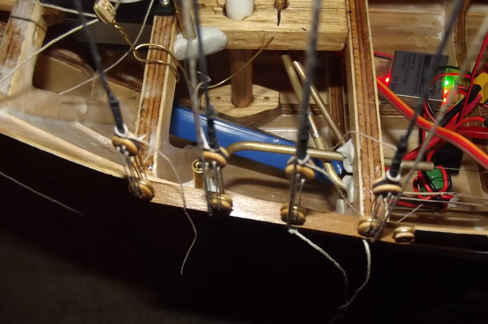
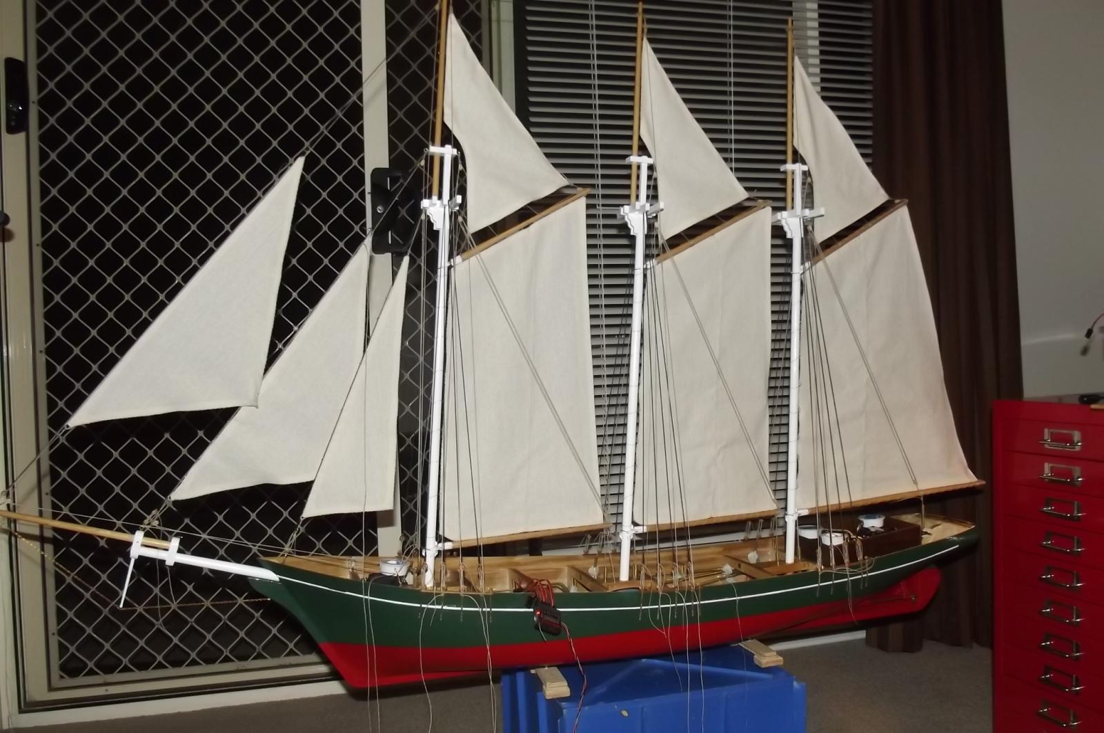
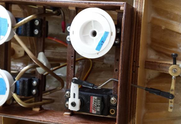
Today has been the first real time I have had on the schooner for a while and while I am achieving a little I am taking about 5 steps back for each step forward. Firstly I have commented in the past that when I power up the radio system some of the winch servos travel in and out which causes great concern because it is all at once and I have no control. While the extra BEC I bought to supply power to the system has cured the glitching that was occurring with all the servos connected it has not stopped the servo "reaching" that occurs on start-up so I went and bought a few more servo extension leads of different lengths so now I have the joins in accessible places meaning I can stow her with these servos disconnected and when I power up the system I can connect them one by one with no misbehaving. Problem solved. However! In trying all this and making sure it all worked the main gaff lazy jack gave up and broke, I can't see why, there was no big harsh snap like before, it just seems to have failed so I will have to replace it and am still considering whether or not I will increase the size of the line which means replacing all three of them but may be worth it I think. And then! I tried the motors just to make sure all is well...................................dead as the proverbial Dodo! I checked the switch and it isn't the problem so the speed controller itself must have died for no apparent reason. Anyone want to buy an unfinished schooner? Seriously though, it is more of a challenge than I was hoping for but one day I will win. Oh and I floated her just to see how the weight is going and she is heavy in the stern as I expected because of all the servos down there as well as the motors and she is listing a few degrees to starboard which I figure is mainly due to the location of the servos in the aft deckhouse with the rudder servo being in the centre so I have relocated it as far to port as I could. You can see the holes where it was mounted right beside the winch servo. Now to really plan where everything else gets mounted because I want to level her out with essential hardware rather than with added ballast because that would mean less weight for the sailing keel. I have read that you want such a vessel to ride a bit high in the bow, makes them sail better, so it is heading in the right direction. I MAY however decide to ditch the motors as they are quite heavy and if I learn to sail the yacht I may not need them in the schooner.
-
Beautifully done my friend and nicely displayed.
-
This is going to get quite intricate, at this size the cam and valve gear will be very small. I don't want to miss any of it!
-
Clearly you have some years of experience in machining Michael, so interesting to follow.
-
She's beautiful! Think I will have to watch this take shape.
-
How do you get the brass so smooth after machining?
-
Impressed Michael, very impressed!
-
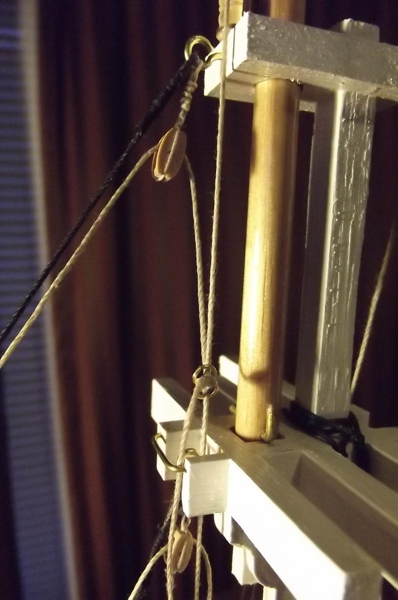
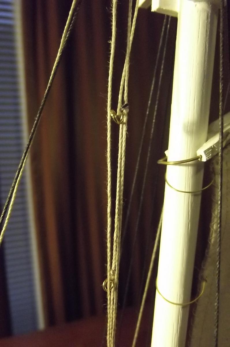
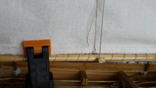
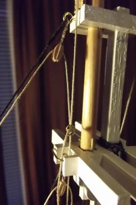
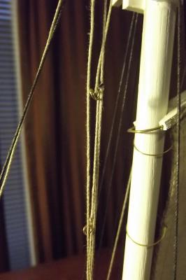
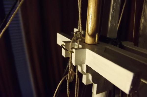
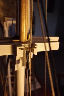
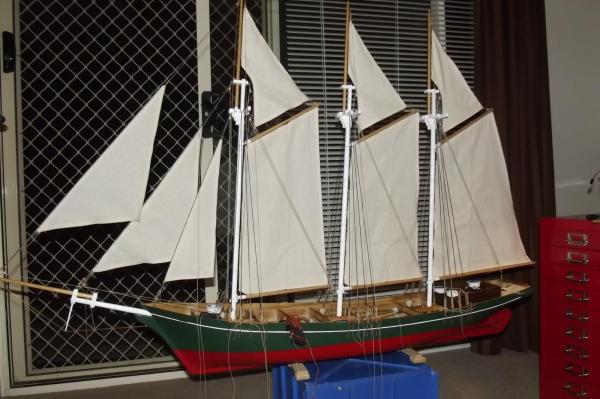
Here is the last sail raising video you will see until she is in the water, It is a great relief to finally have all of them done, all that remains now are the sheets for the stays'ls which will pose their own challenges. I have tried to show how the rings work to raise and lower the stays'ls through differing ranges of travel but I can't do slow motion. Basically I have made the outer stays'l the master since it travels the furthest, I tied a ring into that line and another into the other two lines at the appropriate places and ran each line through the ring of the next so that when it reaches the next ring it pulls it down and raises that sail etc. I did the same in reverse to lower the sails. When the sails are all the way down the top ring goes above the cross tree so I had to thin and fair the timber on one side to allow it to slip through without catching and you will see at the 14 second point that there is a loop that forms above the cross tree, this was prone to catching on the cross tree when being hauled down so I added a brass wire guide to keep it from doing so. You will see that in the pics below. This pic shows the slack line that was catching on the cross tree, the wire guide did the trick! This shows the faired cross tree timber.
-
Making the spark plugs and all, you're a better man than I Gungadin !
-
Looks like there will be a wealth of knowledge there. Will you make your own spark plugs? I have a contact of a bloke who sells them, not sure if they are small enough though. Steve
-
Thanks guys, Bob there is still a long way to go yet. I will drop a little bomb here and say I doubt she will sail before I sail from Sydney to Hobart aboard the replica Endeavour in late Jan/early Feb next year. A 10 day voyage aboard that magnificent bark culminating in the wooden boat festival in Hobart which is a big deal for wooden boats, both 1:1 and scale so I am really looking forward to that !! They also have r/c sailing there so I will be keen to pick up a few tips...
-
Am I to assume from the pics of the real engine that it has a total loss lubrication system, ie the oil pot on top of the engine? If so I imagine that would simplify things too because it won't have an oil pump.
-
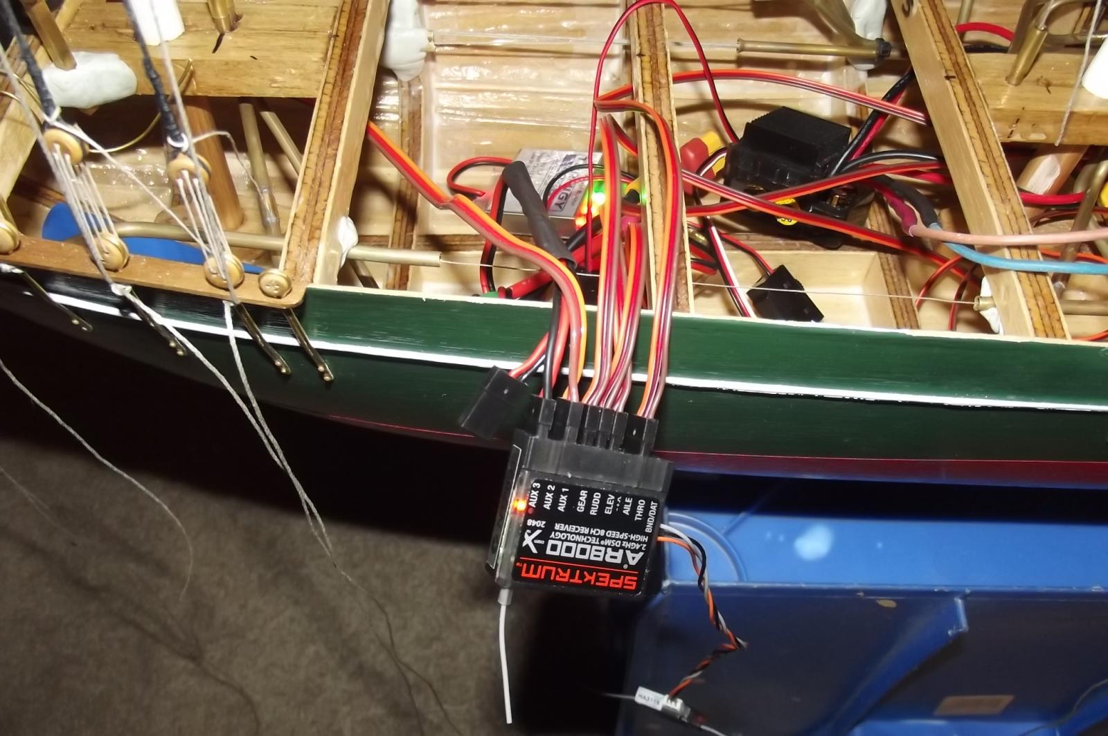
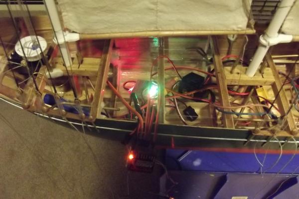
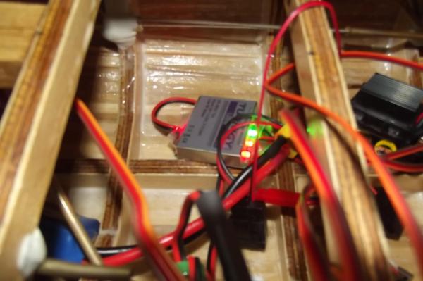
After a lot of googling and researching I have bought a UBEC that can deliver 6 volts and 8 amps with a peak of 15 amps. The device is designed for LiPo batteries which are quite a bit lighter than the NiMH battery I had and the connectors are new and different so I decided to bite the bullet and go LiPo. I bought a bunch of the new connectors too and re-fitted the whole system, they are gold plated and should make better contact than the old ones but the wires have to be soldered on which in my case is no problem as I am an old hand with a soldering iron. She is starting to get a bit busy below decks now. This is the UBEC The new battery jammed in to the port bow area I know we have all seen her with sails raised before but this is the first time they have ALL been raised by the radio and it is running very smoothly with no dramas thanks to the new UBEC and when I plug the ESC (speed controller) back in its supply will add to the available power so I am feeling pretty confident that my electronic problems are behind me.


-
I'm with Jim Lad, Huon pine! you're a lucky man, I would love to get my hands on a good piece of that. Perfect for a boat too.
-
This is amazing to see, the way it all comes together. There has been so much planning behind this hasn't there?
-
Good question as weight is not scaled like length, as you say it is much less than 1/8 For anyone who doesn't understand consider a cube which contains 8 litres of water, to make it 1/8th scale you don't just remove 7 litres because this will only make it 1/8th in depth. You also need to remove width and length until they are 1/8th of the original measurement. so 8 litres of water weighs 8kg but at 1/8th scale it would weigh 0.0156kg. Hence my 1/8th scale rc Land Rover which weighs 3.5kg is about correct to scale even though the original weighs 1800kg not 28kg. The really tricky question is will the required weight of the flywheel scale down proportionally to the work it has to do? Or should I just sit back and enjoy what is sure to be a stunning build?
-
I hear you qwerty, the lake is about 130 metres wide and 3 or 400 long, most of each side is easily accessible but the dam wall end could be disastrous and the inflow end is all reeds etc so I would need a canoe to retrieve it from there. They do have some for hire at the lake. If she went down she would be lost forever. Check it out on google maps, Lake Canobolas near Orange NSW. I wish I had the kind of sailing lake Floyd has, 1 metre deep!
-
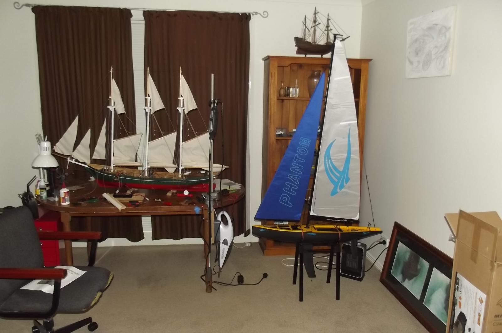
Well that was interesting, I just had my initiation to the joys of sailing. I took the Phantom out to the local lake because it is a fairly calm day. I found a spot where I had the breeze blowing towards me for the most part so if all else failed I reasoned that she would eventually be blown ashore. It didn't take long to learn how to tack her across the wind and I can lay claim to having her sail where I wanted her to, most of the time! There were occasions when the wind in the sails overpowered the efforts of the rudder so I will need to learn more about that. Also there was a while when she was into a head wind and only wanted to go forward, I couldn't get her to come about for a while but eventually she did. If it were the schooner I would have taken in sail and powered her around. Really glad I put auxiliary power in her! I also learned that the rudder I have for the schooner may be woefully inadequate so I will be looking into making a deeper detachable blade for that. I have been googling rc sailing in my area and there is no-one. I think I would really benefit from having someone experienced show me the ropes as it where. Either way, I need to learn a lot more about sailing on the Phantom before I wet the schooner.
-
Well for some reason I am apparently in a country that is FORBIDDEN from seeing the Port Carling sites ? That is the message I get. The launch is absolutely beautiful and I know you will do it justice, I am blown away by the fact that you intend to make a working model engine for it too. I am glued to the chair for this one. Steve
-
Michael, never mind "like" I love that last pic, what an elegant and beautiful bow! I can see why you chose this one and she will be beautiful. Steve
-
Floyd, $148 AUD delivered, and if it isn't a great performer who cares, I see it as virtually a disposable training vessel. There is a mob in Victoria that do a lot with these Chinese mid price sailers as they call them and there are all kinds of tips and mods I could do but probably won't unless I find it a lot of fun. I will however take a hint from what you said and silicone the keel in etc. As for scratch building such a vessel, can't see it in the foreseeable future, I am a classic sail guy. "Give me a tall ship and a star to steer her by" Having said that, never say never.
-
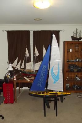
We've all heard of sail training ships, well here's mine. It's a bit back the front in so much as it isn't a tall ship but it was cheap, didn't require much setting up and I would imagine it will be a lot easier to learn to sail on than the schooner. Oh, and if it gets lost at sea, not so distressing ! It will also teach me about ballast and keel depth etc.

-
Twister, thanks heaps! The RMG sailwinch site explains it perfectly and as I hypothesised. I wish I had known about these guys ages ago and they are an Aussie outfit too!
-
Mark, I am looking into various options but there is no point powering up the radio after the ESC as it isn't the drain, it is the limiting factor for the power to the radio and every digital servo adds to the power drain so it doesn't matter if I power them up one by one they will still over tax the system. The extra battery pack idea is apparently what the fly boys do with their big 1/4 scale planes with high power servos, they hook up a battery pack for every servo and since it all connects in parallel they provide built in redundancy because each battery pack powers the entire system. I don't want to go down that path for a few reasons :- First, every time I touch her she puts on weight and I doubt I will be able to put more than 1.5Kg of ballast in the sailing keel. Second, I have already invested quite a few $ in this and doing the extra batt pack idea will add quite a few to the tally. The battery pack I have fitted will be capable of supplying more than enough power to run everything but I need to find a separate way to supply a regulated 6V to the rx. I have considered ditching the current ESC which has two motor outputs and replacing it with two that have single motor outputs. This should double the power available to the rx but has the down side that the ESC's can't be guaranteed to be 100% balanced which could result in the schooner doing an imitation of the Bismark when she was beaten. There is a device called a UBEC which apparently does the job of the BEC (radio power supply) in the ESC and if I get one or two of these I can use them as well as the ESC power supply to feed the rx and they are much cheaper than batt packs. Does that make sense?