HOLIDAY DONATION DRIVE - SUPPORT MSW - DO YOUR PART TO KEEP THIS GREAT FORUM GOING! (89 donations so far out of 49,000 members - C'mon guys!)
×

Bedford
-
Posts
1,297 -
Joined
-
Last visited
Content Type
Profiles
Forums
Gallery
Events
Everything posted by Bedford
-
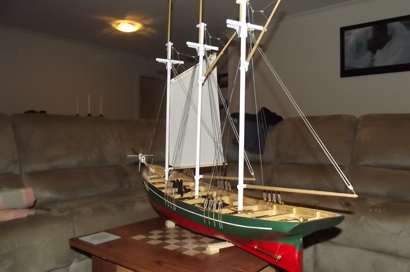
 6 down 3 to go ! With a static model you have to leave all your ropes long enough to tie off but with working running rigging I have cord everywhere, they all have to be long enough to run the travel of the sail plus the height of the mast plus enough to run the length of the ship. Good thing I know what each of them are for.
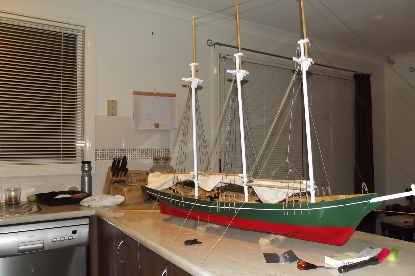
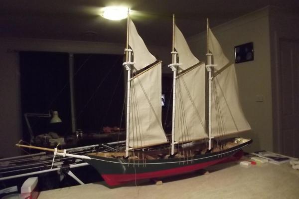

-
Excuses, excuses! You sound like Jake Blues when trying to stop Carrie Fisher from shooting him! I think you have put the HOBBY where it belongs, in your spare time when you feel like it. This will probably lead to better outcomes and less injuries. Enjoy yourself. Steve
-
4 down, 5 to go.

-
James Craig by blueyAU - FINISHED
Bedford replied to blueyAU's topic in - Build logs for subjects built 1851 - 1900
You've got my interest, I love the Craig -
Thanks qwerty, I have had that in the back of my mind but I think you just brought it to the fore. I can see myself making bigger hoops. The sails are going up and down but not always 100% evenly so improvement is needed but I am happy with the progress.


-
Never mind the camera debate, just make sure you take the pics and post them !
-
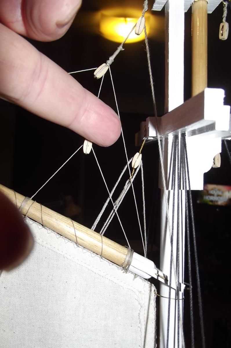
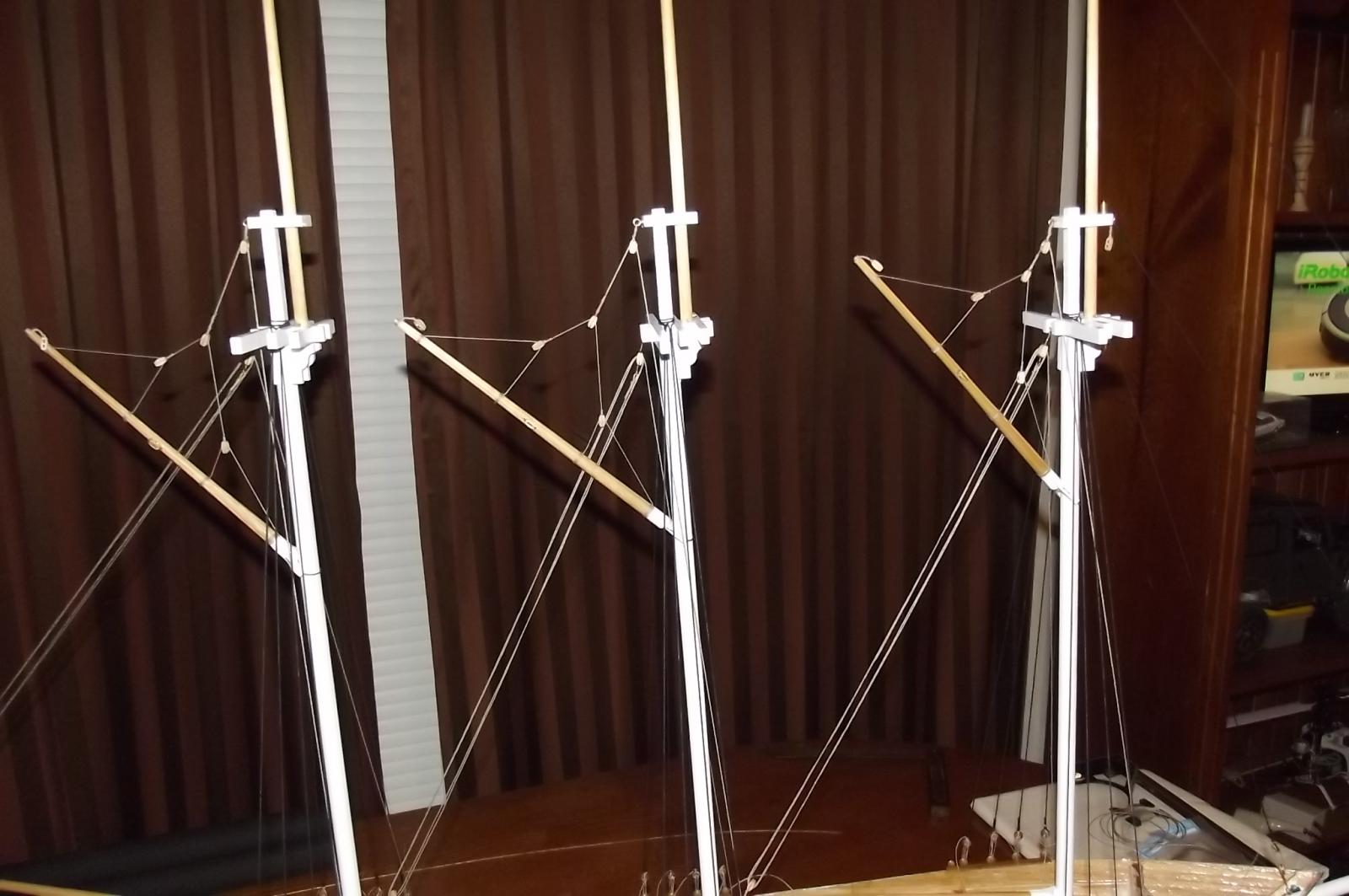
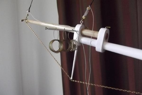
John I have thought of all of that but will always try the easiest solution first and by placing the lanyard between the master block above the gaff and the yolk and moving the down haul forward of centre I have found the centre of force required to make the gaff come down evenly. I still have a few drag issues with some of the hoops and may go for 1mm brass wire instead of 0.5mm as this would present a larger diameter rubbing point and being heavier should help too but I have even considered having a haul down line for the hoops. I think if it came to that I would give up on the idea though. This is the challenge I set myself so I must cop the greif and work through it.
-
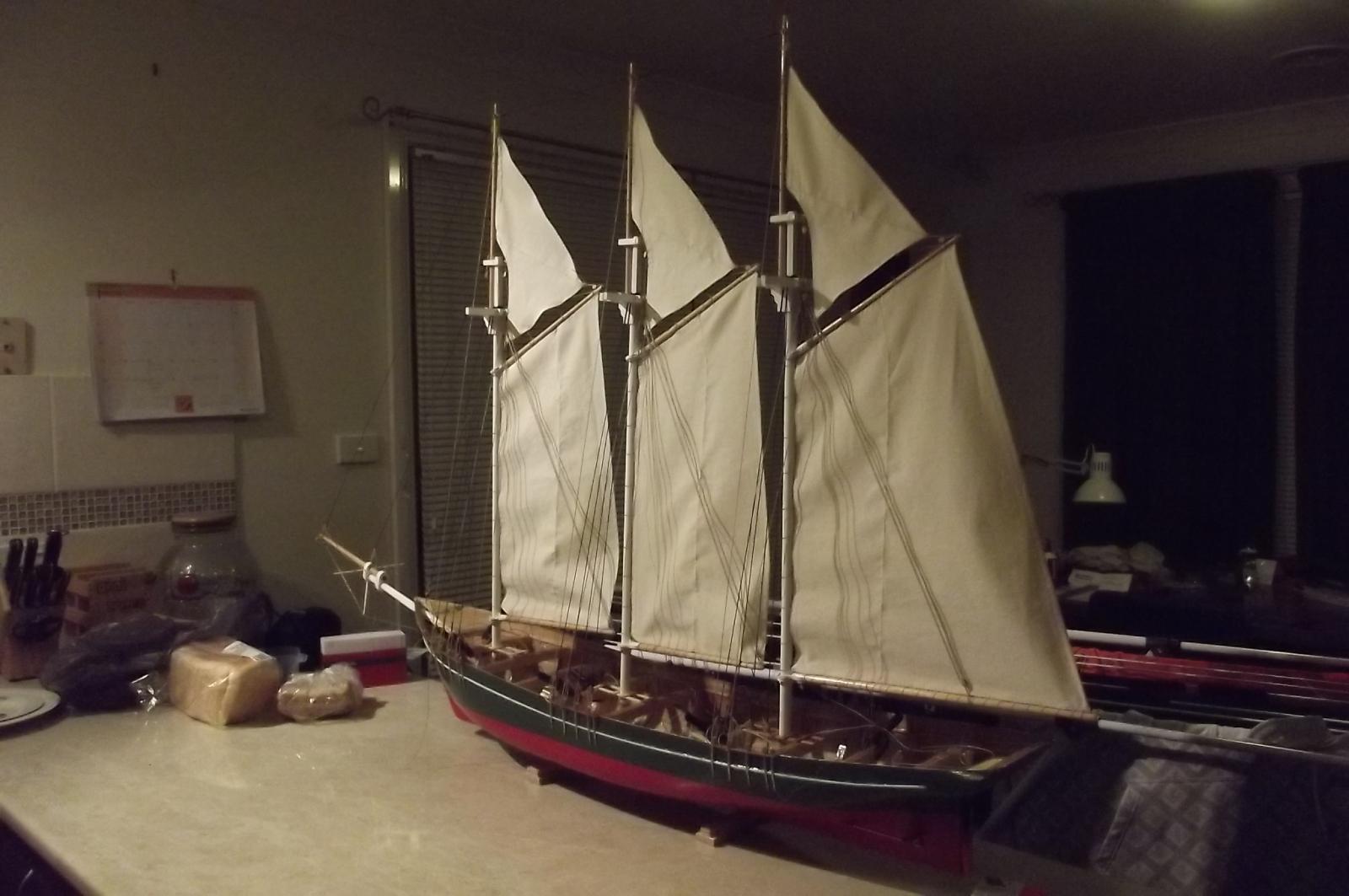
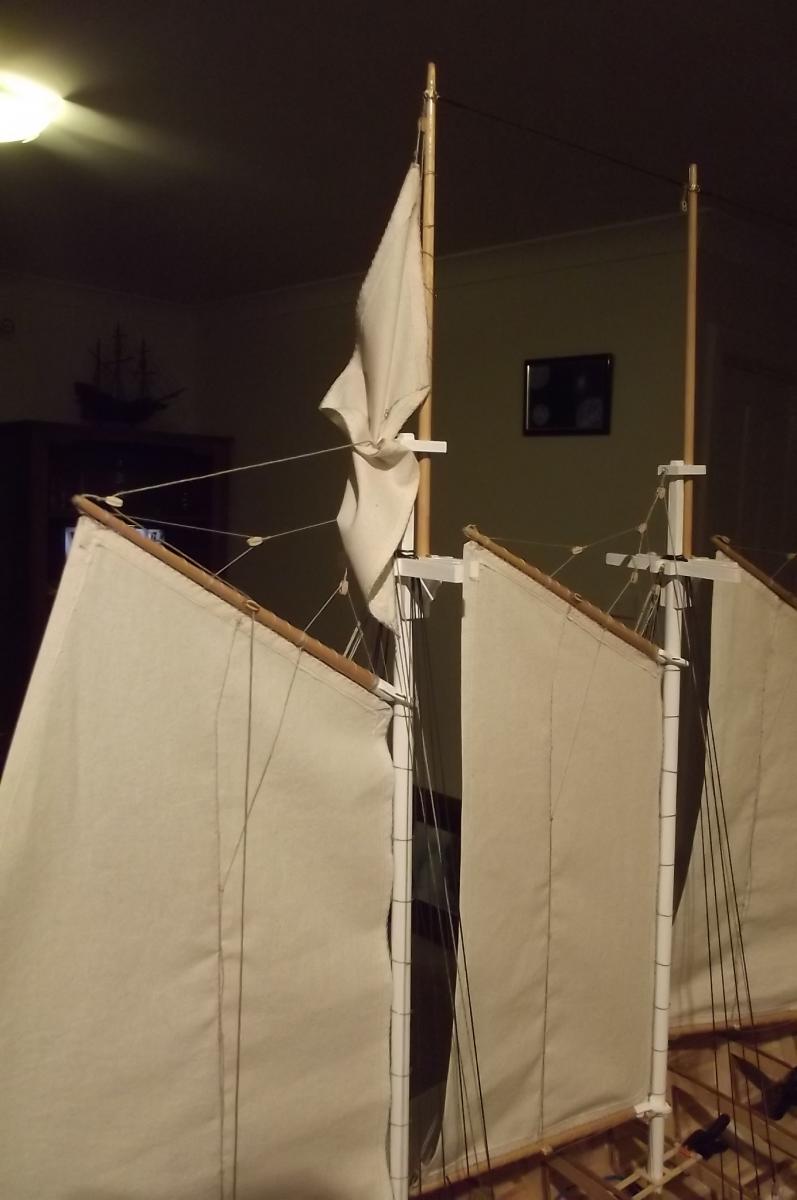
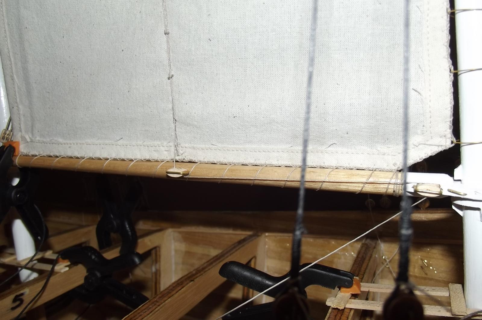
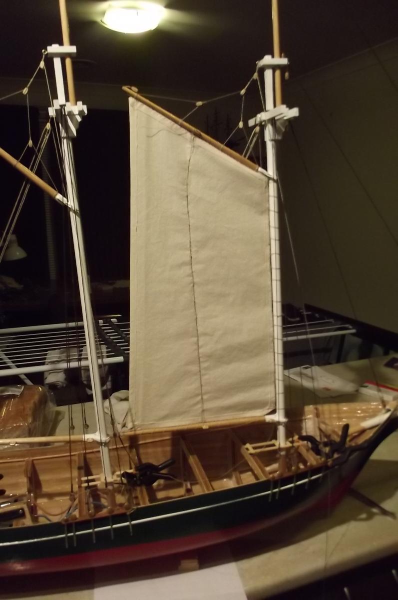
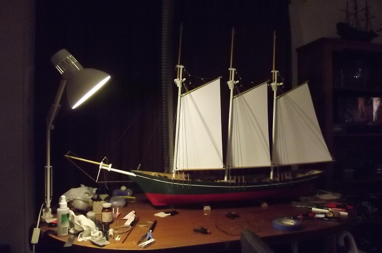
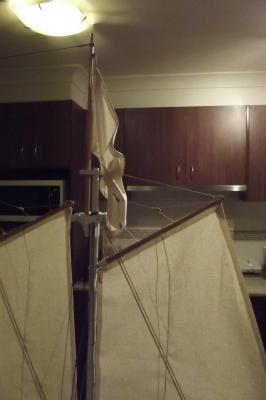
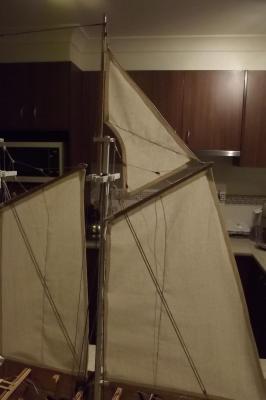
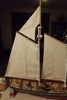
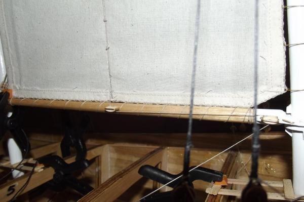
Ahh so that's a clapper. I was thinking of lining the rubbing edge of the yolk with a brass wire to reduce friction but my son and I put some thought into it and came to the conclusion that the best way to reduce friction is to reduce the number of items causing friction so I removed half of the hoops so now there is one every 40mm instead of every 20mm and this has helped the sail itself go up and down the mast. Then instead of running the lazy jack through loops every 20mm on the sail I reduced it to just three loops, this dramatically reduced friction there and while the sail is not as controlled as it is hauled down it is still managable. You will see that I also moved the point of attachment on the gaff forward to a point that equalises the down pull so it happens smoothly without the outboard end of the gaff heading down first which caused the yolk to jam on the mast. The other step was to add a lanyard from the master block on the gaff halyard to the yolk on the gaff, this ensures the gaff pulls up at the correct angle, again, preventing it from jamming on the mast. The result is a sail that can be raised ad lowered very easily.

-
I was always concerned that these issues would arise but I decided to wait until this point to see how much of an issue they are and what may be needed to fix them. If all else fails maybe the course sails will be hand set but we will see. Now to google "clapper"
-
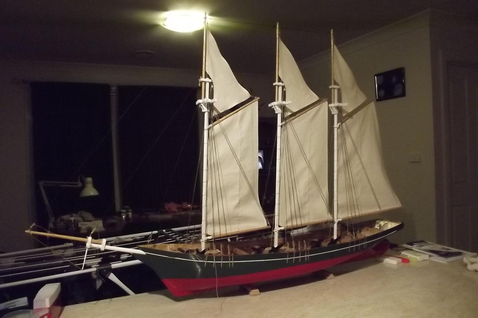
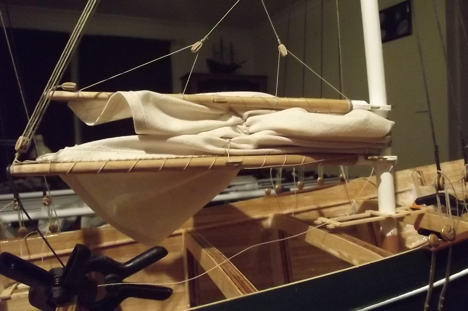
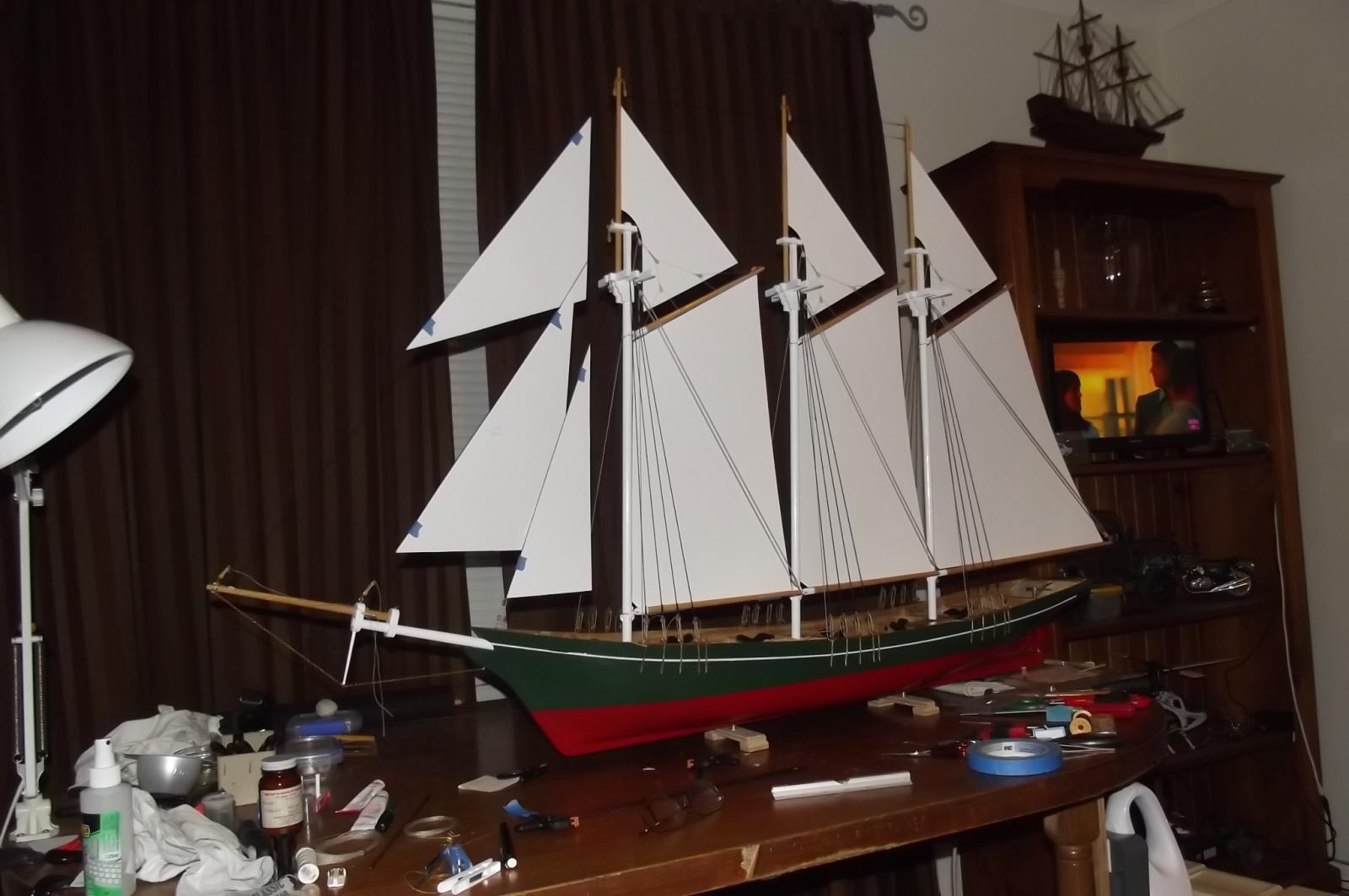
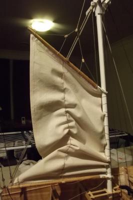
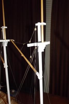
I have attached the first sail and tried raising and lowering it. You can see the lazy jack, the line that hauls the gaf down and gathers the sail in the process. It passes through loops sewn into the sail at 20mm intervals. It all looks good but the gaf won't travel evenly on the mast because there is too much friction so it goes up too steeply and binds and does the same coming down. The other problem to arise is that the boom is nowhere near heavy enough to hold the sail down when it has wind in it so I will probably have to find a way to stay the boom to the mast to maintain the correct angle. These pics are with the fan on.................wind in your sails!


-
Thanks for the link Bob, it reminded me, I only ever found womens clothes when I searched for supplex. I have added the link to my favourites under model suppliers for future reference. If I was to use it for sails I would have to go for "nude" because I just can't put stark white sails on a tall ship. They had canvas and canvas was never stark white.
-
Very interesting Jerry. I did try to find suplex but no-one knew what it was and online I kept comming up with something else from memory. I therefore went back to the cotton cloth idea. It should be supple enough to gather when I hall down the sails ( I hope ) She may not sail very often either but I have kept the sail templates so I can always make her a new set should the need arise. I will be hand stitching all and sundry to ensure nothing goes astray. Steve
-
For a fee John, a BIG fee
-
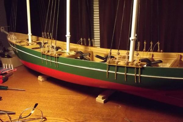
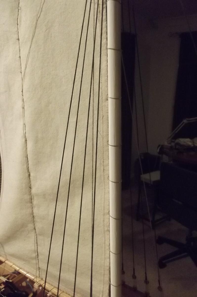
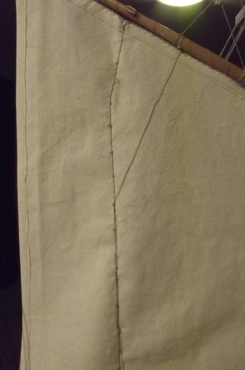
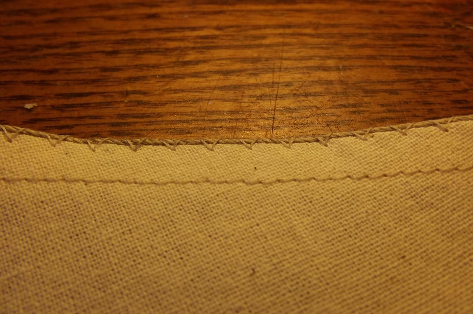
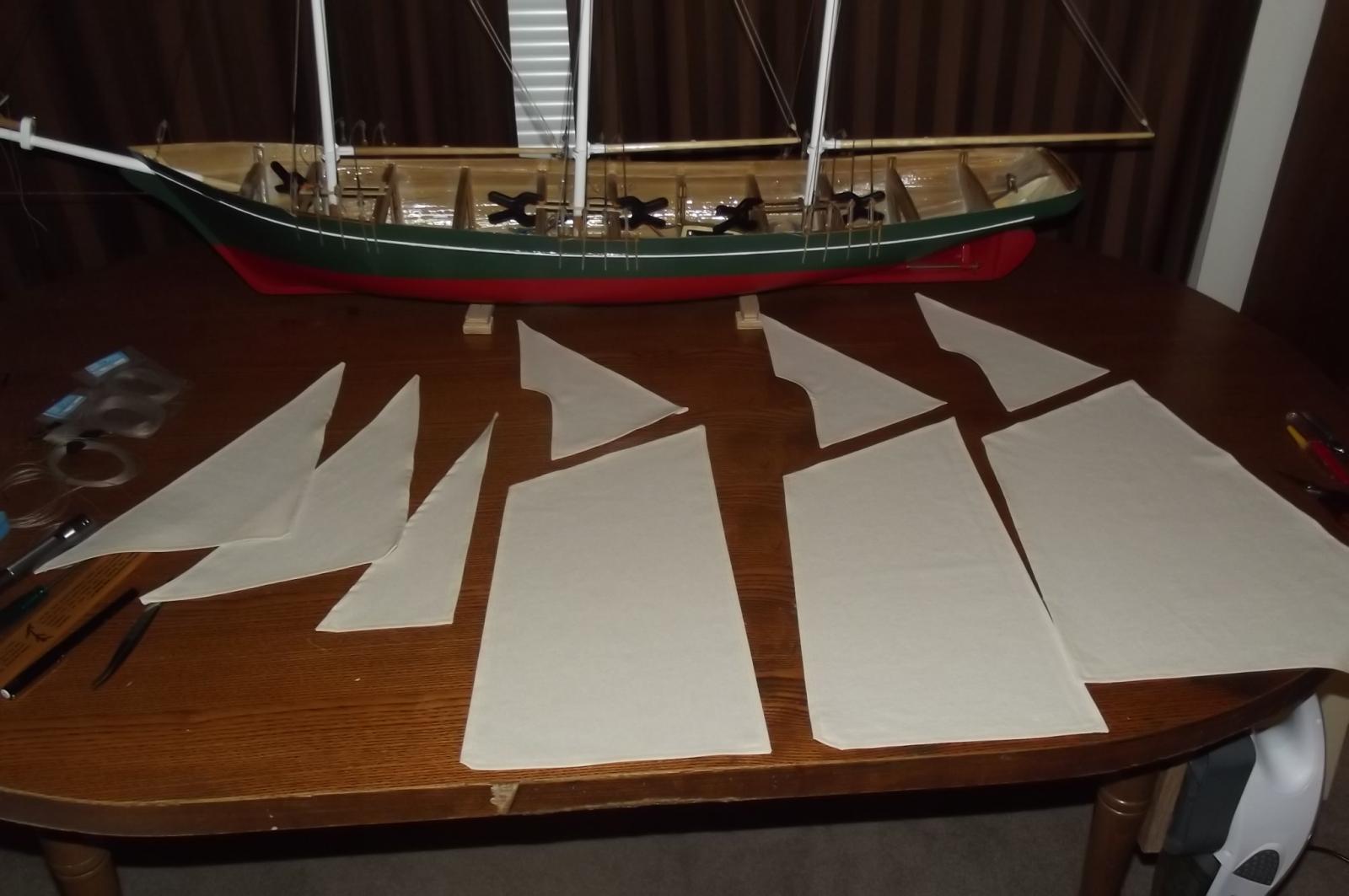
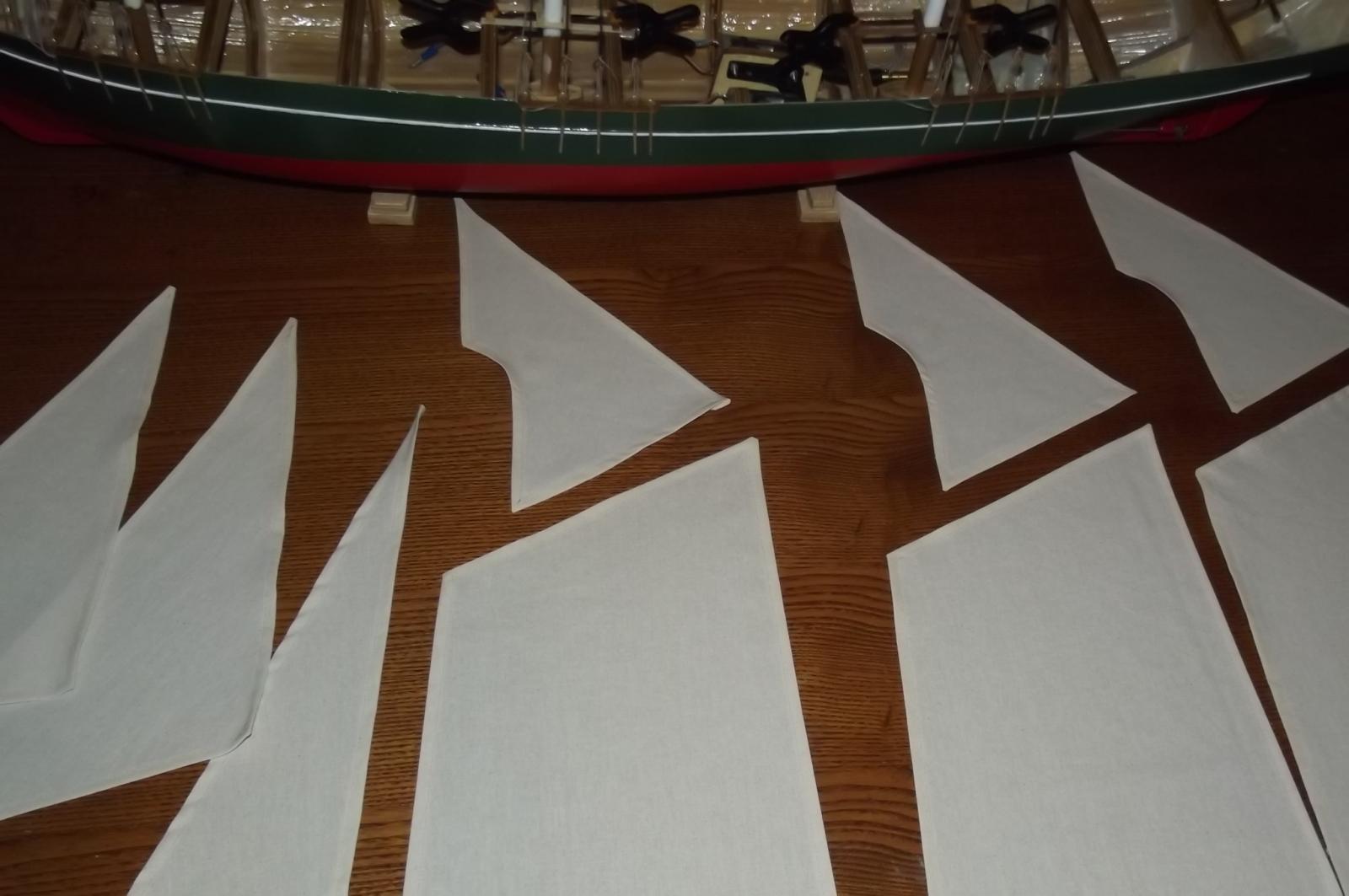
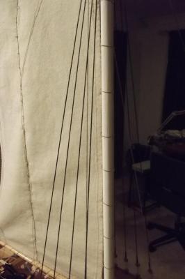
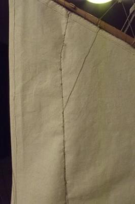
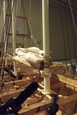
I was dreading the hand sewing that would be required to attach the bolt ropes to the sails so I thought about it and decided it was worth trying to do them on the machine with a zig zag stitch. I tried and failed a few times on scrap sail fabric, the main problem was that the machine process seems to stretch the fabric a little while the rope does not stretch, result, puckering right along the edge of the sail. After some thought I decided to try a wider zig zag stitch that would reach completely across the rope without stitching through it. This worked beautifully and because the zig zag just encases the bolt rope I can just draw it through the stitching until the sail pucker is gone. It worked a treat. Unfortunately I have ran out of cotton with two tops'ls to go and I have yet to stitch the guides for the lazy jacks into the sails. I figure I will pin a cord to the sail where I want the guides to be and stitch it to the sail with a tighter zig zag stitch. Then I can just pull a small amount through and create a loop at intervals up the sails for the lazy jacks to go through. Again I need more cotton to do this so the sail maker has gone home for the day. I have also made the mast hoops. I used up all the 0.5mm brass wire I had and got 16 hoops per mast which should put one every 22mm. I need more wire for the tops'ls. I made the hoops by wrapping untempered wire around a steel bar of the correct diameter and then using pliers I twisted the ends of the wire together through 180 degrees and then cut the tails about 1.5mm outside the twist to form two interlocking hooks.

-
I'm back on board. Keep it comming.
-
The machine work on the sails is done. Next on to the hand sewing.

-
Absolutley amazing! how long is she?
-
Yeah thats the plan, busy making other sails for now though.
-
You're right Jerry, On the half scale drawing it looked ok but once I put it up there I thought the same as you. Nothing is concrete yet so I will work on that.
-
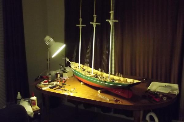
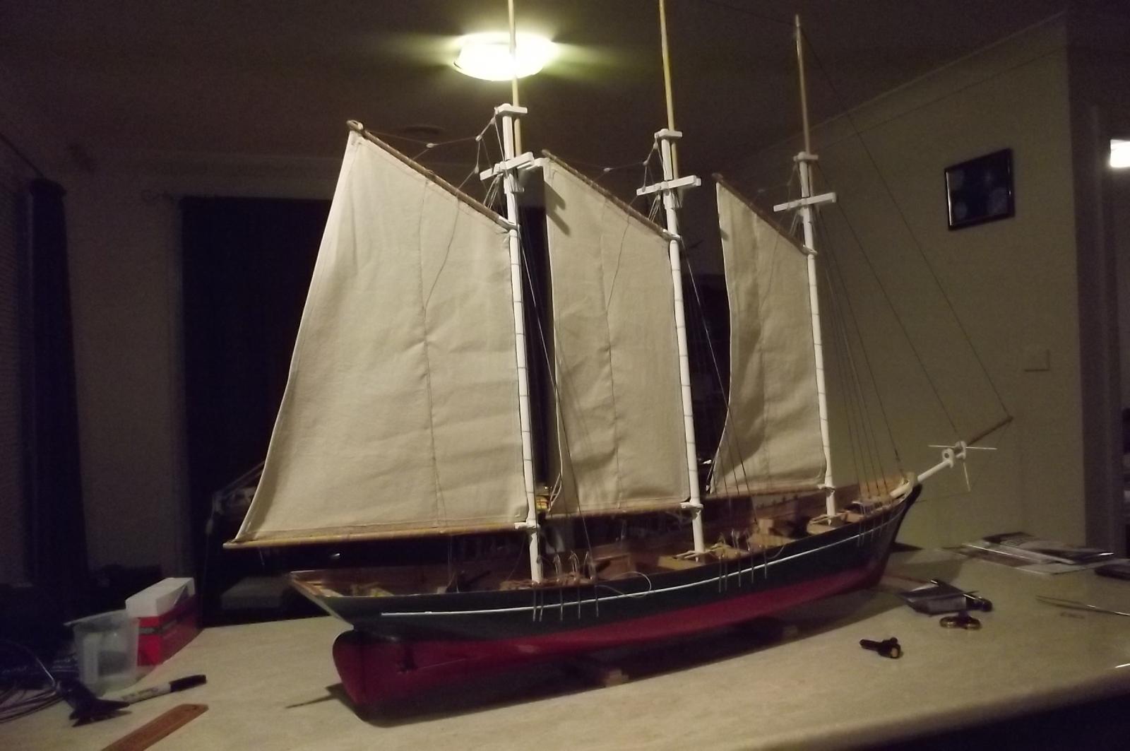
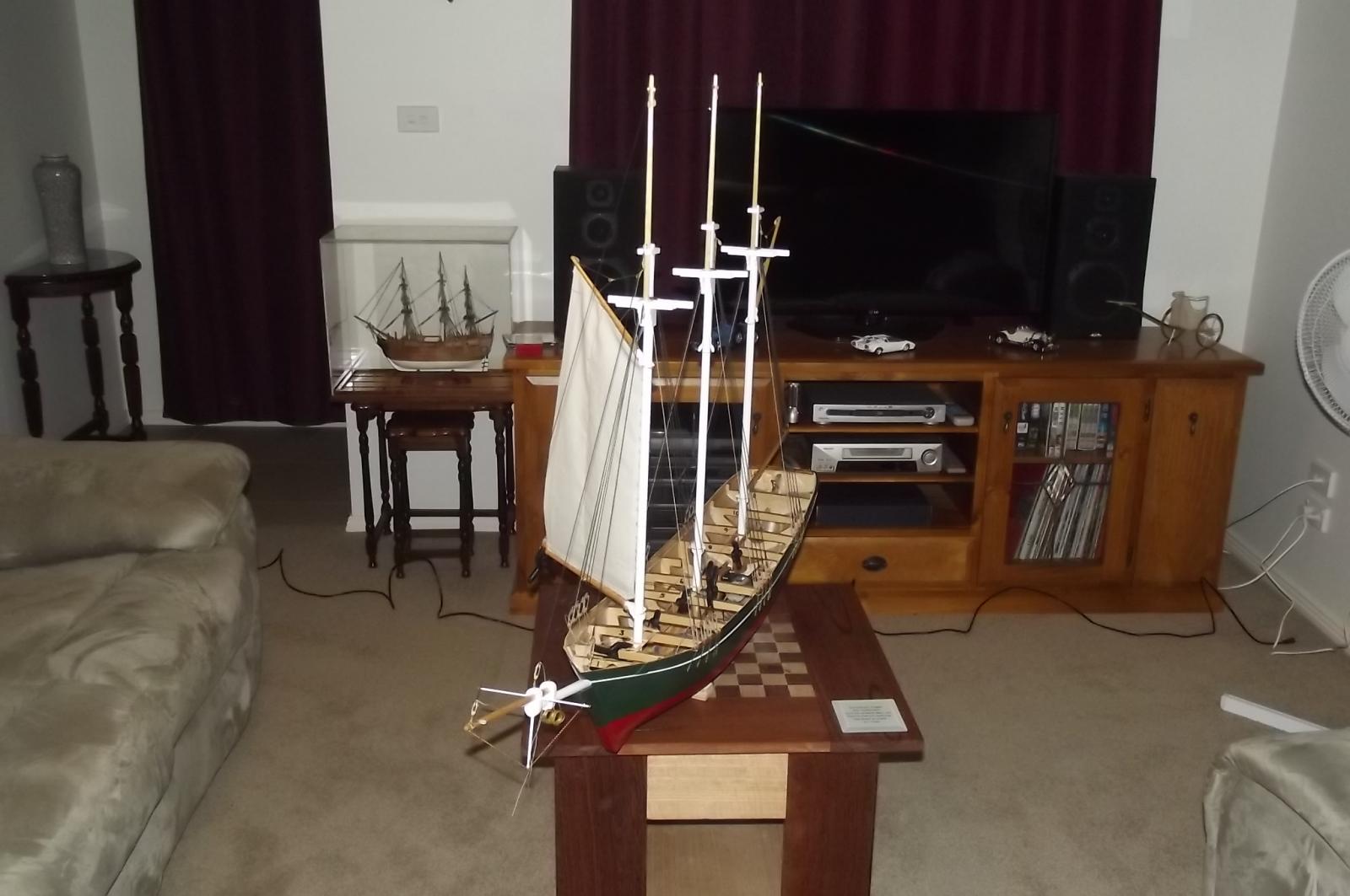
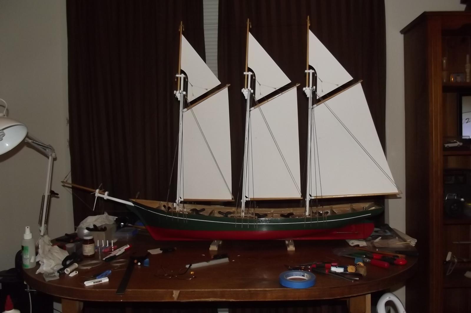
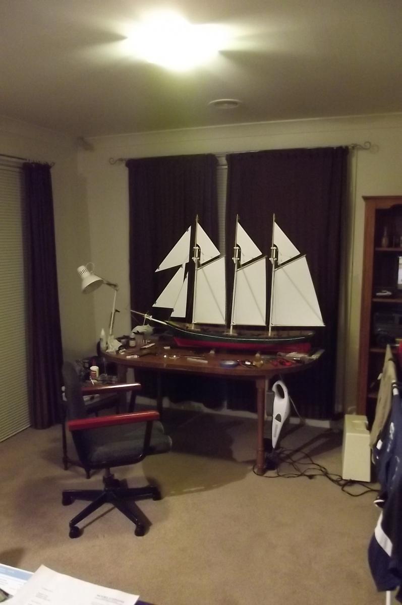
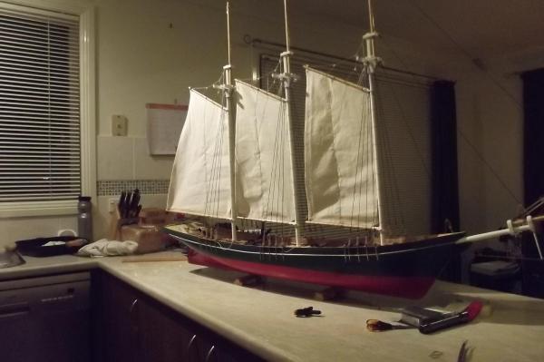
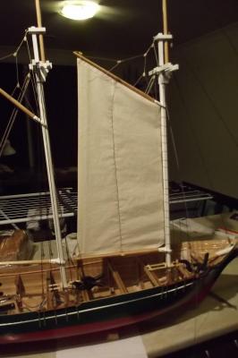
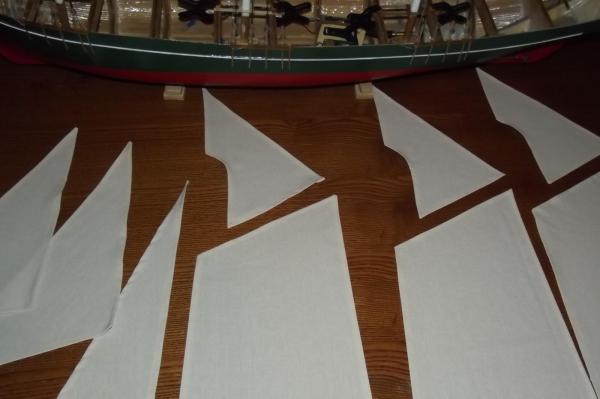
I have made the sail templates to make sure it all fits, next job is to make the sails and see if I can get them to work the way I want them to. Even though the sails are just cardboard it looks magnificent, I think it is going to look brilliant under sail. I am hoping this pic will give a good idea of it's presence in a room


-
Batavia by *Hans* - FINISHED
Bedford replied to *Hans*'s topic in - Build logs for subjects built 1501 - 1750
Don't forget the soft ropes with the frayed ends that dangled in the water so they could pull them up and wash their backsides when they finished. -
I've been a little bit busy over the weekeknd. I think the next step will be to make sails.

-
Long way to go yet Bob, better get stuck into the Lettie to pass the time.
-
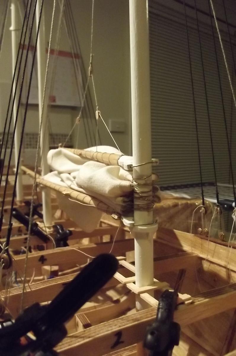
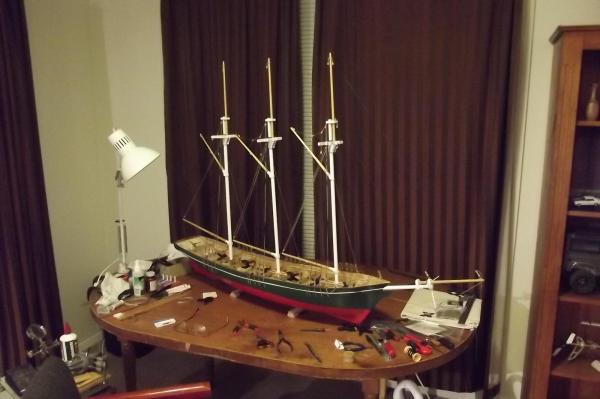
Shrouds are on, I don't think I need to do the top shrouds because the top masts are stable enough to mount the running rigging etc so they can wait til later. As a side note I calculate a bit over 1400 knots in the rat lines! Once I re-learn the technique they are pretty quick and easy.