HOLIDAY DONATION DRIVE - SUPPORT MSW - DO YOUR PART TO KEEP THIS GREAT FORUM GOING! (89 donations so far out of 49,000 members - C'mon guys!)
×
Bedford
-
Posts
1,297 -
Joined
-
Last visited
Content Type
Profiles
Forums
Gallery
Events
Everything posted by Bedford
-
 Mate, I may not be building rc either, that remains to be seen! It's all a case of the blind leading the visually impared at this point. As I have said before IF I build another such vessel it will be done VERY differently. But I do have a subject in mind....................
 -
That's the joy of scratch building isn't it? Nicely done.
-
Such a huge effort, she looks brilliant, can't wait to see her sail
-
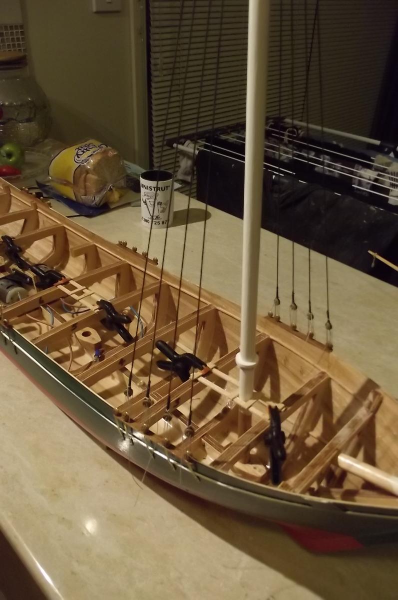
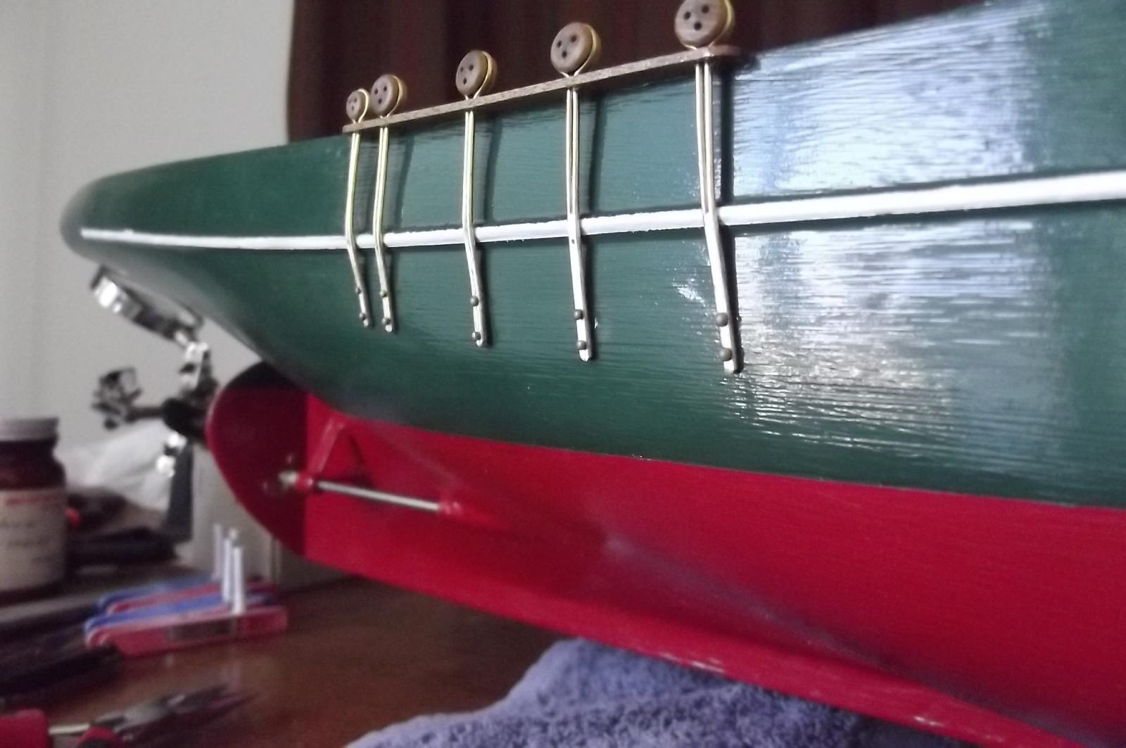
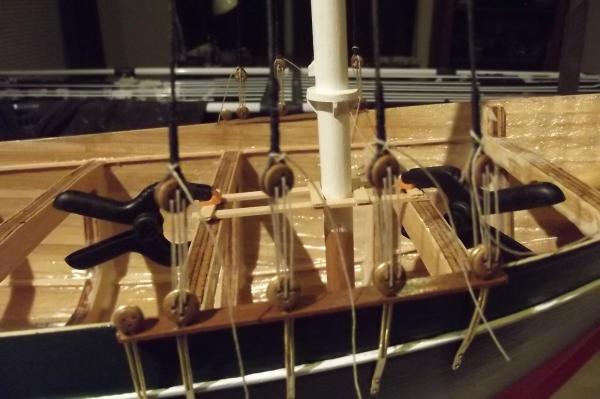
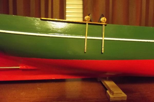
Elementary my dear Watson/Watsonette. I have to get all the running rigging set up and working before I can close the deck, hence the standing rigging as it holds the masts in their correct location and provides anchorage for the stays'ls. Once all is set up and working I will unship the masts and rigging and finish the deck and deck furniture then re-fit the rest. It isn't a big deal to loose the lanyards and remove it all. Back to the chain plates, the white line is level with the deck so when you think about it they aren't that long really, just over 2mtrs at full scale with only half of that below deck level.
-
Progress

-
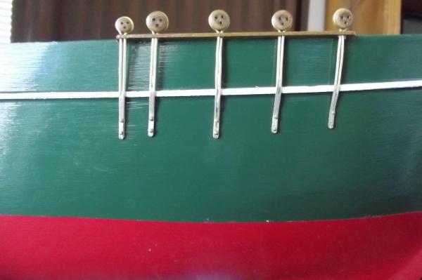
Robbyn, going off the plan I am working from they are a tad short. I made them that way to keep the holes out of the water as much as possible. Not that the few mm I cut off will make much difference. I am guessing they were long because the later ships really pushed it and they needed to be as strong as possible so the further down the hull they reach the better.
-
Batavia by *Hans* - FINISHED
Bedford replied to *Hans*'s topic in - Build logs for subjects built 1501 - 1750
The Batavia may link us more than you realise. Among the punishment handed out to the mutineers was the sentence of being put ashore on mainland Australia and left here. This happened to a few of the mutineers so they were the first penal colonists of this country, long before the English started sending there criminals here. It is said that when the English colonists reached the central western coast (around what is now Geraldton) they encountered a few blonde aboriginals. Descendants no doubt. On a side note, although it would have been very hard going for the early convict settlers I think we got the better deal in the long run. Sun, sand, good weather, gold. Thanks England -
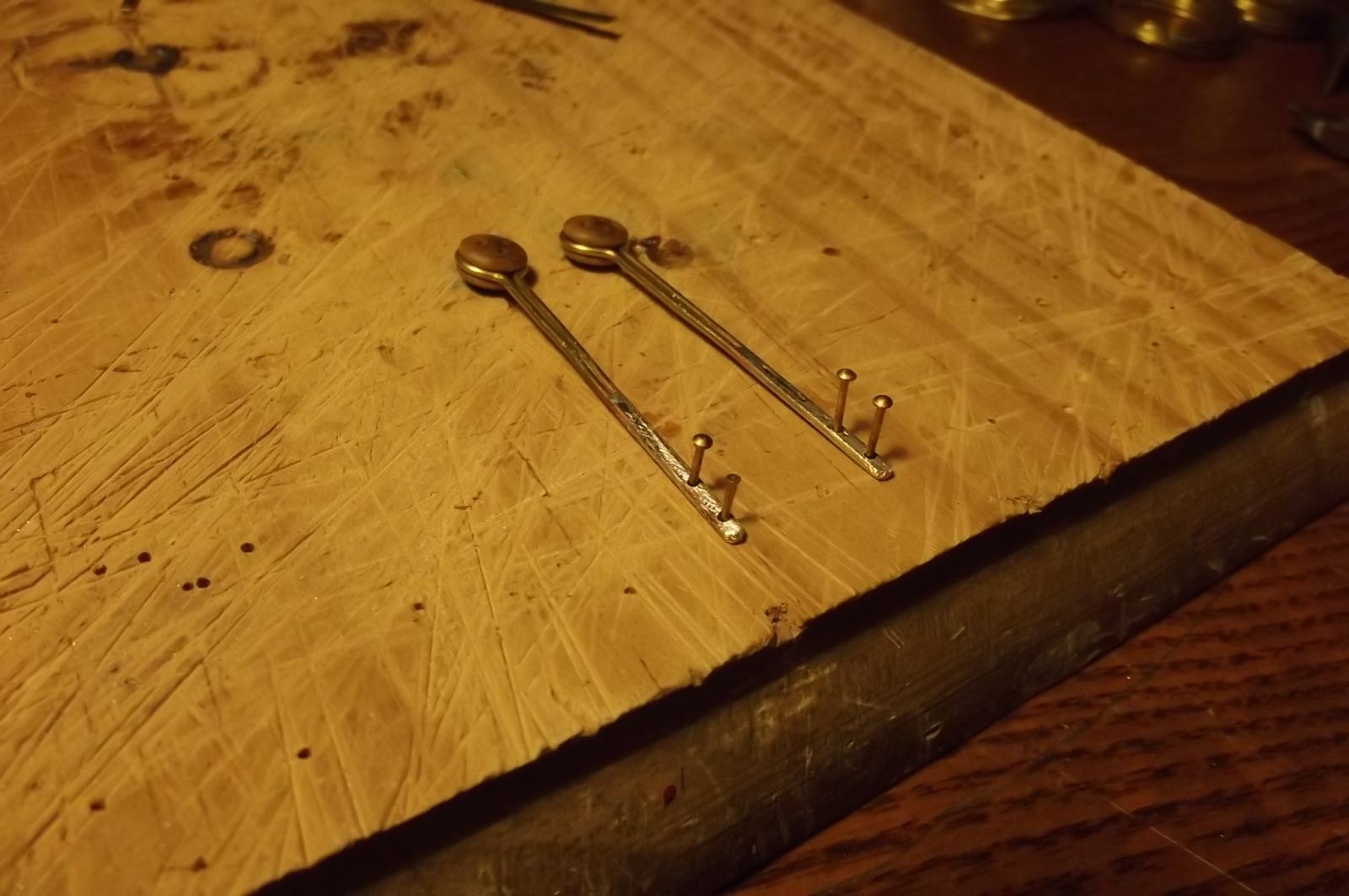
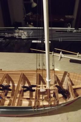
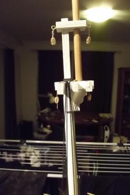
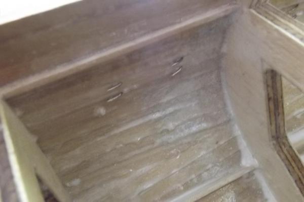
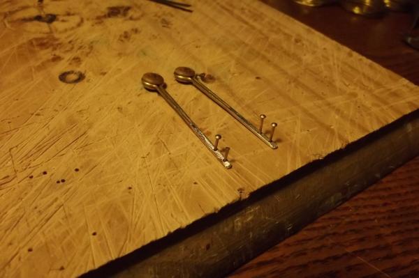
Chain plates To get the correct angle on the chain plates I fit the masts at the correct angle and run a line of cord where the shroud will go, I centre it over the dead eye and continue down onto the hull. This shows where the chain plate needs to attach in order to get the straight line with the shroud. In this case I then drilled two 1mm holes through the hull using the chain plate holes as the template. I then used a magnet to weed out the brass plated steel nails from my nail tin and selected 60 long brass nails which were then annealed to soften them for bending. Once all that had ben done I mixed a small amount of epoxy and put a blob (technical term) on each hole on the inside of the hull for one station at a time, ie starboard mizzen chain plates first. I then pushed that through the hull with my finger so I had a small sphere of epoxy on the outside of the hull at each hole. This ensured the hole was filled with epoxy to ensure water could not get into the wood. Then I place the nails through one chain plate and while pressing them firmly against the hull with my thumb I used pliers to bend the inboard end of the nail over to form a rudimentary rivet. When all are done I will apply some thickened epoxy over each of these to ensure it won't move or foul anything and it will be water tight.

-
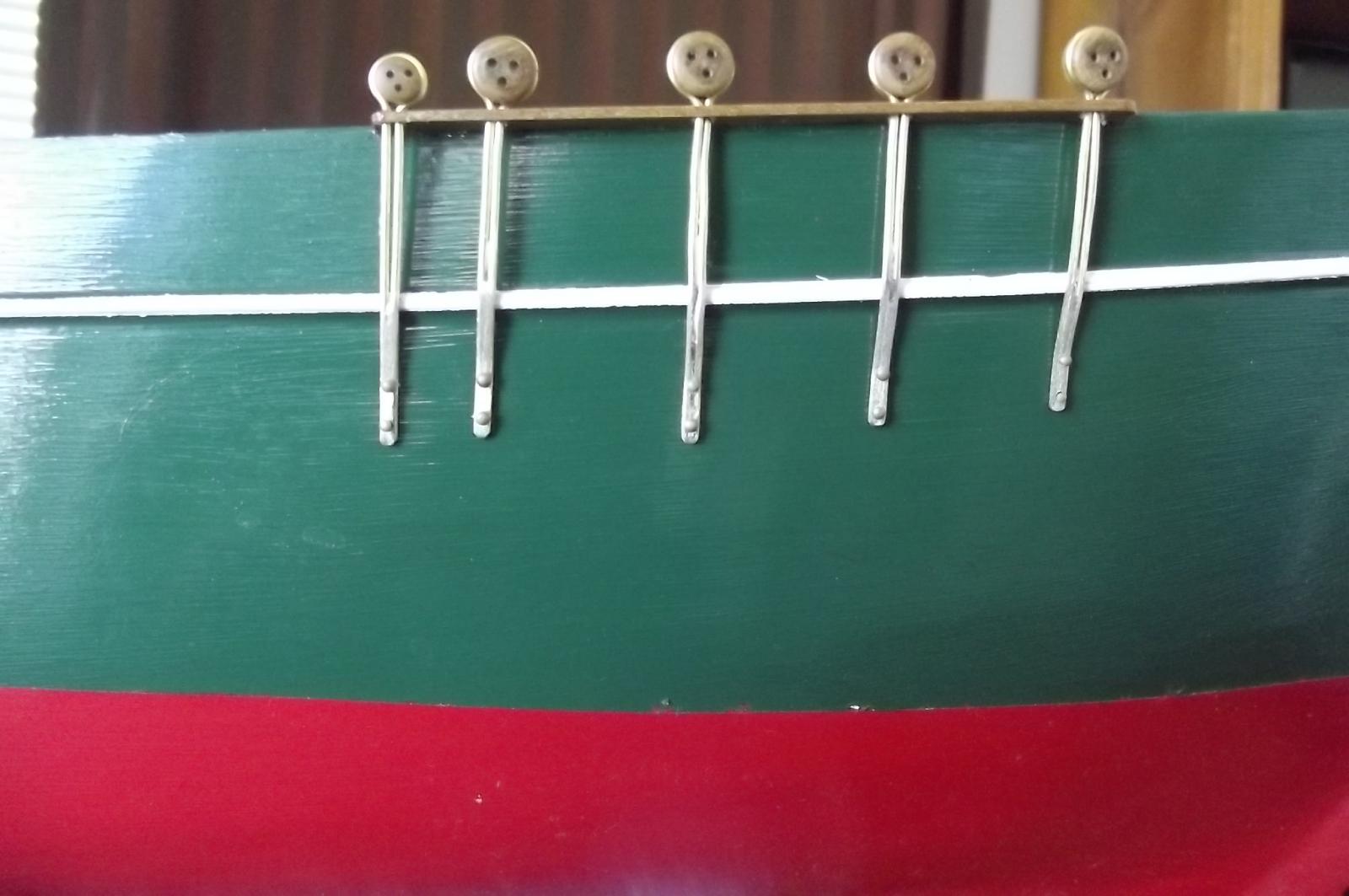
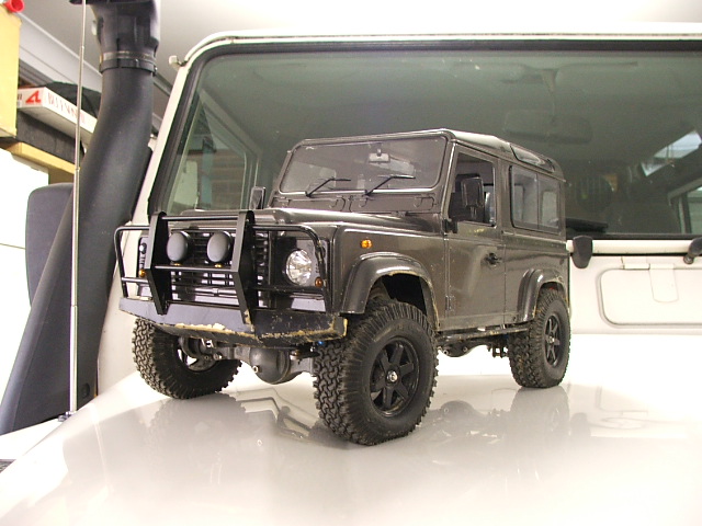
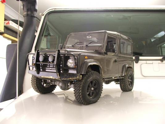
I tried to come up with all kinds of fancy ways of doing them, partially because I didn't trust the solder to hold them in the way I have ended up going. But I used 40/60 solder instead of the softer 60/40 and they seem to be quite strong. So I went with the K.I.S.S. method you see in the pics. I should have realised the 40/60 would be strong enough after I made the bull bar pictured for my RC Land Rover, It is all brass and 40/60 solder and I can pick the vehicle up by the bullbar and it weighs 3.5Kg!
-
I have tried a few ideas and come up with a suitable chainplate that will look the part I reckon. Mass production tomorrow.
-
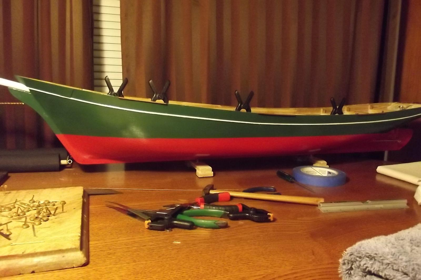
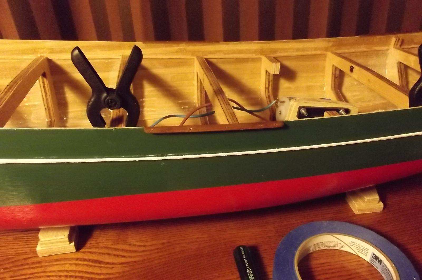
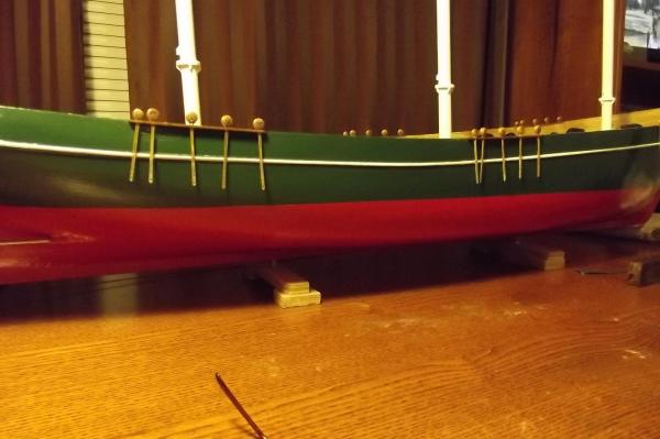
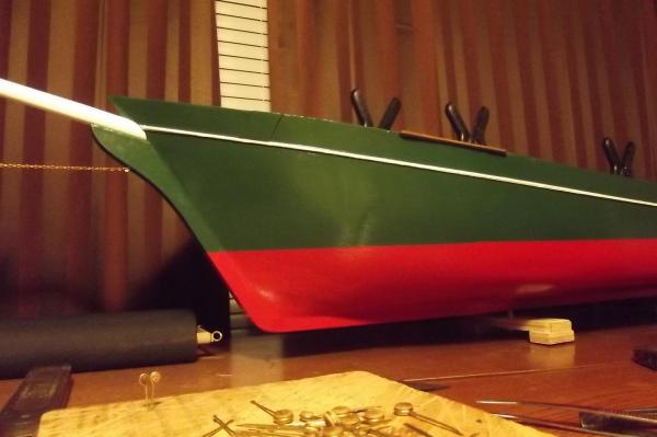
It does define her lines very nicely. Funny, I have always thought it was missing something and then after not working on it for a week or so it just screamed for that stripe when I went back to it.
-
It's been a while, no reasons, no excuses, I just haven't felt like doing anything with her..... I am in the process of making chain plates but had to get more brass to do it so while waiting I fitted the shroud tables and realised that she looked a bit unfinished in the hull. Then I realised she needed a stripe.


-
Beautiful work Michael
-
Batavia by *Hans* - FINISHED
Bedford replied to *Hans*'s topic in - Build logs for subjects built 1501 - 1750
And he slips in a semi nautical reference, "You ain't Robinson Crusoe" -
Batavia by *Hans* - FINISHED
Bedford replied to *Hans*'s topic in - Build logs for subjects built 1501 - 1750
That's not much really when you consider the James Craig cost $20 million to restore. It is all relative though. Steve -
I agree with the new compass placement, it just looks right!
-
Lovely work Michael. No radio eh? Brave man, that! I would never have the intestinal fortitude to do that. Steve
-
Standard procedure Robbyn, the trick is to get all the wall side stuff on the same side. It usually tends to work out though.
-
More hold ups, I got my dear old mums' old sewing machine out to try my hand at sail making and it didn't work, I could not get the bobbin working. I reasoned that dear old mum had no mechanical aptitude at all and she could do it so I must be over thinking it. I asked a lady friend to come and see what she could do with it but she had no luck either. Tonight I started pulling it apart and bits of the bevel gear that drives the bobbin fell out onto the table. That's terminal in a 40 year old machine so I will borrow the afore mentioned friends' machine. Michael, you were talking about all the things you saved over the years and while I try to limit the amount of bits I keep, the macine is full of cams, gears, shafts, specialised screws and a good healthy motor and speed control unit. I will be stripping the machine out before I toss it.
-
I'm with the "I have to remind myself it isn't full size" brigade. I aspire to this level of build but fear I just don't have the patience. Steve
-
Batavia by *Hans* - FINISHED
Bedford replied to *Hans*'s topic in - Build logs for subjects built 1501 - 1750
I have seen the stern section in the Freemantle museum and been aboard the replica when she was in Sydney at the Australian Maritime Museum. There is a book called Islands of Angry Ghosts that tells the gruesome story of the Batavia as well as the story of discovering and recovering the artifacts. It is a chilling read. This build is quite interesting and I love the stern you have made. Steve -
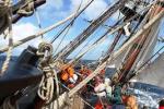
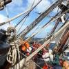
One thing I got from the video is a much better realisation of the size of the model, she will be magnificent under sail
-
I have been otherwise occupied for the last few days, yesterday I was just about to start work on the schooner when my son knocked on the door and said "wanna come 4wd'ing" uuuuuuuuuuummmmmmmmmmmmm, yeah! Only 10 mins from home is a nice place with plenty of variety but I didn't get home til 7:30 and was a bit tired so didn't touch it. Today, on my way home from work and my son rings, "Dad, can you do me a favour"? mmmmm, what? "Come and get me unstuck" He was about 20K's out of town up a track he should not have attempted on his own and I had to winch my car around his so I could winch him out, 3.5 hours after I left work I got home! No work on the schooner tonight either ! Wish me luck for tomorrow.