
Bedford
-
Posts
1,299 -
Joined
-
Last visited
Content Type
Profiles
Forums
Gallery
Events
Everything posted by Bedford
-
 Right, it is a dog clutch. It all makes perfect sense now. Can you tell I love old mechanisms?
 -
This is a beautiful mechanism, simplicity and elegance. I get how all of it works except the "spline" made from the socket head screw, what's that about?
-
Inventive work, I love it. You find what you want in other things like the socket head screws, brilliant! The gearbox mark 2 looks very good, nice and smooth too.
-
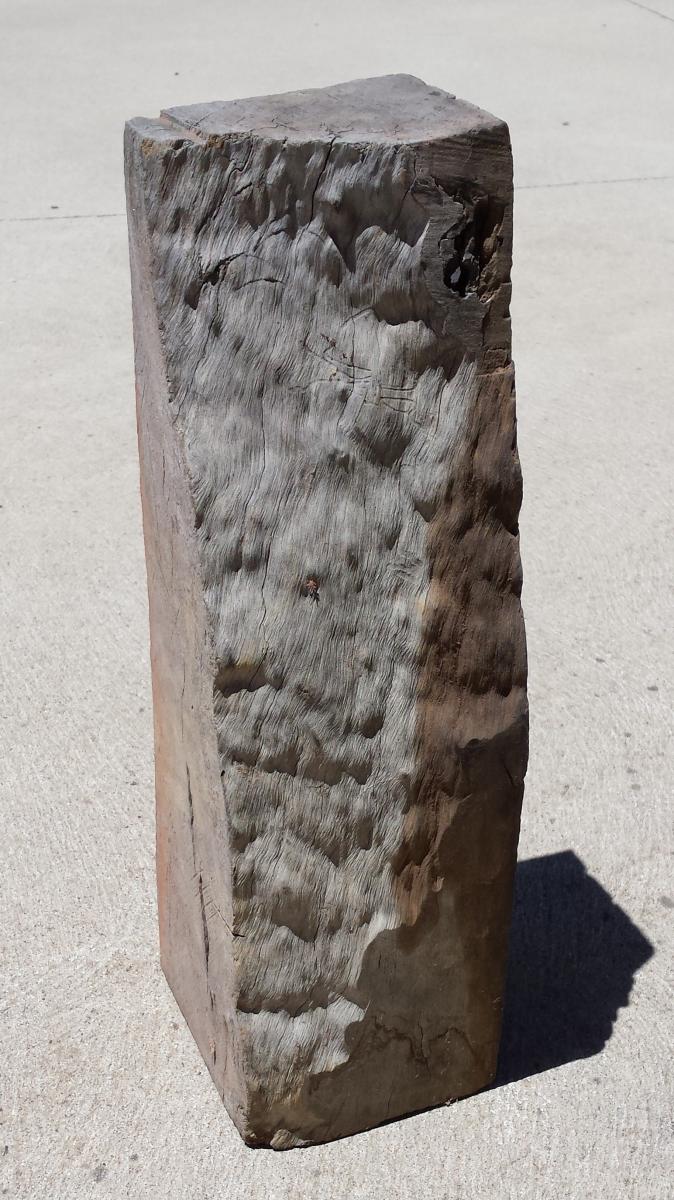
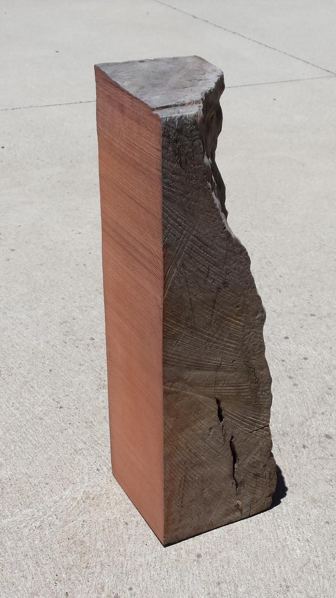
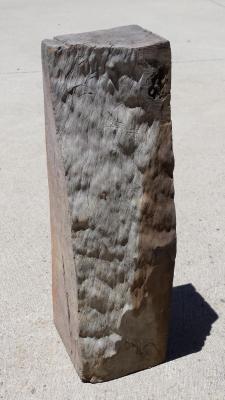
Well John, I started with a brand new blade and it did the job just fine, it has dulled the teeth a little bit but I am impressed. Got the blades from an ebay manufacturer in QLD. I did try and get lose dirt of the exterior before I started because that will blunt a blade in the blink of an eye. The grain is so fine that the saw dust was just that, dust! I sanded it with a belt sander in coarse grit then medium before finishing with 400 grit open coat on the orbital sander and as that wore out it polished the timber to such extent that it had a reflective finish before I applied the wax. It looked almost like a man made resin artificial timber. The wax just brought the colour out a little better. It was a joy to work with in this scale, I have used it before. I turned the pedestals for my Schooner for Port Jackson from it and the top of the capstan on same but you don't really get to appreciate the beauty of it on such small items. When handling it I was reminded of the piece of Lignum Vitae I once had the pleasure of handling at the old Sydney Maritime Museum, not quite as dense or heavy but not far off and almost as smooth.
-
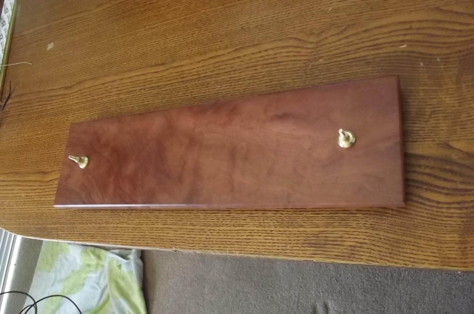
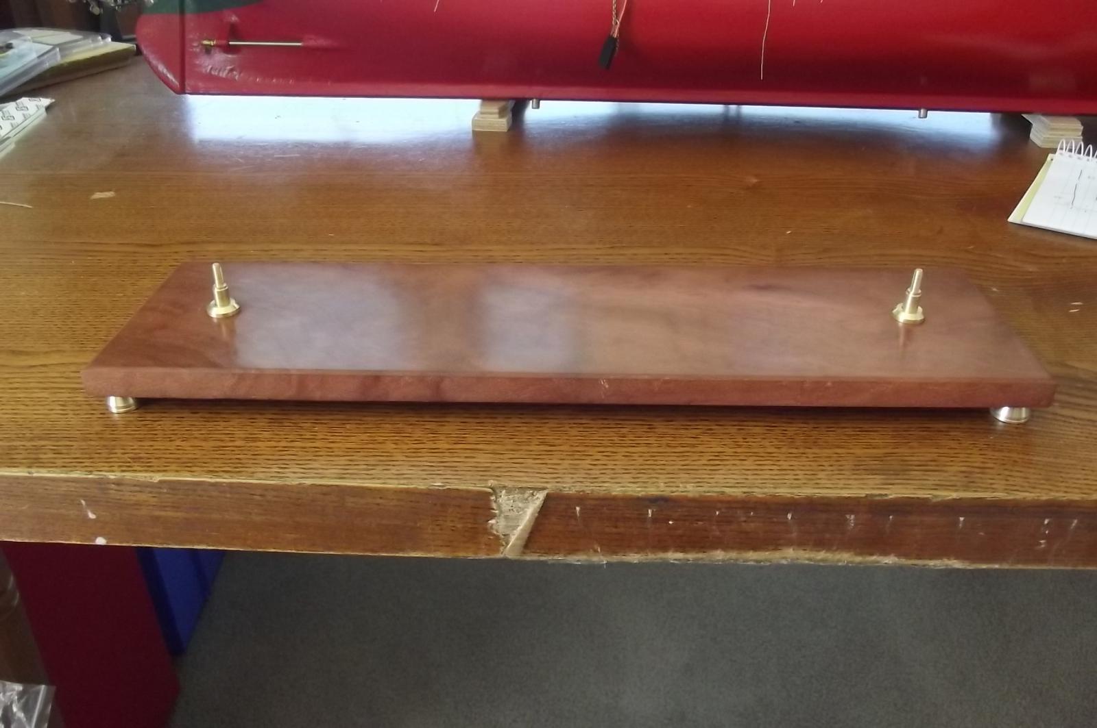
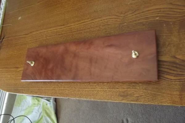
I have walked away from the technical side of this build for a while and it was so nice to just make something for her in the workshop. First, take one very old block of river red gum (I've had this for a quarter of a century and it looked like this when I got it so no idea how old it is) then run said block through the band saw.... Do some sanding then add a little dab of this and rub a bit. Add a few bits of brass fresh off the lathe and you end up with this. It really is such a beautiful piece of timber that I didn't need to make it look fancy by giving it a nice shape, just a small bevel around the edge and it looks amazing, the pics can't do it justice! And this is what it looks like


-
Taking shape beautifully
-
Got it ! I was thinking it might work like a differential in a car and it pretty much does, if you turn one axle with the drive shaft stopped so the diff centre can't turn, the other axle will go in the opposite direction. Free the drive shaft and allow the diff centre to turn and both axles go in the same direction. Obviously in this case there is no differential action, just locked and free, reverse and forward Does that sound right?
-
I think I get it Michael, I'm guessing forward involves one pinion "linking" the two gears directly while reverse involves the first pinion moving off the output gear and driving the second pinion which will engage the output gear. I'm not sure my eyes would be good enough to work at that scale.
-
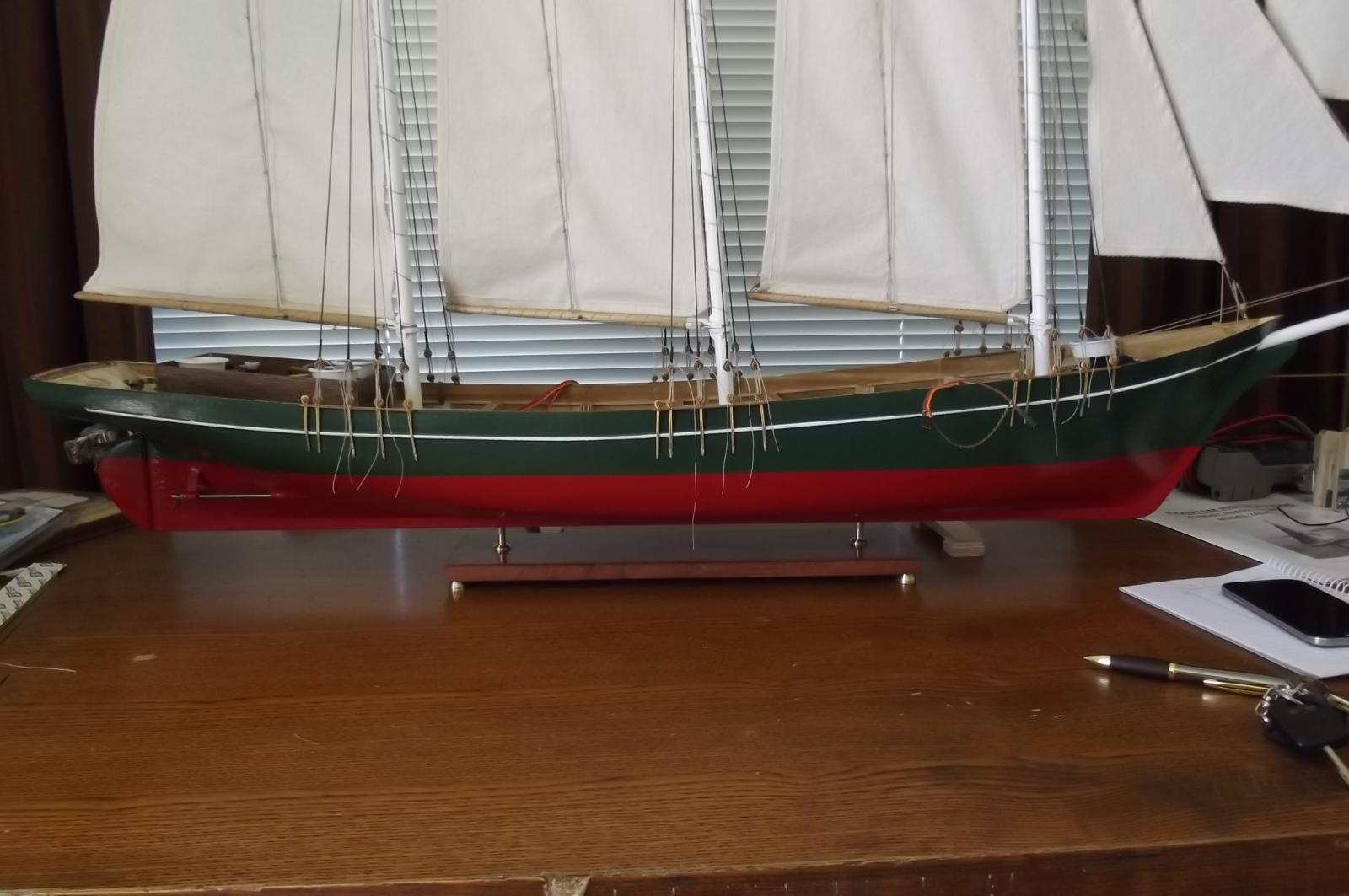
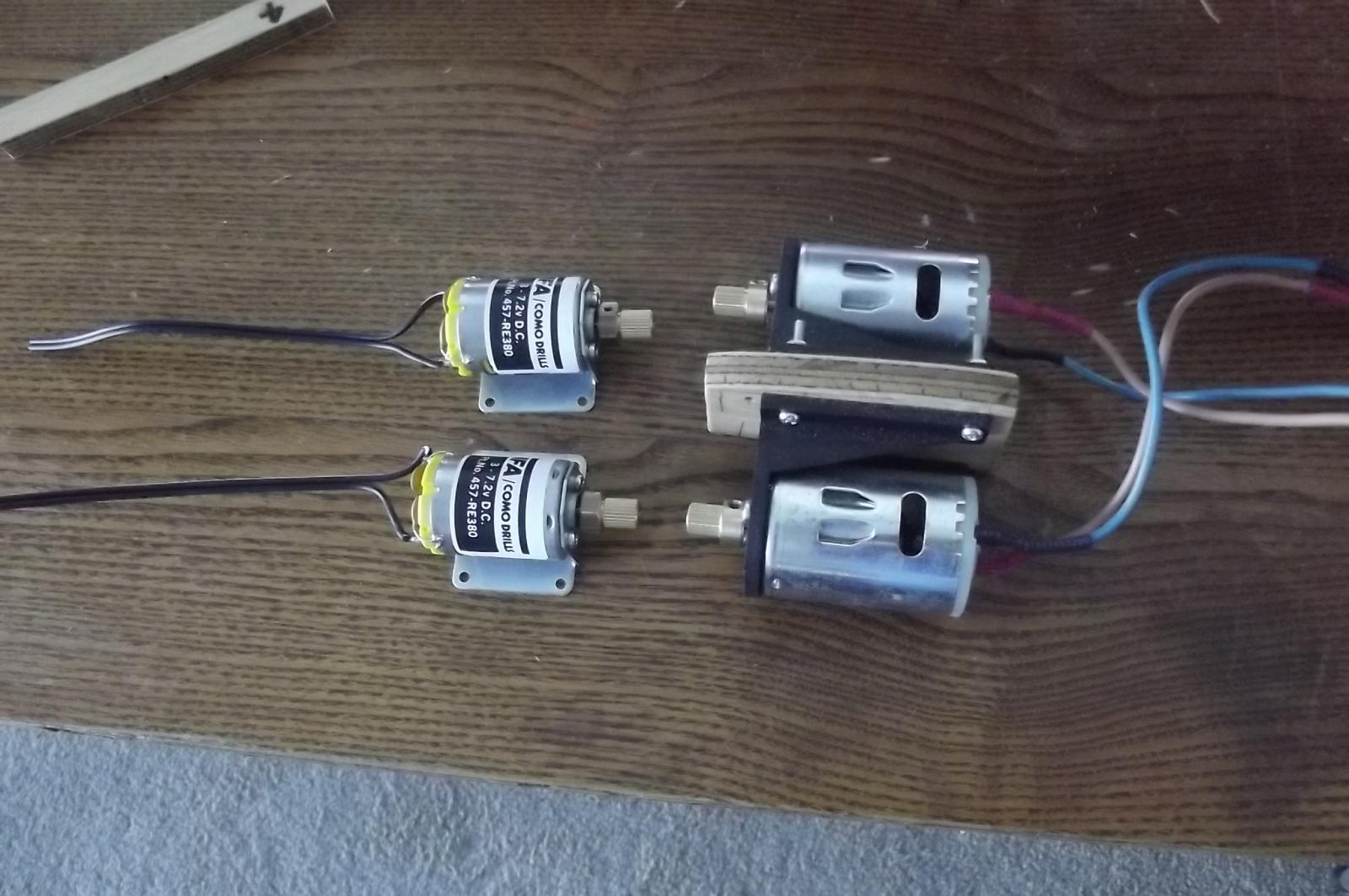
Hey Floyd, DEFINITELY keeping the auxiliary power in the schooner. I just took the yacht out to the lake for a little sailing, took ages to find the right place to launch to guarantee she would be blown back to shore in the event of failure. I launched her and had about 5 minutes of nice gentle sailing before deciding to bring her back because the wind was failing. I just got her on line with enough momentum to keep her inching forward with the aid of gentle rolling waves from astern. I held her for 10 or 15 mins before I thought the breeze had come back but only did one circle of about 6 metre diameter to bring her back due to the wind failing again. This time she almost didn't make it. I packed up and came home. Still, it was a beautiful afternoon to be out there. On a different tack. The new motors and speed controller have arrived from the UK. She will lose 100grams from the stern with these motors which will help raise the stern closer to level while still (I'm sure) having ample power. Now to make a new motor mount.

-
I'm interested in how this bit will come together. There are some things that are worth keeping aren't there
-
Beautiful work as always, the pins are tapered so you only need the put a locking pin through the other end and the taper keeps them in place, is that it? Also how big is the hole through the pin that forms the valve, ie what size hole does the fuel drip through, or are these just for appearances?
-
So are you offering to send them to me, that's very kind of you
-
I didn't think it was possible to make small engines like this run slowly but the leaden flywheel makes it sound very promising, if I'm not mistaken it will also help dampen any wayward vibration that may sneak in. I've moved my chair up the front!
-
Magnificent woodwork, I would imagine your customer was very happy with it.
-
Beautiful work
-
In the case of the real thing I would imagine it is fairly low revving and with the cranks at 180deg from each other balance would be no problem. This engine will have to rev higher I would think but still the cranks are at 180deg and in this case because it all happens so close to the centre line any minor imbalances won't really be an issue either.
-
Michael, you will have heard the expression "to sleep on it" it works and a good sleep has helped solve some of the trickier issues with my schooner. A note on polishing the internal metalwork, I'm reminded of the story of a car maker in the UK that prides itself on quality, they needed to start making auto gearboxes and bought one with a good reputation and reverse engineered it but being the fastidious types they are they machined the entire inside of the cast housing which the original maker omitted doing. Gearbox after gearbox failed until they sought the help of the original manufacturer who told them simply, "don't machine the inside of the case. The rough casting stops oil running quickly down and causes it to drip onto the mechanisms which helps lubricate it all". Now the truth of this story, I can't be sure of, but I would imagine you might be better off not polishing surfaces that don't need to be.
-
Thanks Michael, it's that "thinking outside the box" I do, I'm always looking for simple solutions and that generally means coming up with something completely different. Robbyn, welcome back aboard! I was joking about selling her but to be honest I'm not sure where she will make berth in the long term because I don't have a huge house. I do keep working out the issues and as I have said before, that's why I am building her but they just keep coming so I sometimes tend to just walk away from her for a while now and then. As for my next project I'm tossing up between an RC square rigger or an RC 2 masted schooner called Altair, you can see her if you do a google images search, she is rather pretty. I also have the Royal yacht Caroline (kit) that I must do for reasons shown in my "signature", I think she will be next.
-
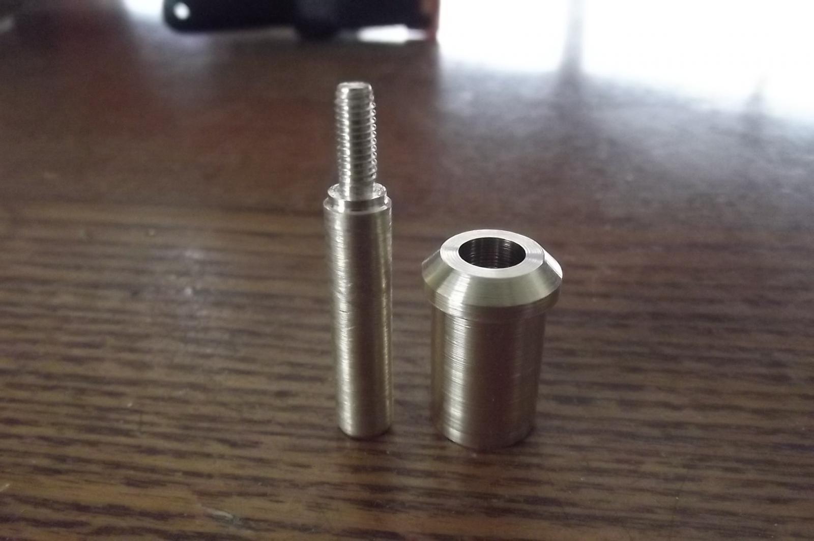
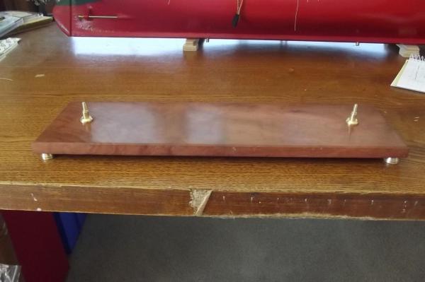
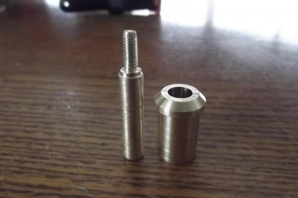
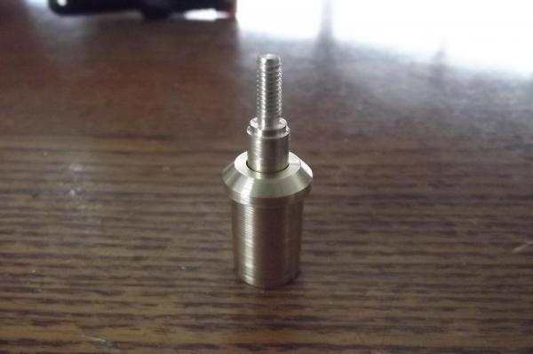
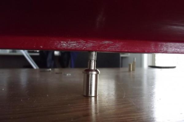
I have done a bit of machining today, I needed to make easily removable posts to stand her on. I will use the sailing keel attachment posts as the stand posts by screwing extension posts into them which will then locate into brass bosses in the display stand. I think this should make the change between sailing and displaying pretty easy. The boss will be epoxied into the display base and the post will just slide into it.
-
I've been doing some machining today too but NOTHING compared to what you are doing !!
-
Ah yes! that makes sense. Are you going to do the whole reversing mechanism?
-
As some will know I do enjoy a mechanical challenge so this build is really getting interesting now.
-
Clever design Michael, as one would expect. Why the extra sump area outside the crank case?
-
I suppose when you put it that way I probably could have bought a RTR tug and had it moored at the bank ready to go, It would have cost more than the auxiliary power in the schooner. Much less headaches though! Still, what I have is in keeping with my goal of working it all out from scratch and making it all work. I will say that if I ever build another such vessel there will be no RC reefing, been there done that, and if it has an auxiliary motor it will probably be in the ballast bulb at the bottom of the keel and powered independently.
-
Hey Dave, yes I was concerned about LiPos in the early days but as you suggested, they have come a long way especially in the charging. My charger is computerised and constantly checks and maintains cell balance. Having said that I still charge my batteries on the sink or similar metal surface. I was sticking to HiMh but everything these days is geared towards LiPo etc so I gave in. Thanks for the compliment on the sails. Floyd I know, I know but it hasn't been cheap or easy and I want to know that if something goes wrong I can drive her ashore in a hurry.