Glenn-UK
-
Posts
3,170 -
Joined
-
Last visited
Content Type
Profiles
Forums
Gallery
Events
Everything posted by Glenn-UK
-
 Many thanks, I know I could have done a better job. The template really helped and I feel confident I can make a better job for the main mast stay snaking.
- 587 replies
-
- 2
-

-
- Indefatigable
- Vanguard Models
- (and 1 more)
-
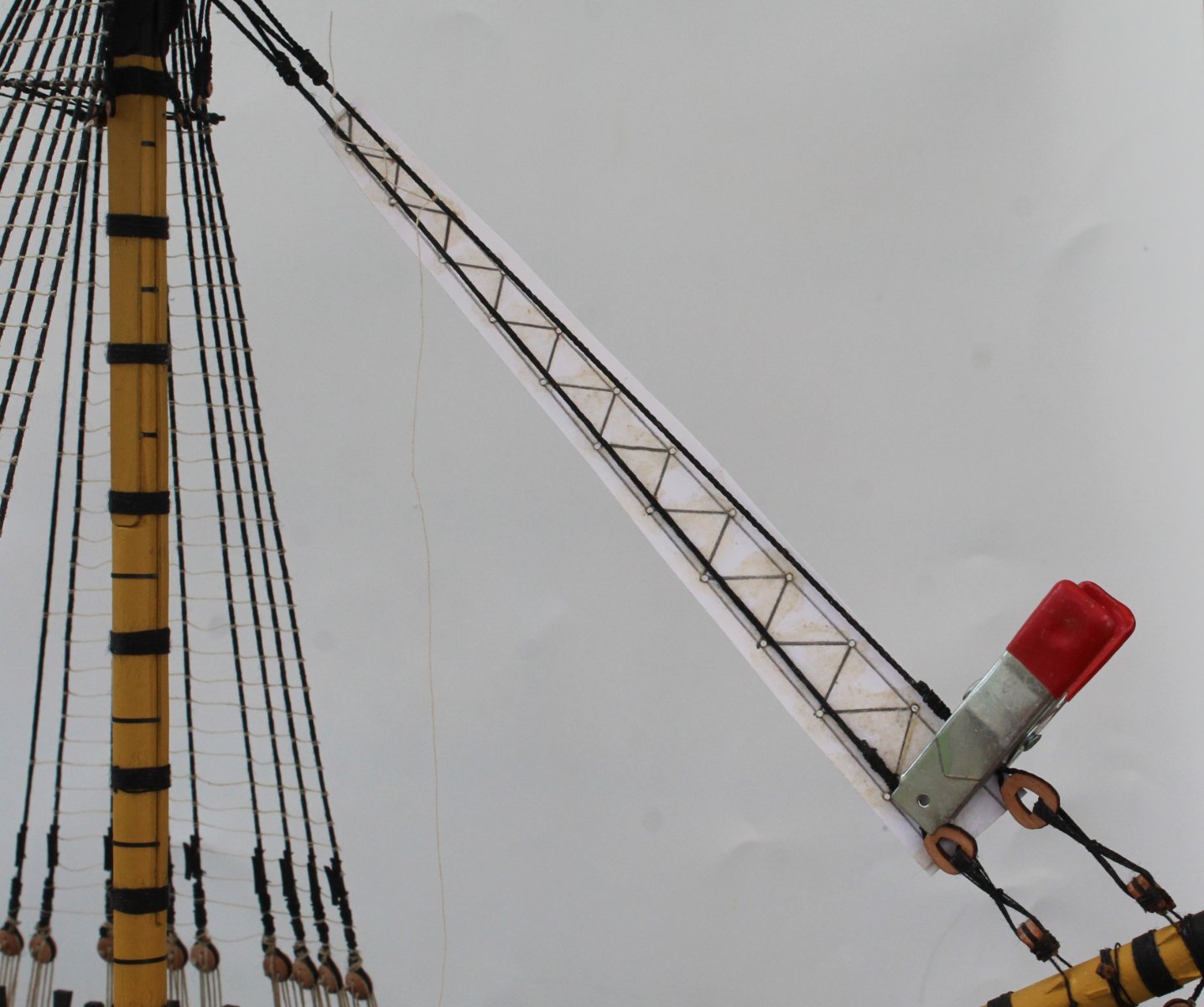
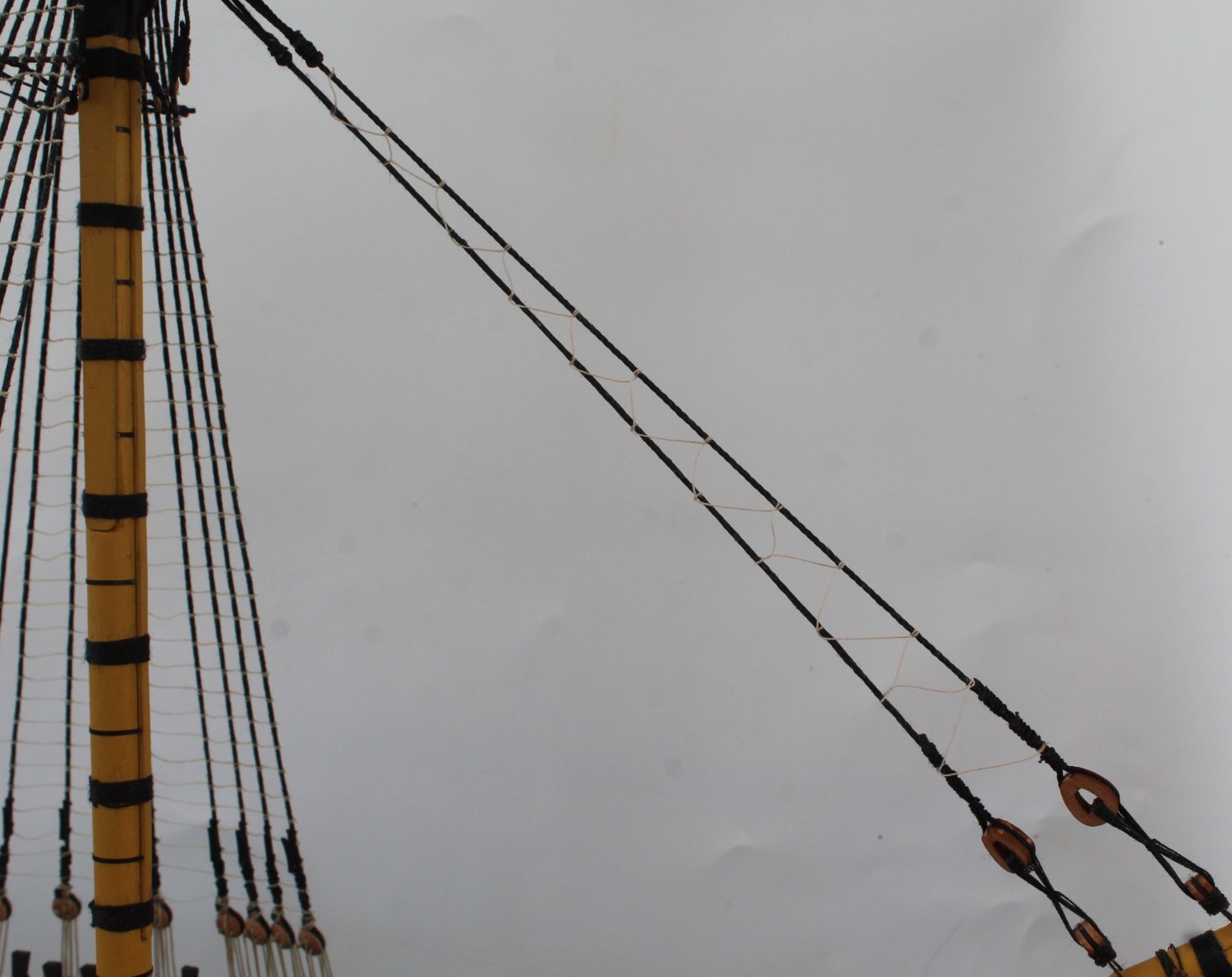
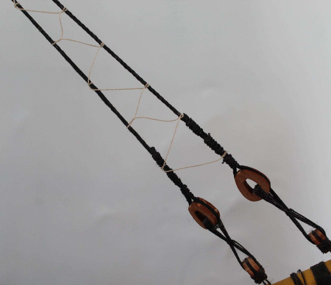
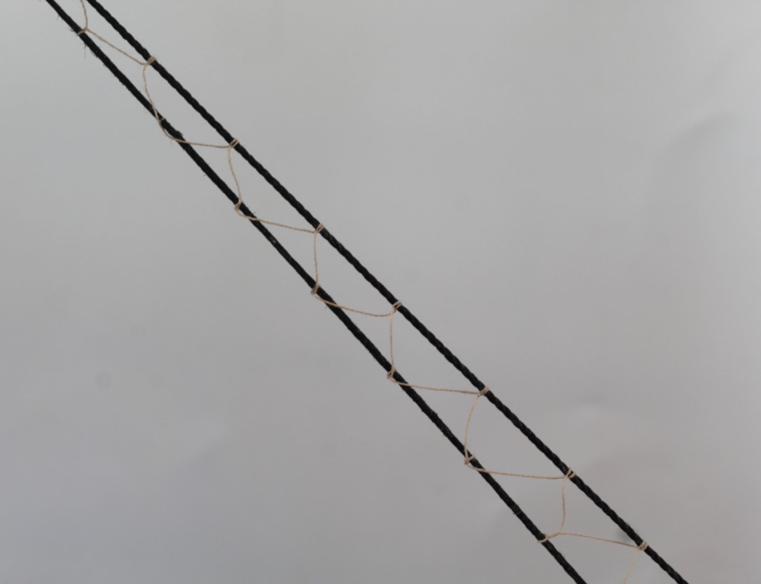
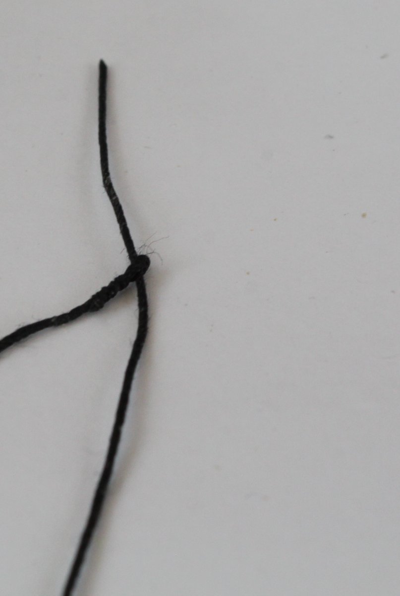
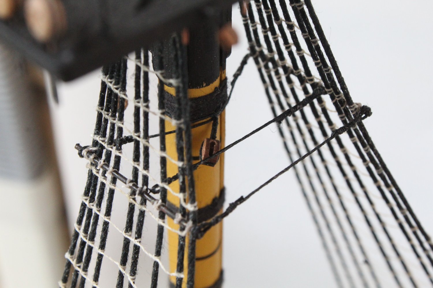
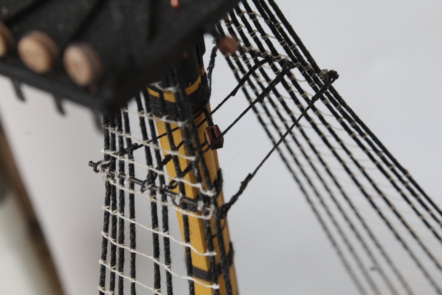
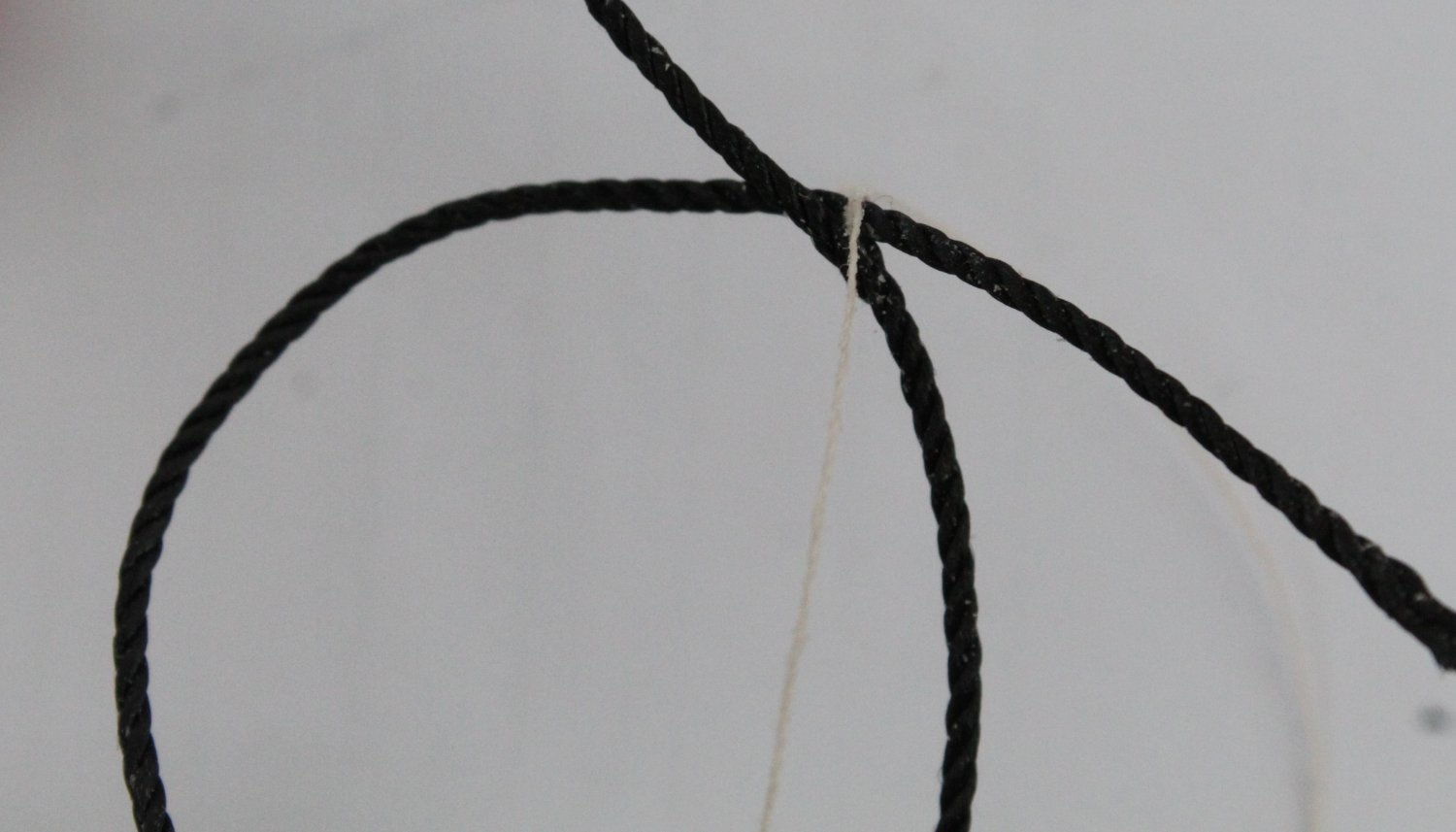
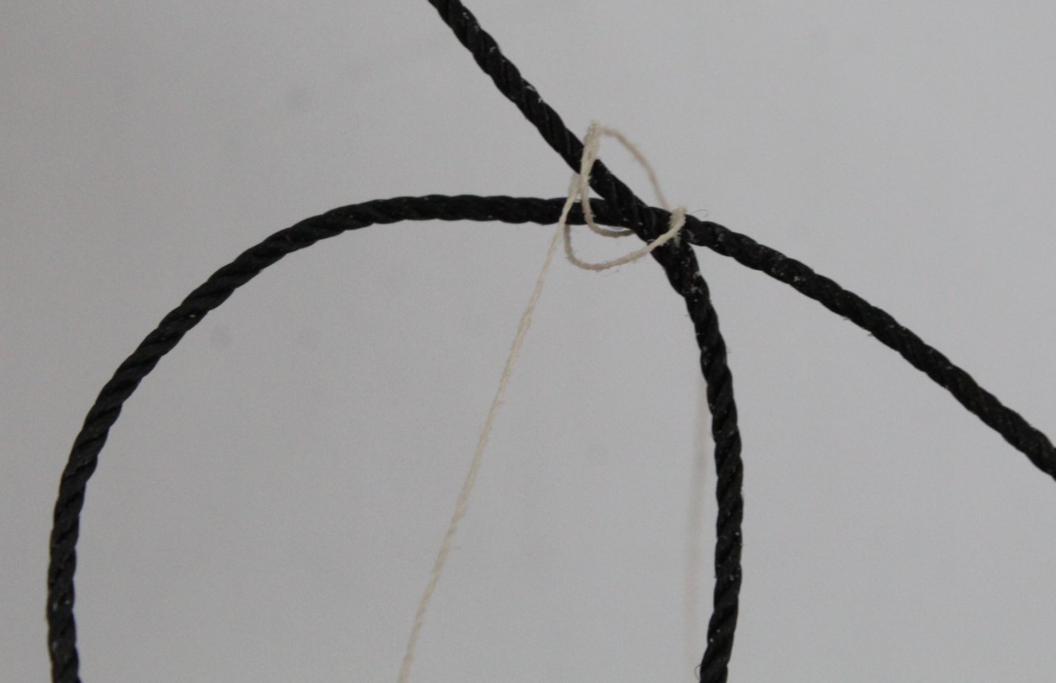
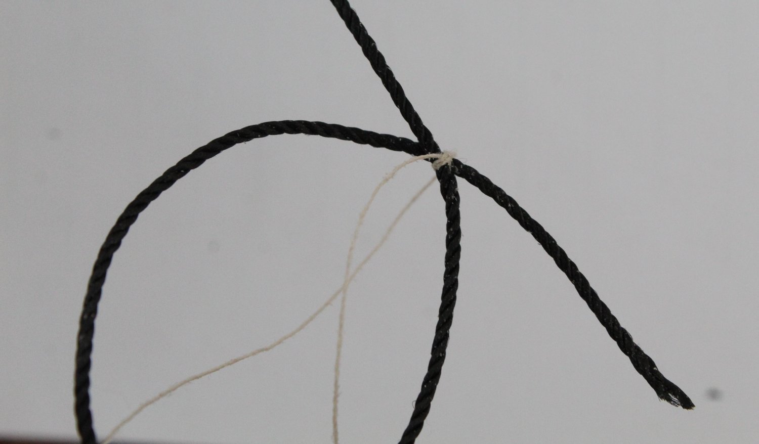
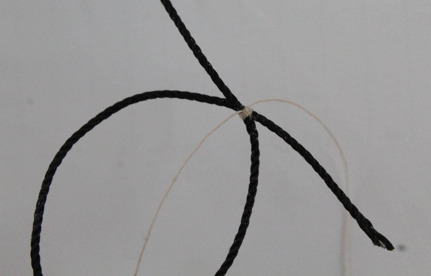
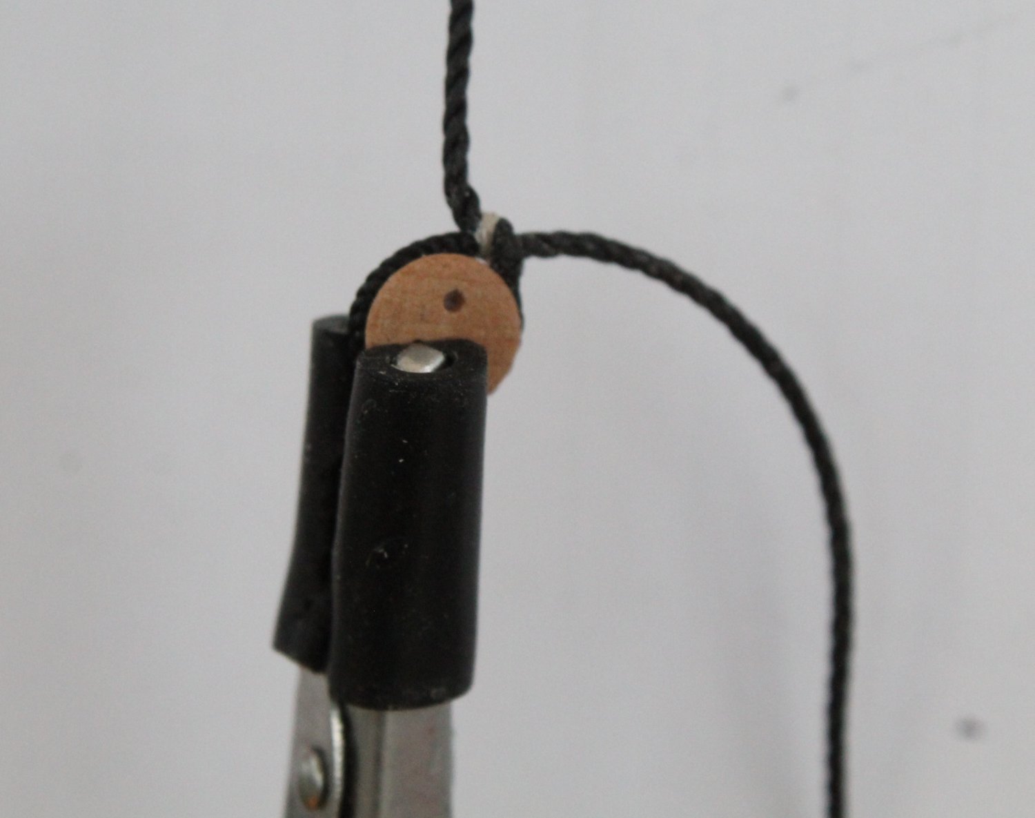
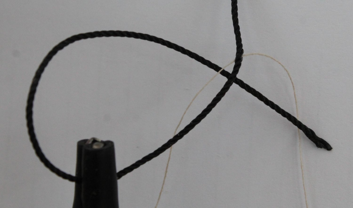
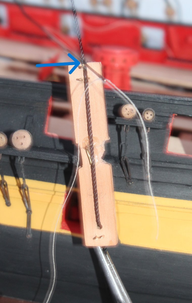
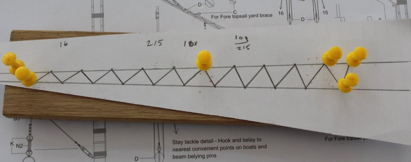
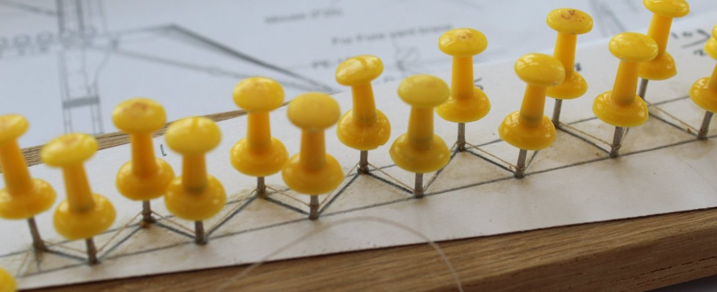
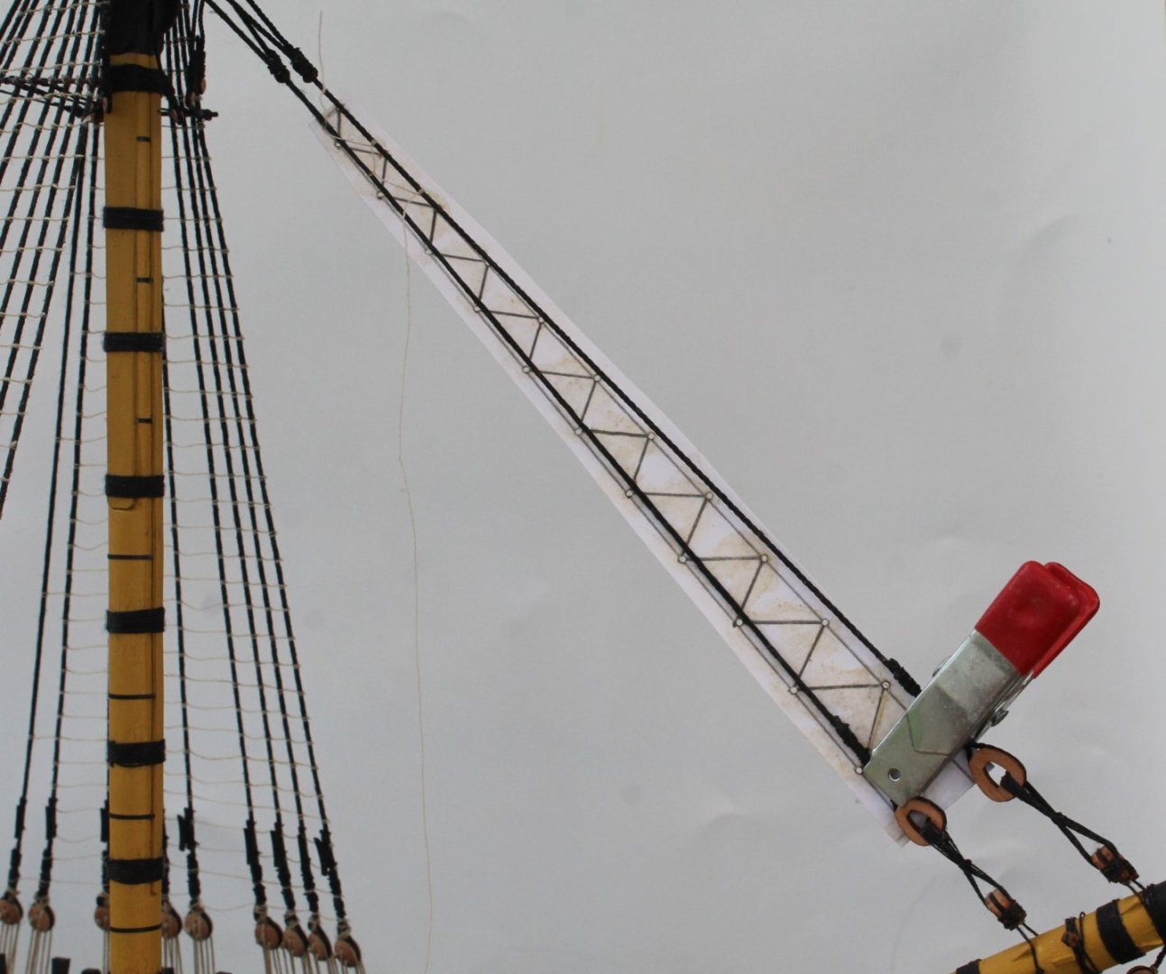
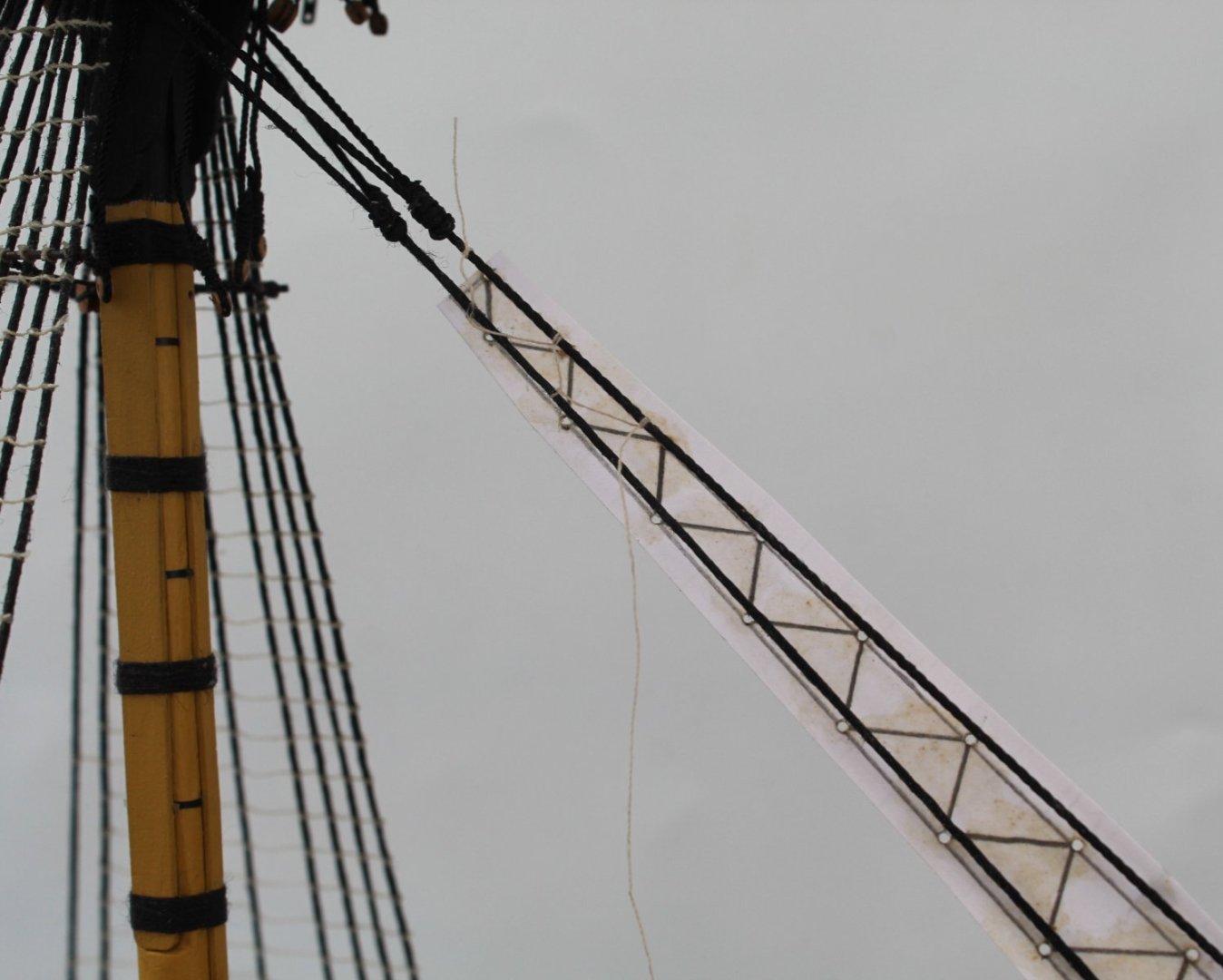
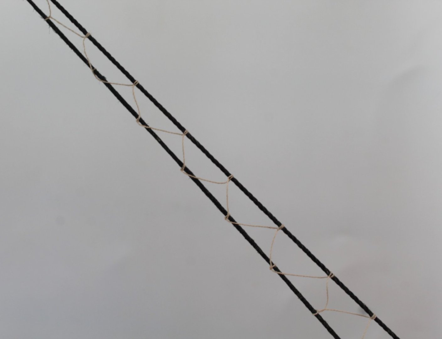
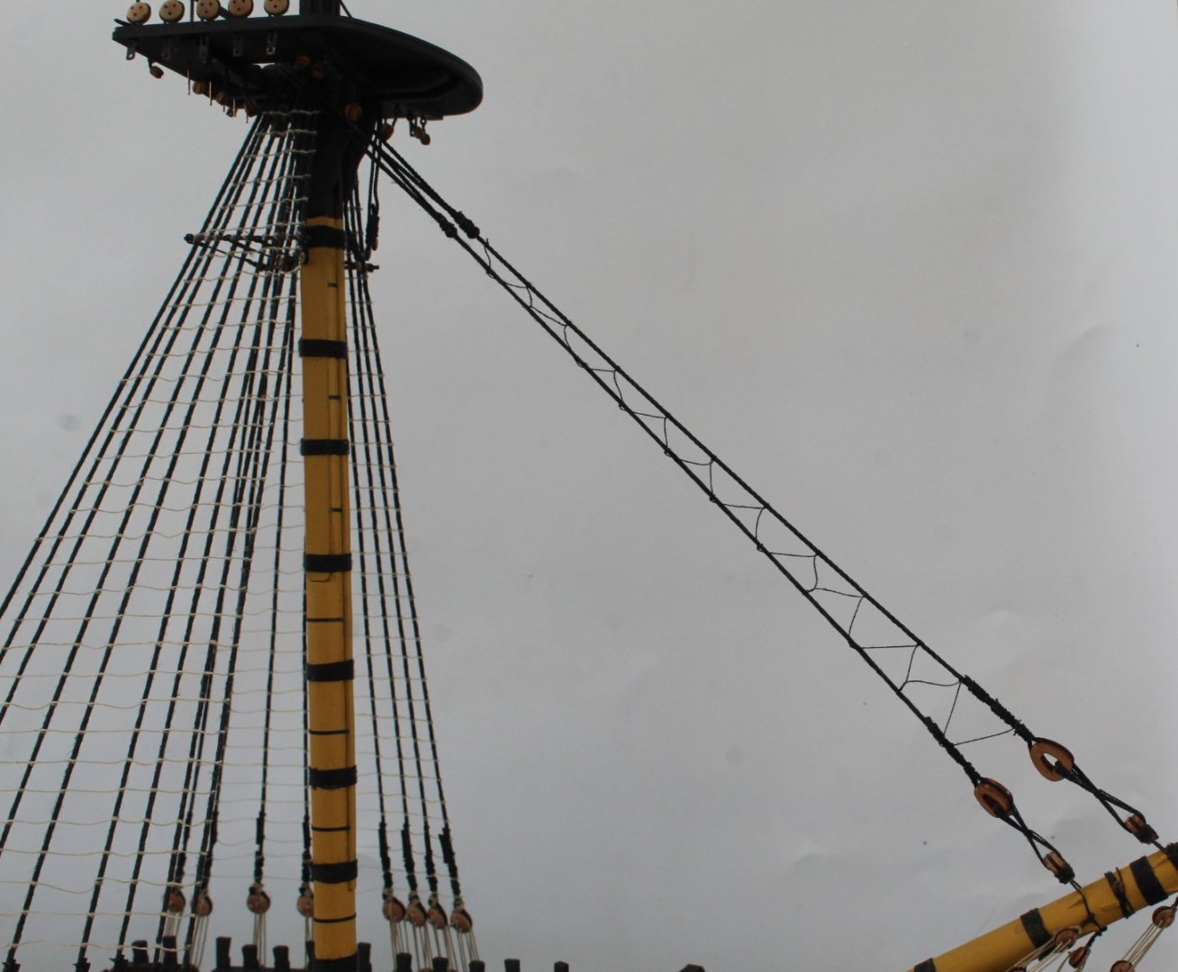
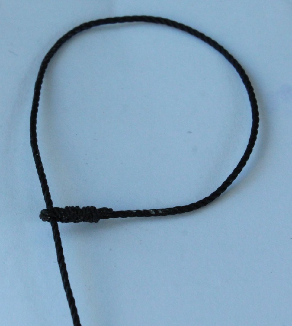
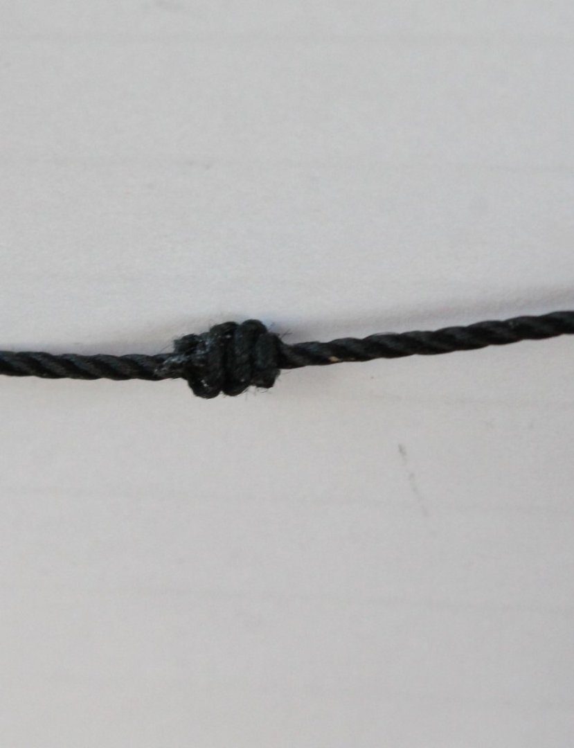
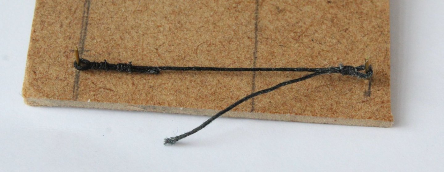
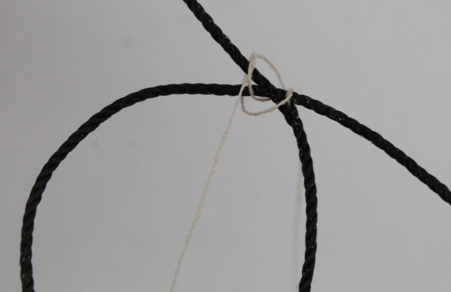
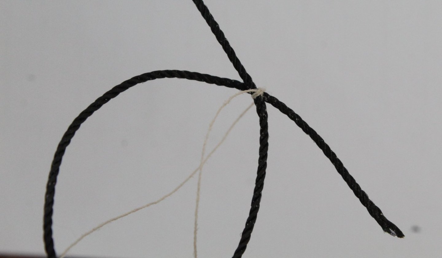
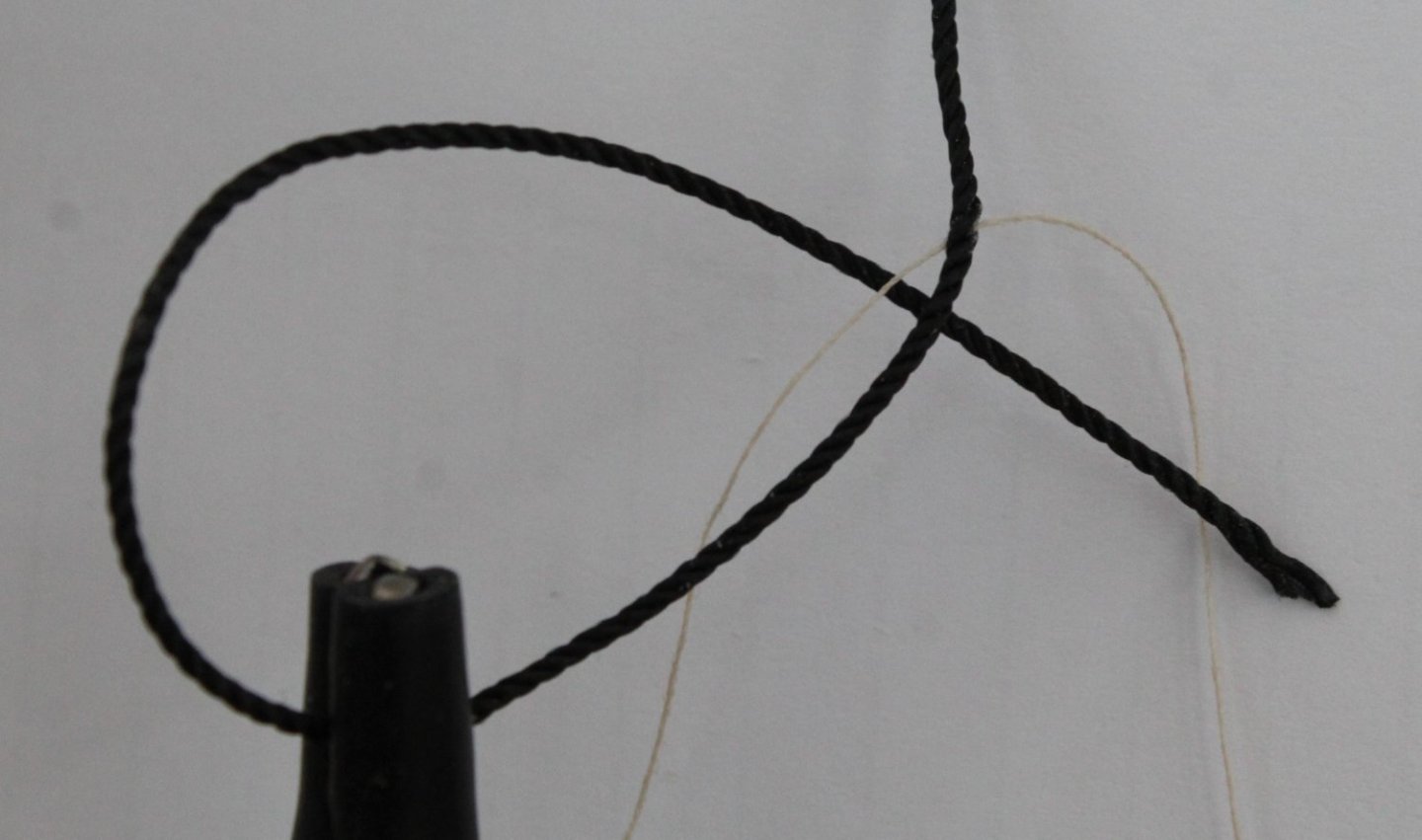
Adding The Snaking This is this first time I have added snaking to one of my models. I tried a few different methods to add between the fore stay and preventor but I really struggled to get them looking anywhere near passable. This morning I thought I had thought of a fool proof method, which was based on what I use to do when building Airfix models boats as a young boy. The method was essentially to pre-make the snaking and then to attach to the stay and preventor. I started this process by making a template. I added a series of pins where the snaking connects to the stay and preventor. A length of thread was then wrapped around these pins. A coat of diluted pva was applied to the thread. and left to dry. I was hoping that, once the thread had dried out, the thread would retain the required shape and that I could then tie it to the stay and preventor. I made a schoolboy error in that, as the diluted glue dried the thread had become stuck, in some places to the template. I lost the shape as I tried to release the thread from the template. Although I thought the method was a viable option I decided to abandon this approach. All was not lost. I retained the template and clamped it to the stay and preventor. It was then a case of securing the thread to the stay and preventor. I ended up using a clove hitch to secure the thread to the preventor (top). I used a simple wrap around for the stay (bottom). I did not make a great job of the snaking but, compared to some of my previous efforts, I am reasonably happy with the end result. The final task was to apply some Indian ink to dye the snaking. The snaking is not perfect but I do not have the patience or will power to rip it off (again) to get a better end result.


- 587 replies
-
- 14
-
-
- Indefatigable
- Vanguard Models
- (and 1 more)
-
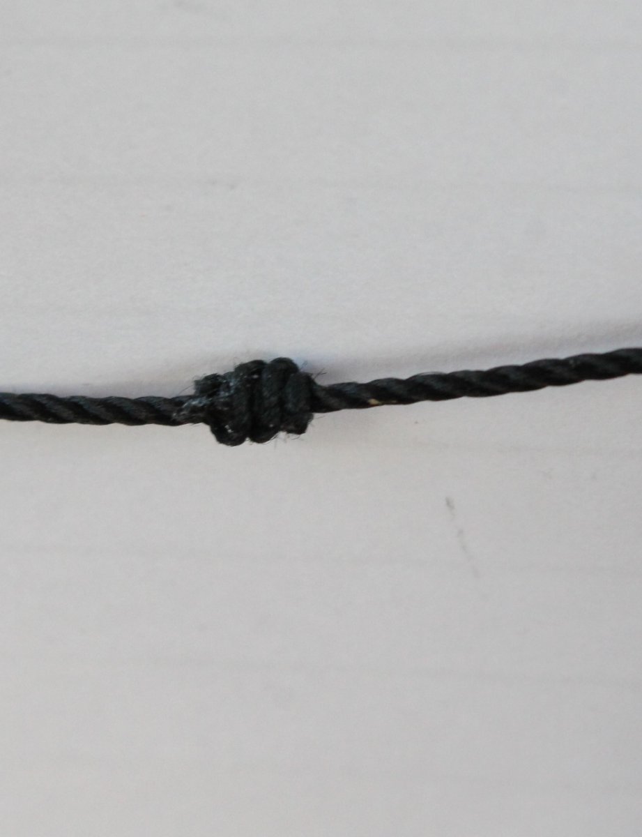
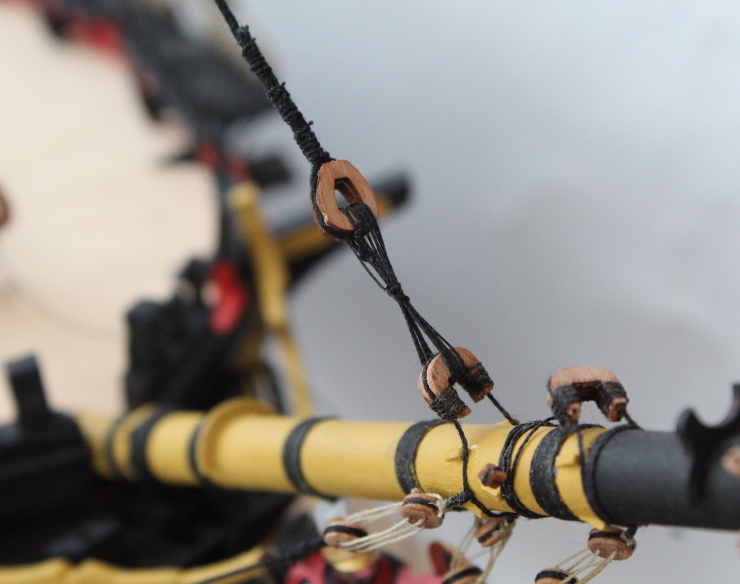
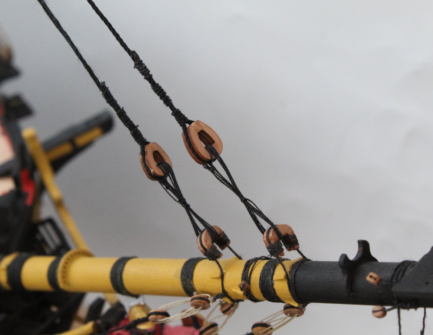
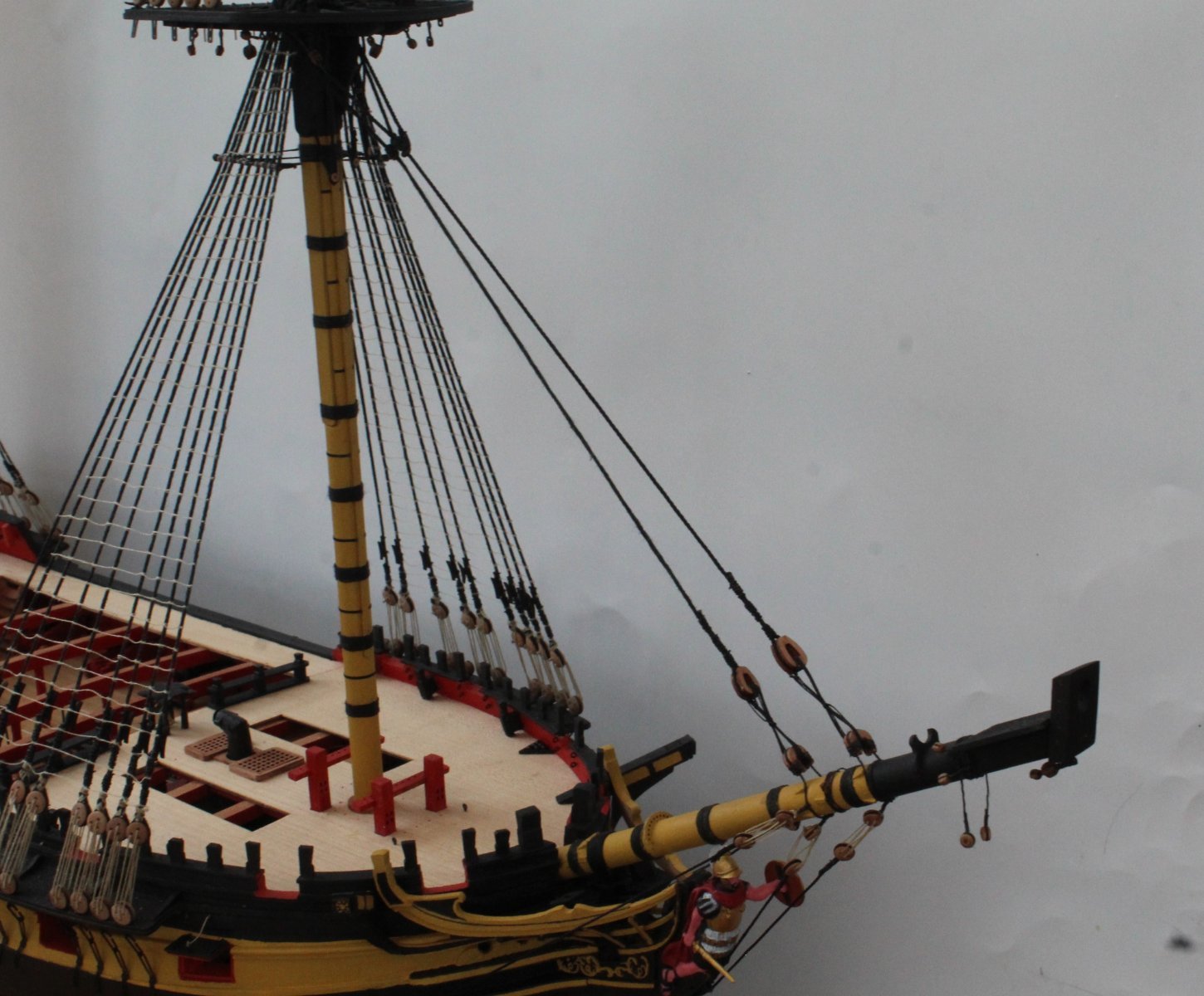
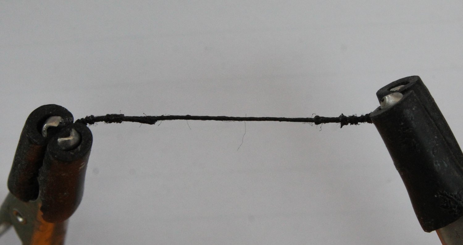
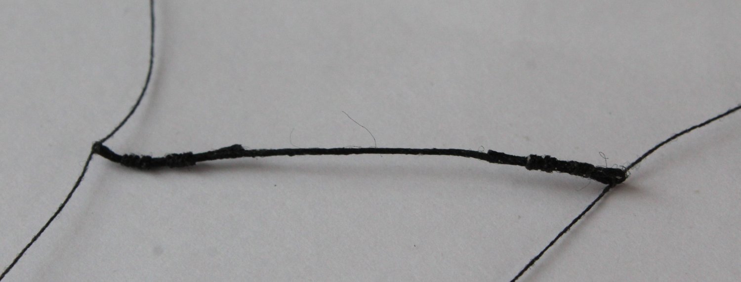
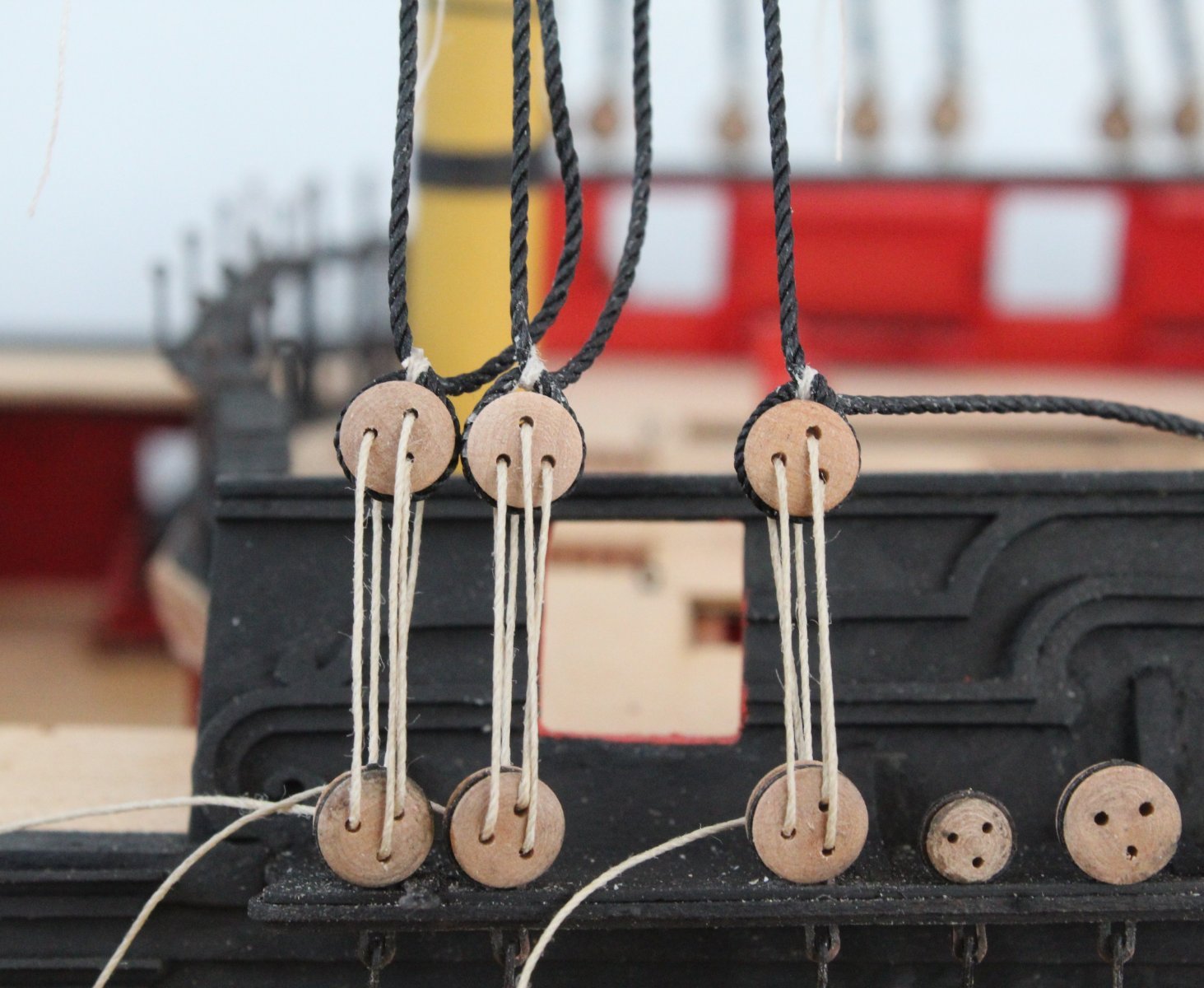
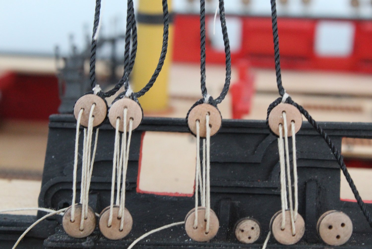
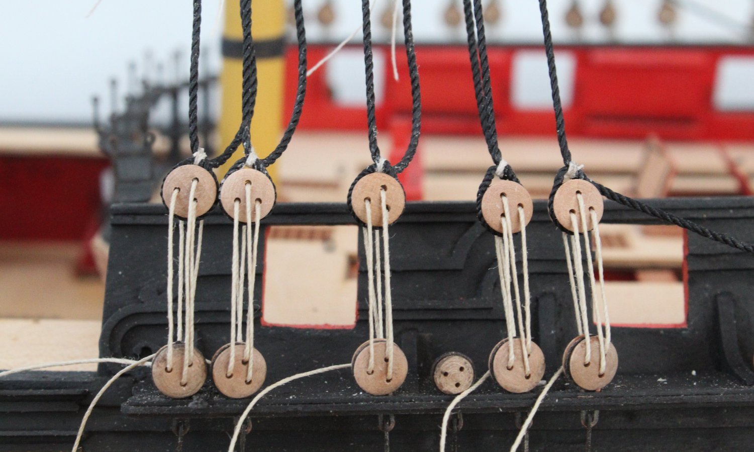
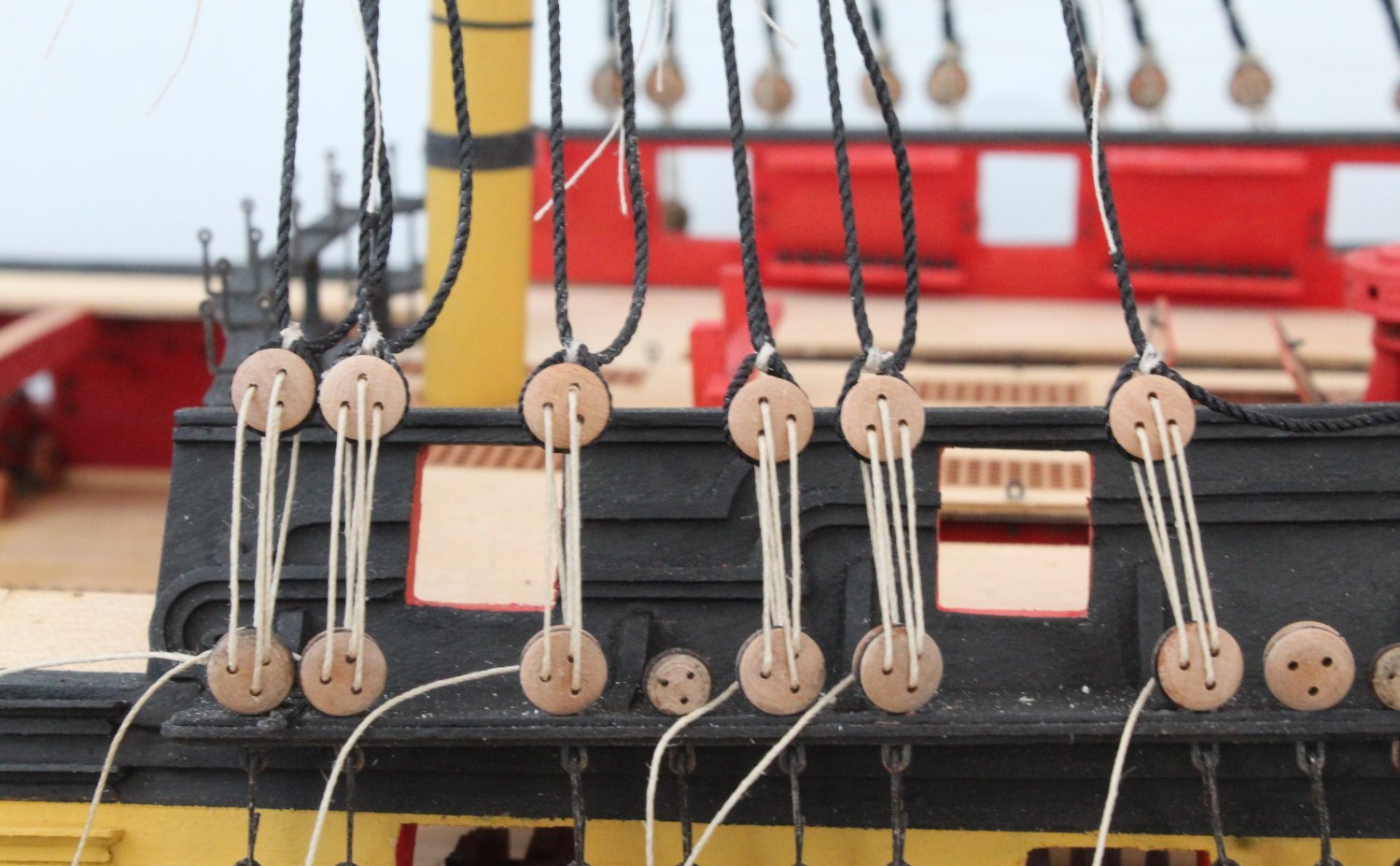
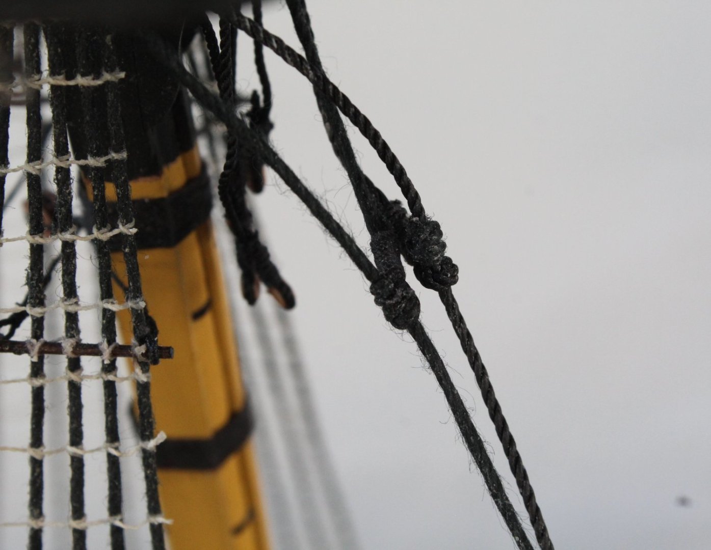
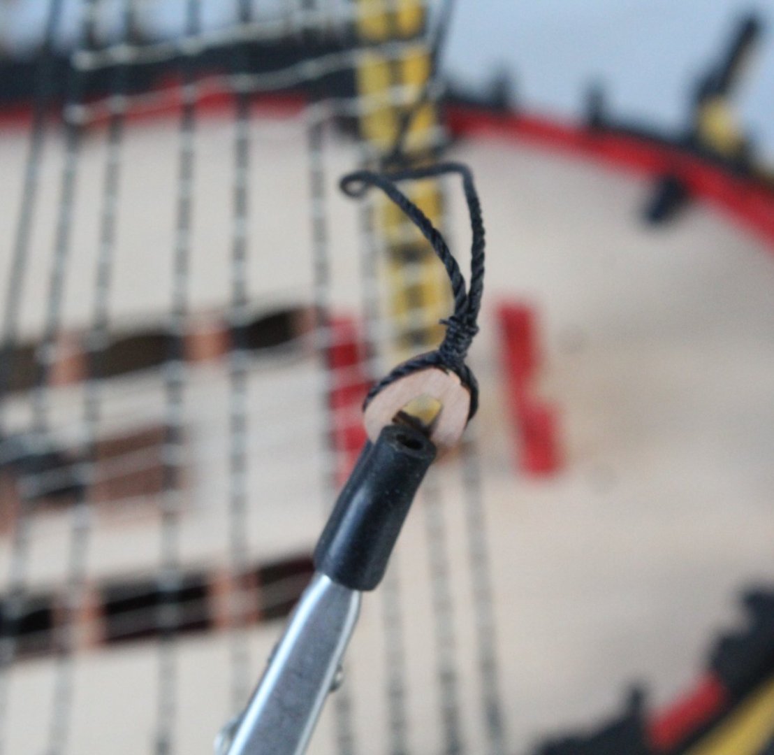
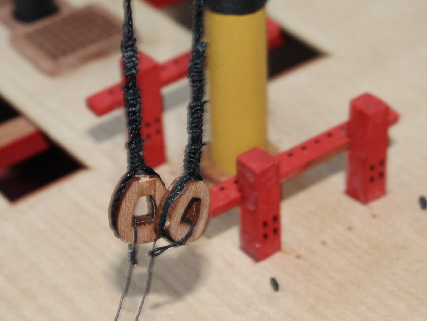
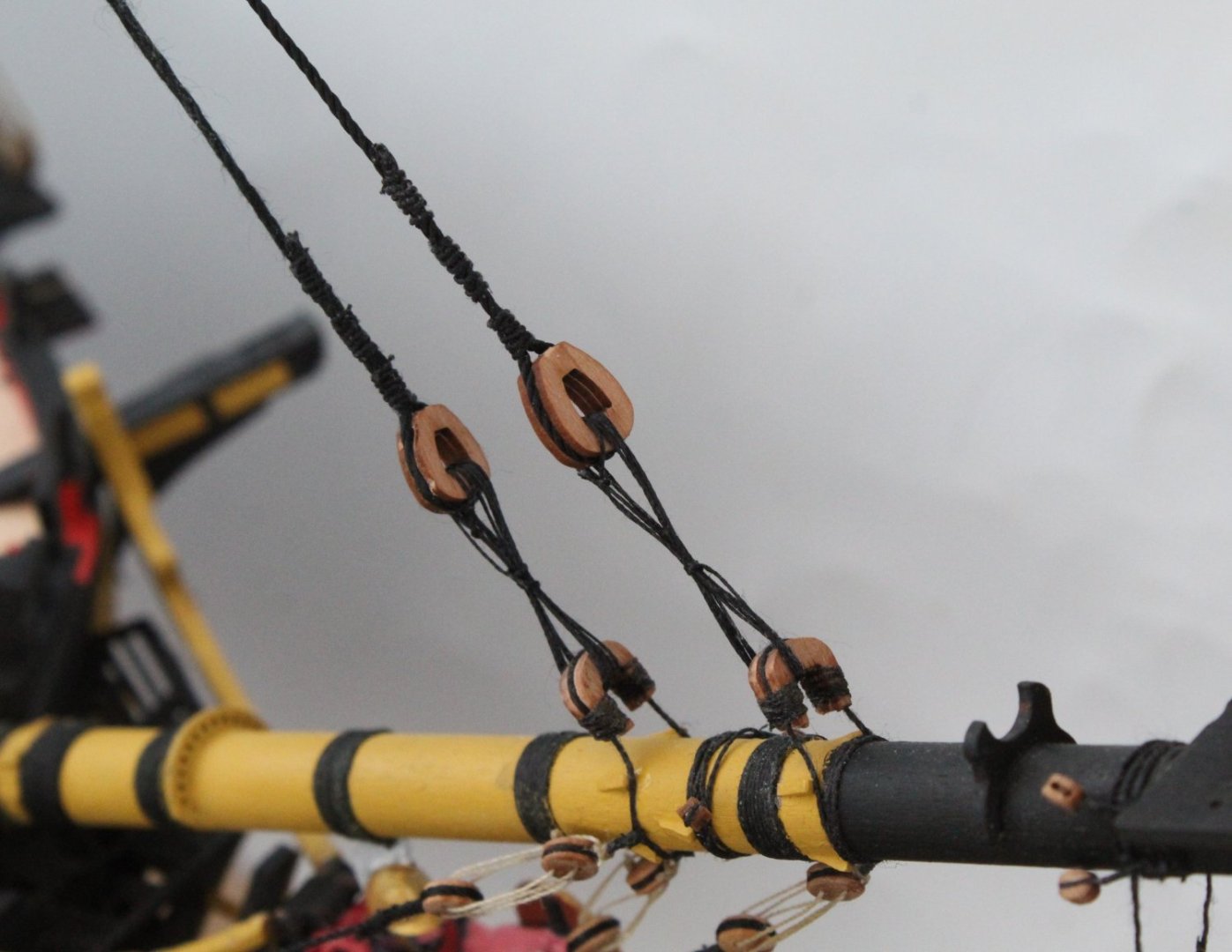
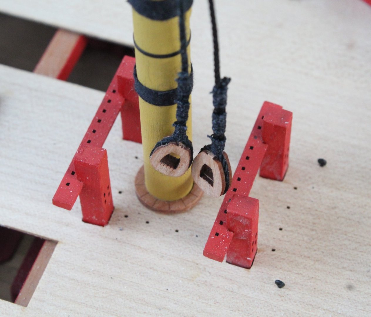
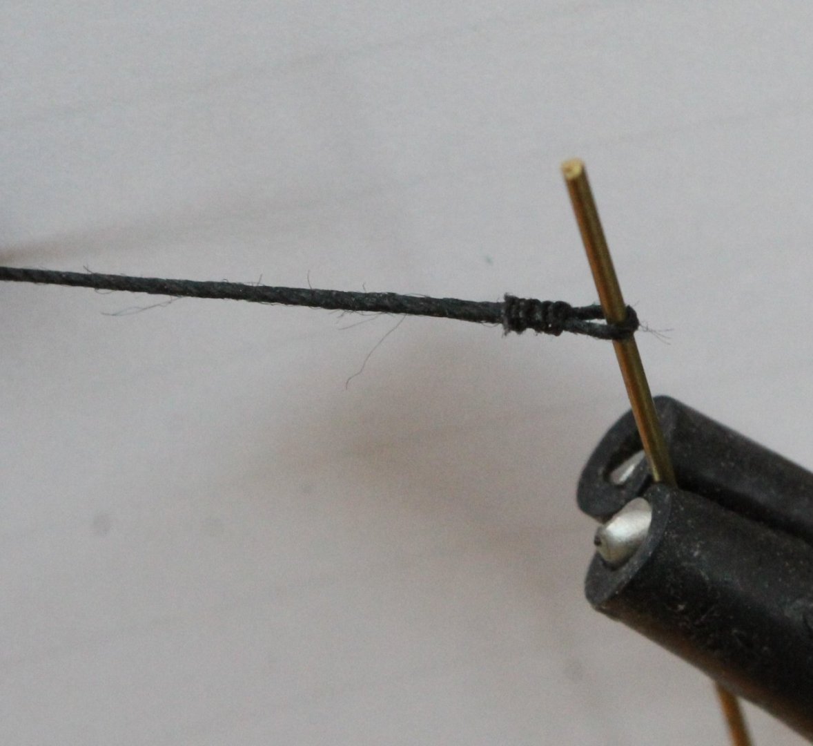
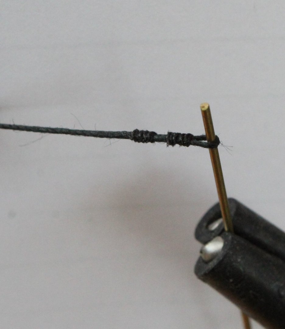
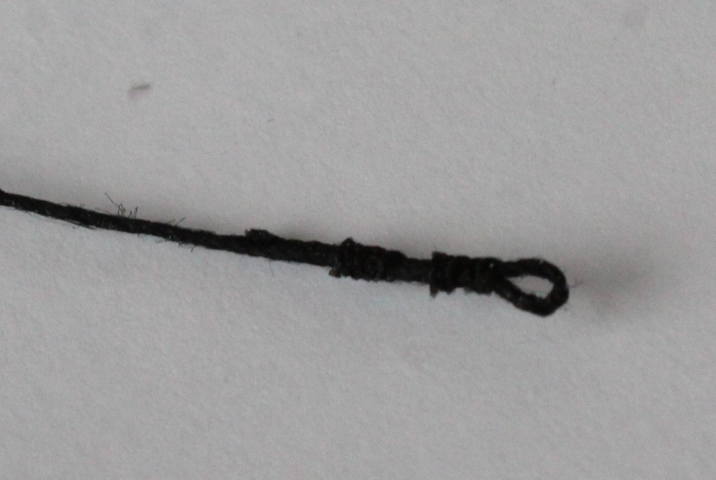
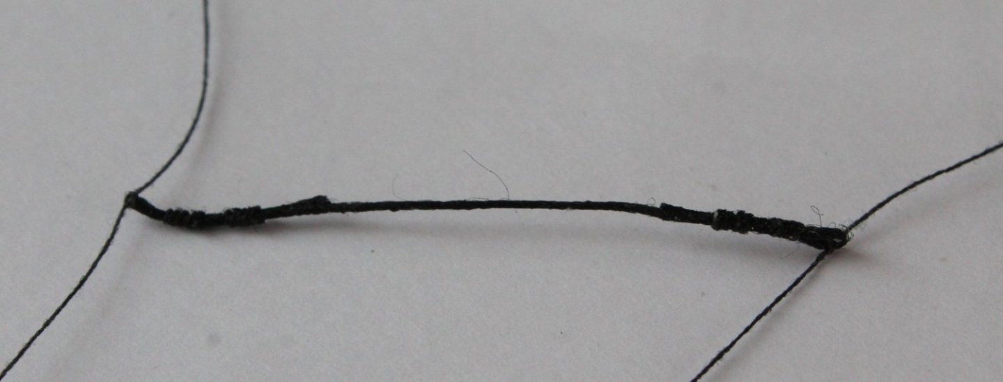
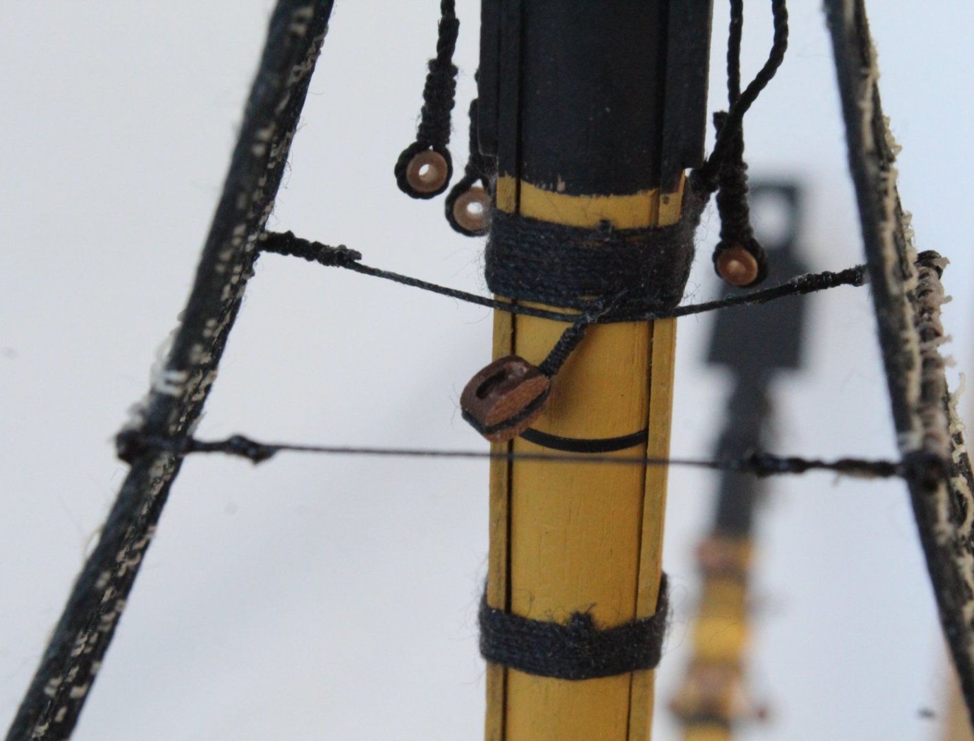
Foremast Stay and Preventor I have now added the foremast stay and foremast preventor and I have detailed the method I used to complete this task. I started off with making a thimble in one end of the stay and preventor threads. I made sure the thread would pass through the thimble. Next I added a mouse to each thread. This was a two part process. I used some 0.1mm black thread for the central section and then added some 0.25mm black thread before, over and after the 0.1mm black thread. The mouse does slide up and down the thread. The stay and preventor were then wrapped around the foremast and the free ends passed though their respective thimbles. The position of each mouse was then adjusted and a touch a ca glue was used to prevent further movement of the mouse. The close heart was then positioned in the stay (and preventor). I used my quad hands for this, certainly one of the best and essential tools used for my model making when adding the rigging. I have started to add the seizing in the next photo. I ended up added three seizing's to the stay and preventor. I created a thimble to one end of each of the lanyards and then added them to the closed hearts. It was then a simple case of adding a few loops. The completed stay and preventor, ready and waiting for the snaking to be added. I am currently experimenting with different methods for adding the snaking as my first two attempts did not passed muster, fingers crossed it will be third time lucky.


- 587 replies
-
- 10
-
-

-
- Indefatigable
- Vanguard Models
- (and 1 more)
-
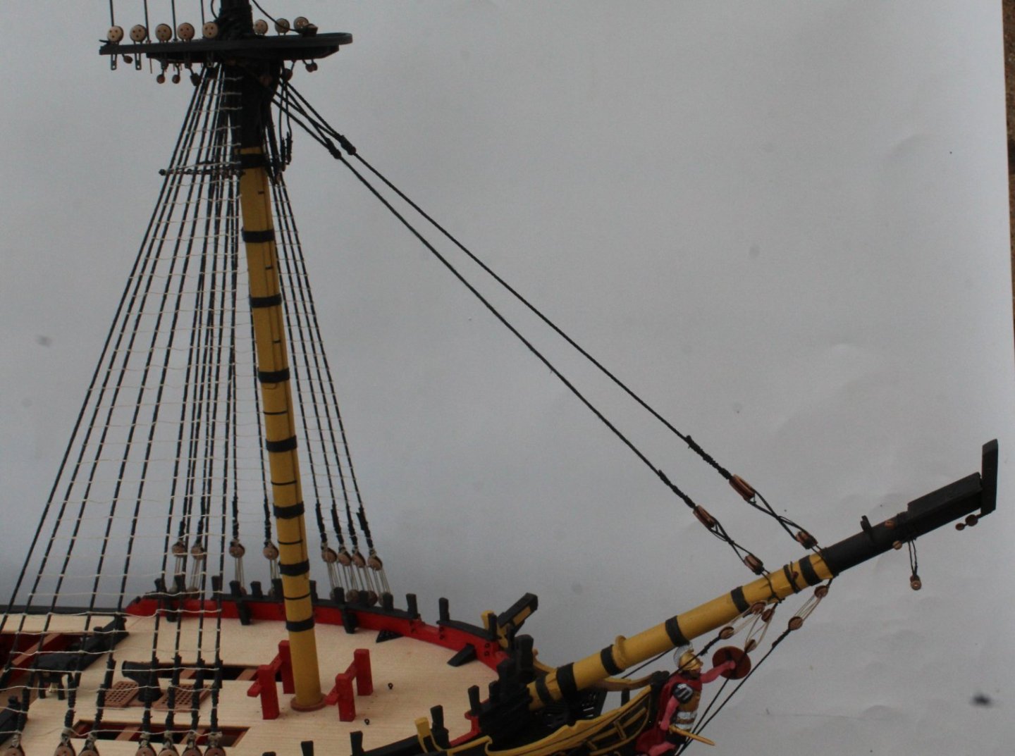
On the Indy the fore stay and preventor are not looped around the bowsprit and spritsail as shown in Petersonn's book. They are actually located nearer the bow and are only looped around the bowsprit. The bowsprit shroud deadeyes are also fitted to these loops.
- 587 replies
-
- 3
-
-
- Indefatigable
- Vanguard Models
- (and 1 more)
-
Thanks for the info and kind comments. I generally follow the rigging plans provided with the kit. I also refer to Longridge and Petersson's books to help to get a better understanding. The forestay and forestay preventor stays are open heart type fixed to the bowsprit (Type D in your photo) and closed heart types fitted to the actual stays as shown in the photo below.
- 587 replies
-
- 3
-
-
- Indefatigable
- Vanguard Models
- (and 1 more)
-
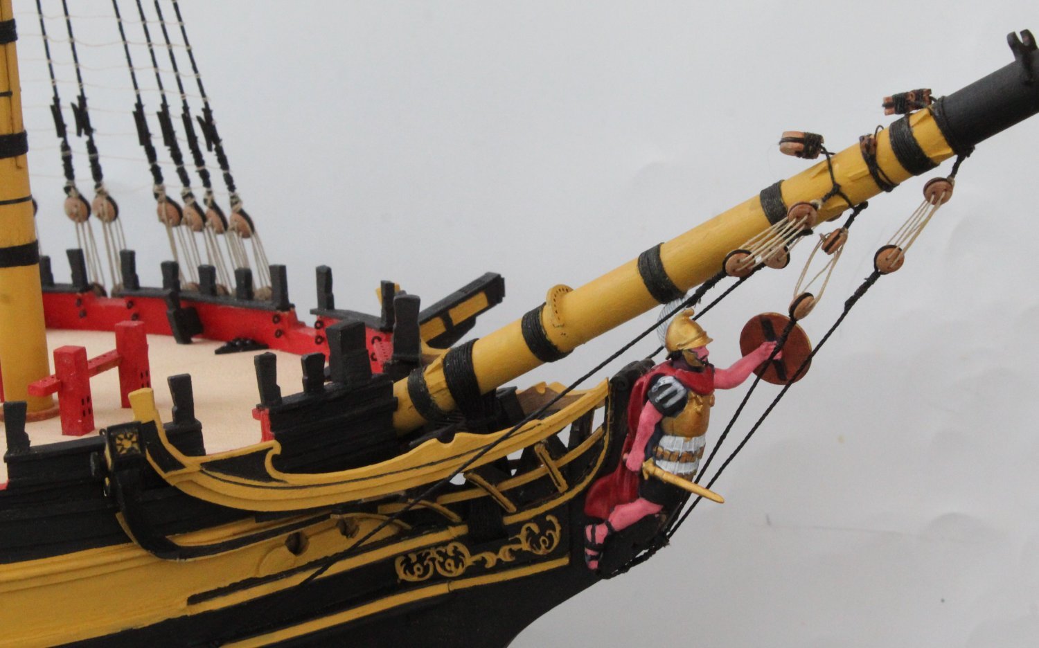
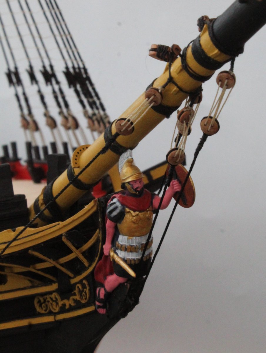
Bowsprit Shrouds I have managed to reattached the broken sword to the figurehead. I also reattached the rails. It was then a case of adding the 4 shrouds for the bowsprit. The rigging of the shrouds was relatively easy to do. Next up will be to add the foremast stay and preventer.


- 587 replies
-
- 13
-
-
- Indefatigable
- Vanguard Models
- (and 1 more)
-
It does get crowded and the model is prone to more mishaps.
- 587 replies
-
- 3
-

-
-
- Indefatigable
- Vanguard Models
- (and 1 more)
-
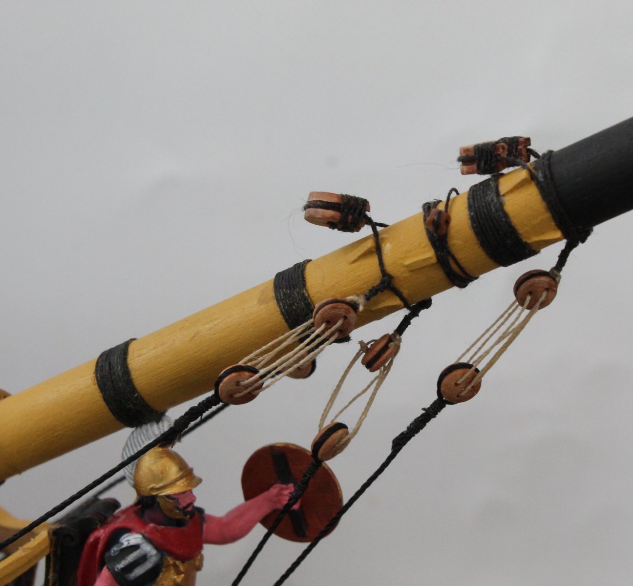
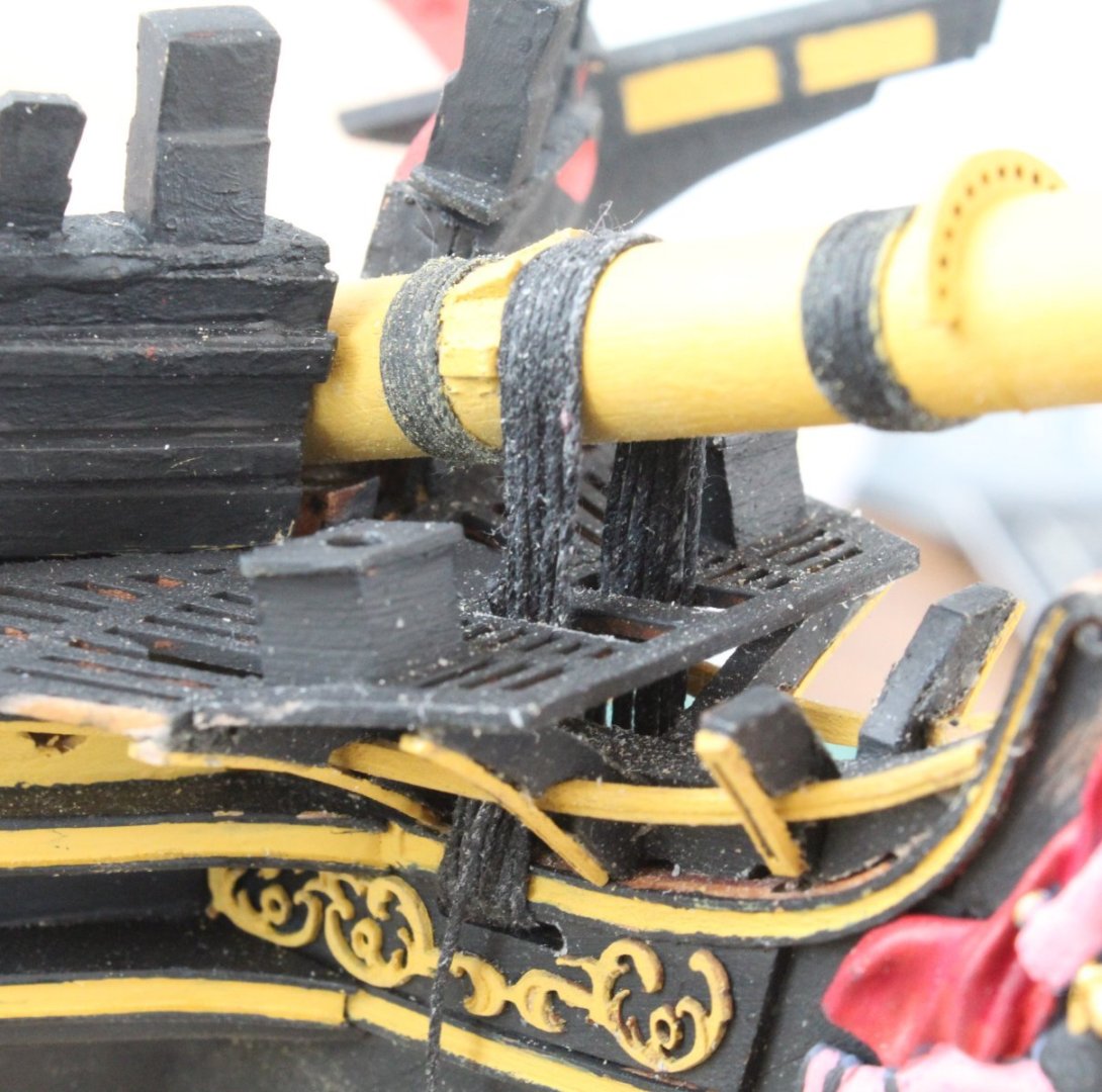
Bowsprit Gammoning Today I added the gammoning to the bowsprit. It took two attempts. On the first attempt I did not have the figurehead in place. I discovered I could not fit the figurehead once the gammoning was complete as the helmet was fouling with the wolding. Unfortunately I managed to damage the figurehead, the tip of sword broke off. I will try to reglue once the bowsprit rigging is complete, The bow rails also fell off which actually made adding the gammoning easier. I started the gammoning process by cutting a long length of 0.75mm black thread. I then passed the thread through a beeswax block a couple of times and melted it using a hairdryer. I then made a thimble at one end of the gammoning thread and checked the thread would pass through it. In the next photo I have started the gammoning rigging. The thread has been looped around the bowsprit and the free end has been fed through the thimble. In the next photo I have made 4 passes around the bowsprit. There is still some traces of beeswax on the gammoning thread but once the gammoning is complete I will use the hairdryer again to remove. The gammoning is progressing well, 8 loops have now been added in the next photo. I ended up doing 10 loops and then tied off the free end. The excess beeswax has been removed with the hairdryer.


- 587 replies
-
- 9
-
-
- Indefatigable
- Vanguard Models
- (and 1 more)
-
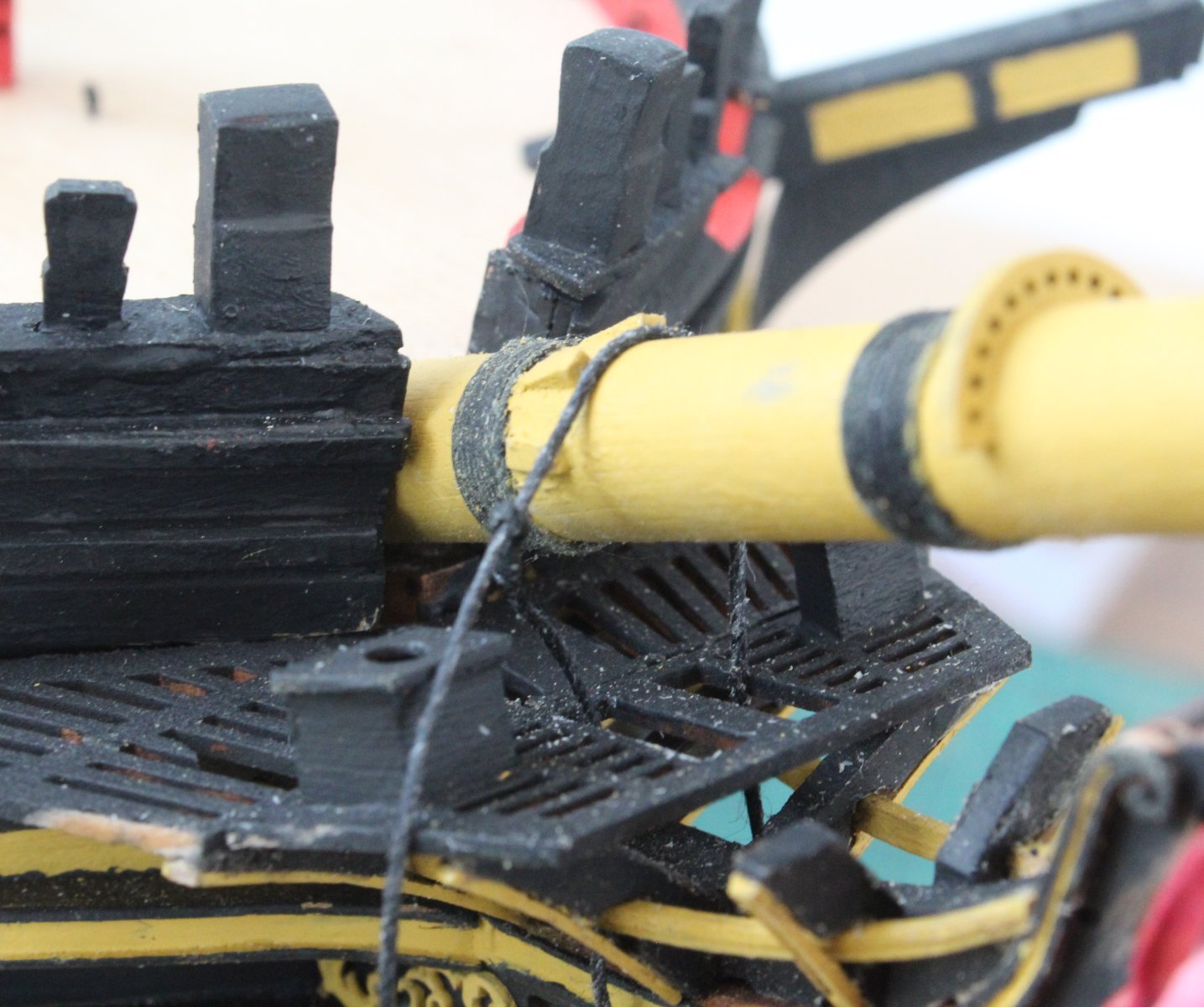
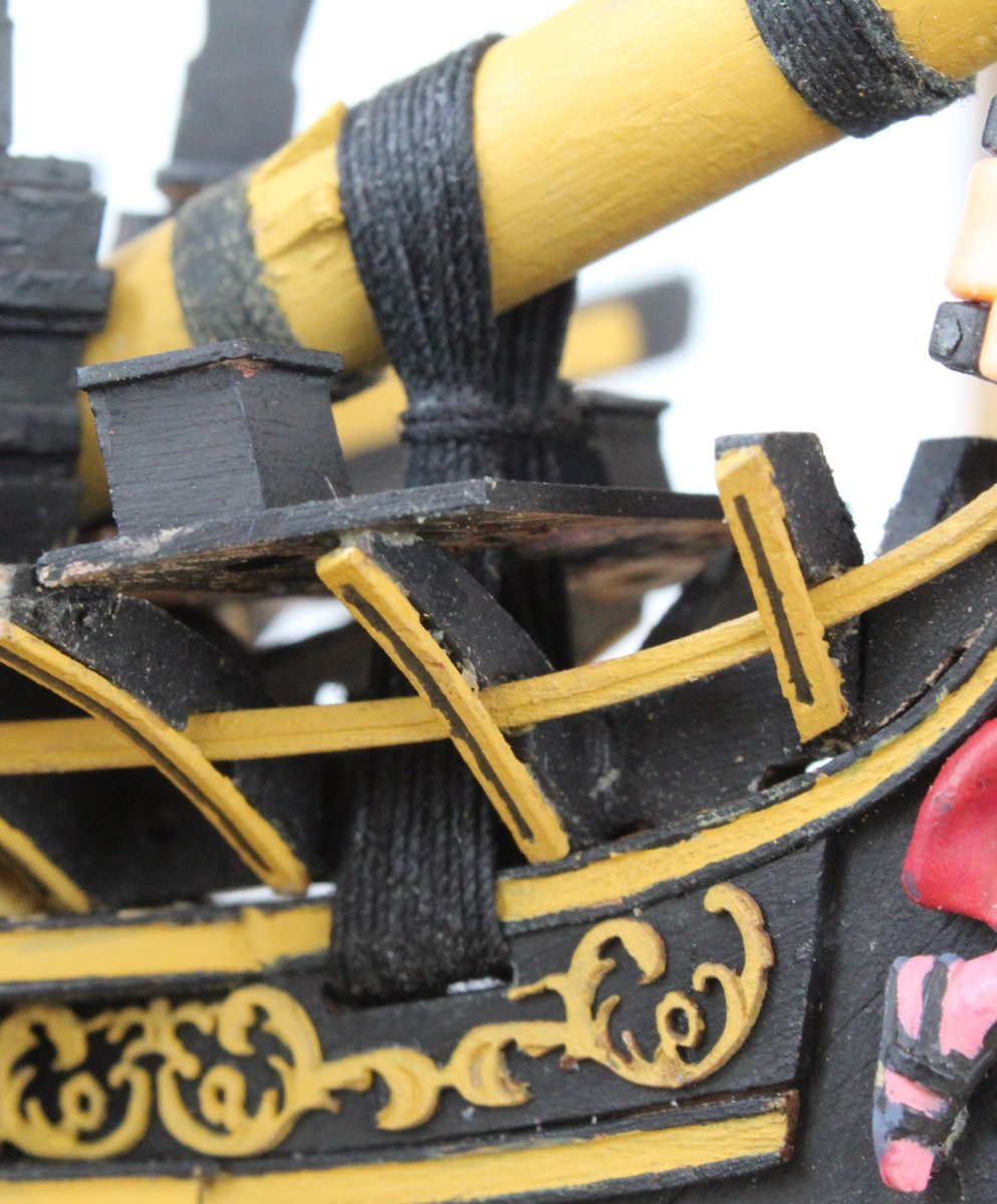
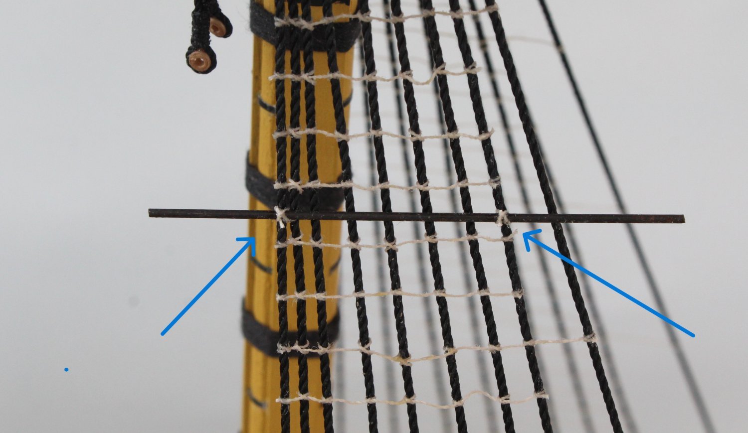
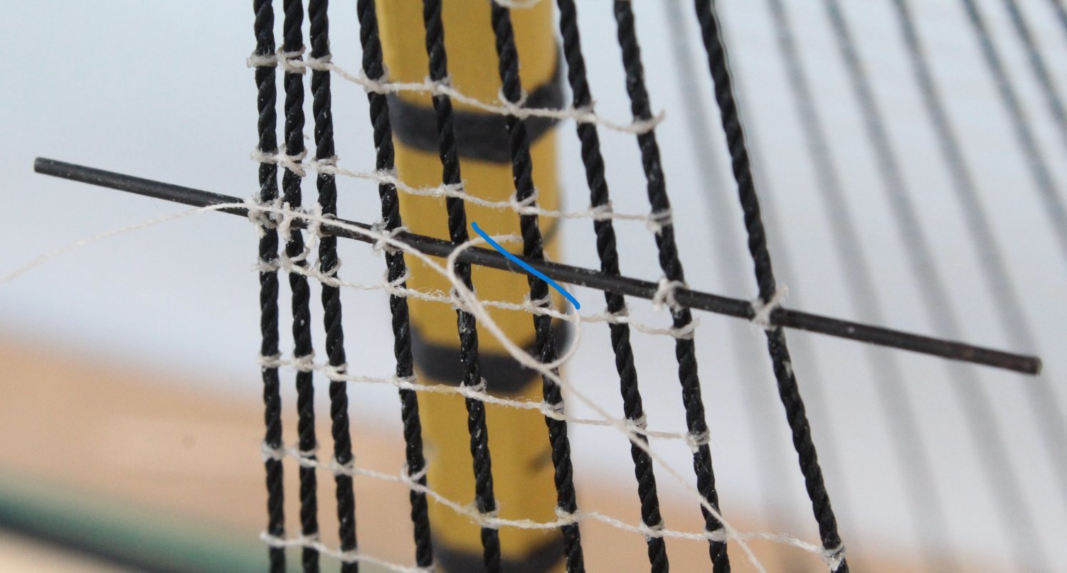
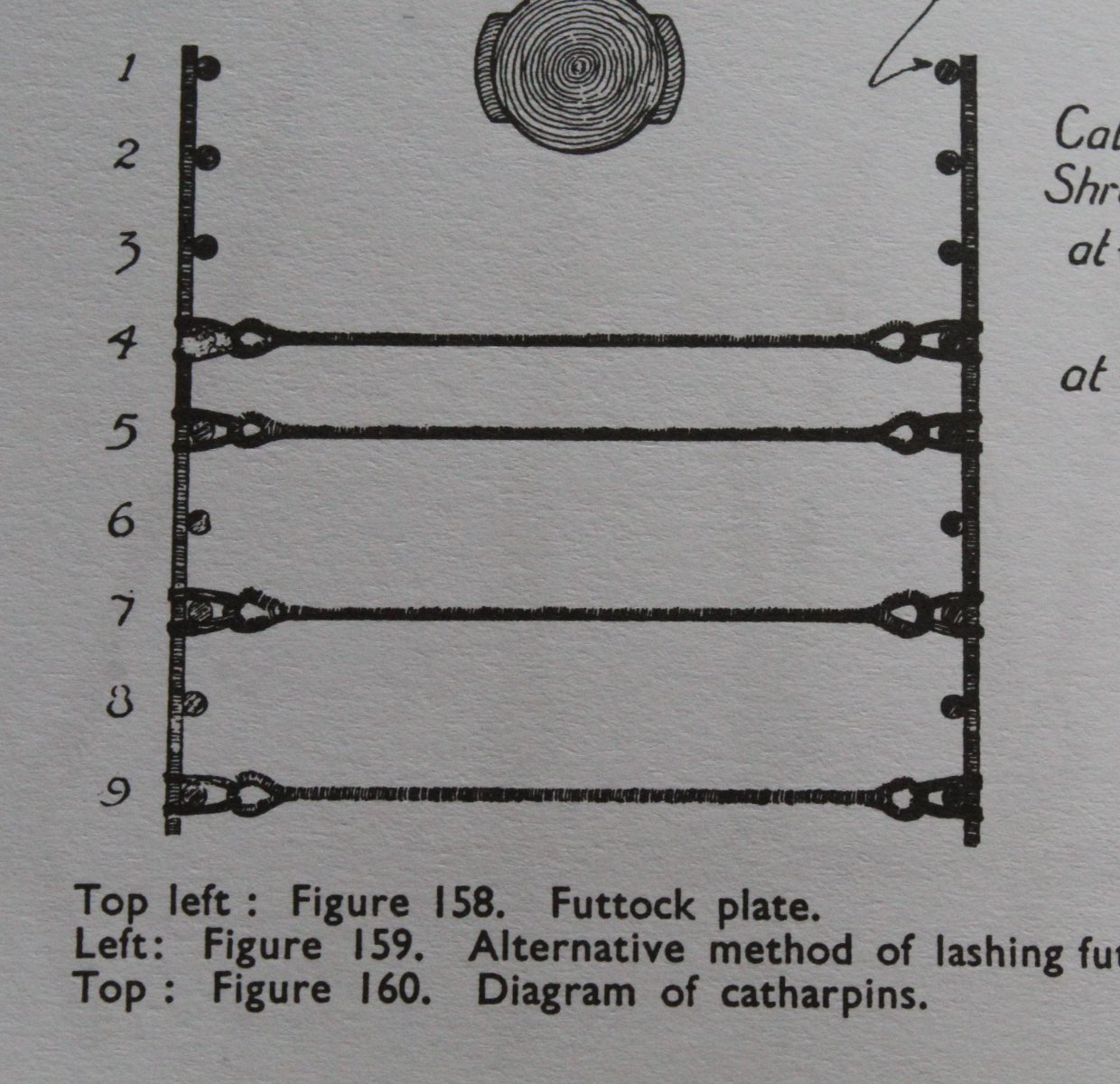
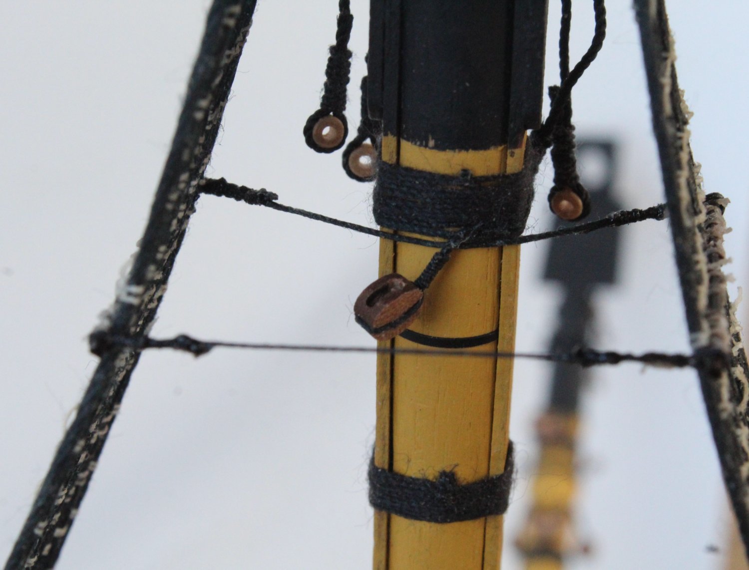
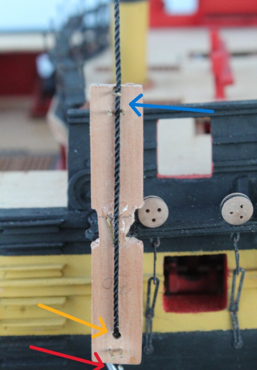
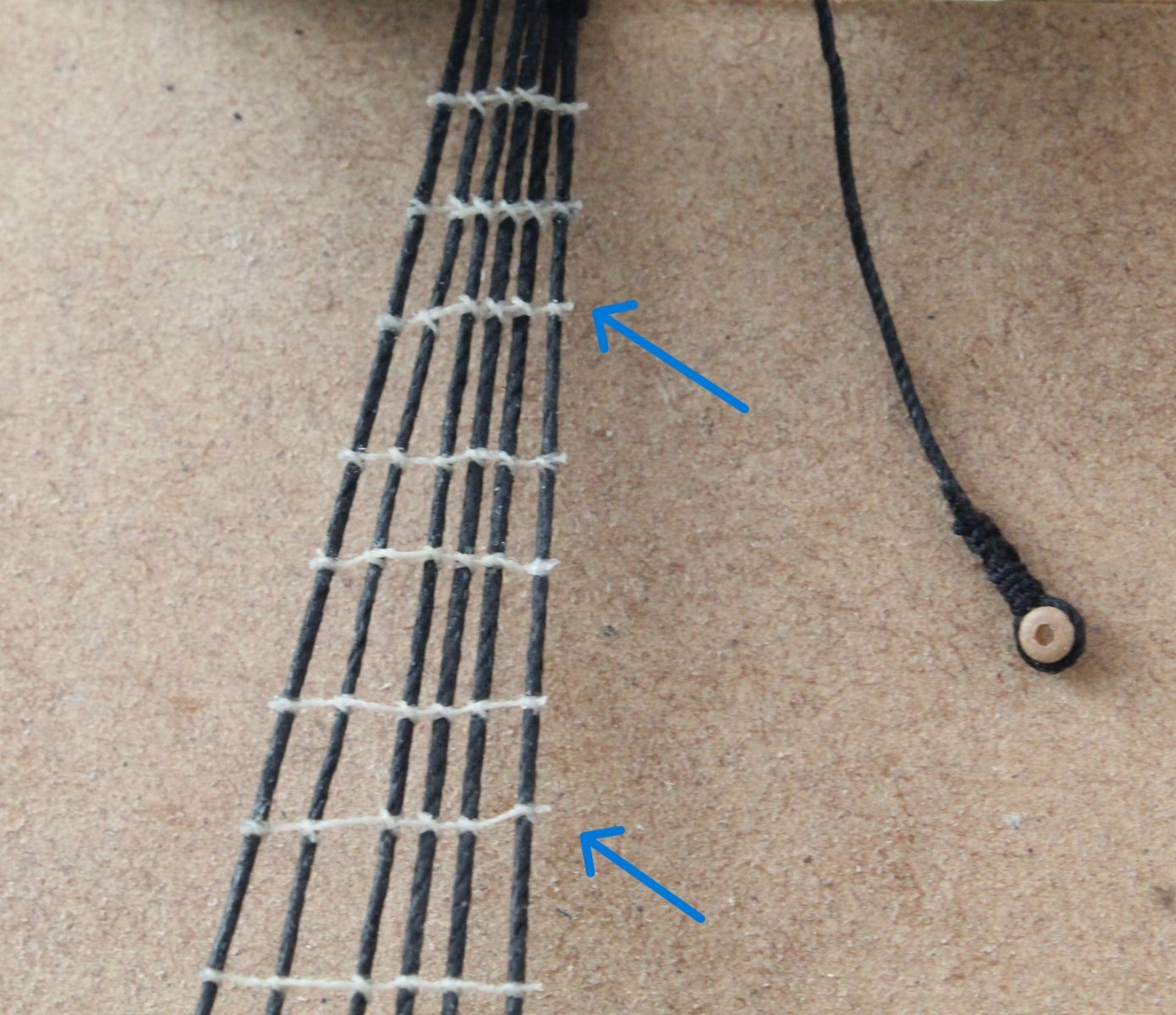
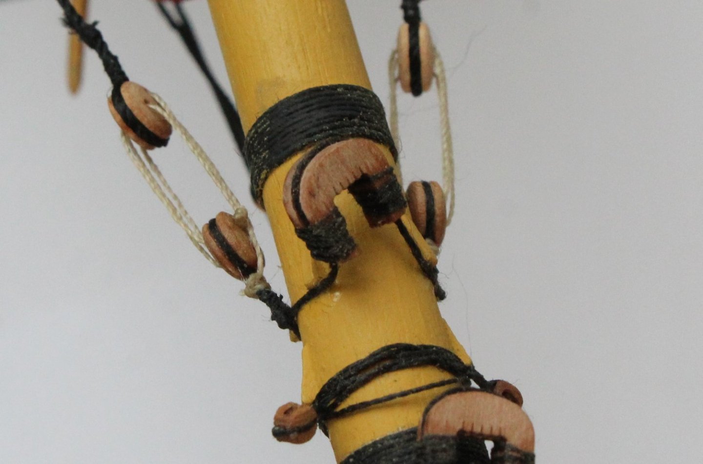
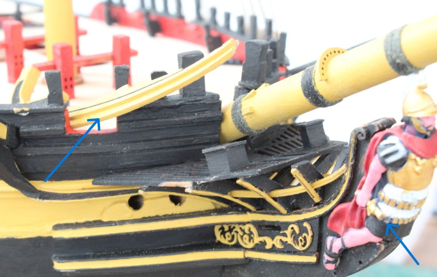
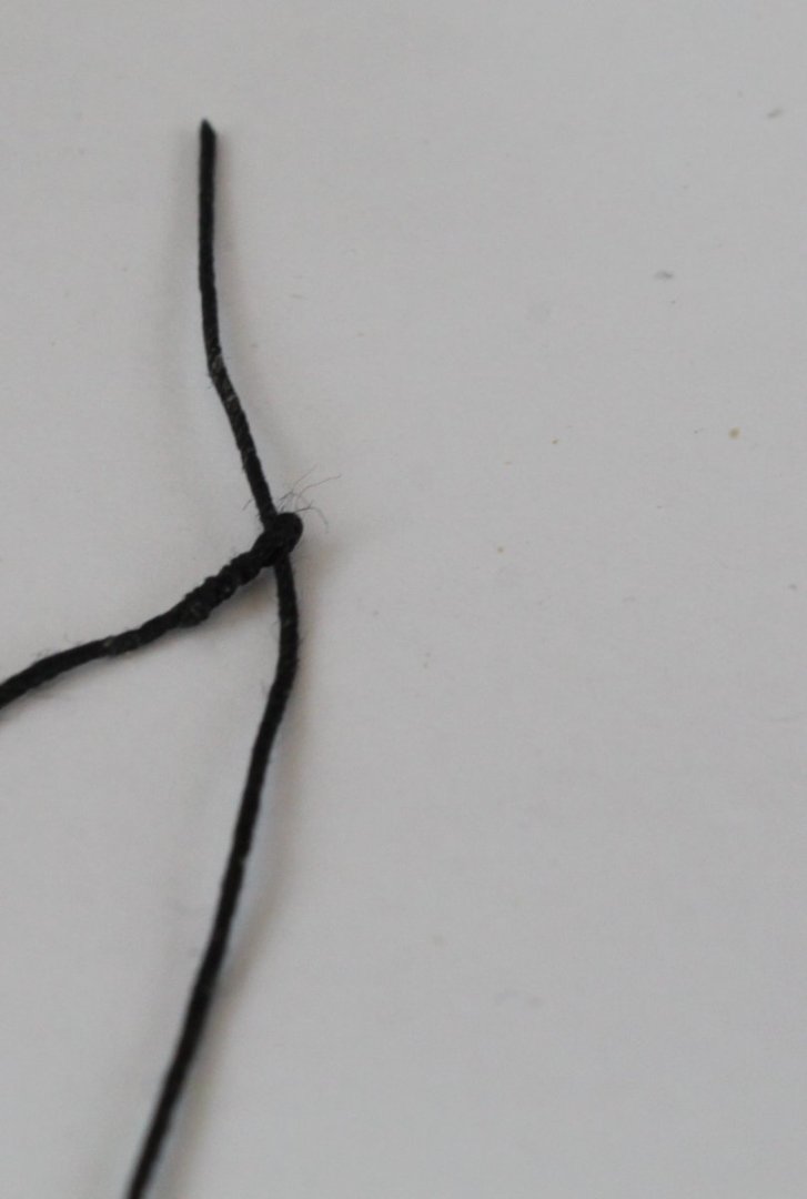
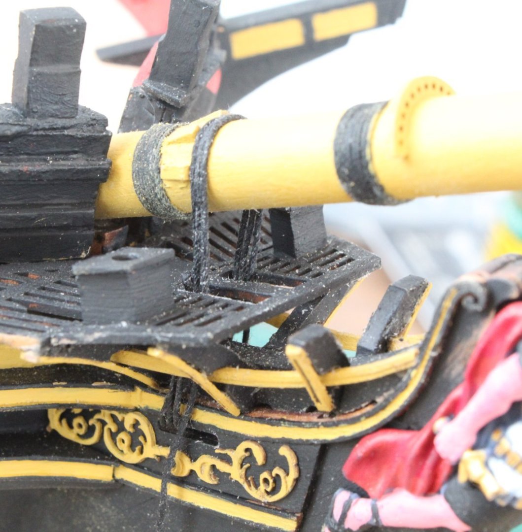
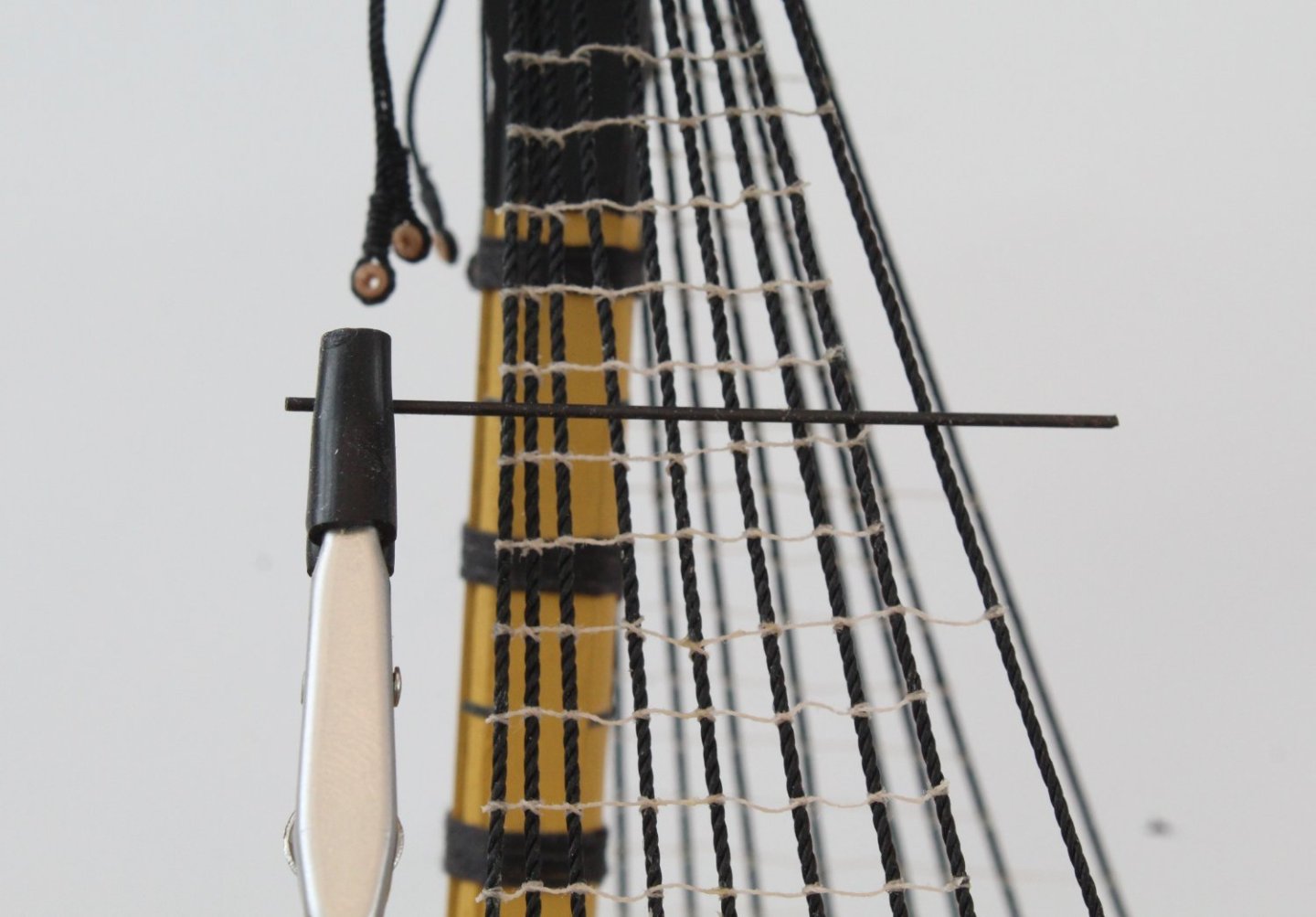
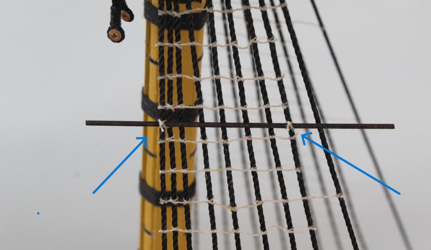
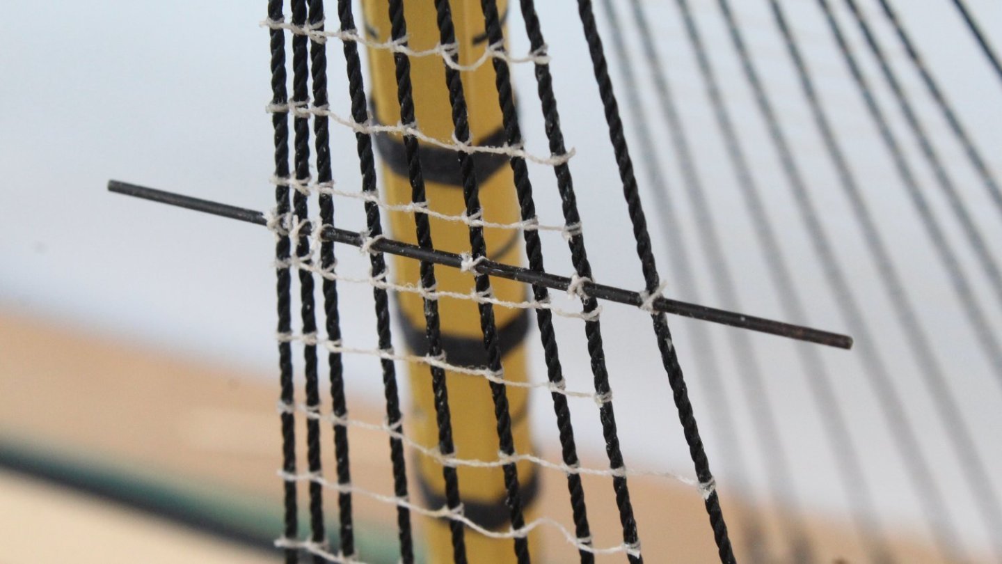
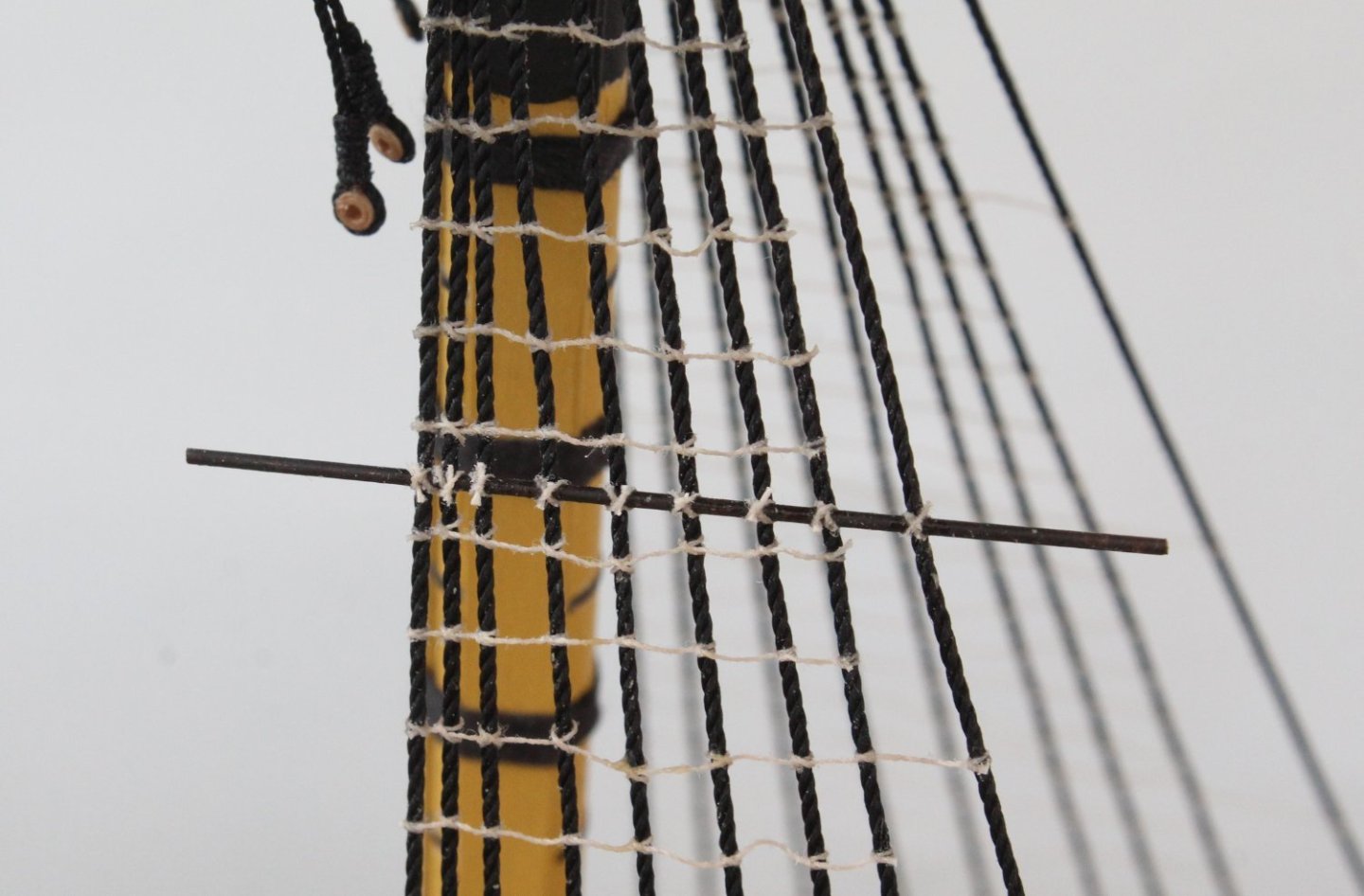
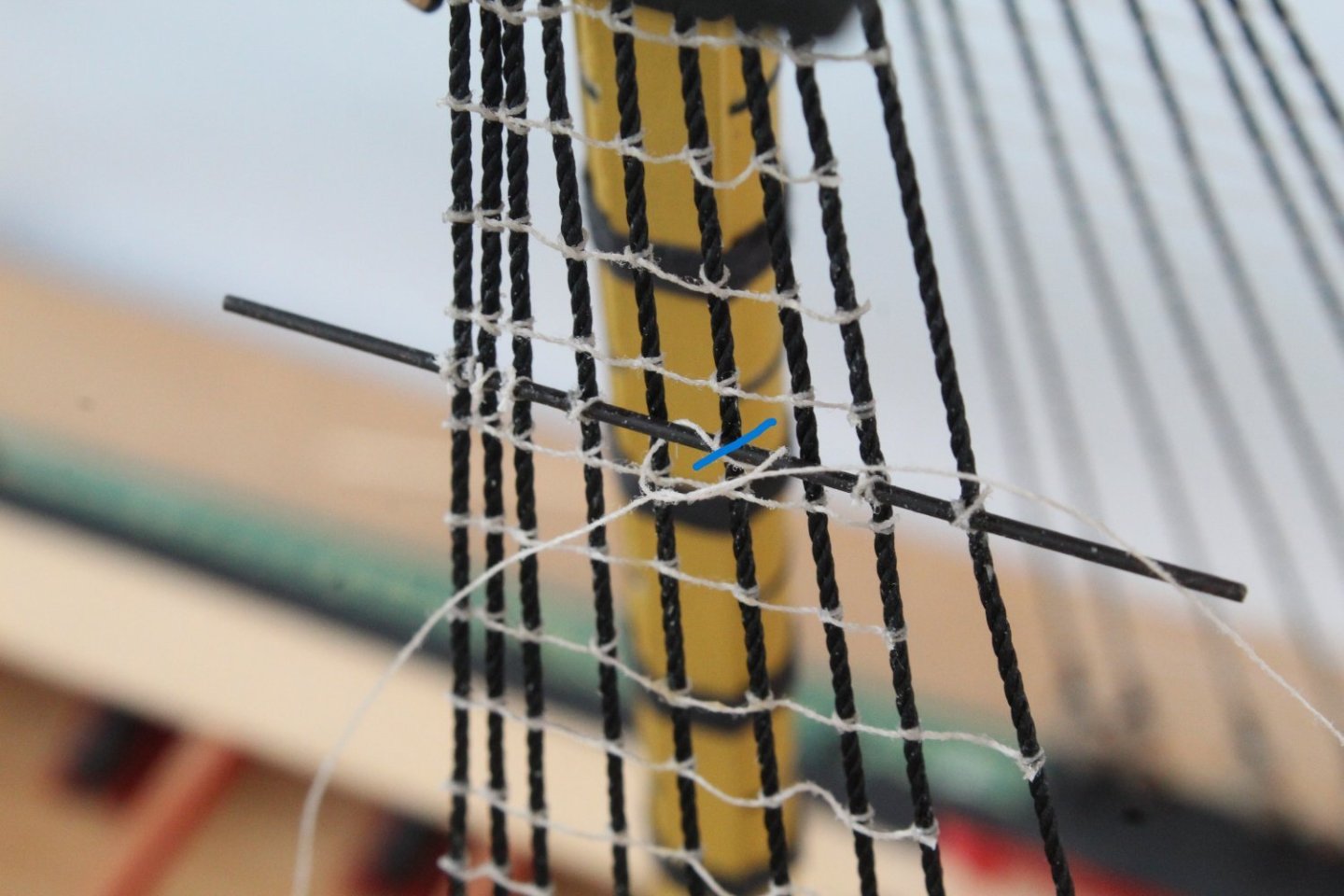
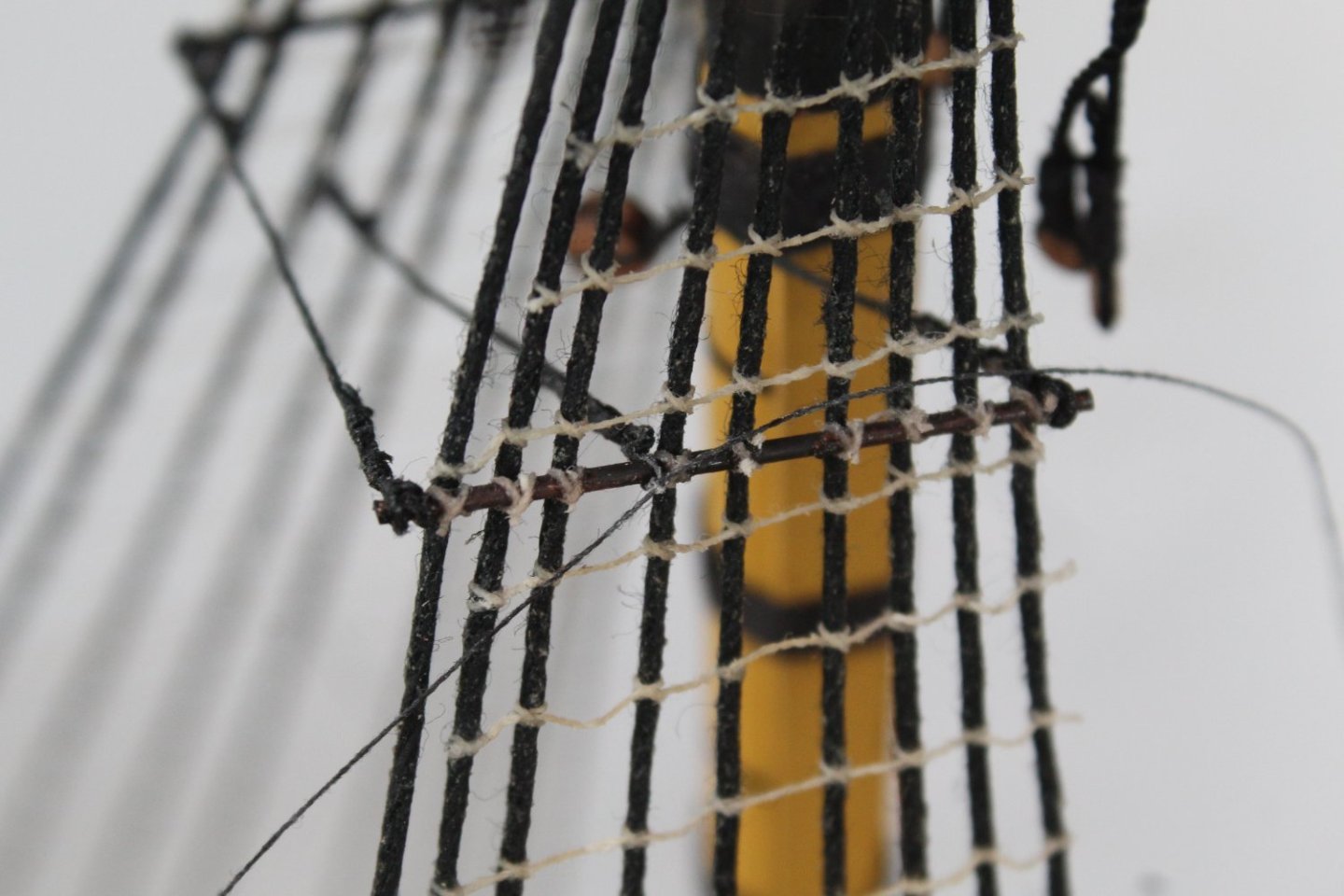
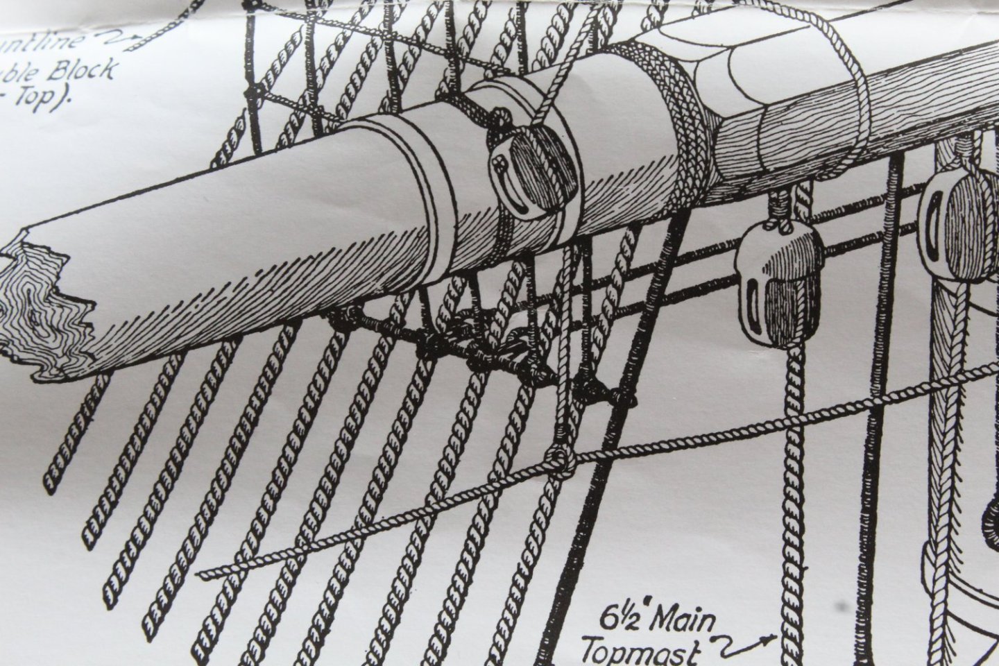
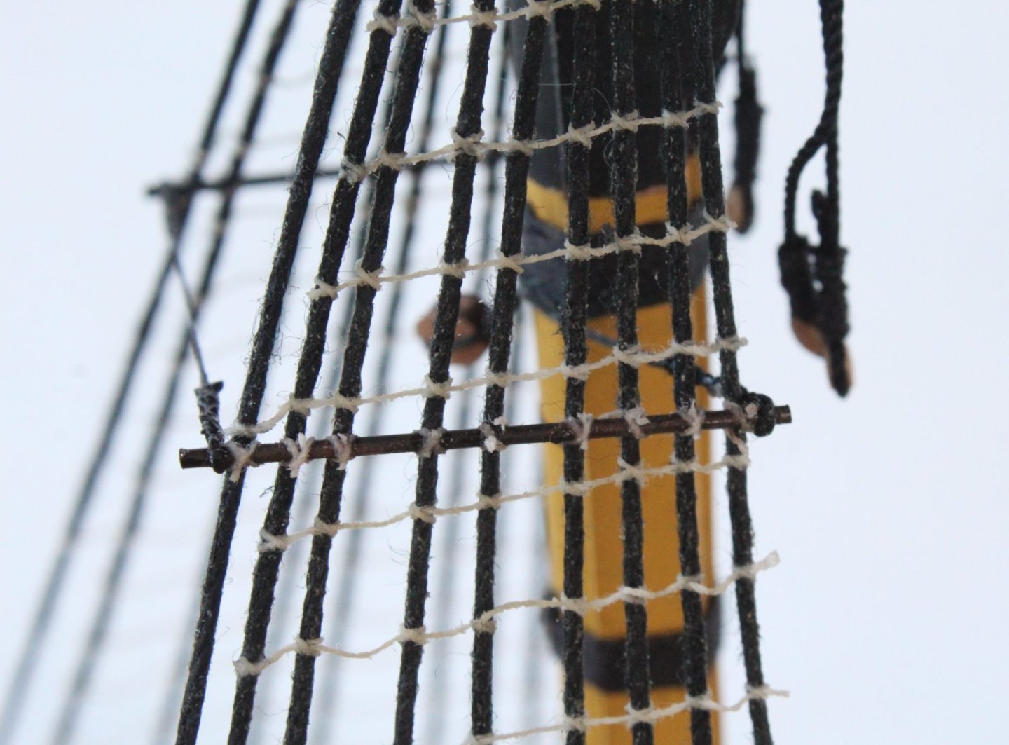
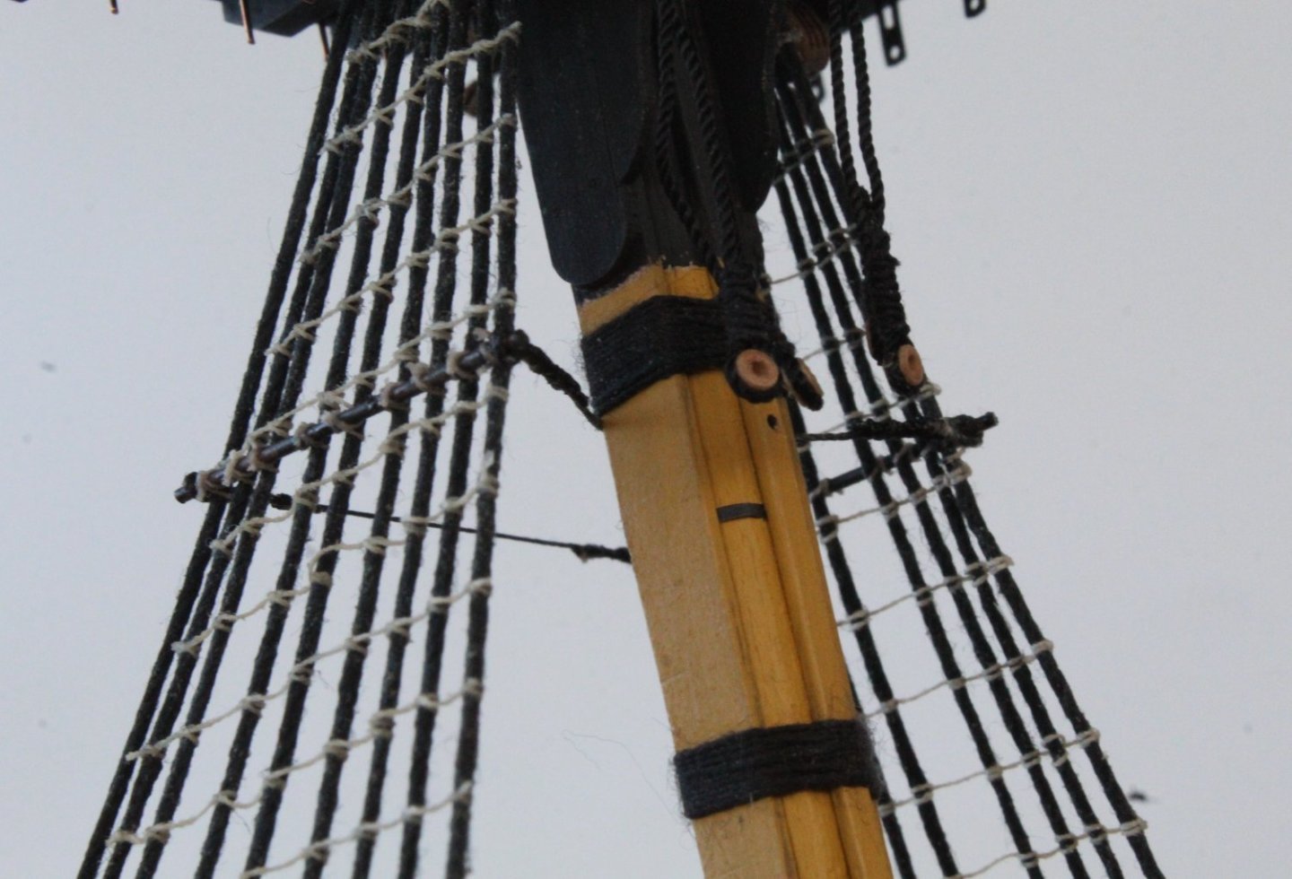
Adding Futtock Staves to Main Mast I have now added the futtock staves to both the main and mizzen masts. I have attached a series of photos of the process I use. I placed a length of blacken brass rod in my quad hands and positioned it against the shrouds in it required position. The brass rod is oversized and will be trimmed once the catharpins have been added. The copper rod is then secured to the shrouds in two places, as indicated by the blue arrows. Once this is done the quads hand can be removed. It is then a process of securing the the brass rod to each of the shrouds. I use a figure of 8 pattern for this. To do this the first diagonal is made using a overhand knot. The direction of the tied knot, when tightened is indicated by the blue line The two free end are then repositioned so second overhand knot can be tied and the direction of the knot, when tightened, is shown by the blue line. After a touch of ca is then applied to the knots and the free ends are then trimmed. It did not take too much time or effort to complete the task.

- 587 replies
-
- 8
-
-
- Indefatigable
- Vanguard Models
- (and 1 more)
-
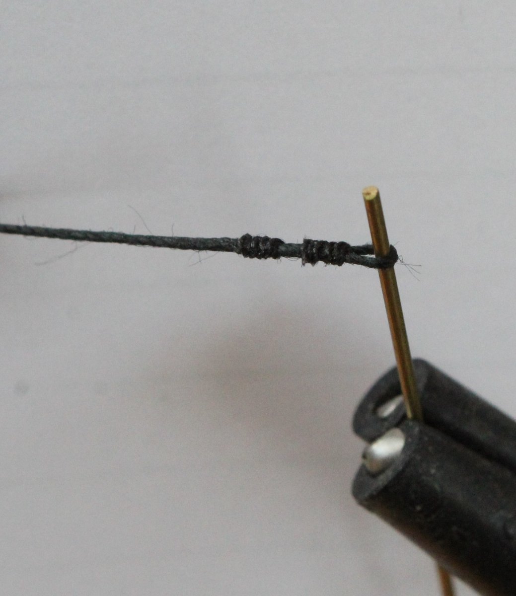
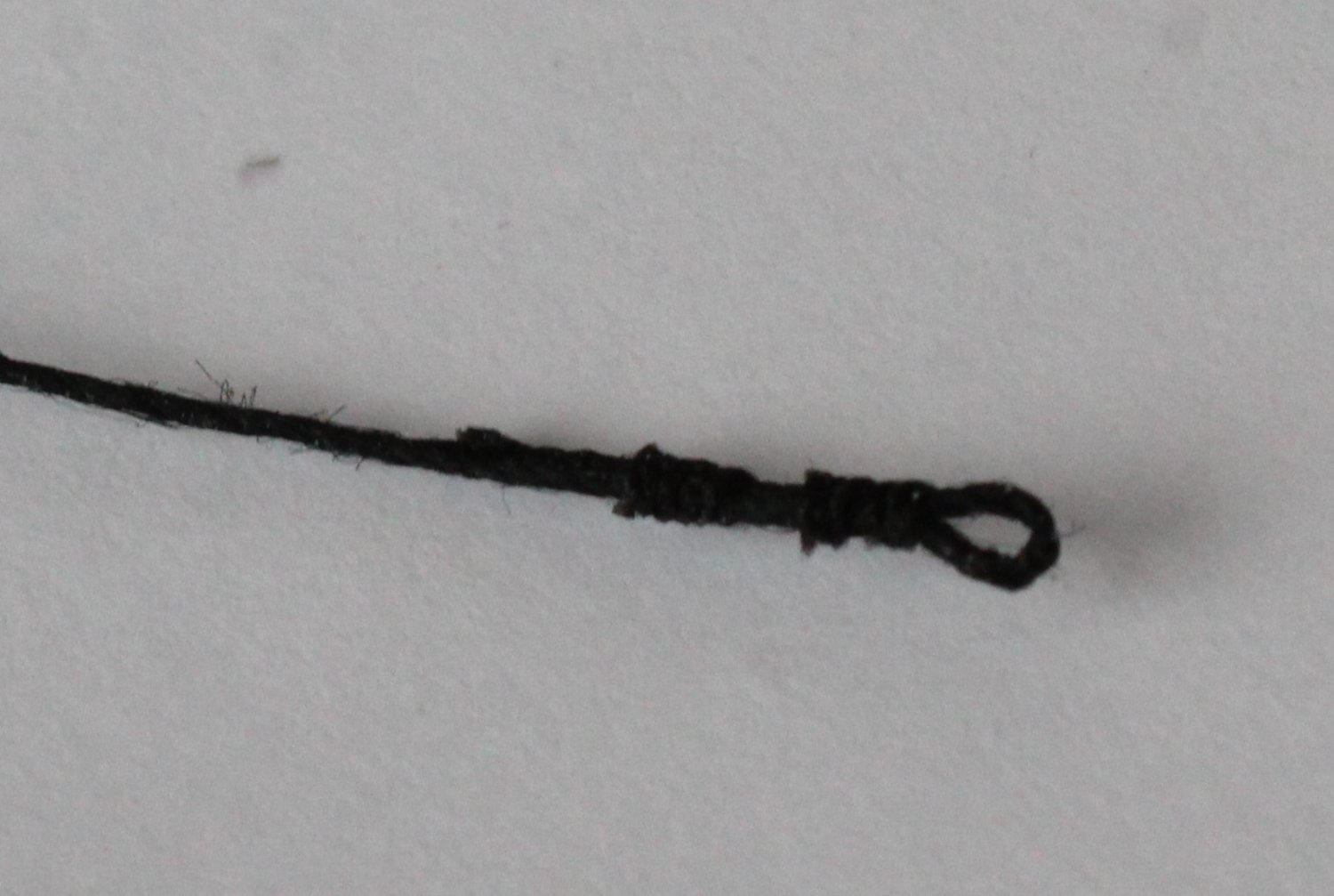
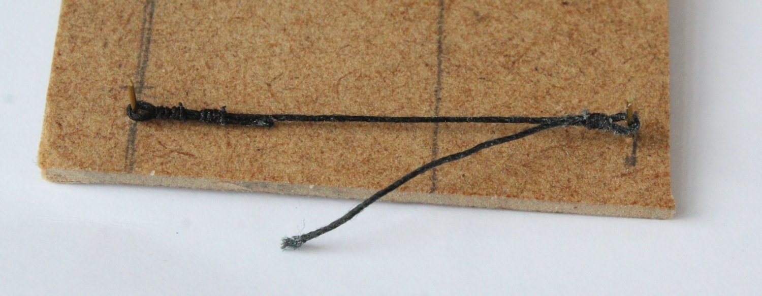
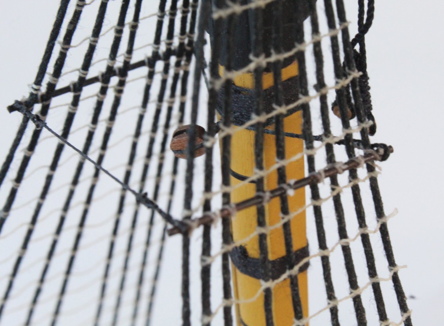
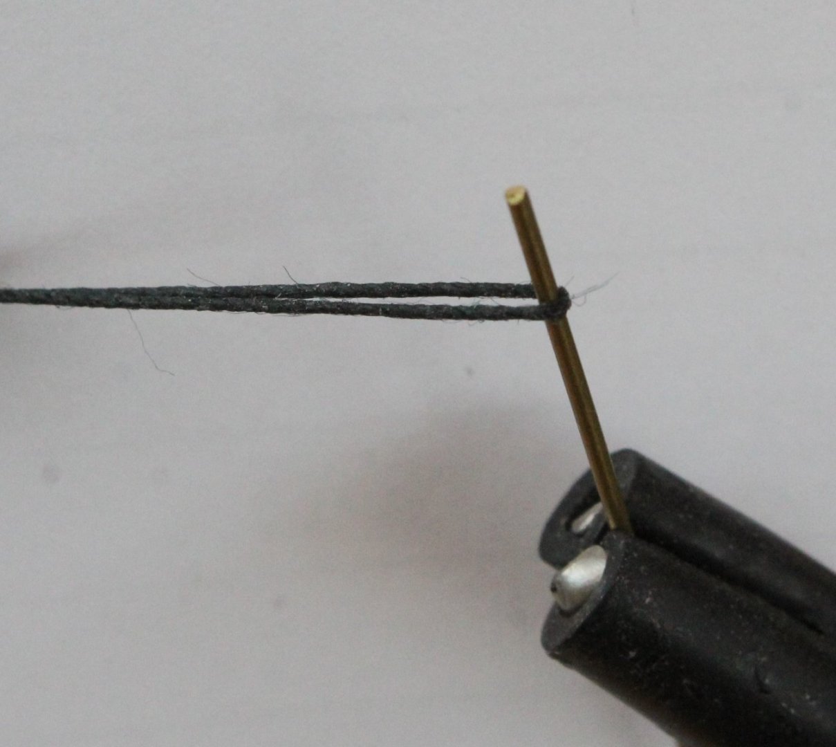
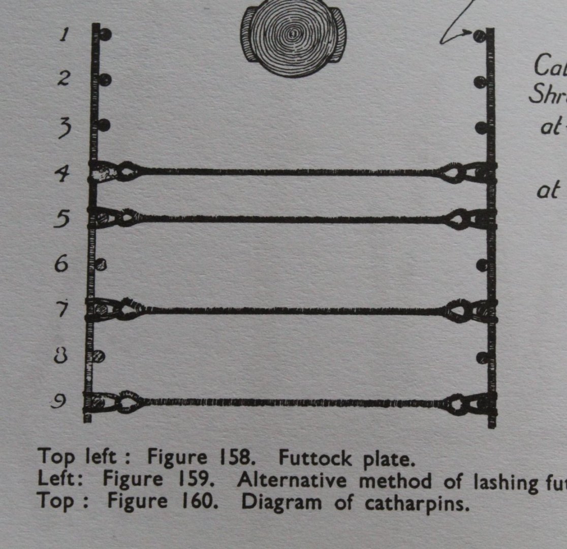
Fitting the inner foremast catharpins I thought I would share the method I have used to fit the two inner catharpins for the lower foremast. This method has worked really well for me. When looking at method for how these were fitted the two diagrams shown in Longridge's book indicates the catharpins had thimbles (loops) at each end. Seizing thread was then passed through the loops to secure to the futtock stave. As per @Blue Ensign comment above the leading catharpin should not really be secured to the first shroud position and then bent around the mast. Step1 - Making the first loop I cut a length of 0.5mm black thread a wrapped it around a copper bar to create a loop. Step 2 - Add first seizing I opted to use 0.1mm black thread and added the seizing. I think it may have been better to used fly tying thread for the seizing in hindsight. Step 3 - Add the second seizing As shown on the rigging plans there are two seizing's required. The thread is removed from the quad hands and a touch of ca glues was used to stiffen the loop. Step 4 - Create the second loop Using the same method as before the loop at the other end of the catharpin was created. I had made a simple jig to set the required length of the inner catharpins. Once the first seizing of the 2nd loop had been added the catharpin was place on the jig. The position of the seizing was carefully adjusted until the require length was achieved. Step 5 - Completing the Seizing The catharpin was returned to the quad hands so the seizing to the to the 2nd loop could be added. Once that was done the catharpin was held taut in quad hands and a light diluted coating of pva was applied. A hairdryer was then used to to quickly dry the diluted solution. Step 6 - Adding the thread to the loops A length of 0.1mm black thread were added to each of the catharpin loops. Step 7 - Fitting the catharpin to the futtock stave The flying leads are then thread over and under the futtock stave and secured using a standard reef (square) knot. Step 8 - Repeat the process for the other inner catharpin A second catharpin was made using the exact same method as detailed above and added to the foremast futtock stave.

- 587 replies
-
- 12
-
-
- Indefatigable
- Vanguard Models
- (and 1 more)
-
Very informative and many thanks for the heads up. I really like research like this as it really helps improve my limited knowledge base.😀 I will leave as fitted for my Indy build as I am happy with the alignment of the futtock staves and once fully rigging it will not be that noticeable.
- 587 replies
-
- 1
-
-
- Indefatigable
- Vanguard Models
- (and 1 more)
-
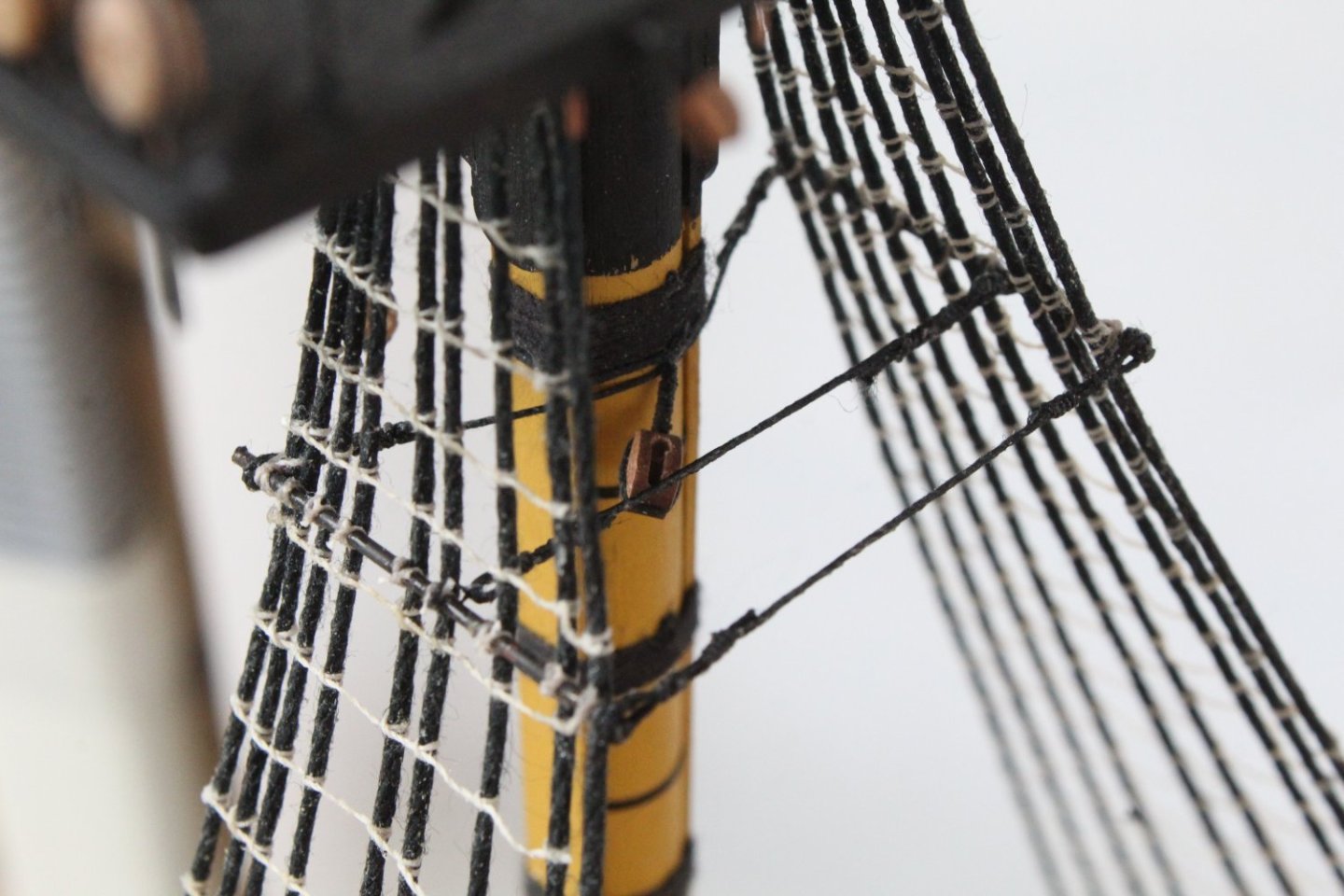
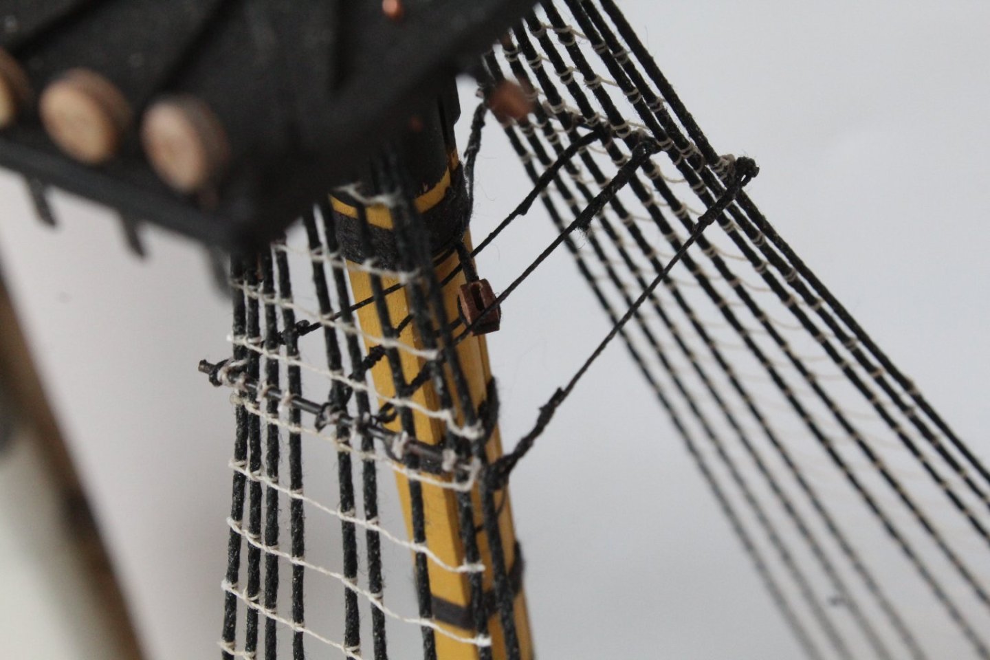
Foremast Futtock Staves and Catharpins One of my least favorite rigging tasks is adding the futtock staves and catharpins. Adding the futtock staves to the lower foremast actually turned out to be a relatively simple and painless task. After chemically blackening two lengths of material the futtock staves were held in position using my quad hands. Once I had tied the futtock stave to the two outer shrouds using a figure of 8 pattern the quad hands were removed and the remaining shrouds secured. The shroud pairs are to be linked together with 4 catharpins. I opted to run the futtock staves parallel with each other therefore after careful measurement I decided the required length was 45mm for the aft and 50mm for the leading catharpin. The leading one needs to be longer as it has to fit behind the foremast. Before they were fitted I did coat them with diluted wood glue and then dried them off with a hair dryer to get help with the look of tautness. With these two catharpins in place I am pleased with how they look. The two inner catharpins still need to be added.

- 587 replies
-
- 13
-
-
-
- Indefatigable
- Vanguard Models
- (and 1 more)
-
Many thanks. I agree is does look great as is, however I will push on to complete all the masts, yards and associated rigging even though I am itching to start another model but I will try to remain patient. Hoping the Indy will be completed in the next few months. Your Indy looks amazing, excellent building skills.
- 587 replies
-
- 5
-
-
- Indefatigable
- Vanguard Models
- (and 1 more)
-
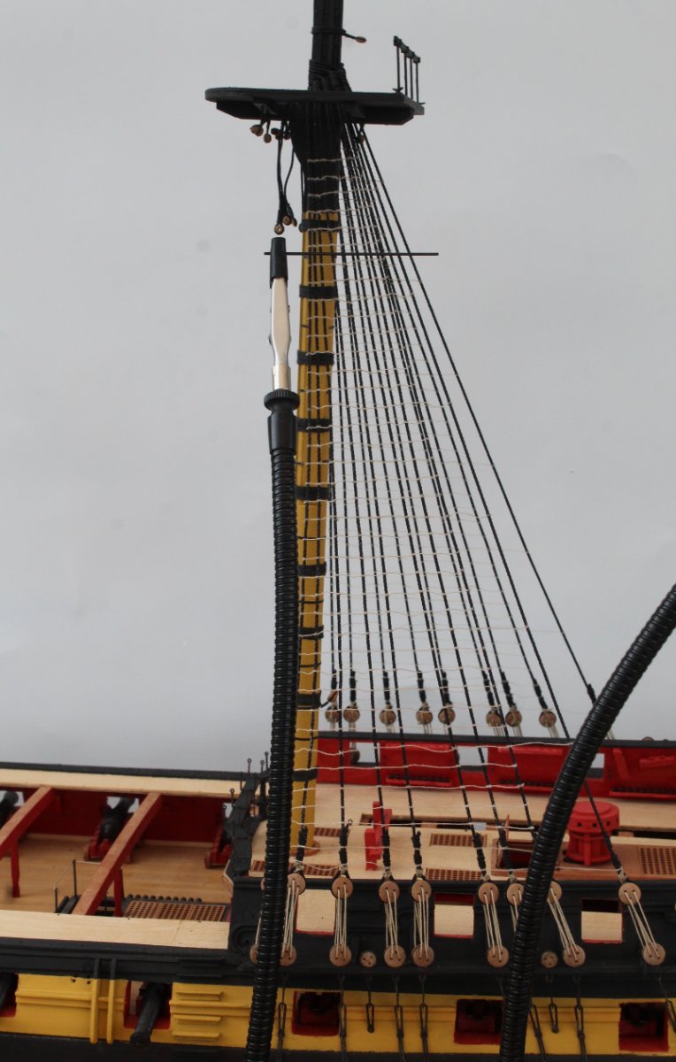
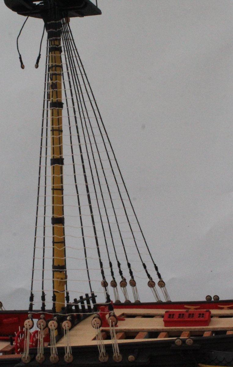
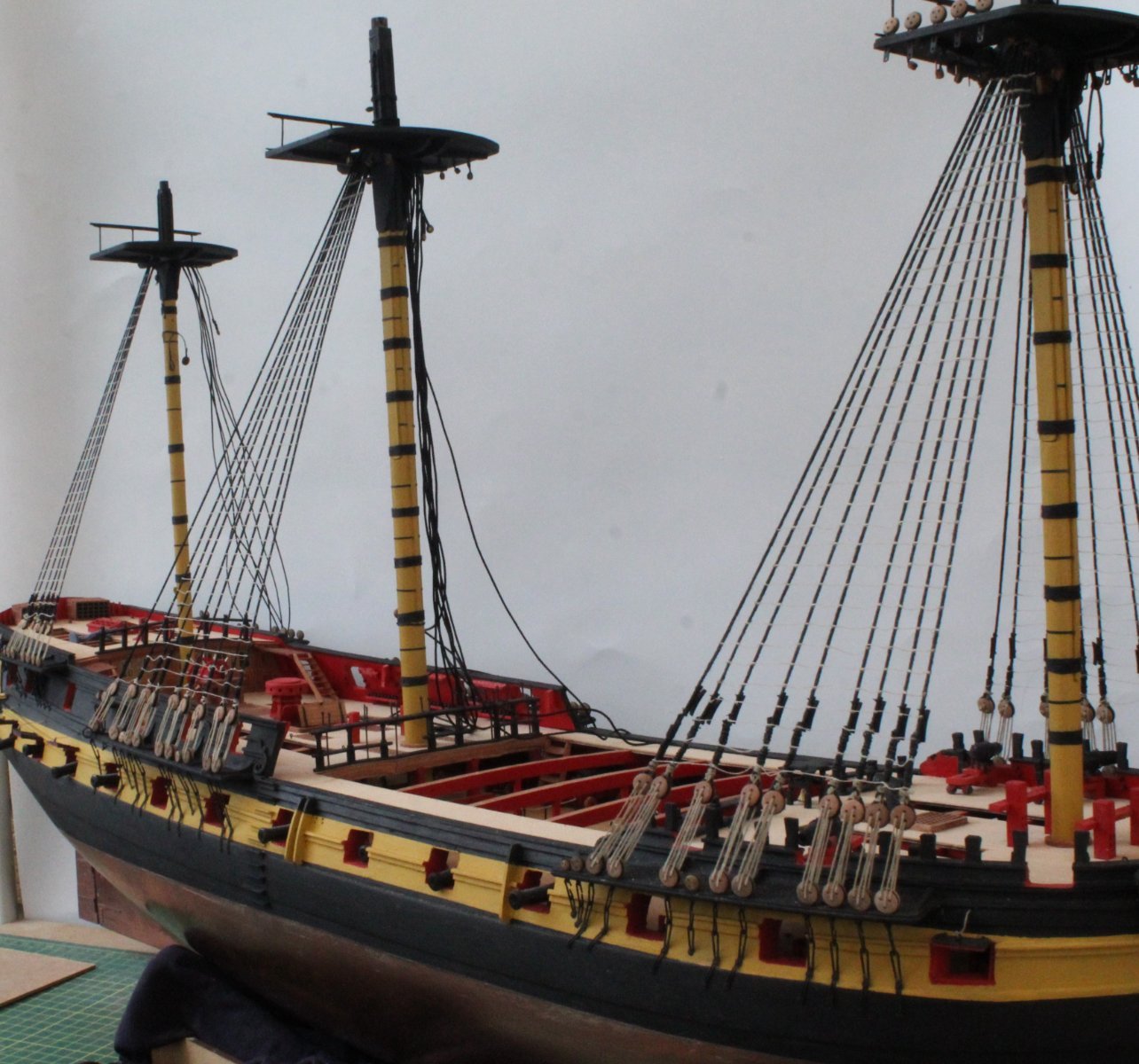
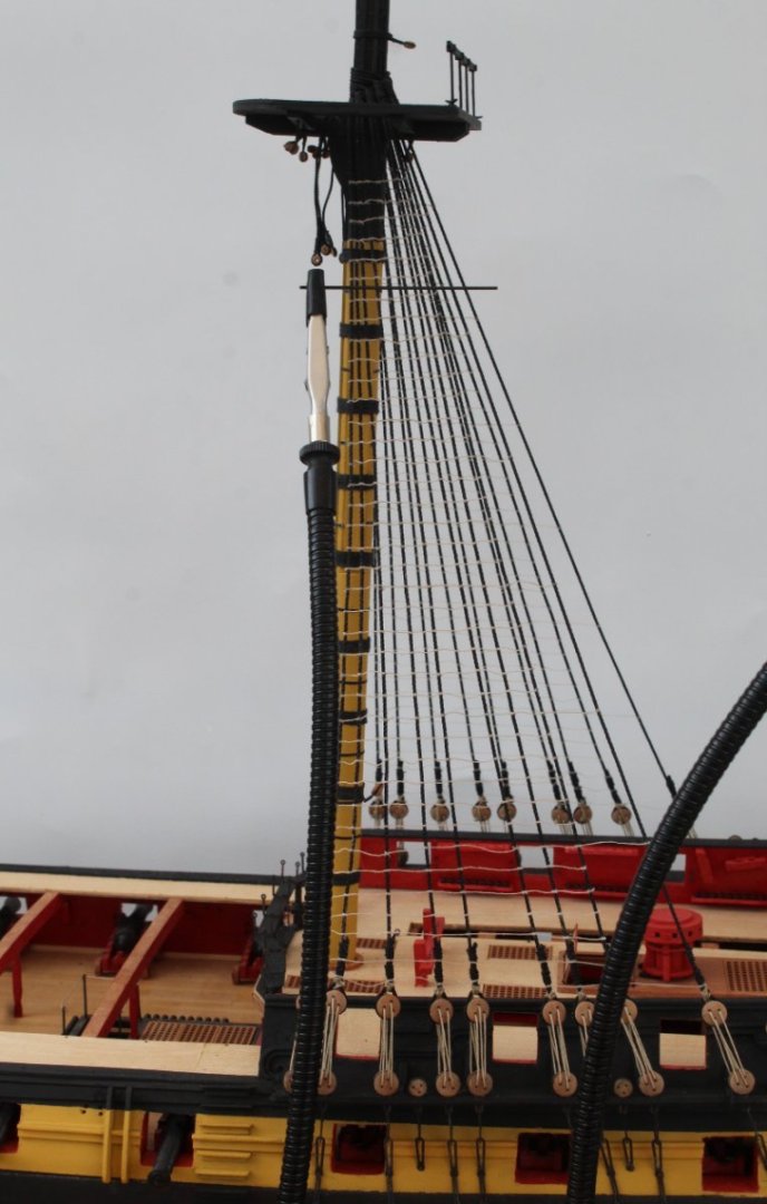
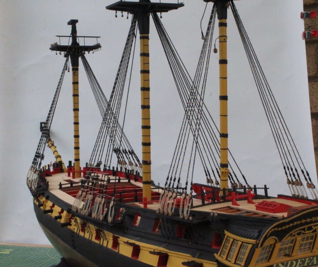
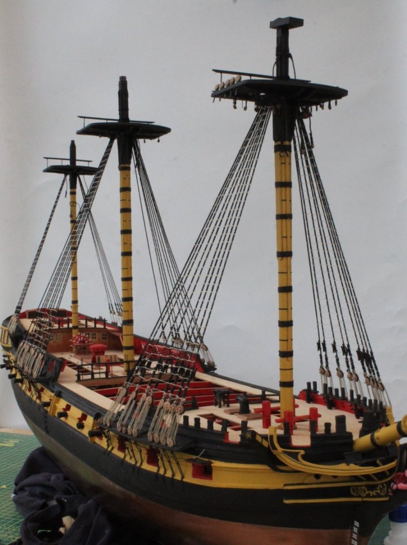
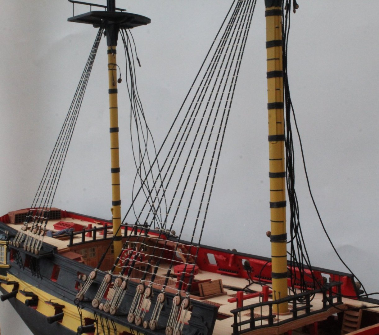
Lower Masts Shrouds and Ratlines Completed Today I tied the final clove hitch knot required for all the lower masts ratlines. I feel like a huge weight have now been lifted of my shoulders now this task is complete. I am very happy with how the shrouds and ratlines look apart from the left-hand side main mast which has a slight kink on the lower lead edge section. I do not have the inclination or patience to remove the ratlines and redo as I suspect I will be the only one to see the defect once the model is complete. My next job is one of my least favourite rigged tasks which is to add the futtock staves and catharpins to each of the lower masts. I have been contemplating how to go about this to make it easier to complete. I have an idea with regards to adding the futtock staves which, if successful, should make it a relatively painless and simple task to complete. I also have a couple of ideas with how best to fit the catharpins which I will experiment with before trying to add them to the Indy. I have added a few photo's of the current build status.
- 587 replies
-
- 12
-
-
- Indefatigable
- Vanguard Models
- (and 1 more)
-
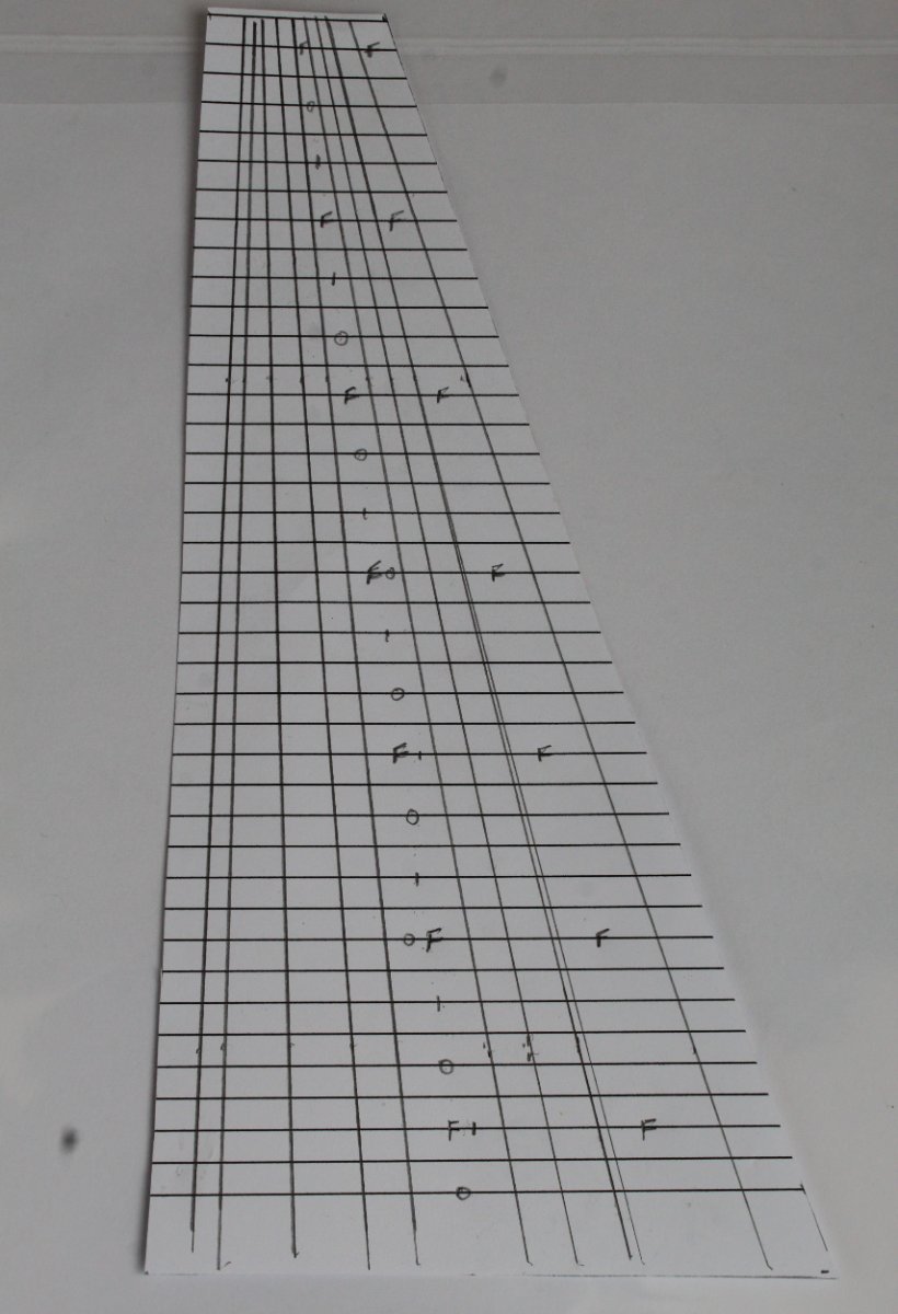
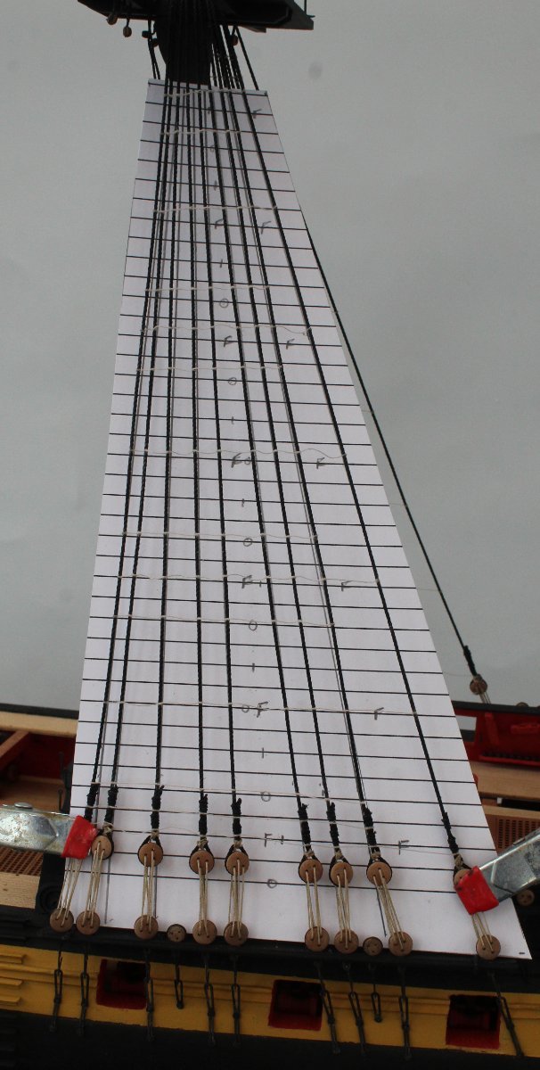
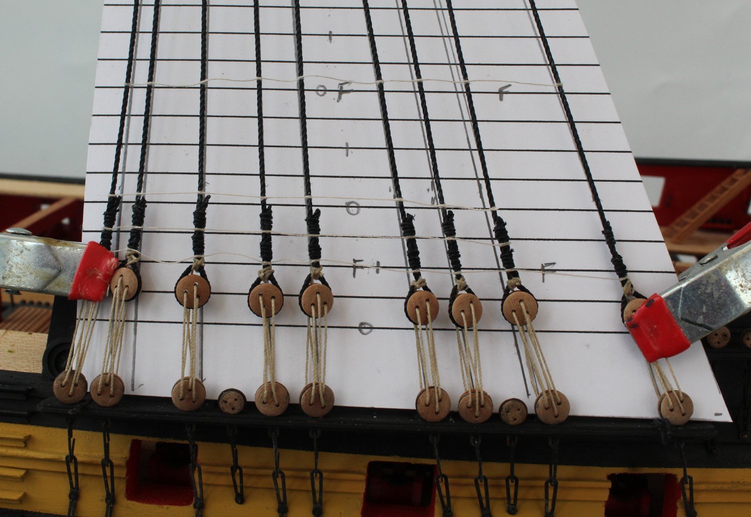
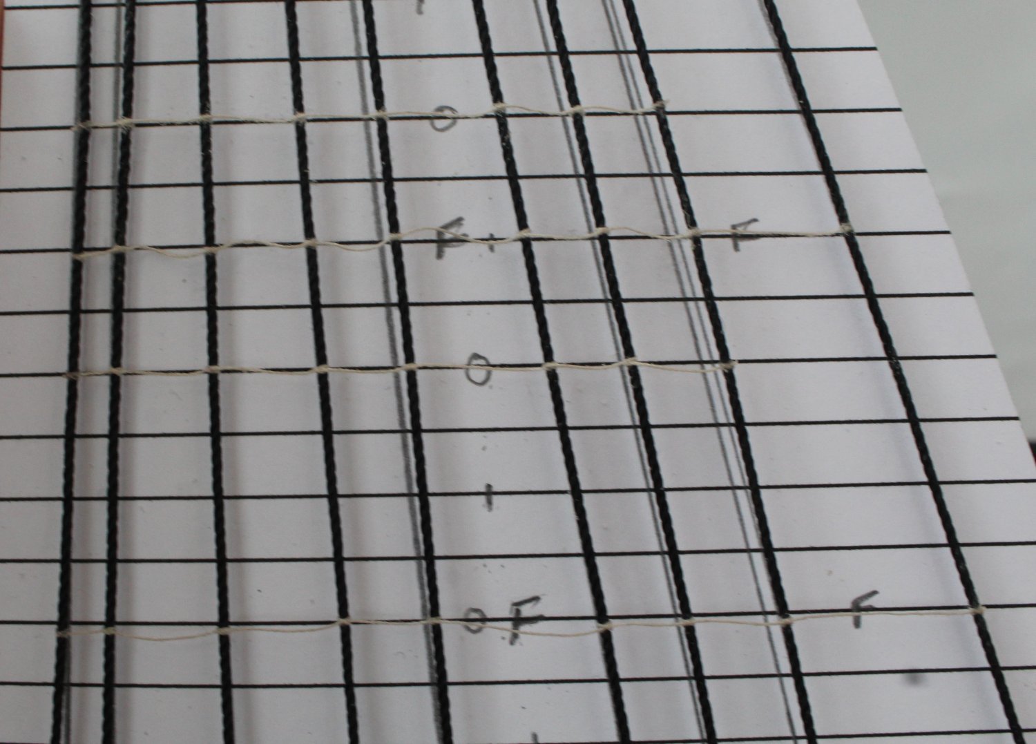
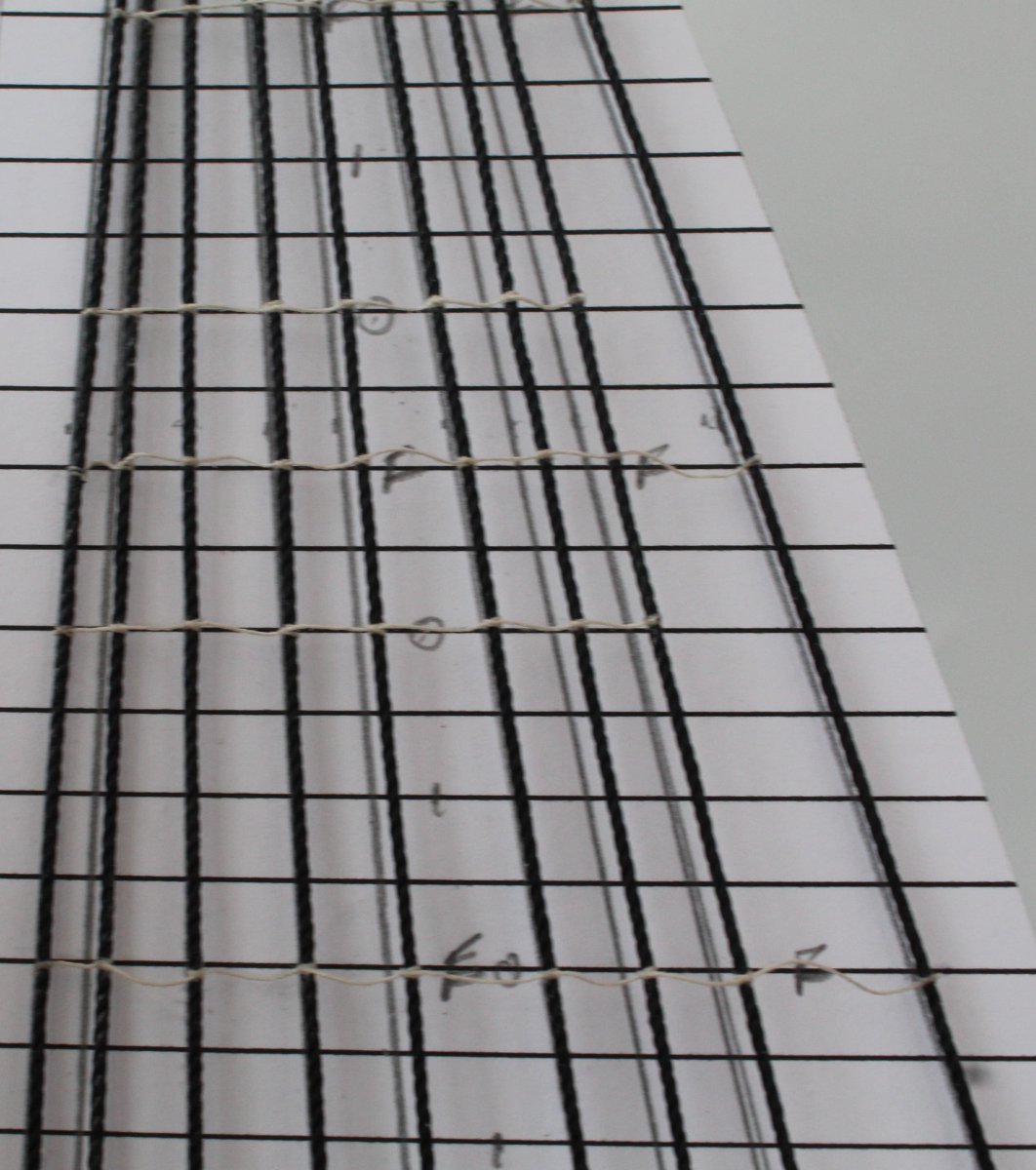
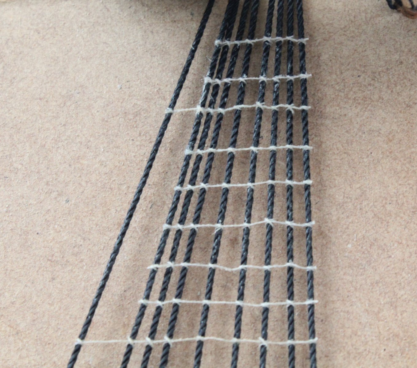
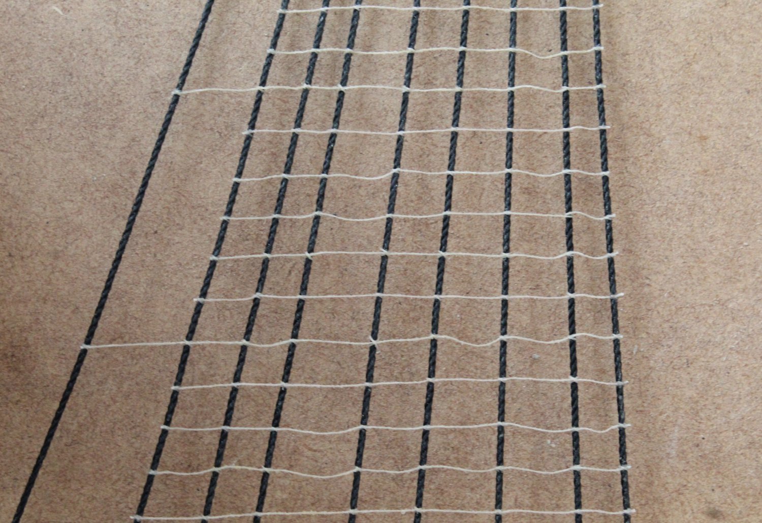
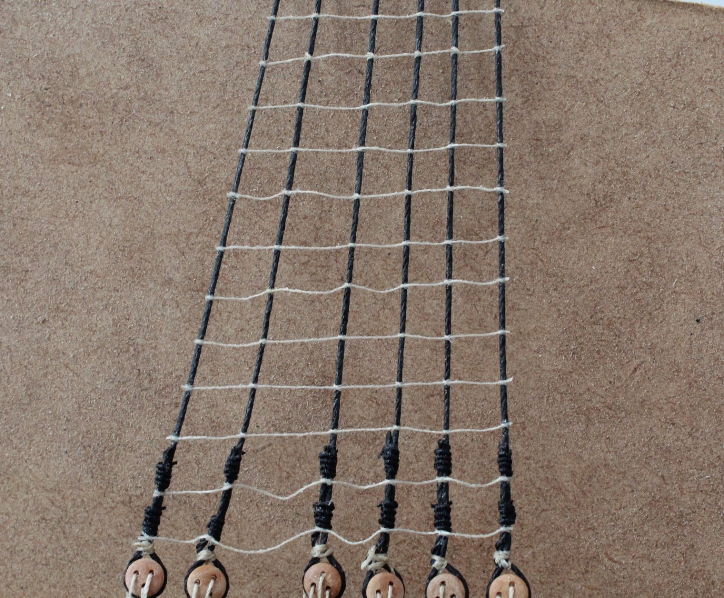
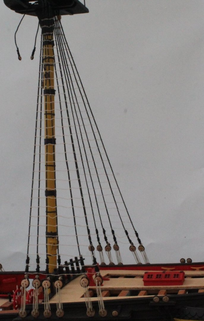
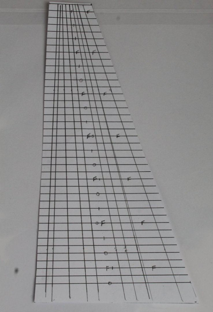
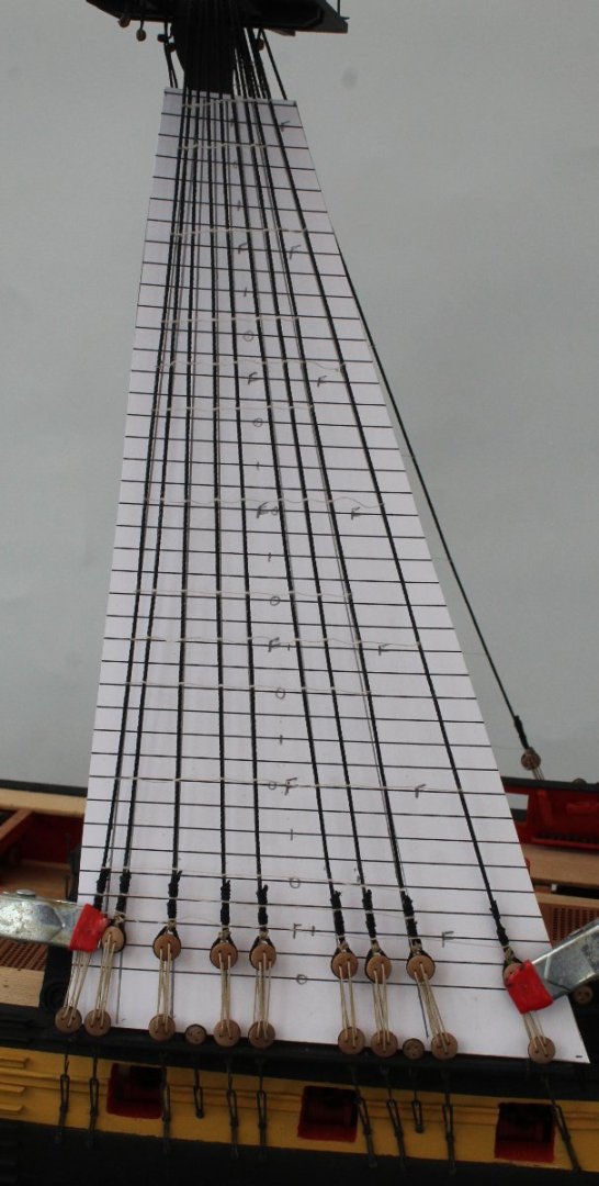
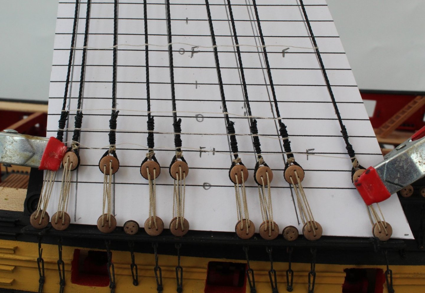
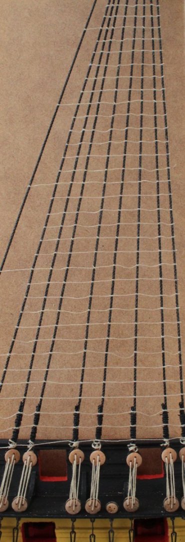
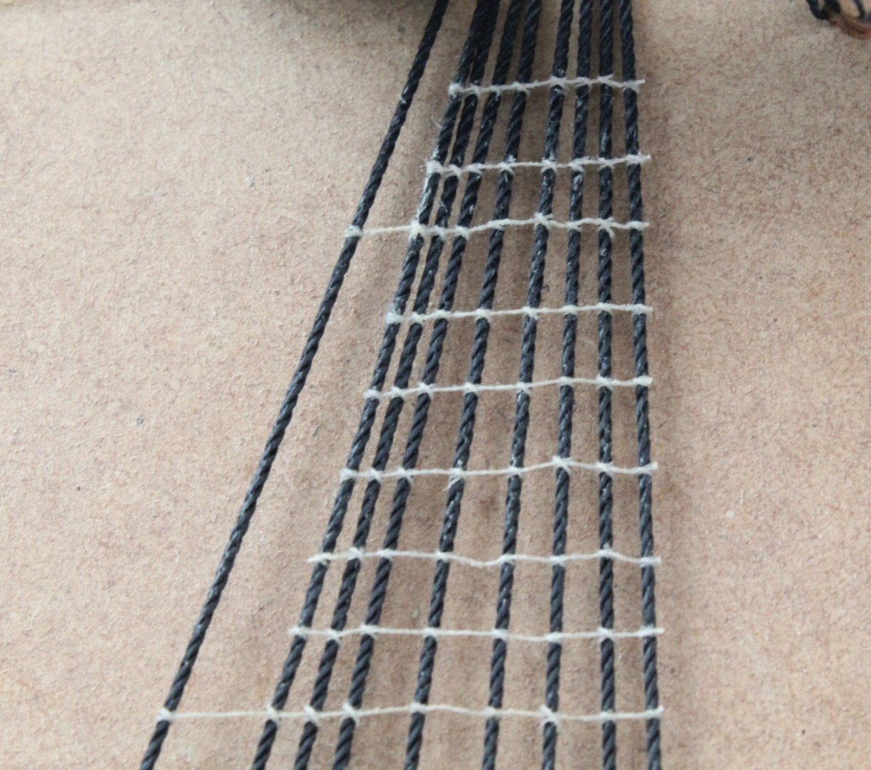
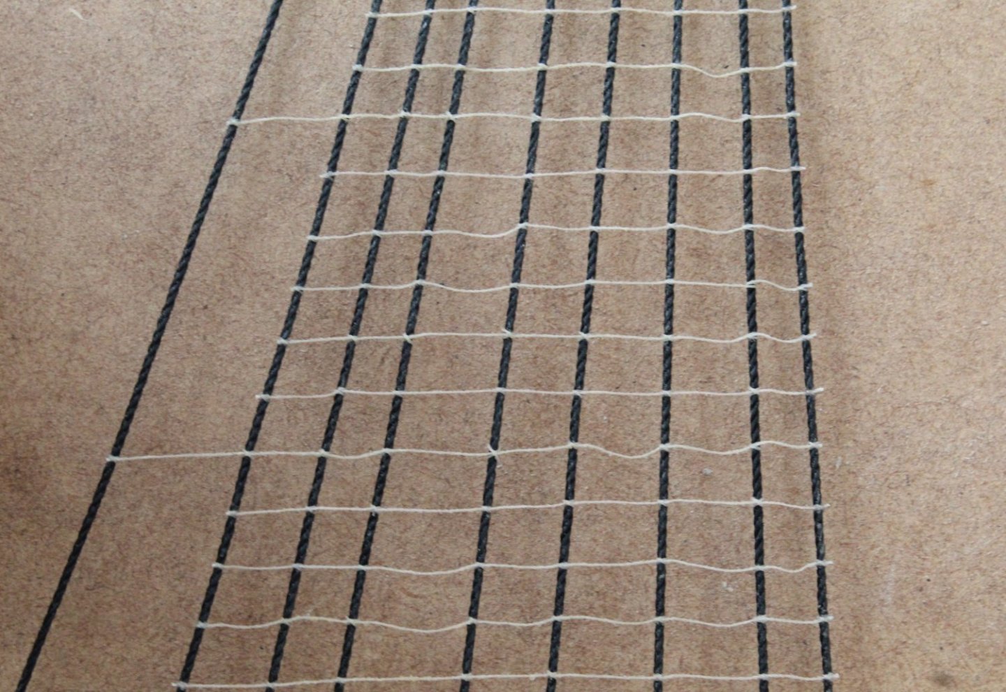
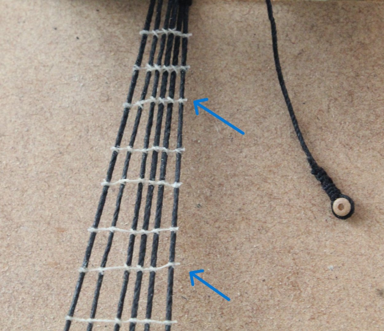
Left-Hand Side Main Mast Ratlines After a short break from the Indy, due to a visit to Manchester to see a great concert at the Lowrey plus a visit to see two of the six grandkids, I made a return to the shipyard. The lanyards were tied off and the free ends of the shrouds seized. I then prepared the template for ratlines. I marked the approx run lines of the shrouds. These are a useful guide and helps prevents the dreaded hourglass effect. As indicated in previous posts my preferred method is to start with adding all full length ratlines (every 7th one). I added a F reference on the template. Once all the F's have been added I like to add every 5th ratline, indicated by a 0 on the template. Next with the middle ratlines between every 5th one, marked with a 1 on the template. The template is then carefully aligned and clamped in position. The next photo shows the shroud seizing's and lower ratlines. You will note I have added the F and 0 ratlines. More photos of the progress of the F and 0 ratlines. They have all been added so on my next shipyard visit I can start work on the 1 ratlines.
- 587 replies
-
- 11
-
-
- Indefatigable
- Vanguard Models
- (and 1 more)
-
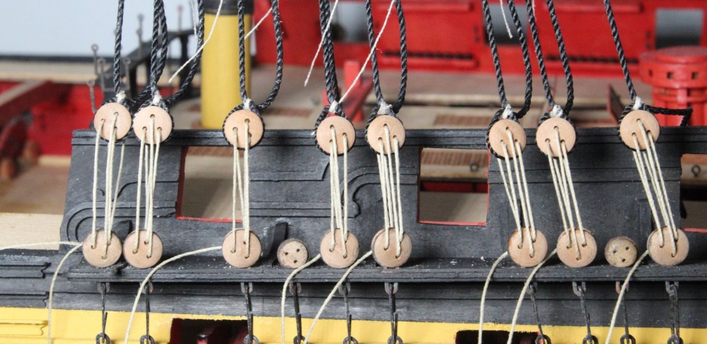
Adding deadeyes to shrouds Following on my from last post I thought I would detail how the deadeye is seized. Step 1 With the jig in play a length of seizing thread is pushed through the shroud line, with the aid of a needle. Step 2 Using the quad hands the seizing loop is formed. Step 3 Using a simple cross over knot the loop is secured. Step 4 The two free ends of the seizing thread are looped around and another simple crossover knot is formed. Step 5 The two free ends of the seizing thread are passed through the loop once again Step 6 Another simple crossover knot is used and the seizing process is complete. Step 7 Once the free ends of the seizing thread have been trimmed the loop can be pulled tight around a deadeye. Step 8 As each deadeye is seized the lanyards are added to check the alignment. As can be seen in the next series of photos the jig and seizing method has worked well as the shroud deadeyes are nicely aligned. I will adjust the rotation of some of the shroud deadeyes when it is time to tie the lanyards off.


- 587 replies
-
- 14
-
-
-
- Indefatigable
- Vanguard Models
- (and 1 more)
-
Modified Deadeye Jig Before commencing work on adding the deadeyes to the left-hand side main mast shrouds I decided to improve the jig used to set the position of said deadeyes. Using the two locating pins the jig is placed on the first channel deadeye. With reference to the blue arrow on the photo below the shroud is then brought down placed between the alignment pins. The modification to the jig was adding a hole at the bottom, as shown by the yellow arrow. The shroud is then passed through the hole and held in place with a clamp (red arrow). The addition of the hole helps to keep the tension in the line when clamped. With the shroud line in place the deadeye seizing thread is then added. Using the same reference point as per the right-hand side I am using the top edge of the jig as the reference point, as can be seen in the photo below (blue arrow). I have added the shroud deadeye seizing thread to all the main mast shrouds in readiness to creating the loops and inserting the deadeyes.


- 587 replies
-
- 10
-
-
- Indefatigable
- Vanguard Models
- (and 1 more)
-
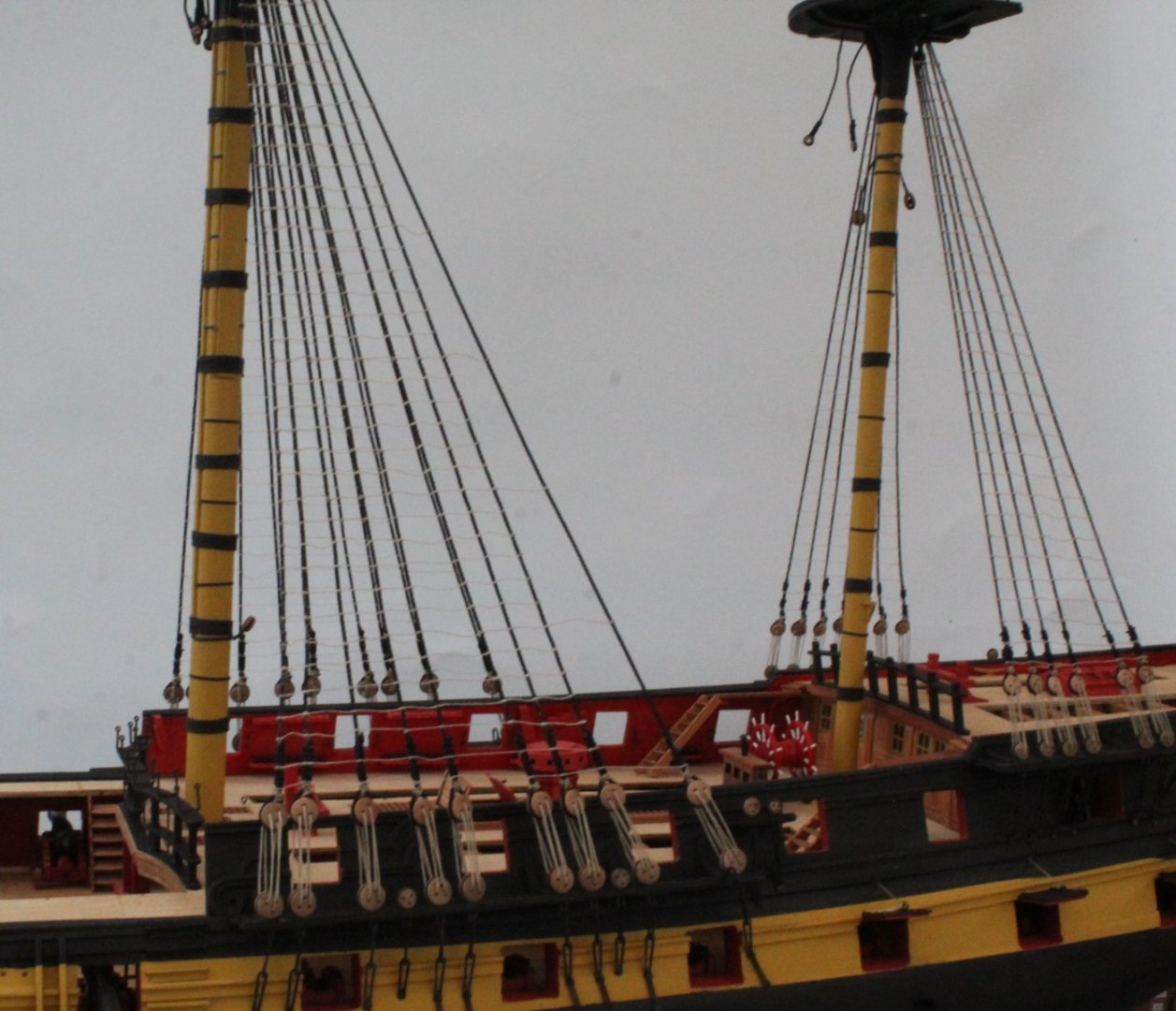
Main and Mizzen Mast Ratlines I have now completed adding the ratlines to the right-hand side of the main and mizzen lower masts. I am reasonably happy with how they look. I have managed to avoid the dreaded hourglass effect and apart from the odd one there is not a great deal of ratline droop between the adjacent shrouds. I am still undecided weather to leave the ratlines beige or to dye them black using Indian ink. I have it all to do again for the left hand side main and mizzen mast. My time in shipyard will be limited over the next few days it might be next week before I can start to make progress. When taking the photo's below I used some scrap wood to try to show the ratlines. Main Mast Upper section main mast Mid section main mast Mizzen Mast The lower section Mizzen mast top section. I have highlighted a couple of ratlines which I may redo as they do not look good. To complete this post see the following two photos


- 587 replies
-
- 16
-
-
- Indefatigable
- Vanguard Models
- (and 1 more)