Glenn-UK
-
Posts
3,175 -
Joined
-
Last visited
Content Type
Profiles
Forums
Gallery
Events
Everything posted by Glenn-UK
-
 I use a 50 / 50 mix of white spirit and ronseal clear poly matt varnish. This is wiped on with a cotton cloth. You've done a great job on the mast and yards, etc.
 -
Many thanks Derek. I have used many of techniques you have kindly shared on your build logs which helped me enormously.
- 476 replies
-
- 2
-

-
- sphinx
- vanguard models
- (and 1 more)
-
Many thanks Dave for your support and very kind words.
- 476 replies
-
- 2
-
-
- sphinx
- vanguard models
- (and 1 more)
-
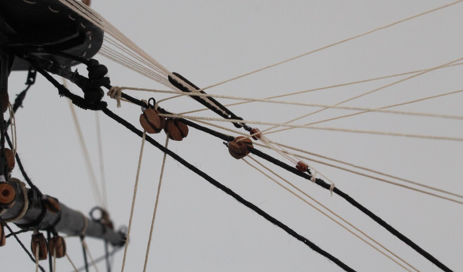
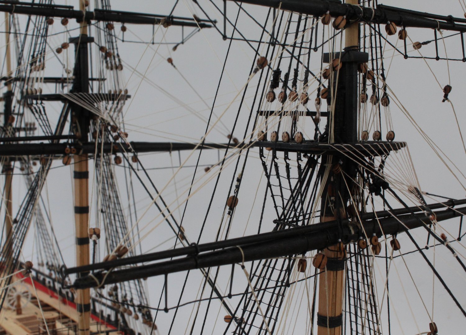
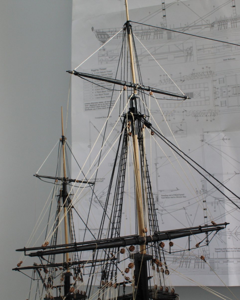
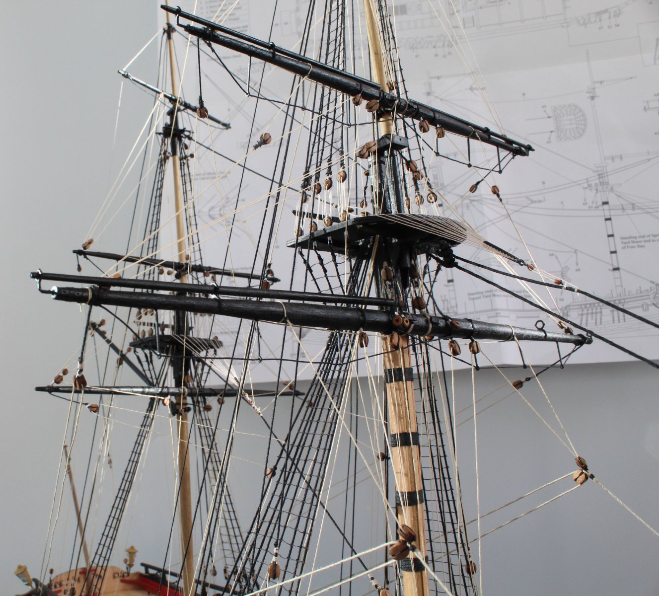
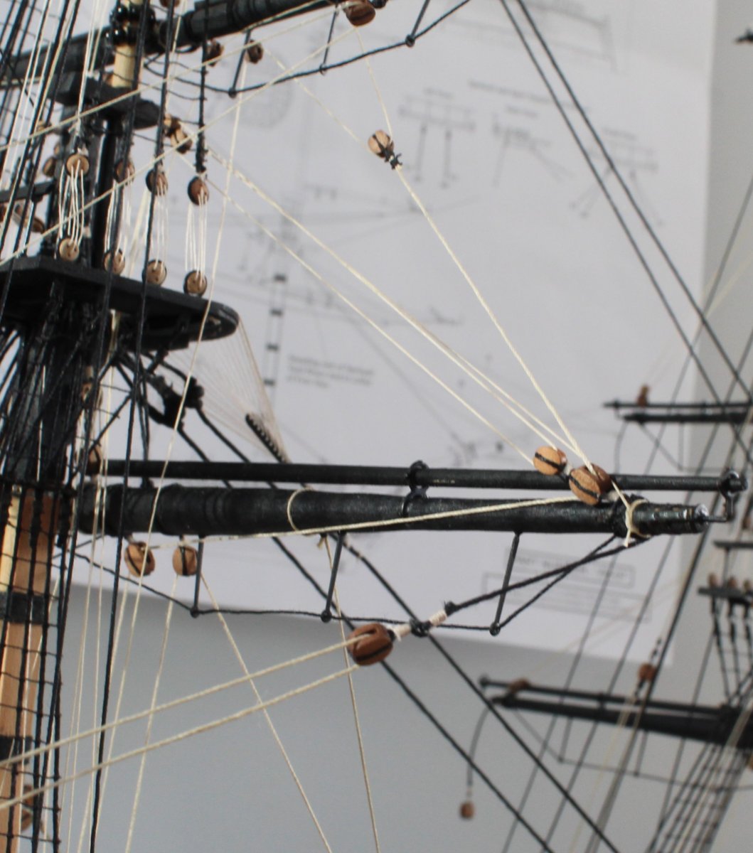
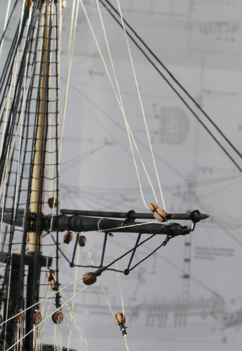
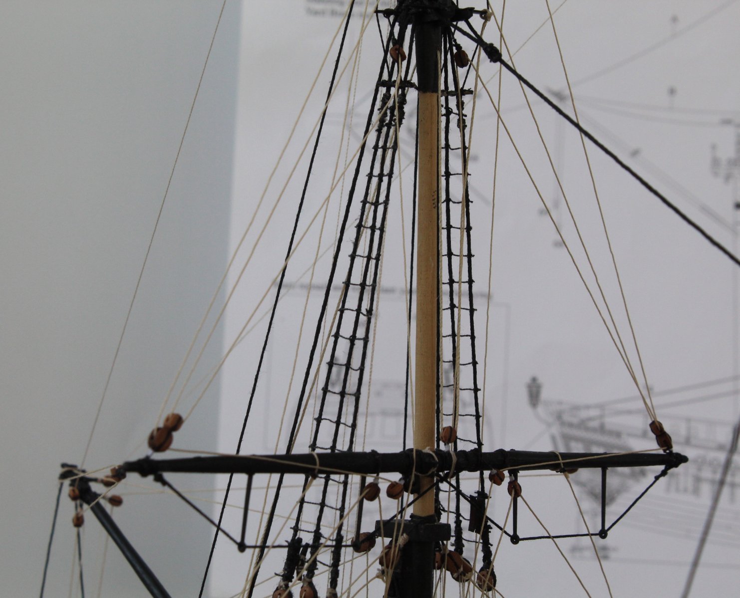
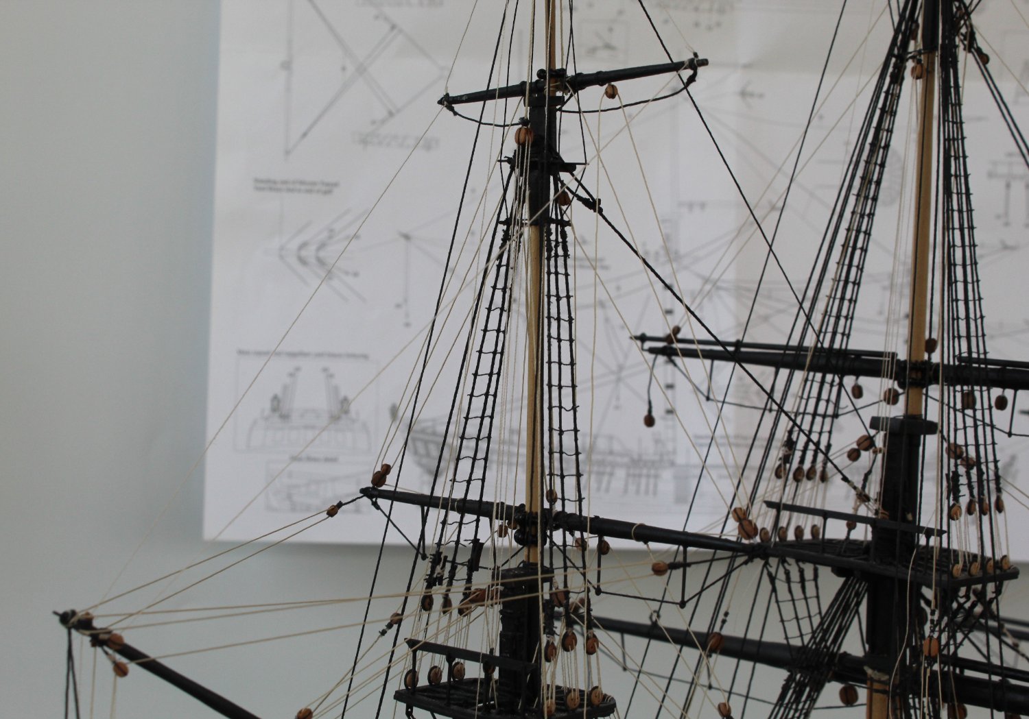
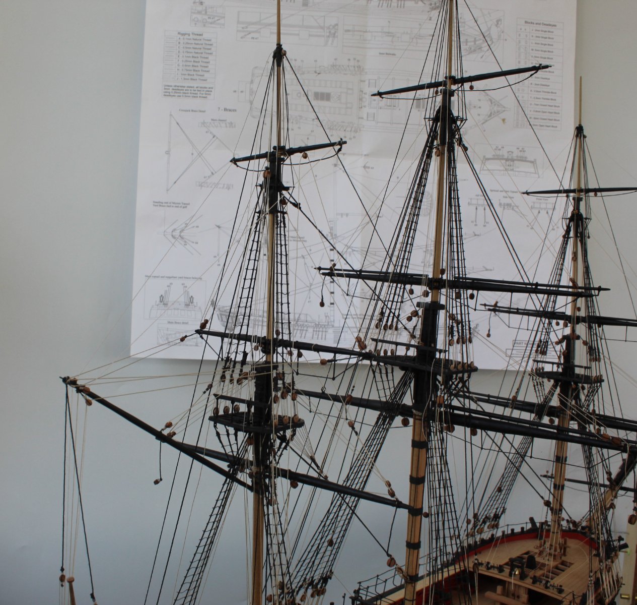
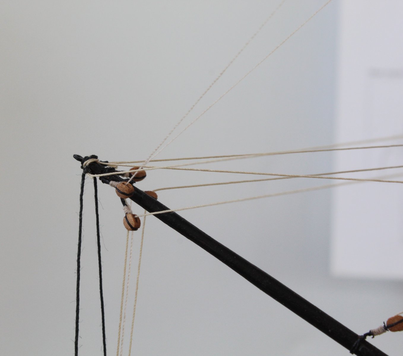
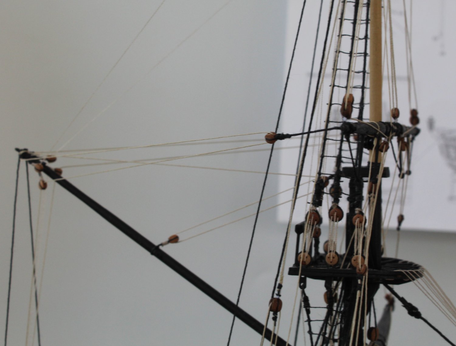
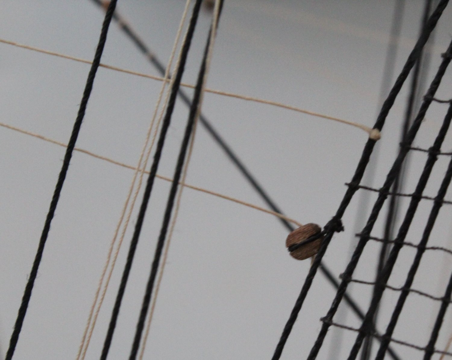
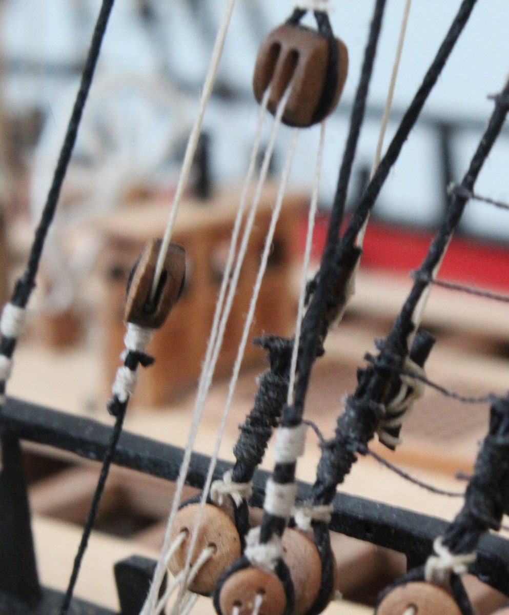
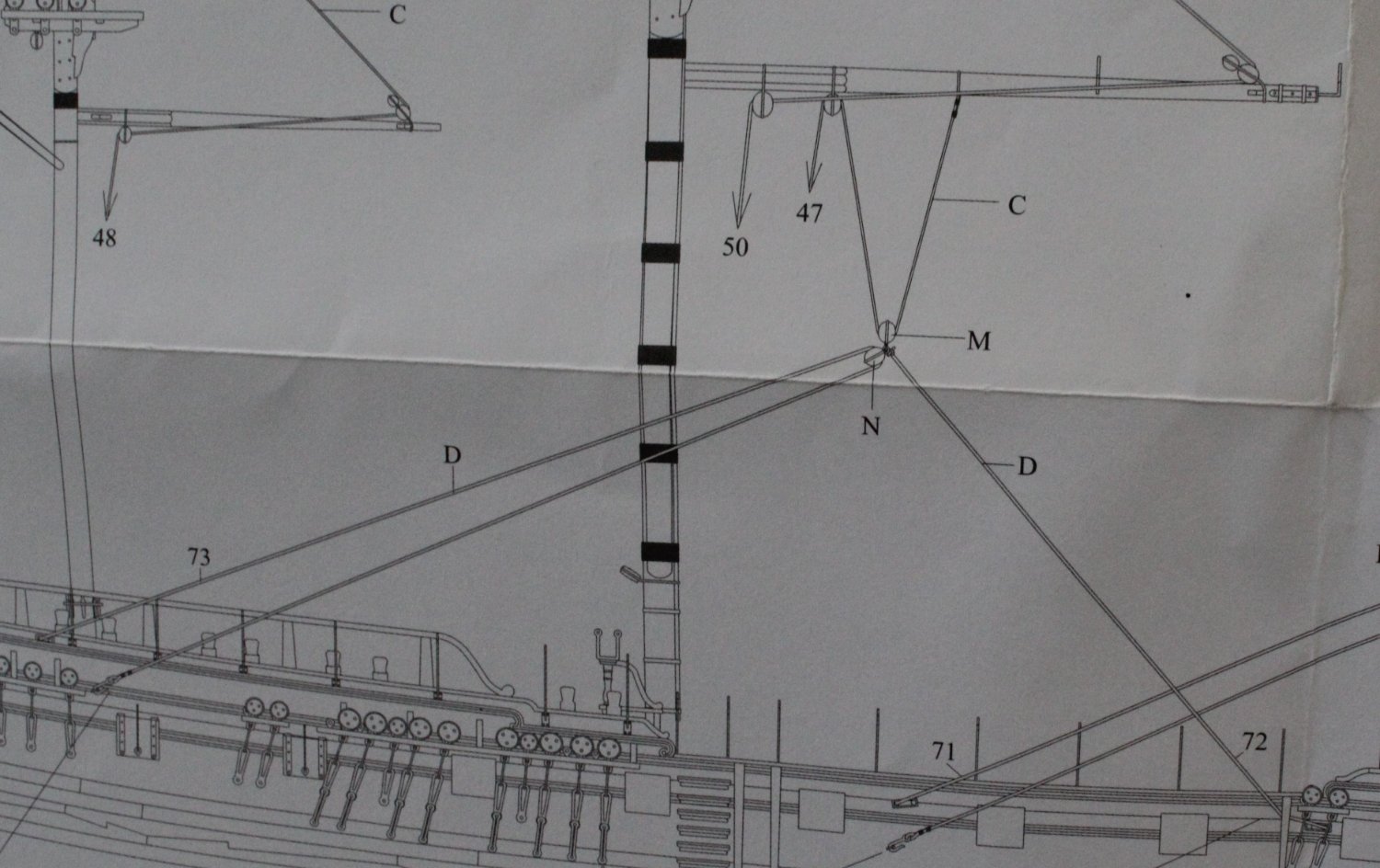
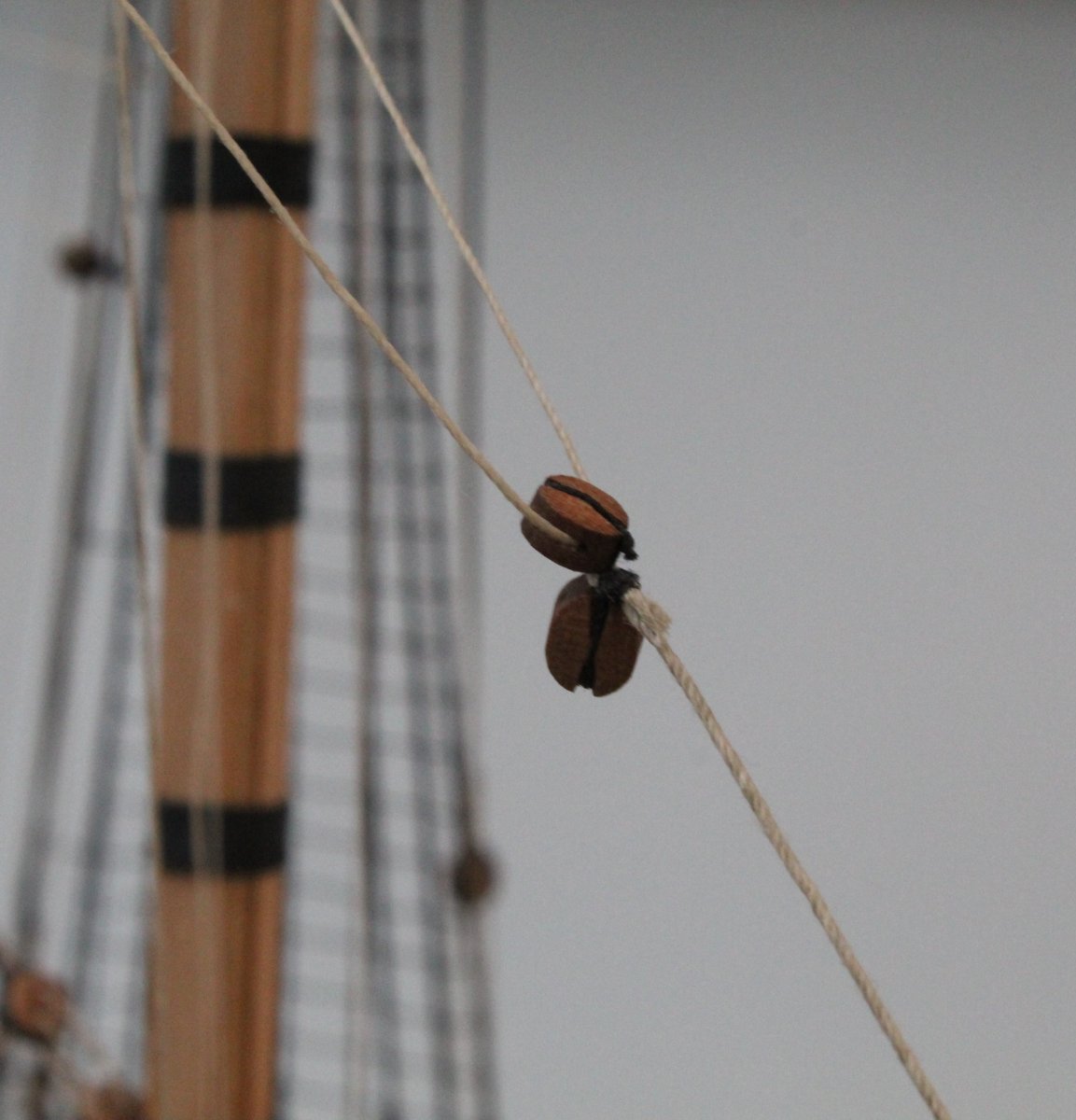
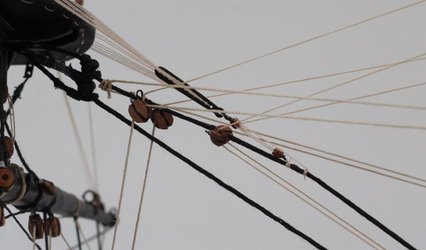
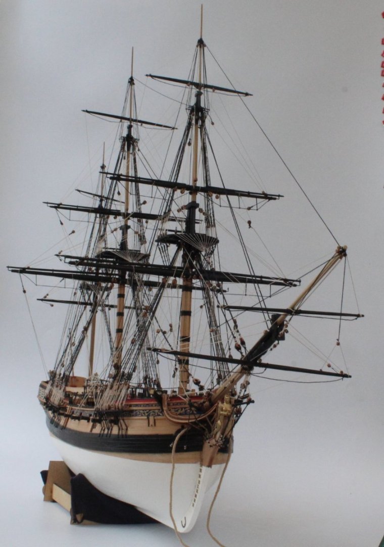
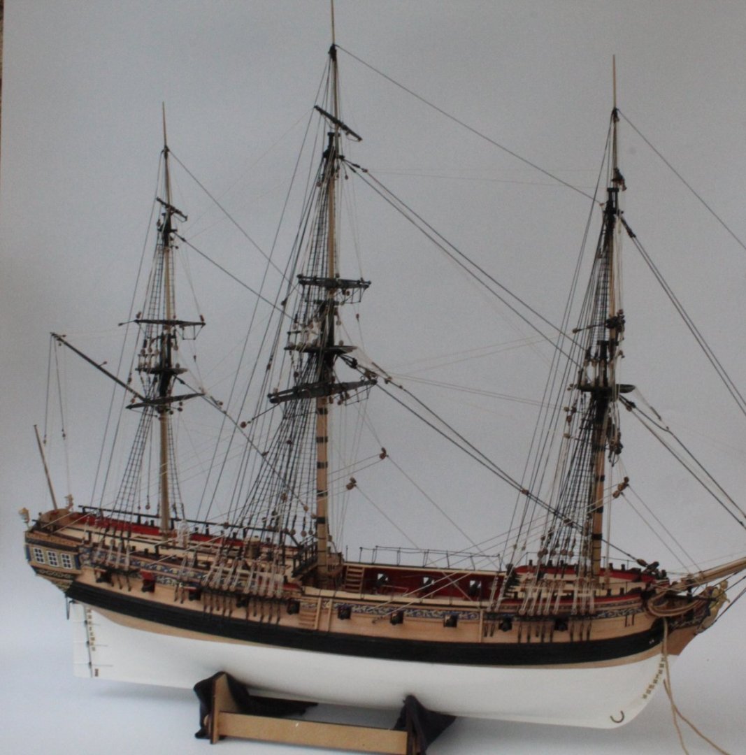
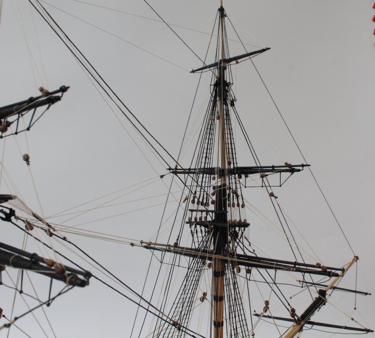
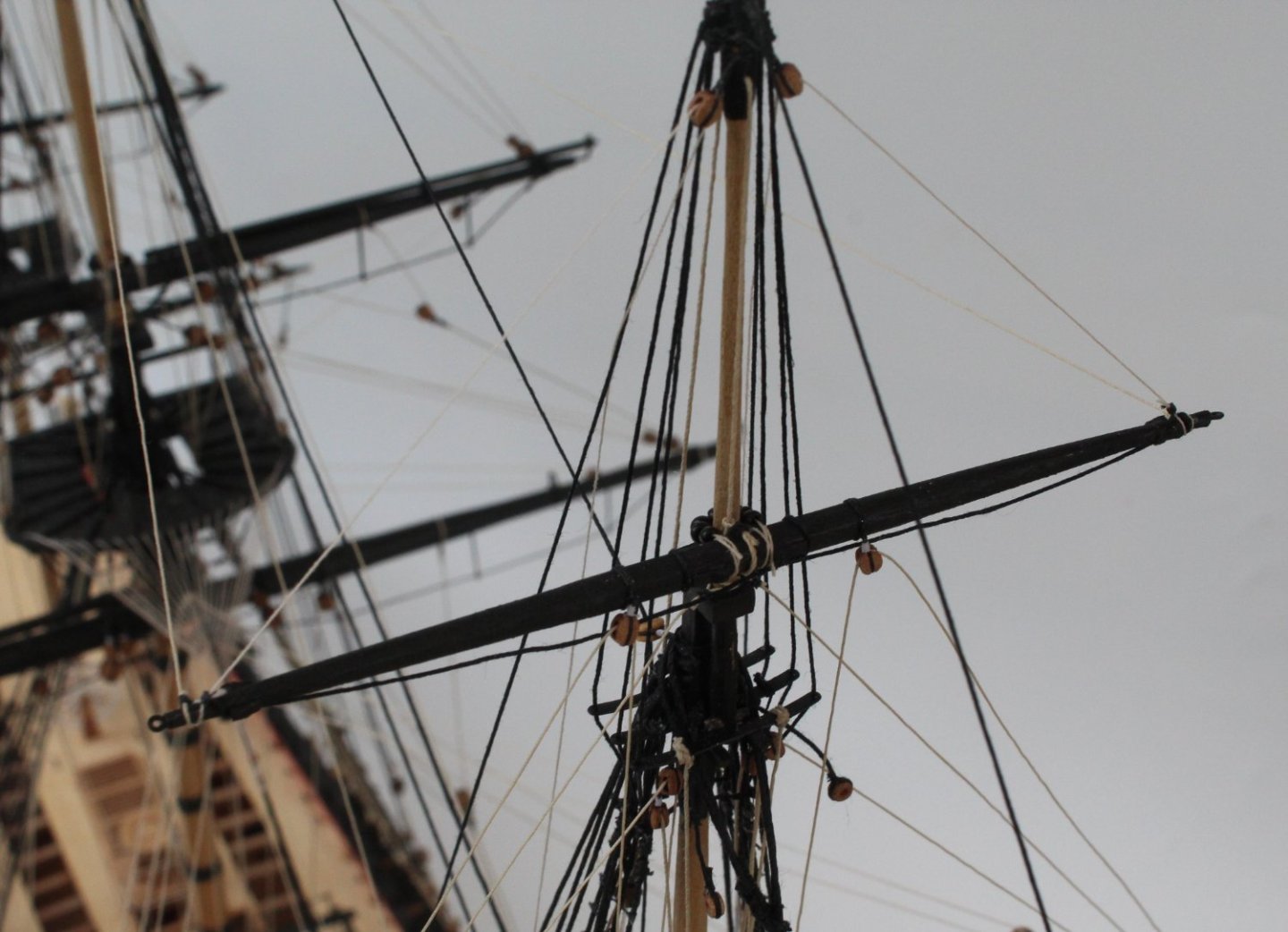
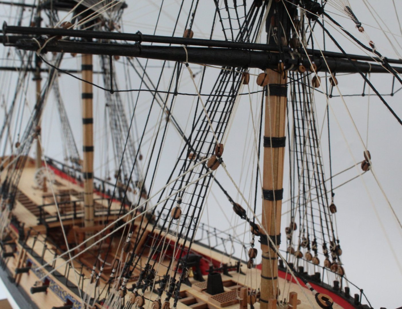
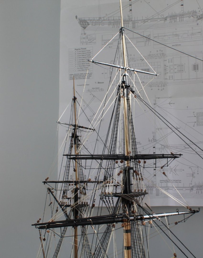
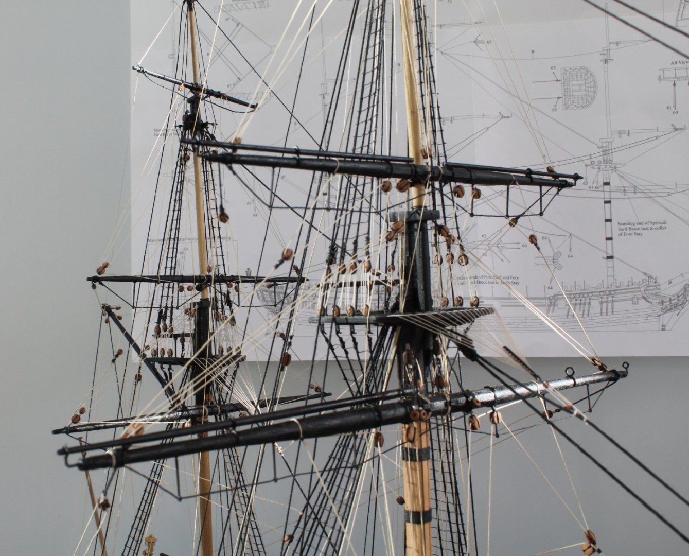
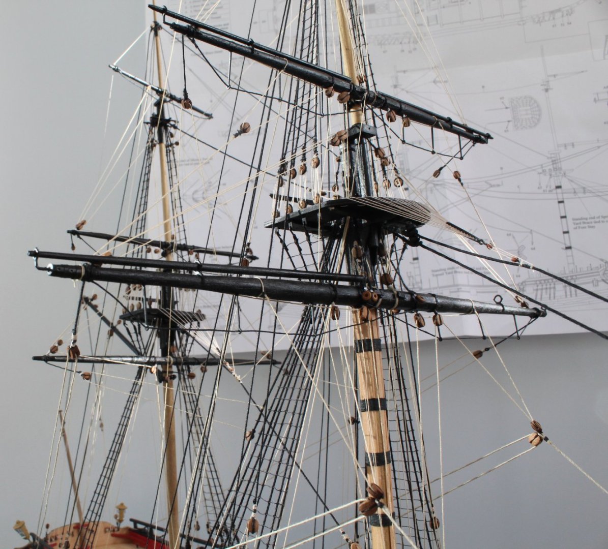
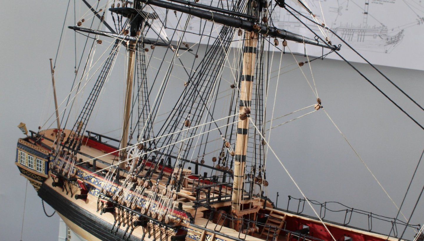
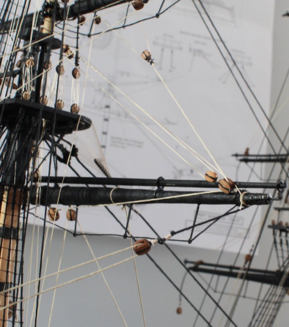
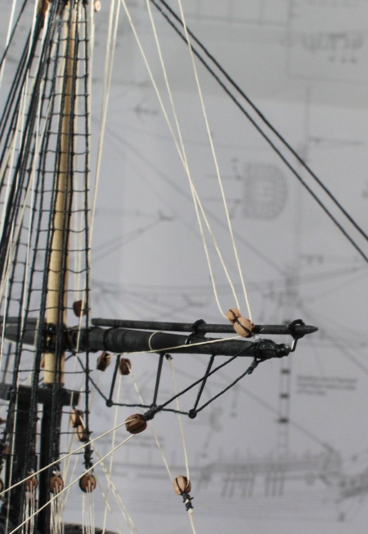
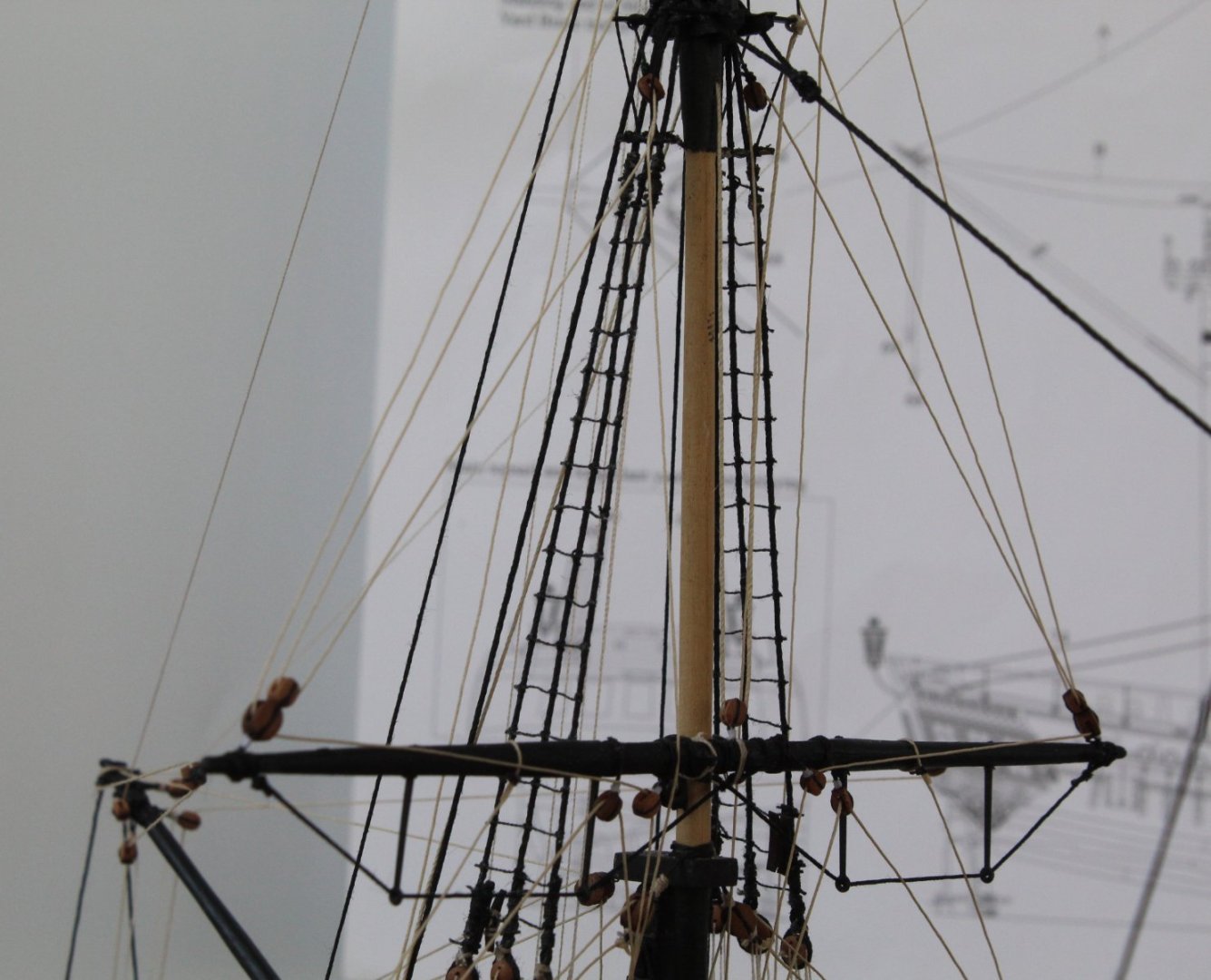
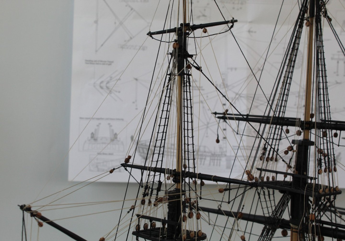
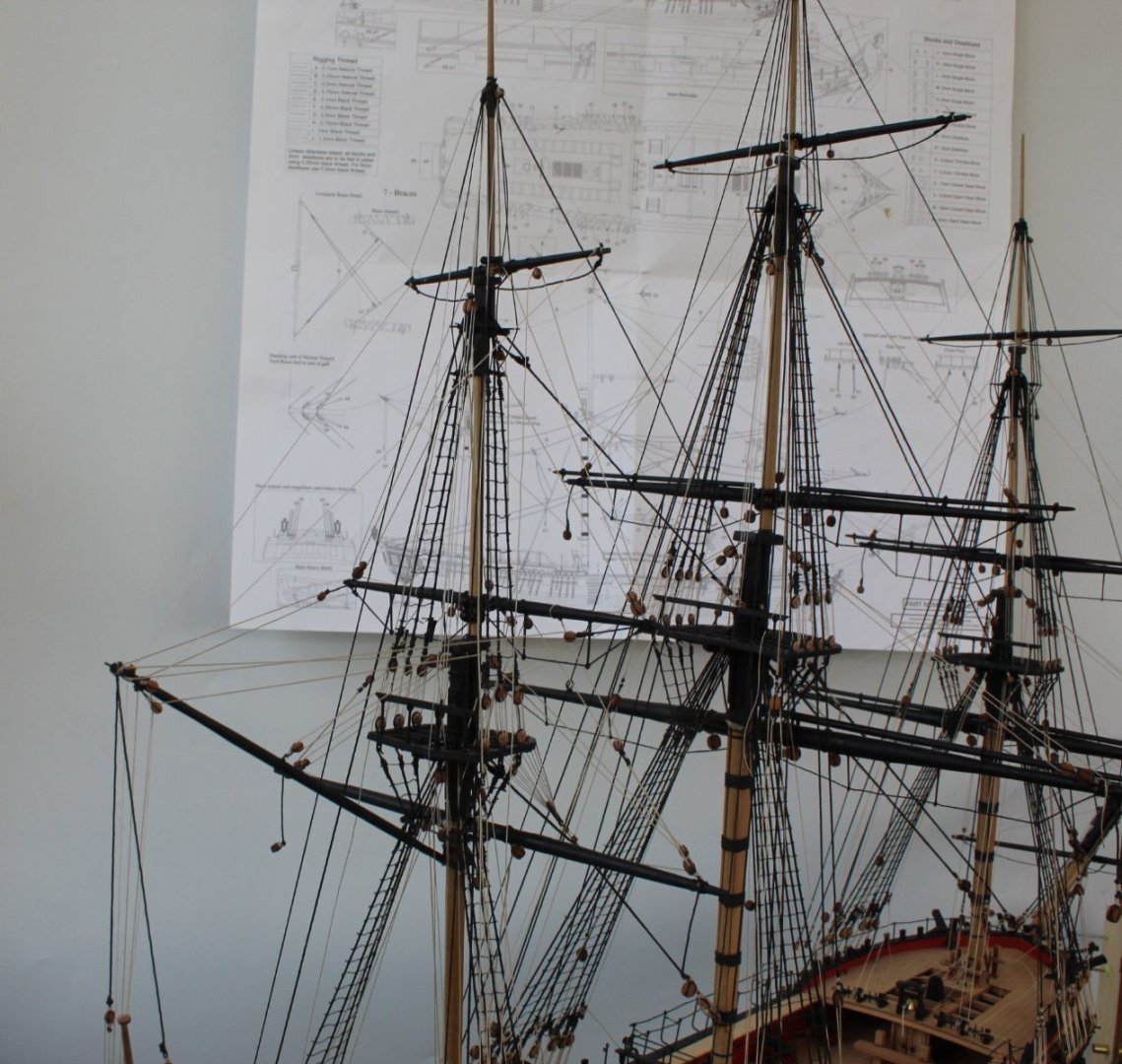
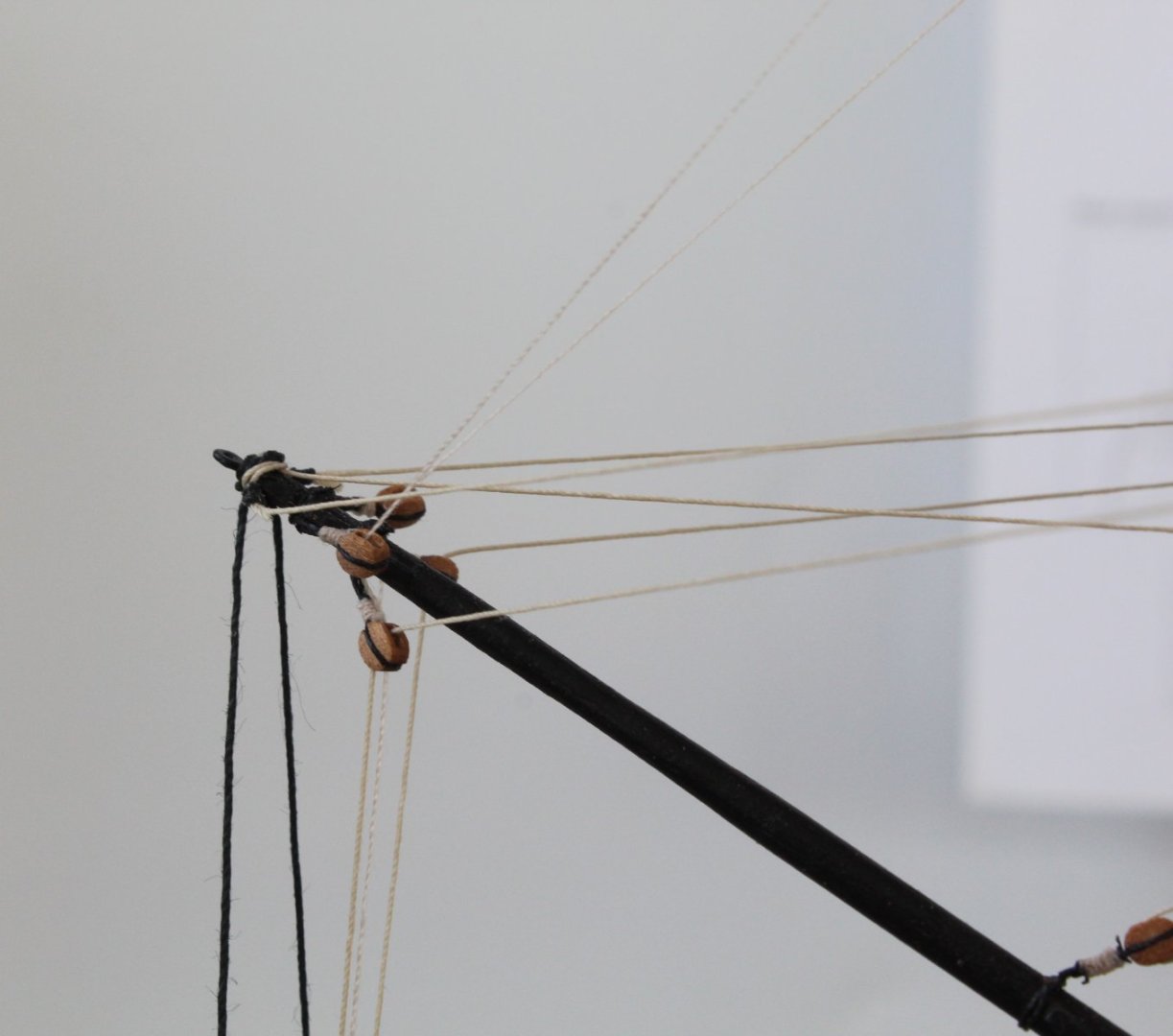
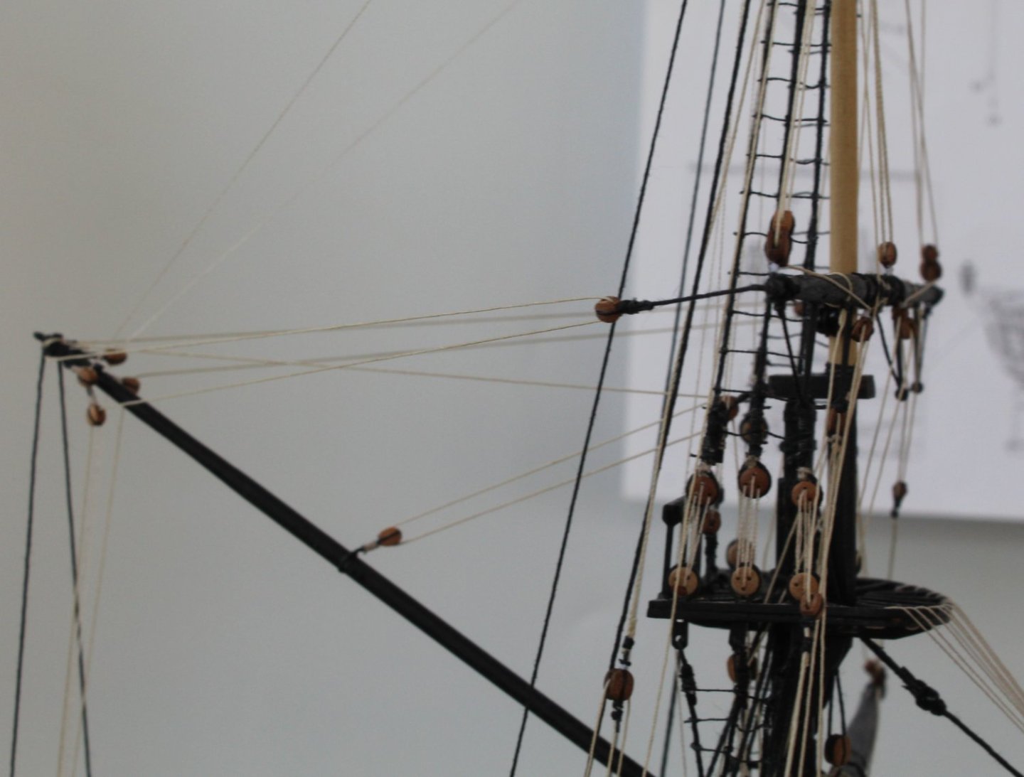
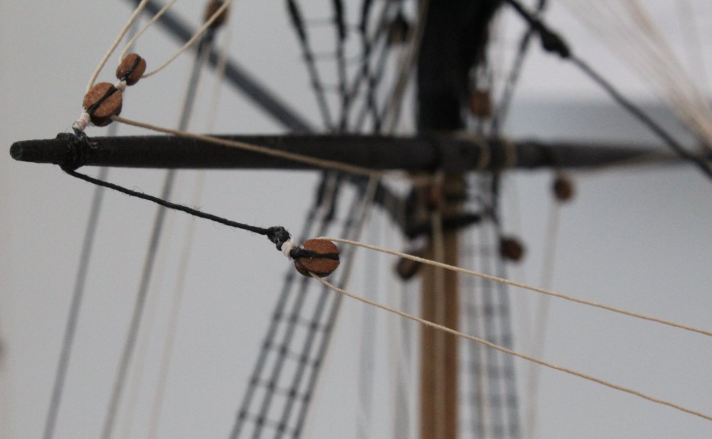
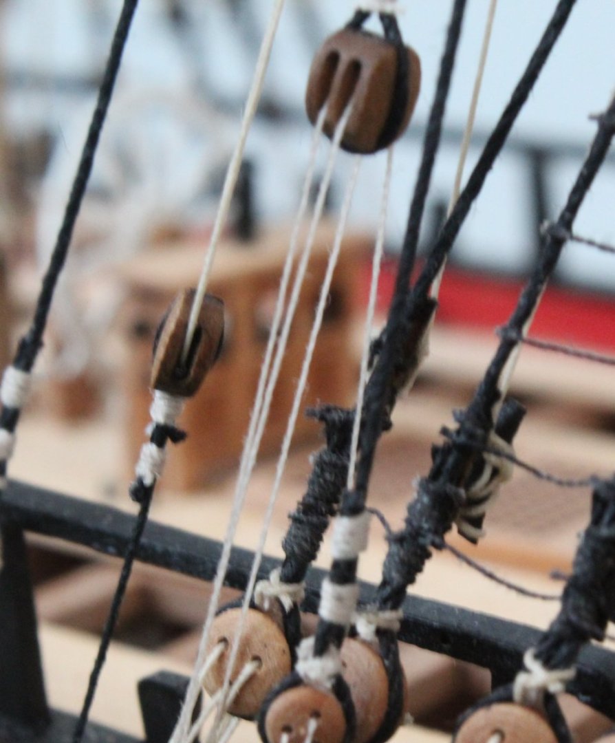
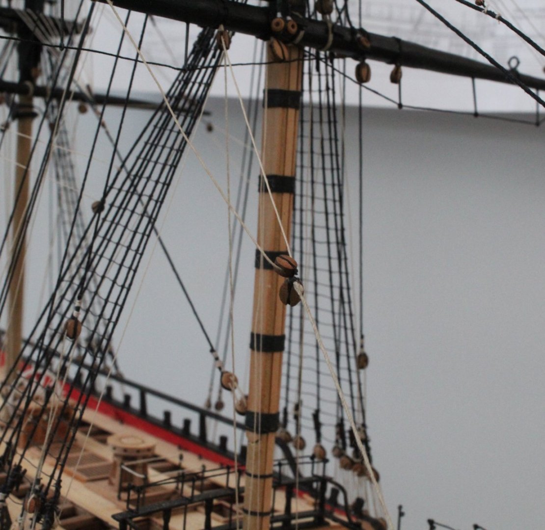
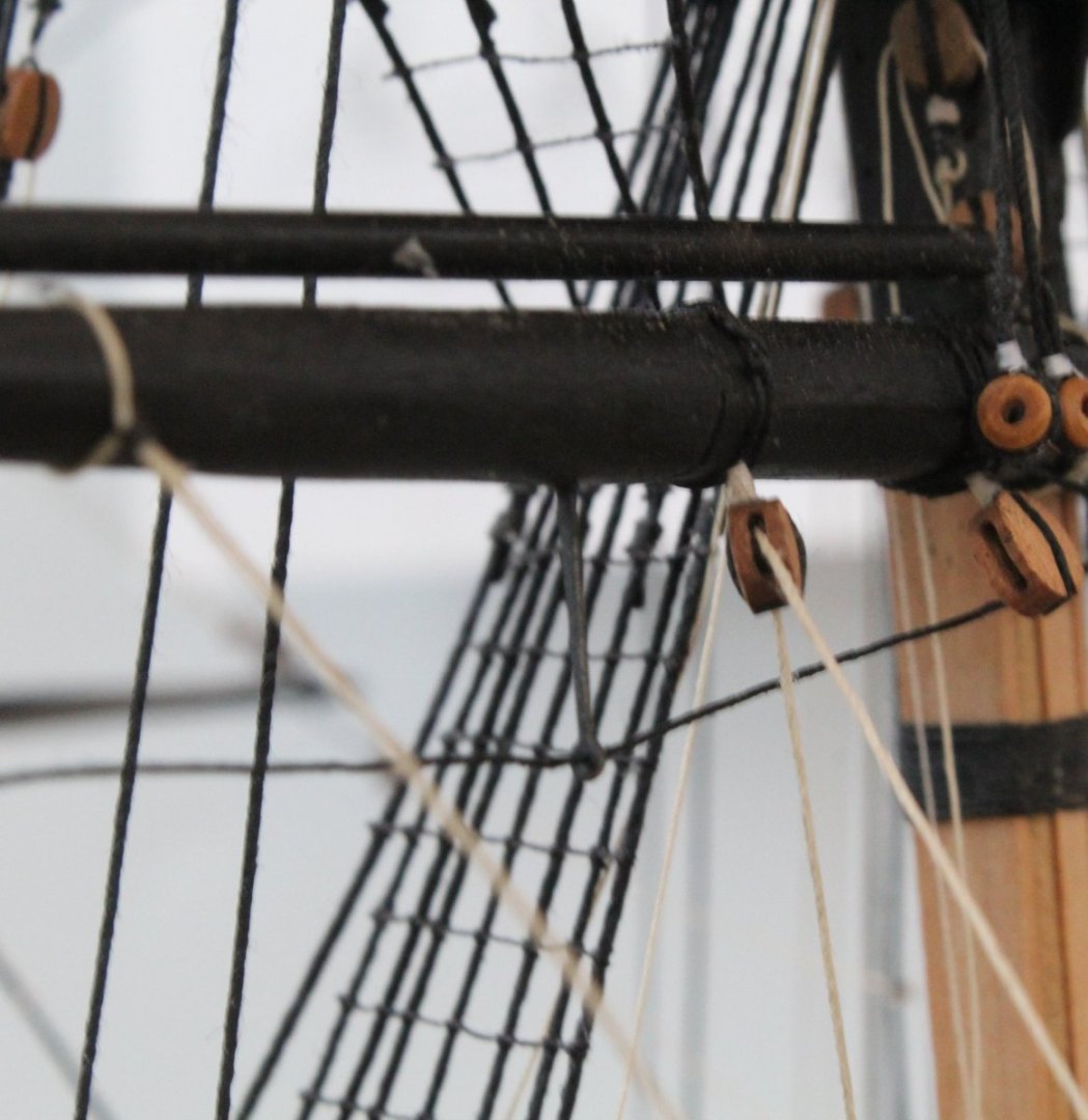
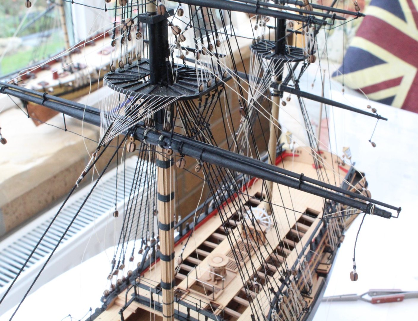
Rigging Completed I have now added the sheet, tack and braces to the 3 off fore yards. This now means I have completed the rigging phase of the build. The only task left is to build and fit the anchors. As mentioned in a previous post I am not planning to build and fit the 3 small boats for the time being. The following 5 photos shows some different aspects of the yard rigging for the foremast yards. The following photo shows the foreyard and fore topsail yard brace rigging as it passes through the various blocks on the main mast stay The final few photos


- 476 replies
-
- 23
-
-

-
- sphinx
- vanguard models
- (and 1 more)
-
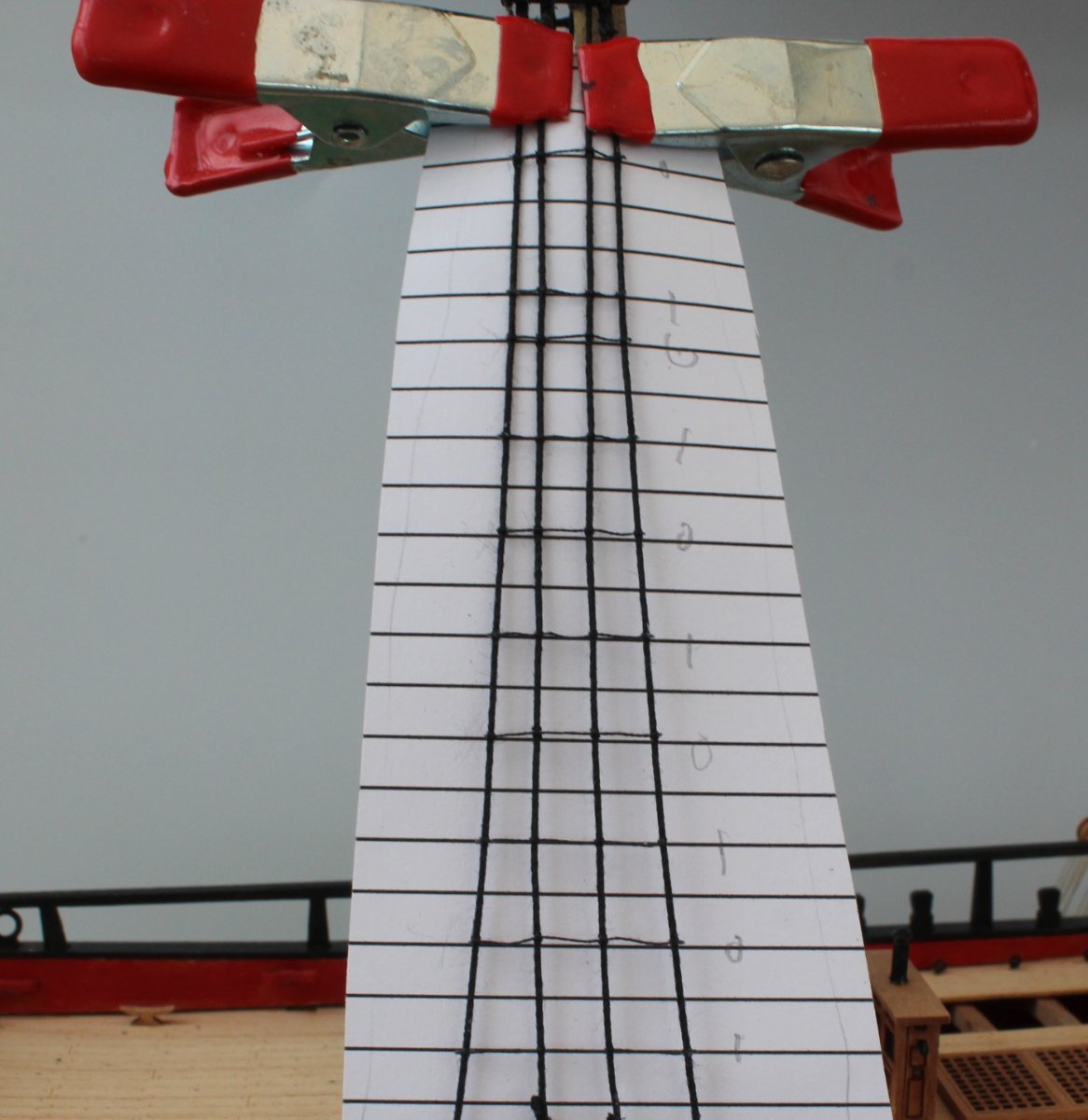
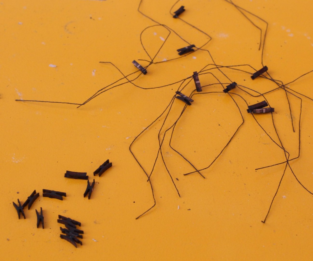
Nice work. When adding ratlines I have found it better to work from bottom and to add every 5th one first (The 0's in attached photo). Then I add the middle ratlines between every 5th one (the 1's in the attached photo). Finally I add in ratlines in the gaps.

- 59 replies
-
- 3
-
-
- saucy jack
- fishing smack
- (and 2 more)
-
This is a great kit and I'm sure you will enjoy the build.
-
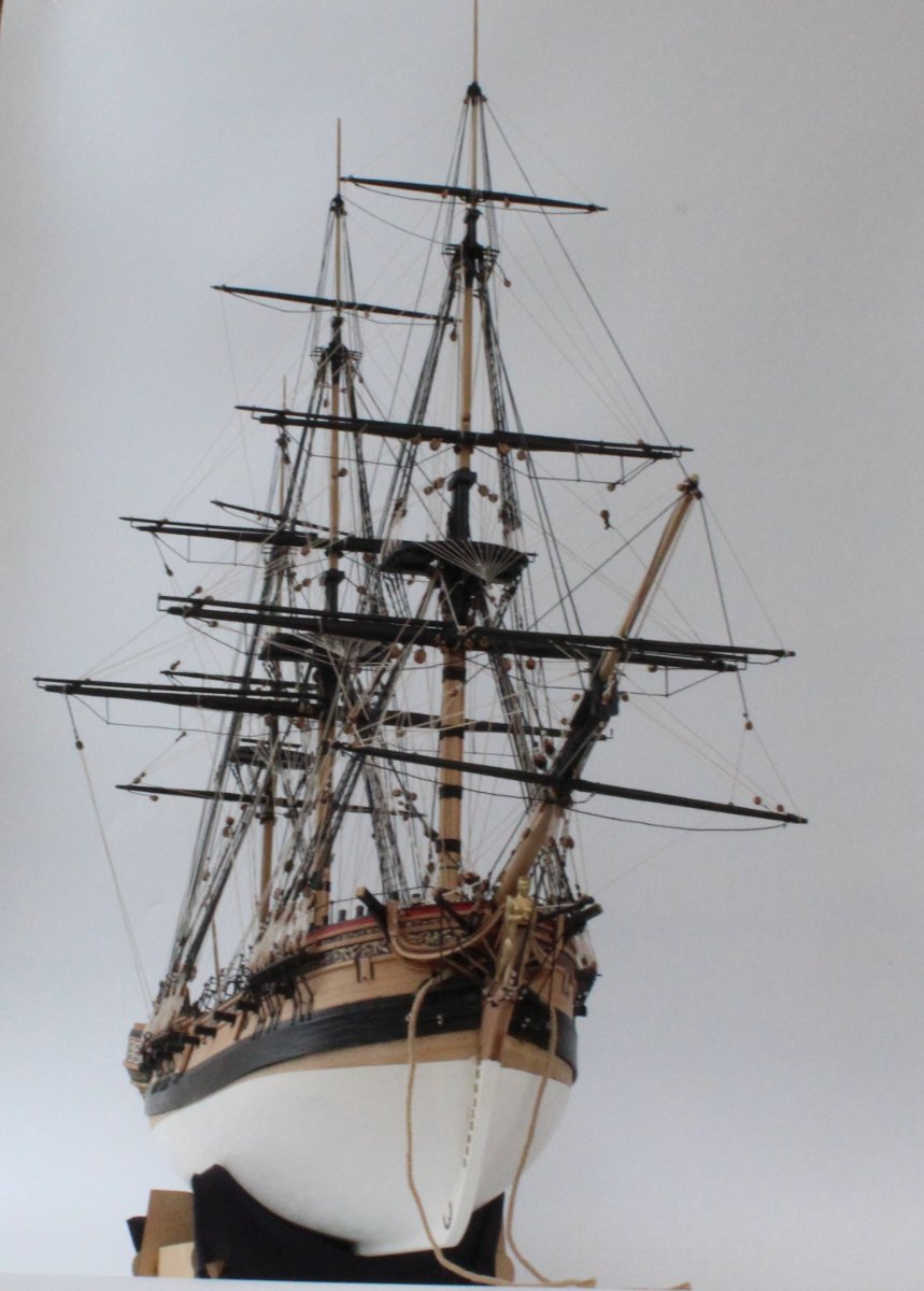
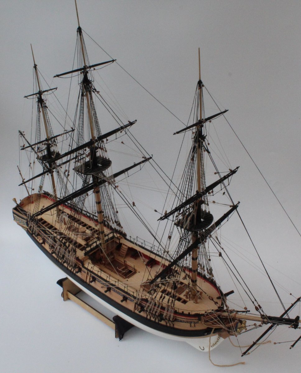
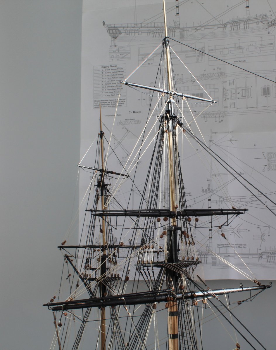
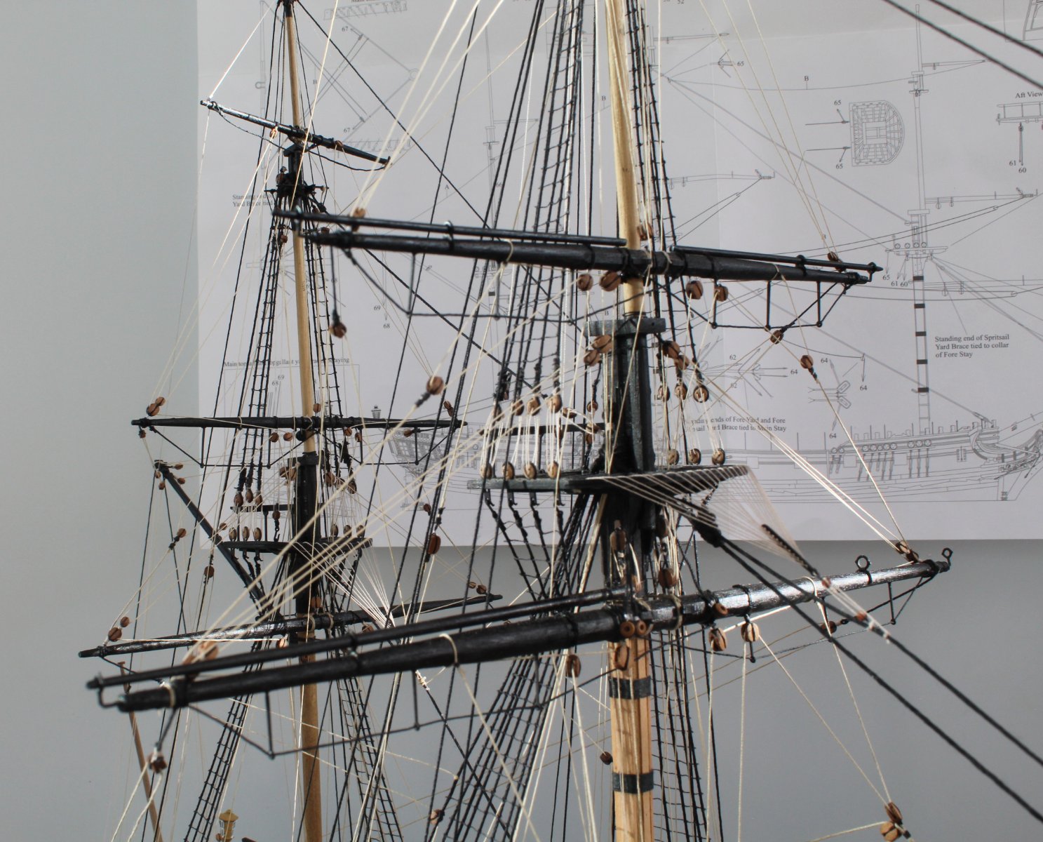
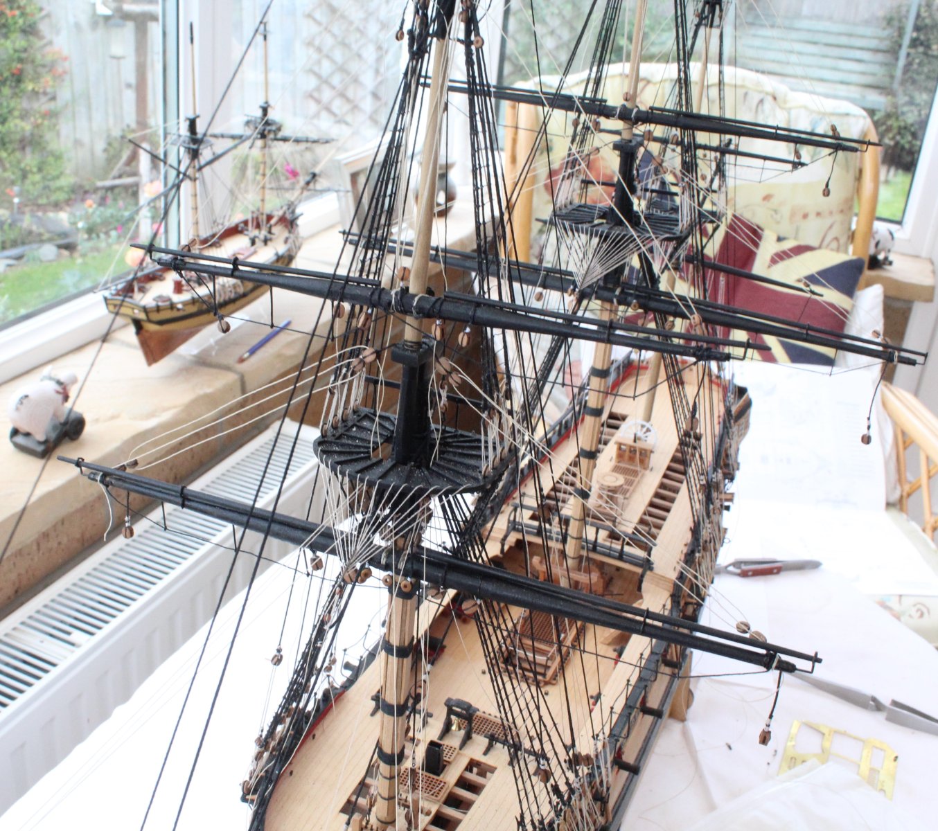
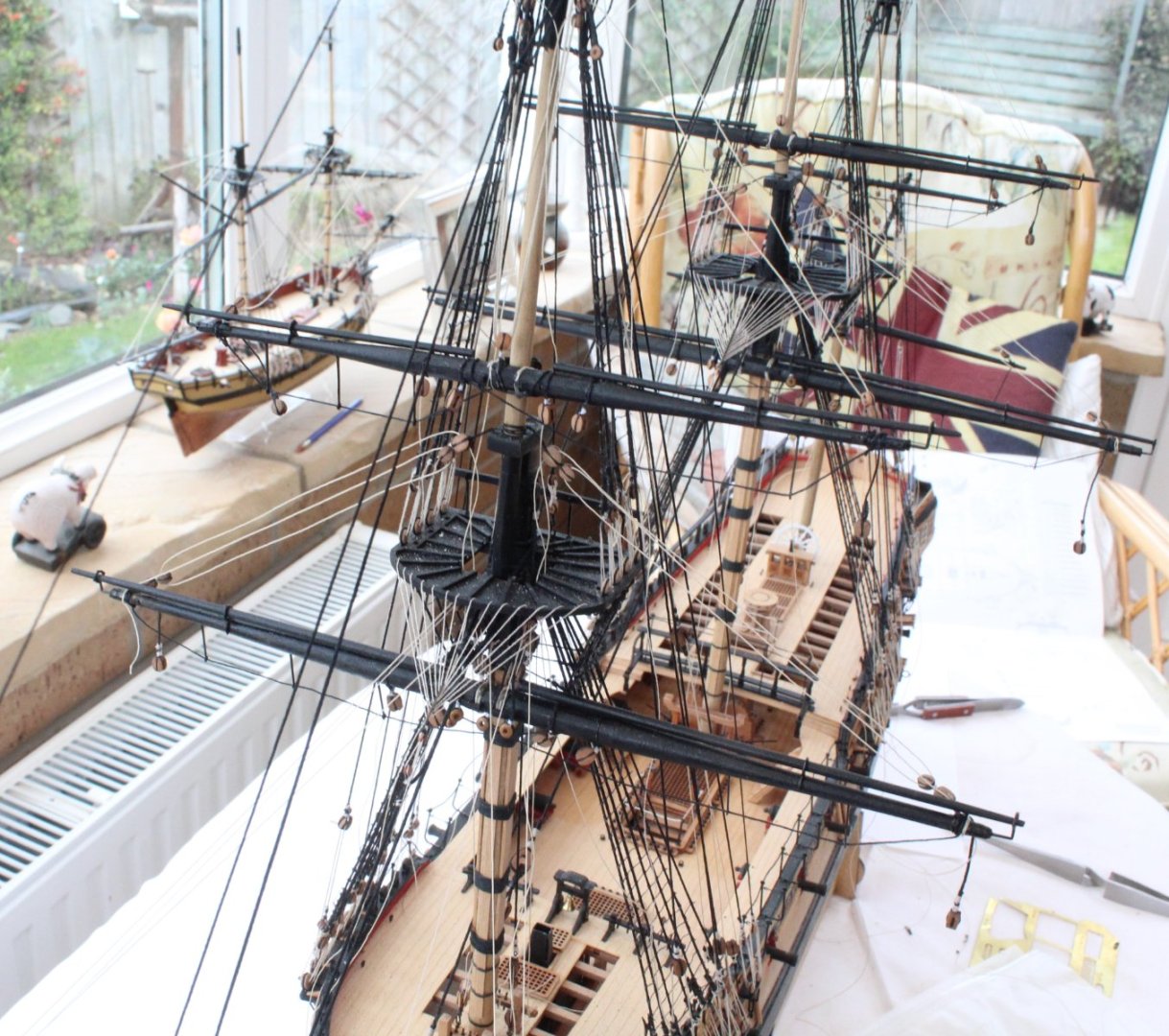
Main, Topsail and Topgallant Yard Rigging Completed I have now added the sheets, tacks and braces to the main, topsail and topgallant yards. For the most part I am happy with the end result, however when taking some photos I noted one slight error, which can be seen in below. This error can be corrected if I remove and rerun the rigging line. I have lost count have how many times I have already rerun some of the rigging threads to avoid tangles and crossed threads therefore it will stay as is for the time being. I am not best pleased with myself for missing this one. I have not been able to master the art of tensioning and securing the rigging thread free ends to their respective belaying pins and cleats as it should be done. The thread tends to unwrap itself as I try to manoeuvre it around the pins / cleats. More often than not I have to resort to using small amounts of ca to hold the thread in place during the belaying process. Here are some photos showing the current build status. I found it very difficult to take decent photos. The next task will be to rig the fore, topsail and topgallant yard sheets, tacks and braces. Once that is done the anchors will be added which will be the final build task for this build.

- 476 replies
-
- 10
-
-
- sphinx
- vanguard models
- (and 1 more)
-
Looks like you've made a good job of the shrouds.
-
A great build so far.
-
You certainly have the skills to build the Alert
-
Nice work. Looking at the deadeyes I assume they are free to rotate so they are correctly aligned when adding the lanyards.
- 88 replies
-
- 1
-
-
- Erycina
- Vanguard Models
- (and 2 more)
-
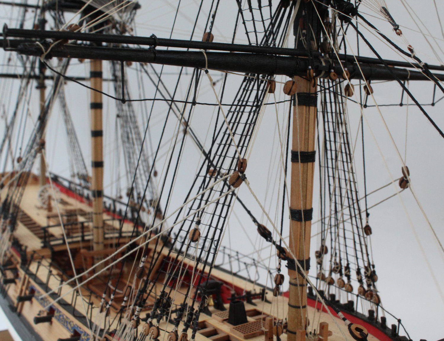
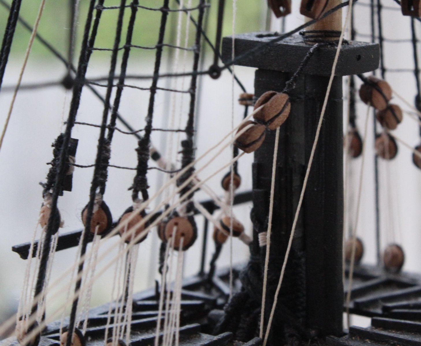
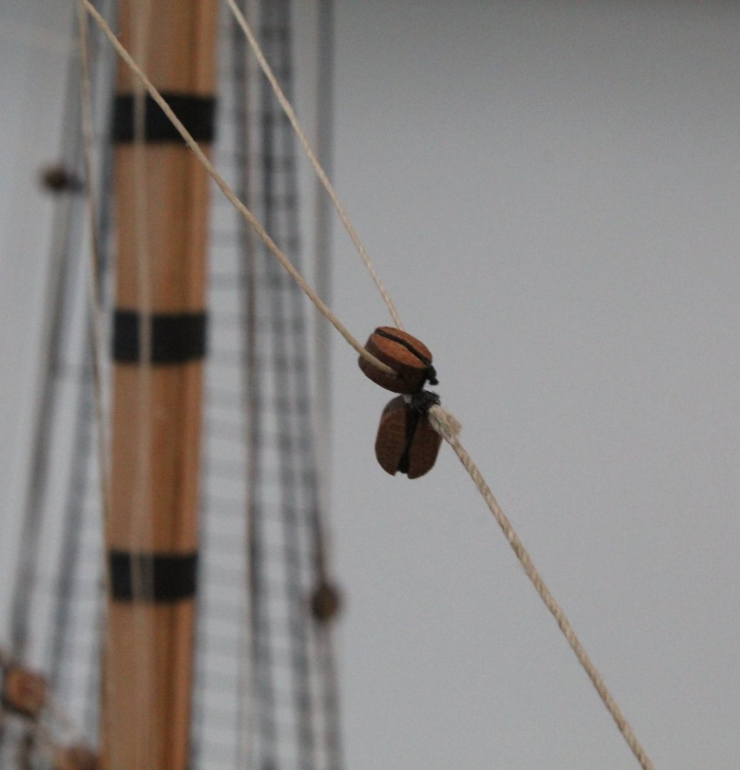
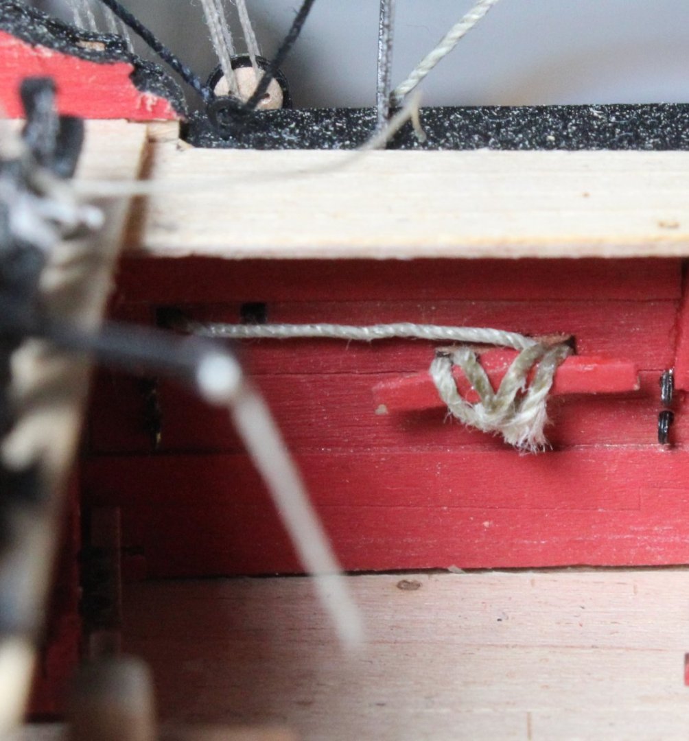
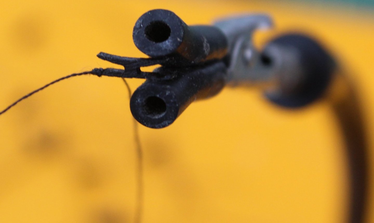
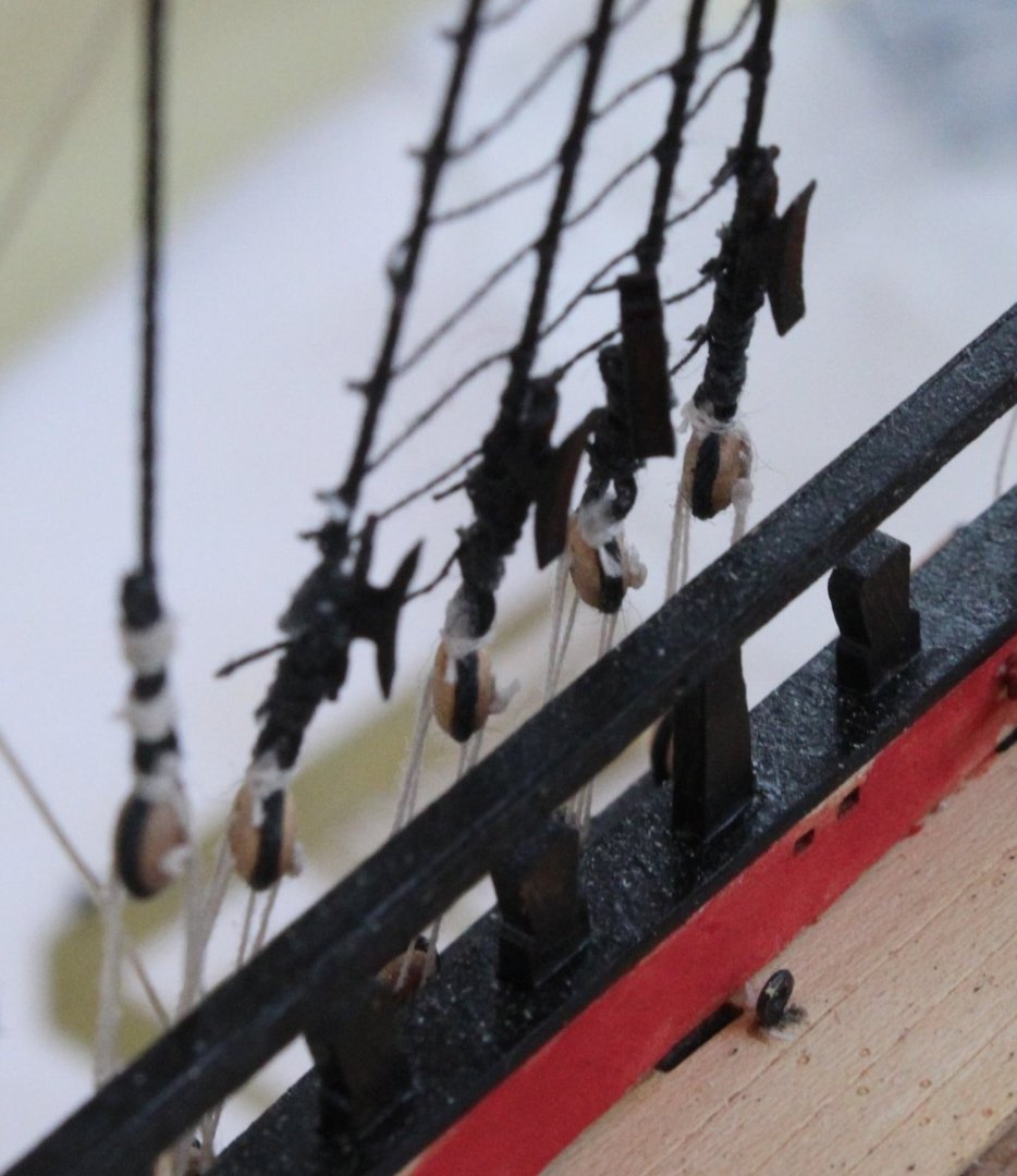
Mizzen Mast Rigging Completed After belaying the mizzen mast sheets and tacks rigging, I decided to add the mizzen yard braces. The first two photos show both the topsail and topgallant yard braces as they pass through the final blocks located on the end of the mizzen gaff. The crossjack yard brace threads are secured to the rear most main mast shrouds and are then fed through the yard brace blocks. The threads are then fed through blocks located on the same shroud lines. The starboard shroud line, with the brace rigging, is shown in the next photo The next photo shows the crossjack brace with the thread rigged. The crossjack braces rigging is then belayed to cleats located on the back of the main mast shroud line, as shown below. I have added a few photos of the completed mizzen mast rigging. Main Mast Sheets and Tacks - WIP With the completion of the mizzen mast and yard rigging I moved on to the main mast sheets and tacks. As can be seen in the picture below the main yard rigging is quite involved. I did cover the preparation of the blocks for this task in a previous post. The next photo shows the start of the rigging with the thread (blurry) seized around the main yard. The thread can also be seen passing through the yard block also. The next photo shows the upper part this rigging. Now a close up of the double block. The thread from the center of the double block is fed through a hole in the hole and then belayed to a cleat on the inner bulwark. Not brilliant belaying but the thread is secure. There is still a little bit more rigging to add to complete this task.

- 476 replies
-
- 5
-
-
- sphinx
- vanguard models
- (and 1 more)
-
The ones I have just bought are ideal for belaying in my opinion.
- 476 replies
-
- 2
-
-
- sphinx
- vanguard models
- (and 1 more)
-
New Tool Alert When rigging on all my previous build and on my current Sphinx I have always had found it troublesome to secure the free ends to the belaying pins and / or cleats. I have a great pair of small straight reverse action tweezers which has been my main tool, but they are not ideal. I also have a nice pair of right-angle tweezers (normal action). However, I find it difficult to retain hold of the thread as these tweezers are not reverse action. In the past I have looked and ordered a pair of reverse action right-angled tweezers, but they were much too big for belaying free ends. Yesterday afternoon I took delivery of some small craft tweezers, reverse grip tweezers. Today, when I started to belay the mizzen sheets and tacks free ends to the shroud cleats, I used the new tweezers. I am happy to report that the belaying task suddenly became so much easier and I wish I had discovered these tools many years ago. I have added a hyperlink to these tweezers below. Craft Tweezers Crossing Lock Soft Gripping Tweezers Reverse Grip
- 476 replies
-
- 7
-
-

-
- sphinx
- vanguard models
- (and 1 more)
-
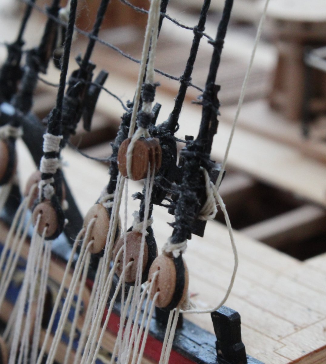
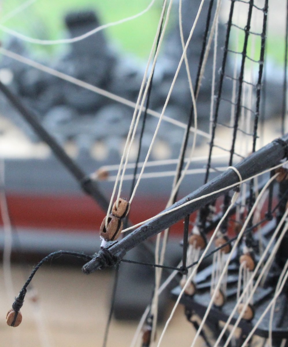
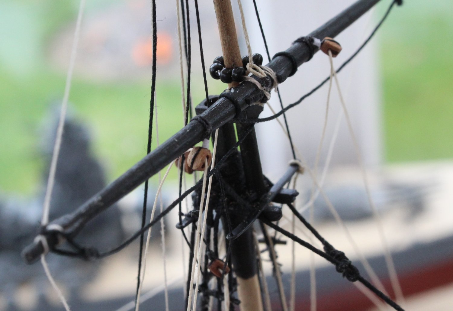
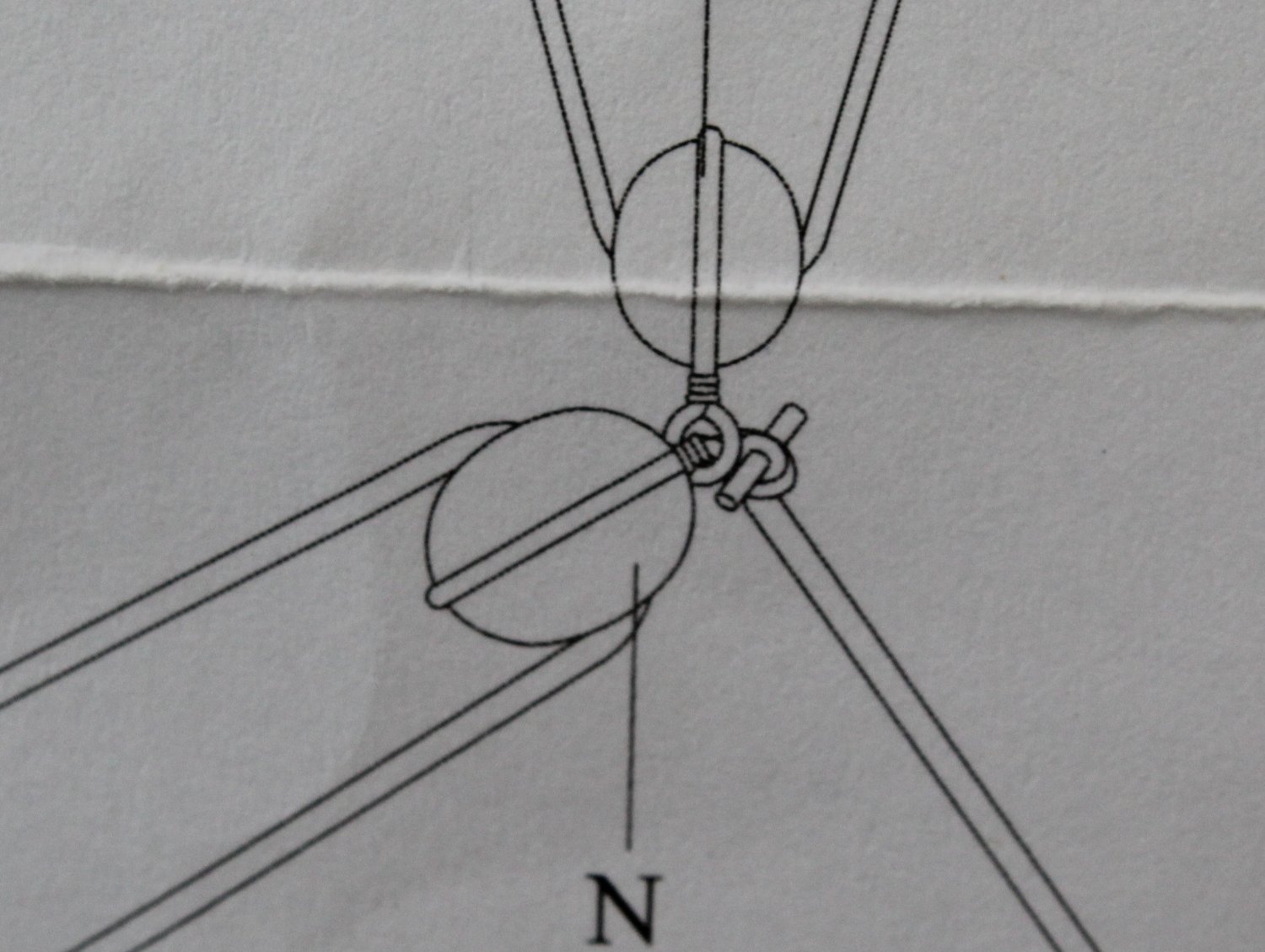
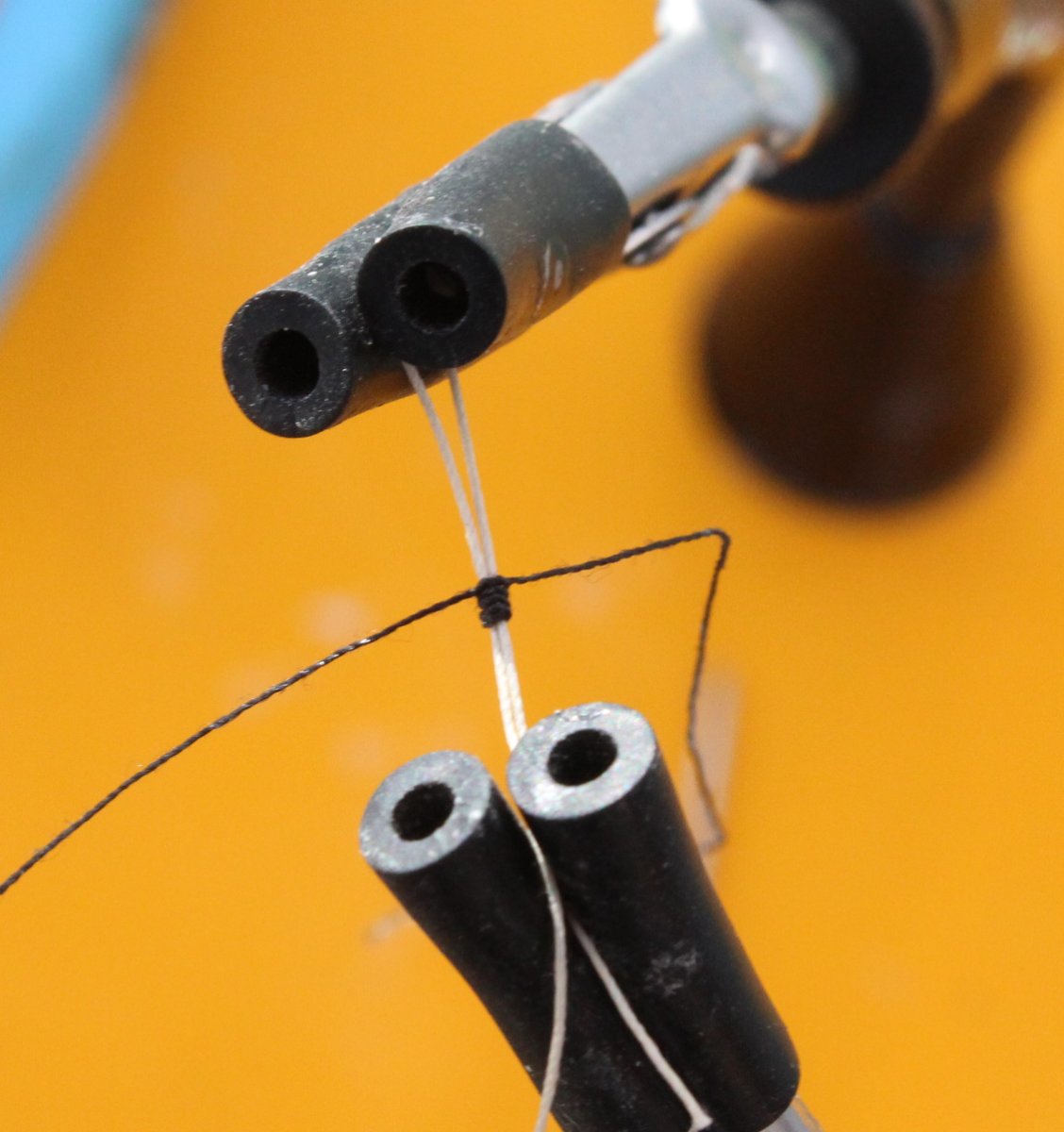
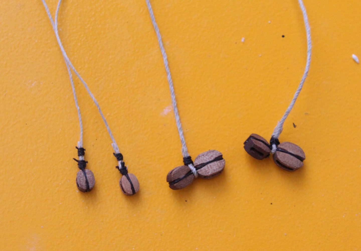
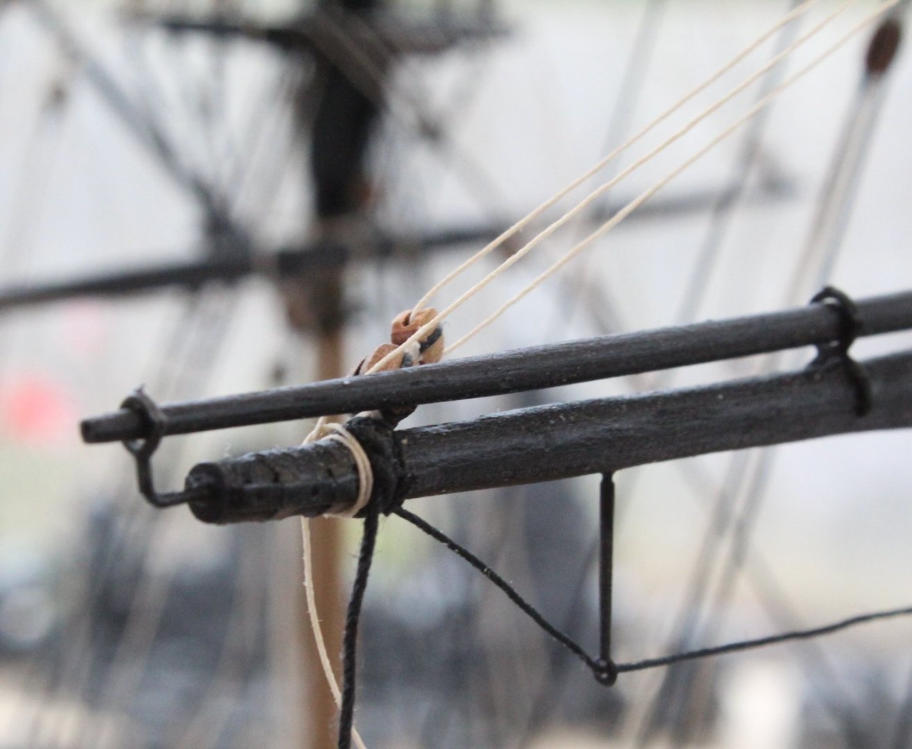
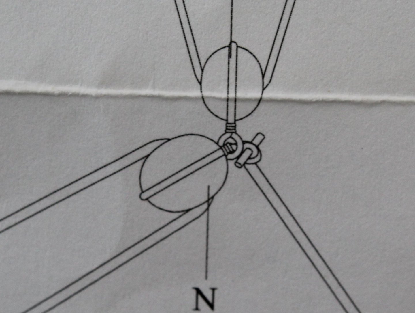
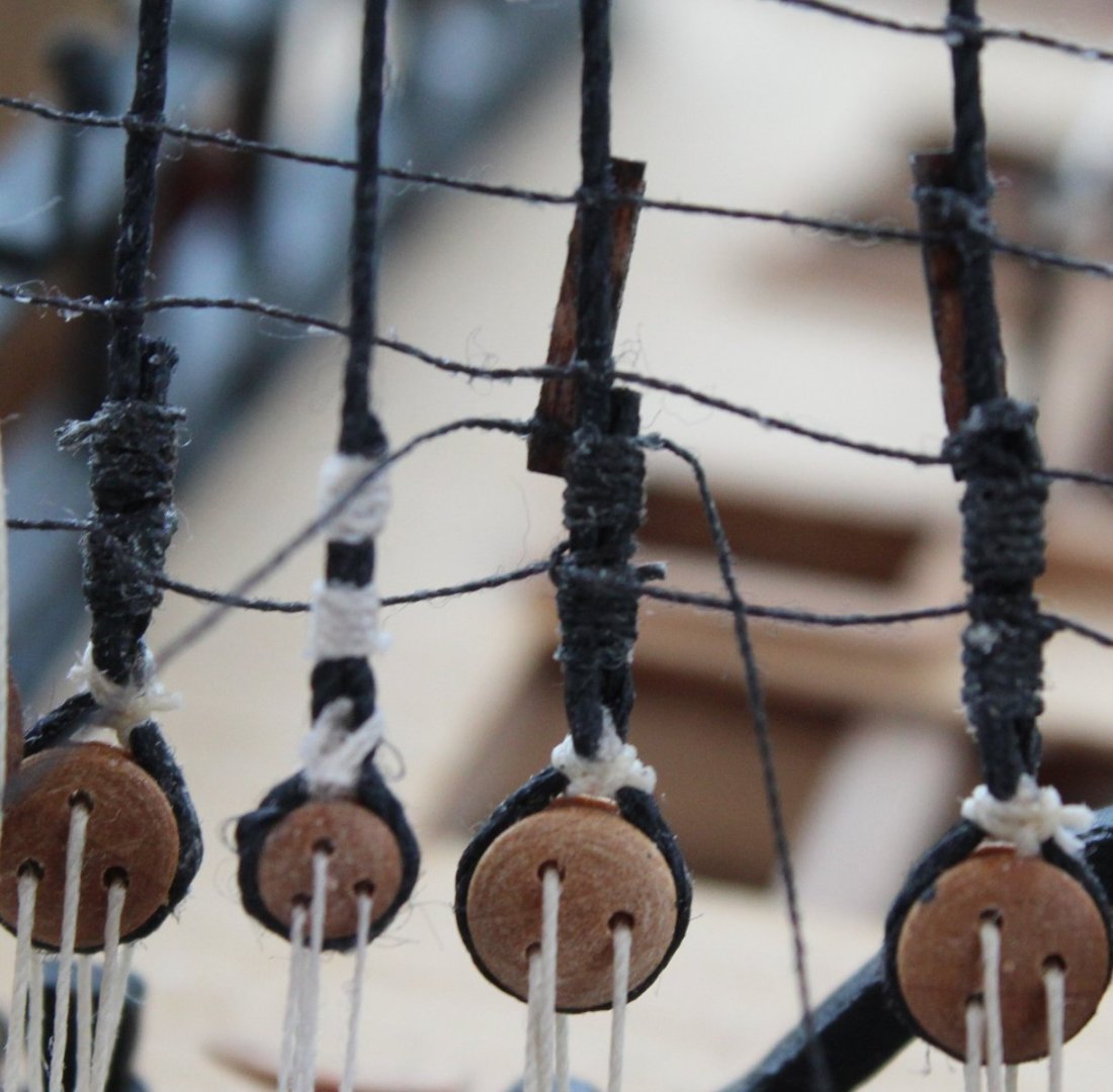
Yard Lifts - Completed Over the last couple of days all the missing shroud cleats were secured in place. With these in place I was then finally able to belay the free ends of the yard lift rigging. It was not the easiest task to complete, some free ends took no time at all to belay whilst some other free ends put up a bit of a battle. I have shown the rigging of one the lifts in the following three photos. This now means that I have completed all the work shown on rigging plan sheets 1, 2 and 3 and will now move on rigging plan sheets 4, which is the last rigging sheet. Sheets and Tacks - Work In Progress Starting with the mizzen mast the rigging for the sheets and tacks has been run in and is now ready to be belayed. The belaying points for the various free ends will be on the mizzen mast shroud cleats. The photo below shows the rigging fed through the larger of the double block arrangement fitted to the end of the yard. Another part of this rigging can be seen where a length of thread has been seized around the yard In the photo below a length of thread has been fed through one of the yard blocks and is ready to be belayed. I need to rerun this rigging before it is belayed so it sits behind the footrope rather than either side of it. The sheets and tacks for the main (and fore) mast is a bit more complicated in terms of the blocking and belaying requirements. I have noted the requirement for tack toggles which, on the real ship rigging, is a quick release mechanism. As can be seen in the picture below the rigging between the double block can be quickly released when the bar is removed. @chris watton did provide an excellent detailed method on how to replicate the tack toggles in his rigging plans and is a credit to his attention to detail. For example, with reference to the previous picture in this post I should have added a tack toggle between the double blocks. I opted to add the thread with a simple seized loop as can be seen in the shown in the photo below which shows the additional blocks required for the main mast. I think it will take a keen eye (once rigged) to know the toggle tacks have not been fitted on my model. Having said that I think I need a bit more space between the double blocks so after my morning tea-break I will try adding the tack toggle arrangement for the double blocks.


- 476 replies
-
- 10
-
-
- sphinx
- vanguard models
- (and 1 more)
-
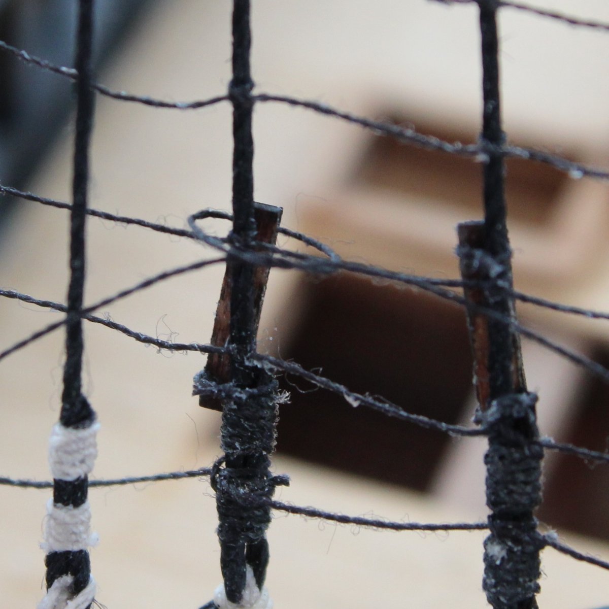
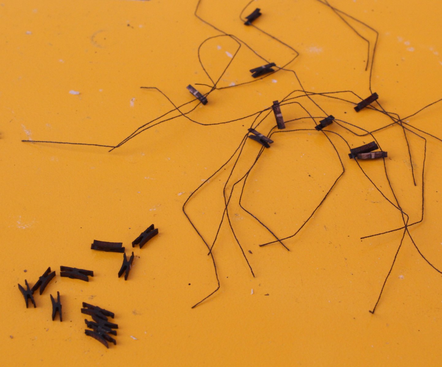
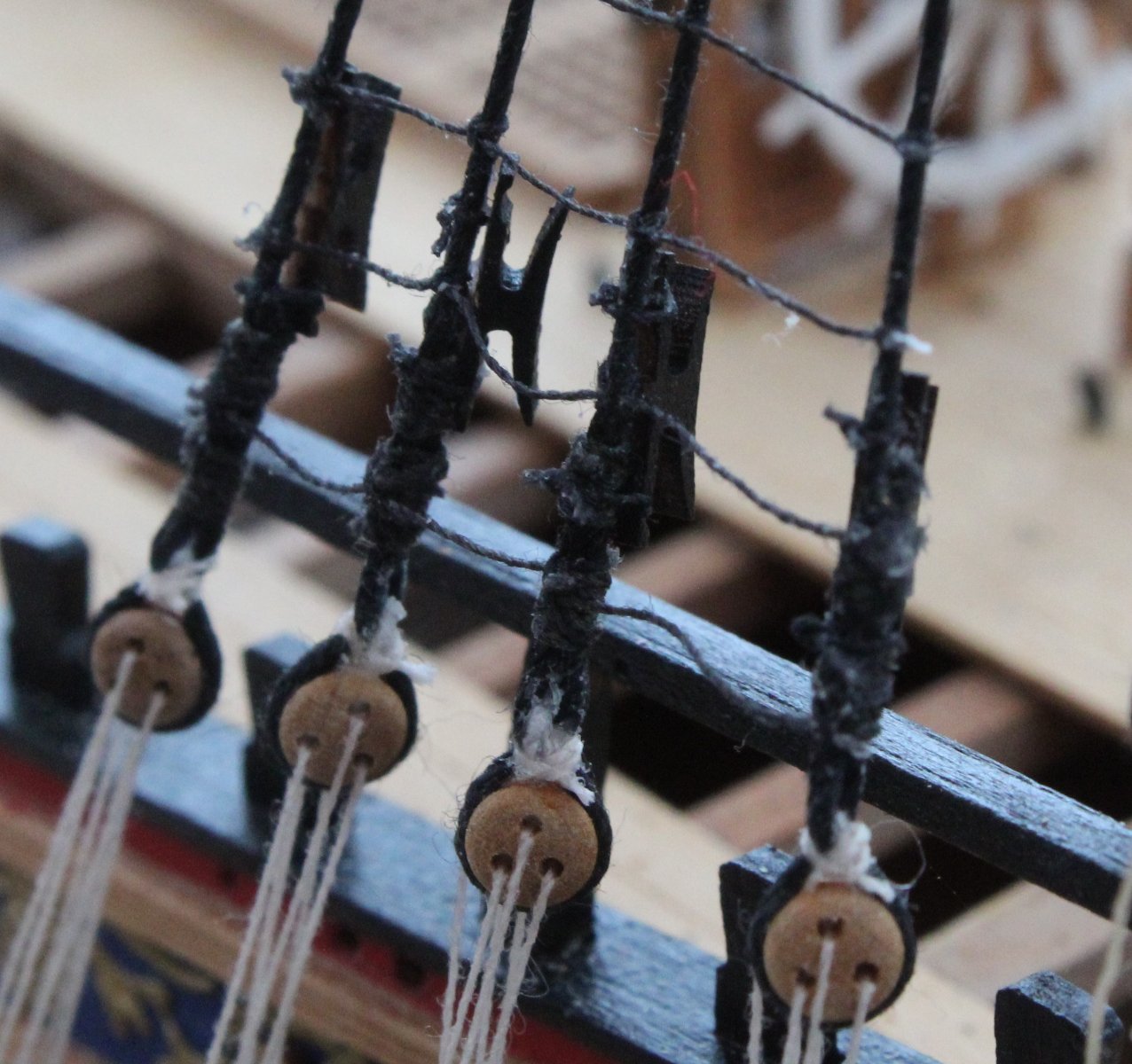
Shroud Cleats In my last post I detailed that I had failed to add the shroud cleats. I thought would share the process I am now using to add them. With the cleat held in the quad hands I use a simple half hitch to add a 15cm length of black thread. I am using left over ratline thread. I only add the thread to one side of the cleat at this stage. It seemed to make task of securing the cleat to the shroud much harder when I had added the seizing thread to both sides of the cleat at this stage. As can be seen below, showing the work in progress, I am making this a production line task. When adding the cleat to the shroud I apply a bit of ca gel to the cleat and press it in place, ensuring the thread that had been attached is at the bottom. The two thread ends are brough to the front I use a standard reef knot to secure the bottom thread ends and, after adding a touch of ca gel to the knot, the excess thread is cut away. I then take a 10cm length of black thread and position it around the cleat and shroud which is then secured with another standard reef knot. In the picture below I have started to add the reef knot to the top section of the cleat.

- 476 replies
-
- 5
-
-
- sphinx
- vanguard models
- (and 1 more)
-
Yard Lifts - A Slight Setback As I set to work adding the various yard lift rigging, I did not foresee too many problems. I started out making the loops the lifts which needed to be secured to the end of the yards. Some yard lift rigging started by being seized around their respective masts, just above the mast cap. These were added without incident. As each lift thread was added and fed through the appropriate blocks the free ends were then carefully brought down to the deck level ready for belaying. After a few hours work all the yard lifts had been rigged and were ready to be belayed. I was really pleased with the how the Sphinx was looking. I expected it would take me another days effort to belay all the free ends. When looking at the rigging plans I noted that all the yard lifts are belayed to cleats located on the back of the shroud lines. They only problem is that I had forgotten to add these cleats when installing the shrouds. The various stay rigging which has been belayed to the various channels has meant access to the back of the shrouds is now much more difficult. I now in the process of adding all the shroud cleats which is a very fiddly and very time-consuming task, but I am making slow and steady progress. I expect it will take me a few days effort before all the shroud cleats have been added which is a minor setback.


- 476 replies
-
- 4
-
-
- sphinx
- vanguard models
- (and 1 more)
-
Hi Dan I was dreading cutting out the Alert gun ports but they are actually quite easy to do. Check out post 80 on my Alert build log where I added the gun port cut outs. I used tape as a guide and a razor saw to make the vertical cuts. Glenn
- 59 replies
-
- 2
-
-
- saucy jack
- fishing smack
- (and 2 more)
-
I have found (several times when I've made an error) that Chris is pretty efficient at sending replacements so I would assume they will arrive early next week. I plan to build Saucy Jack in parallel with Erycina. My Sphinx build is nearing completion so I hope to start these new builds next month. The Alert is a nice looking boat and one I really enjoyed building. I think you will not encounter too many problems with that kit.
- 59 replies
-
- 1
-
-
- saucy jack
- fishing smack
- (and 2 more)