Glenn-UK
-
Posts
3,175 -
Joined
-
Last visited
Content Type
Profiles
Forums
Gallery
Events
Everything posted by Glenn-UK
-
 Titebond Original (with map pins) is good as it grips fairly quickly. Also Super Phatic is a good fast gripoing glue which is a mix of wood and super glue. I will check out Veloset, thanks for the heads up.
- 62 replies
-
- 1
-

-
- Saucy Jack
- vanguard models
- (and 3 more)
-
It is certainly much quicker using Gorilla Gel and I know plenty of other builders use super glue without any issues. I think I need to refine my method, probably trying to glue a plank in smaller sections rather than trying to glue a full plank all at once. Glenn
- 62 replies
-
- 1
-
-
- Saucy Jack
- vanguard models
- (and 3 more)
-
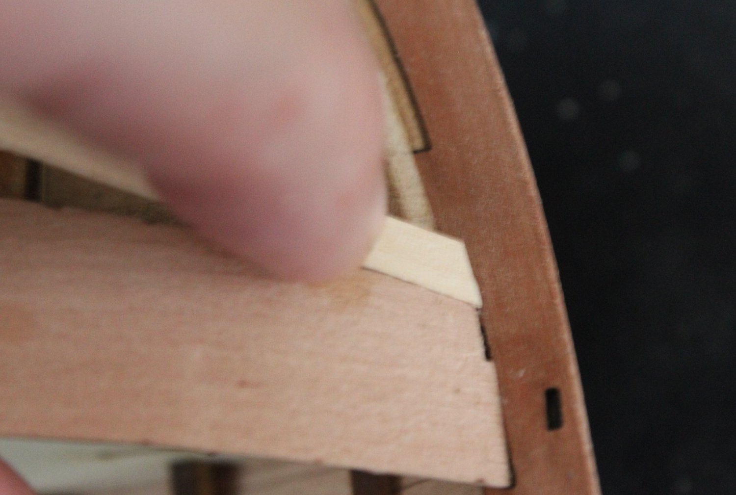
Hello Craig I did not edge bend. I have tried edge bending a few times on other models but I have found normally just tapering the planks is more than good enough. It may have gone better if I had followed Chucks method for tapering and edge bending the planks. In the past I have used wood glue and map pins when adding the second planking layer to very good effect. This time I used Gorilla Gel super glue which seemed to cause me no end of problems. I think I ended up with more glue on my fingers. I am confident that once the hull smoothing and painting process is complete it will be OK.
- 62 replies
-
- 1
-
-
- Saucy Jack
- vanguard models
- (and 3 more)
-
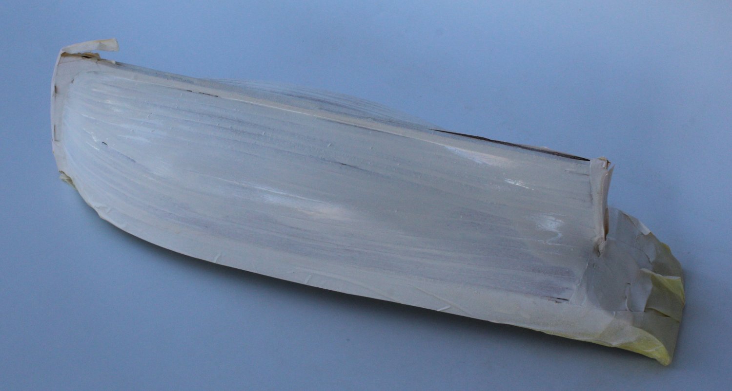
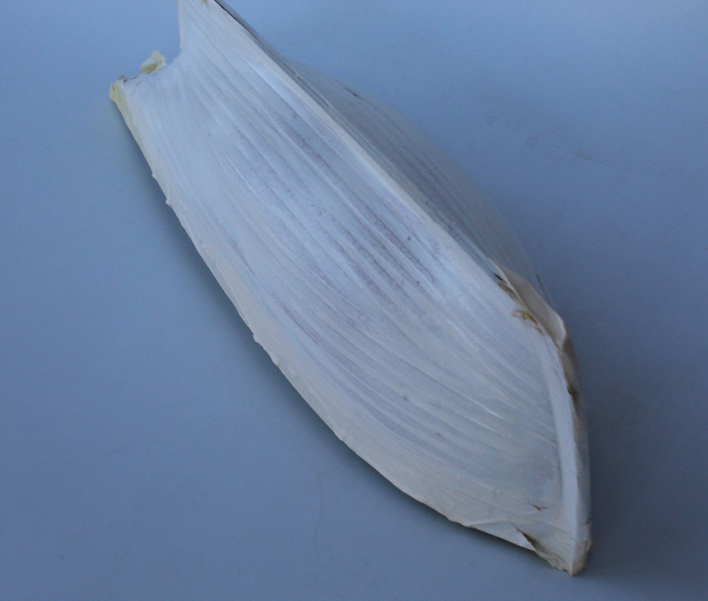
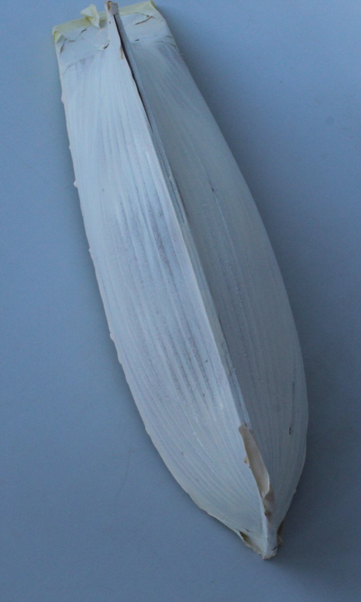
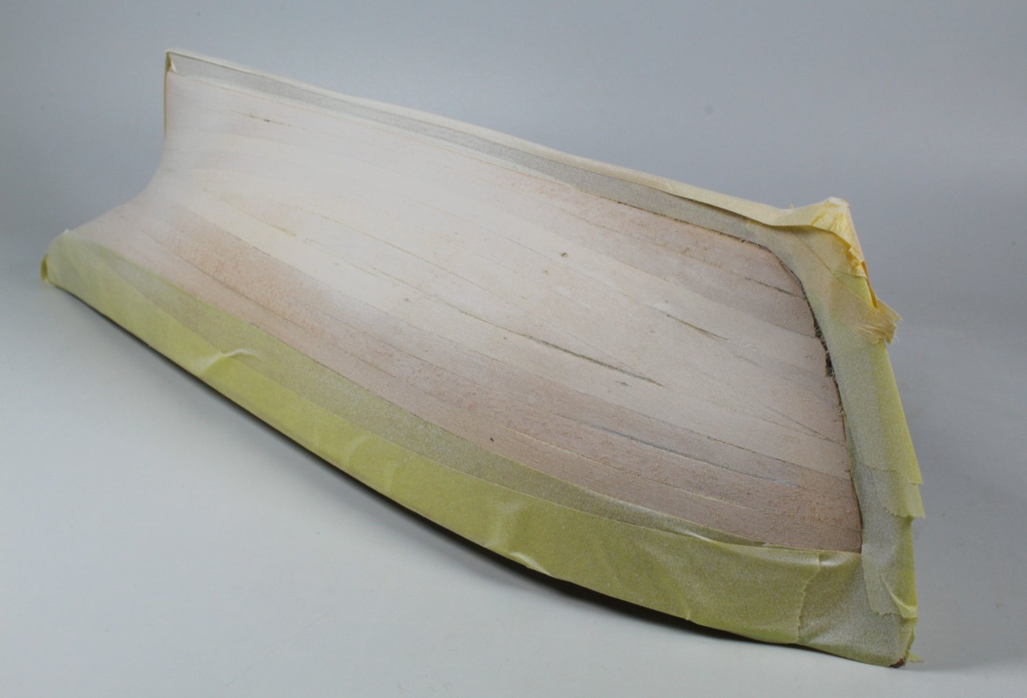
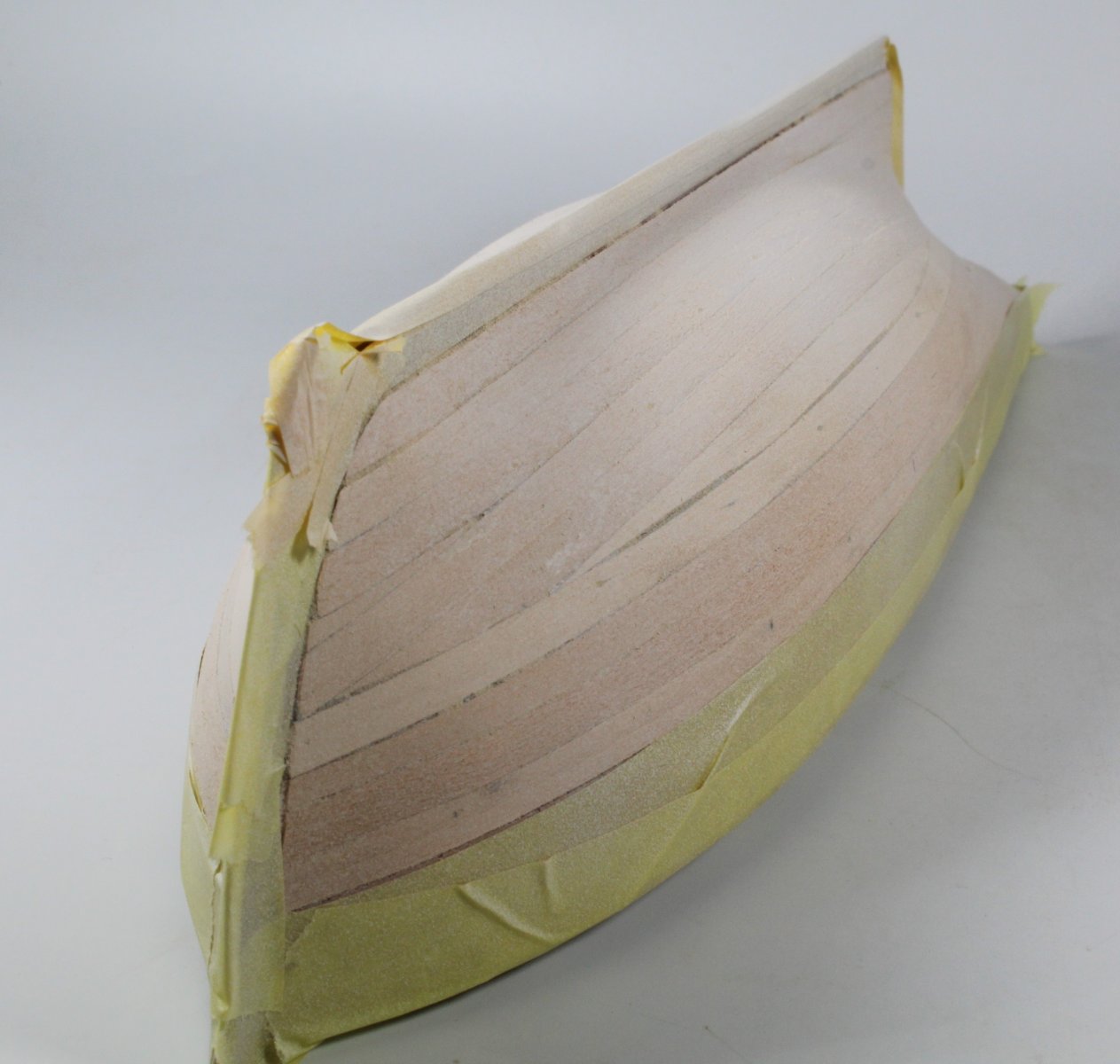
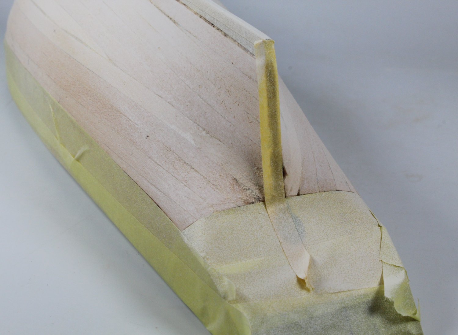
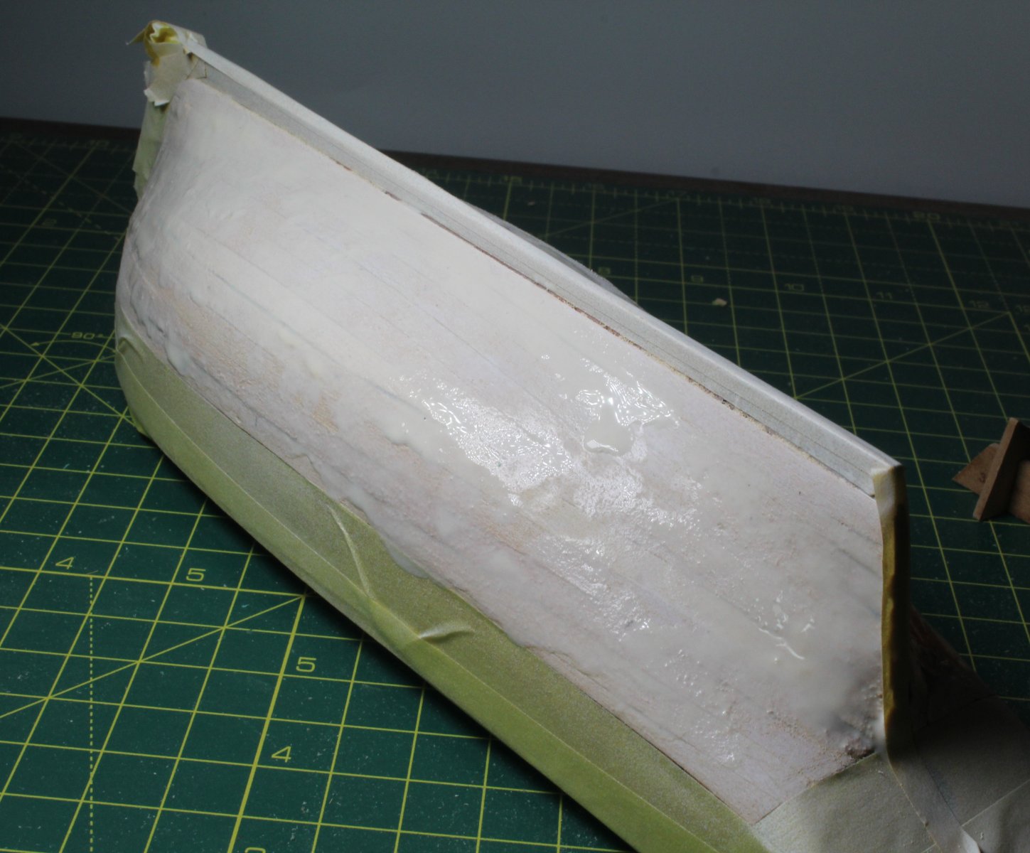
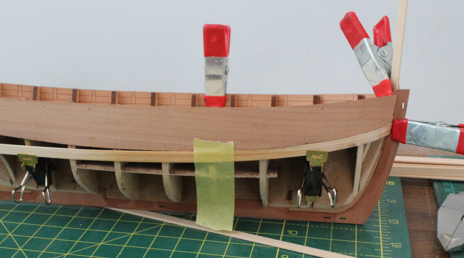
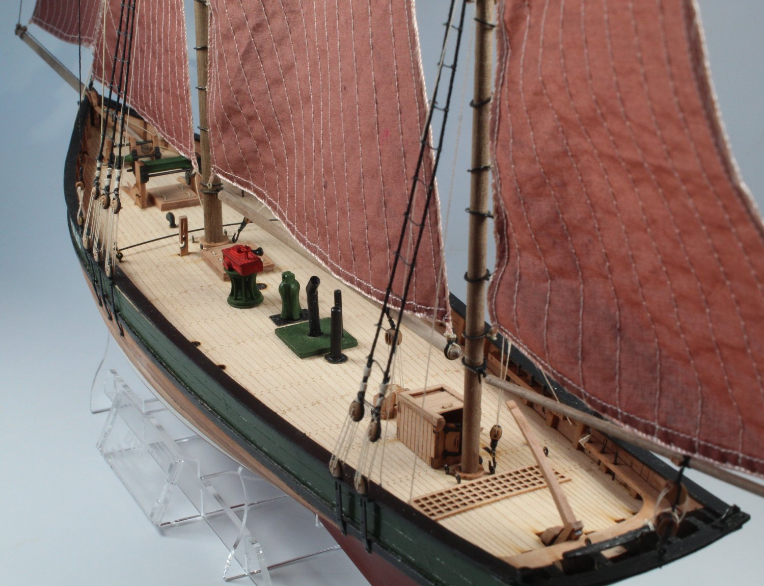
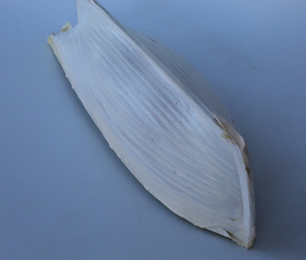
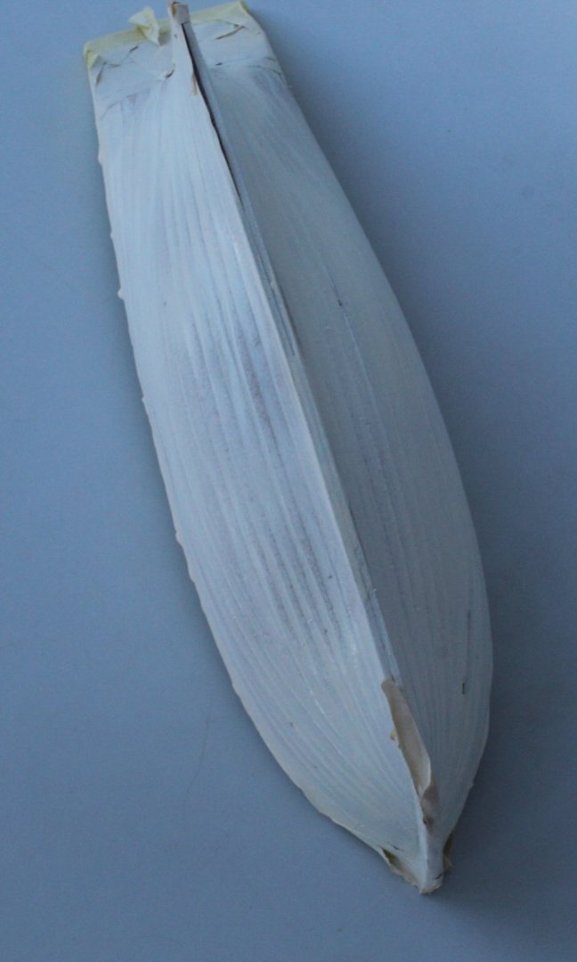
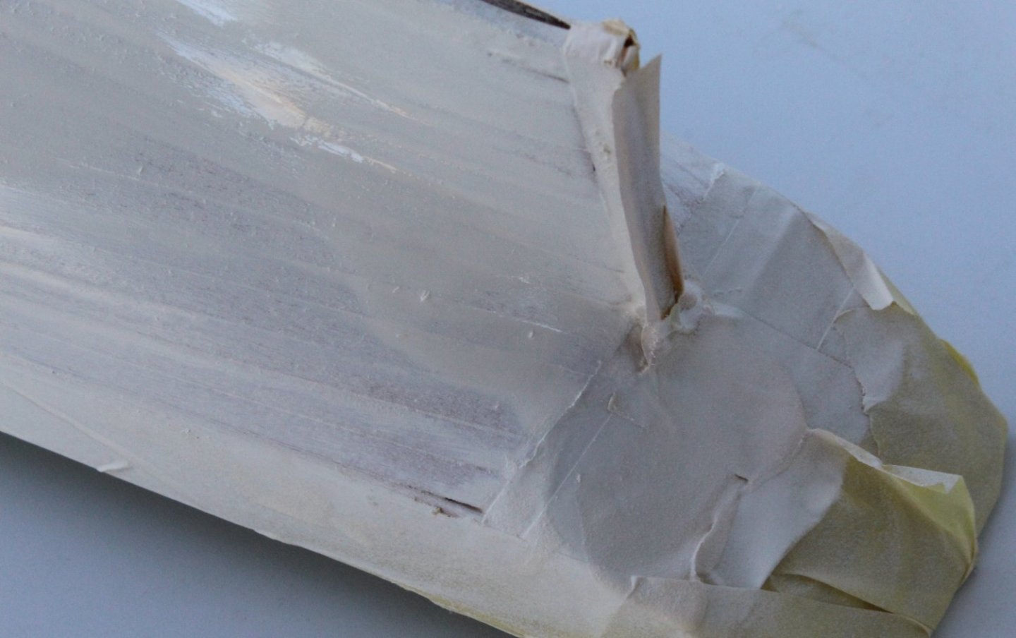
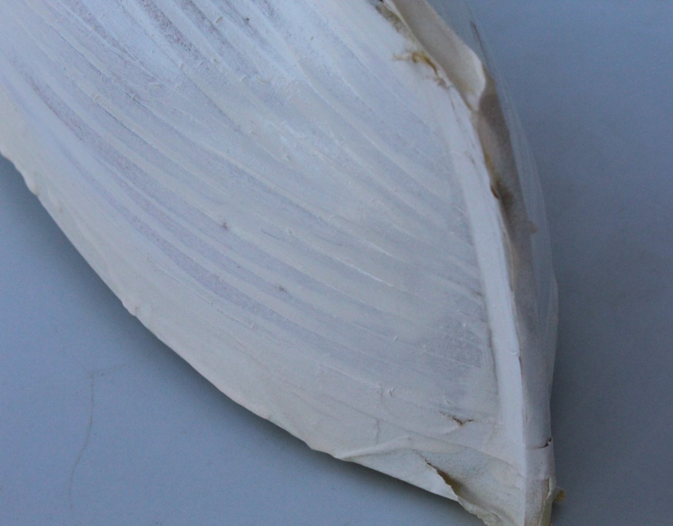
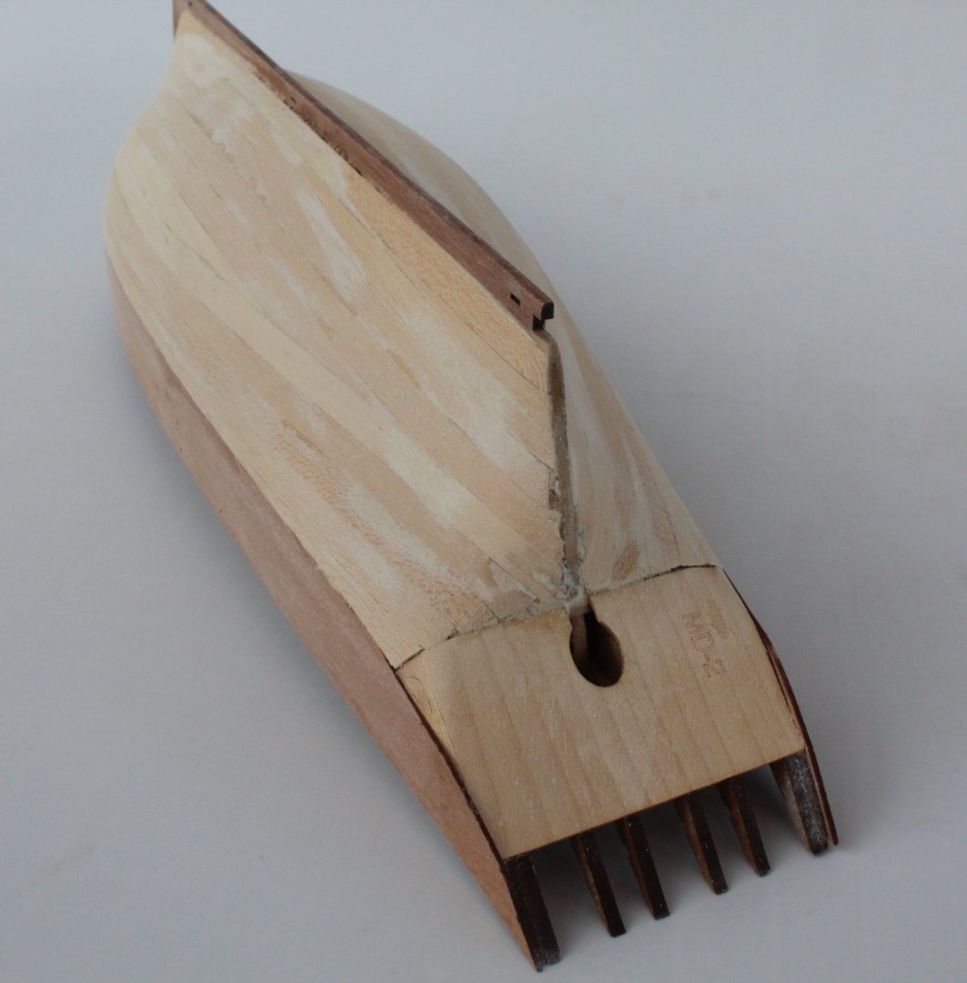
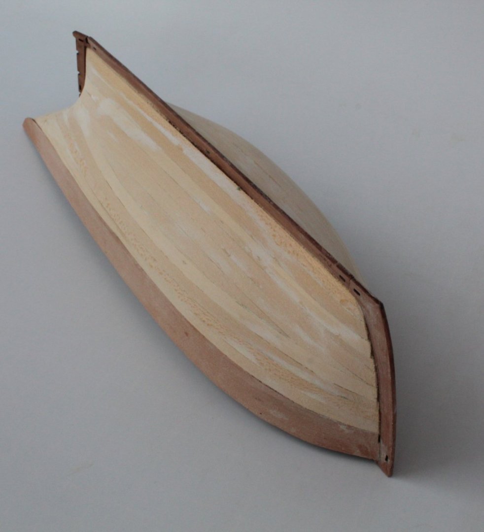
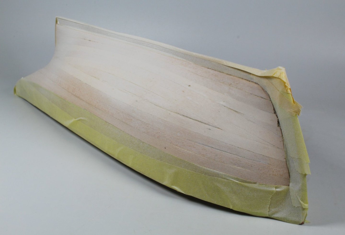
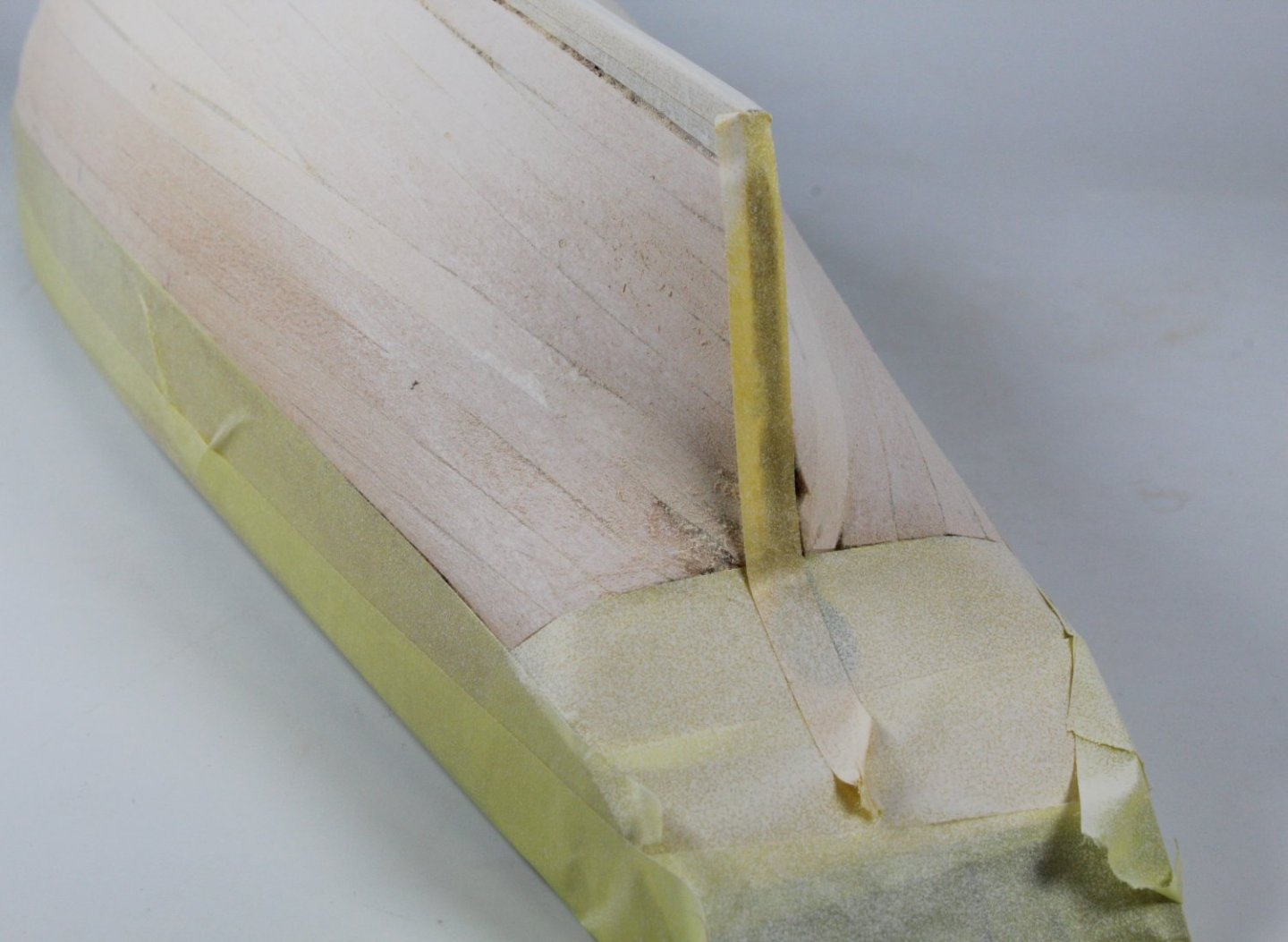
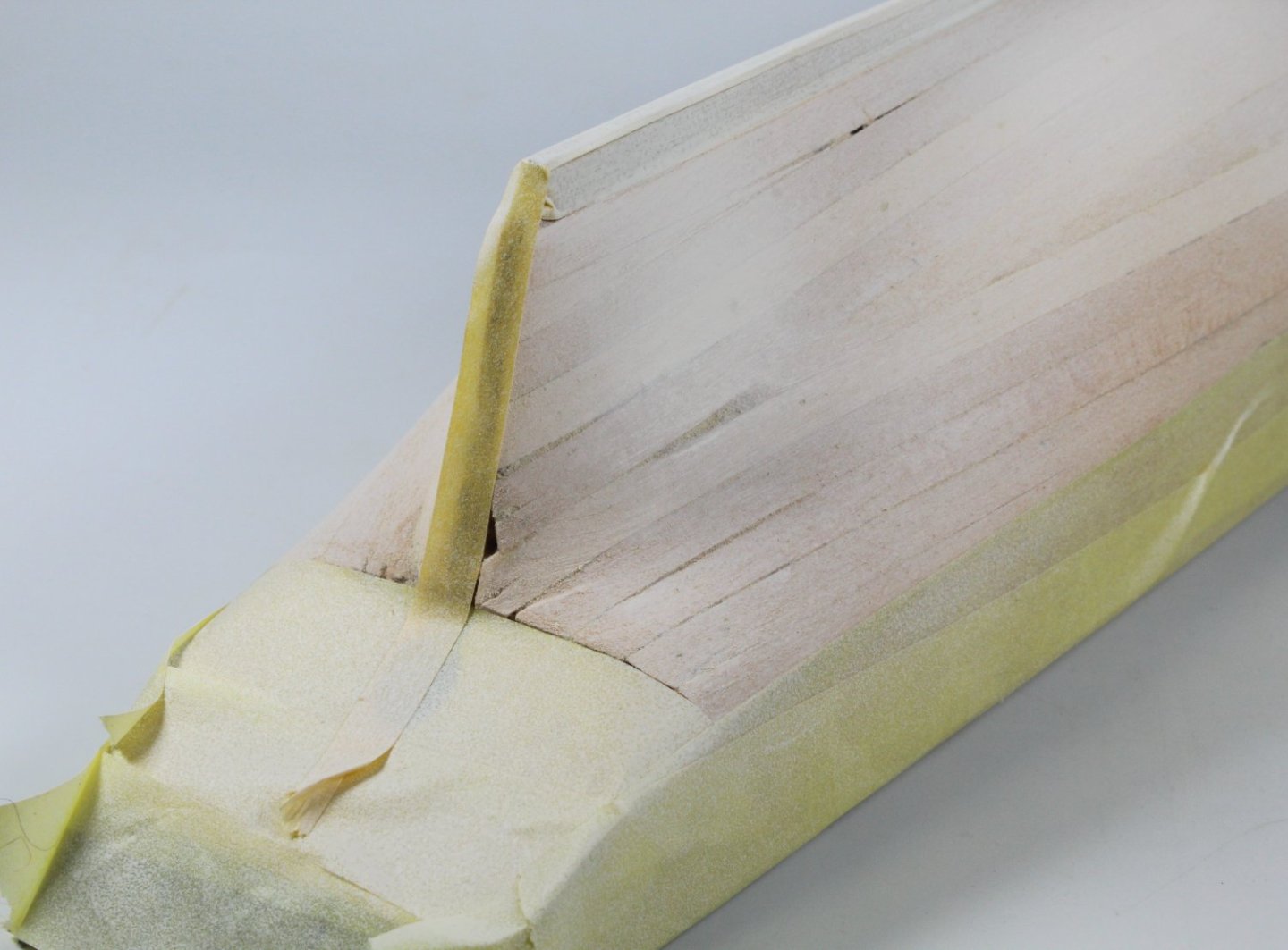
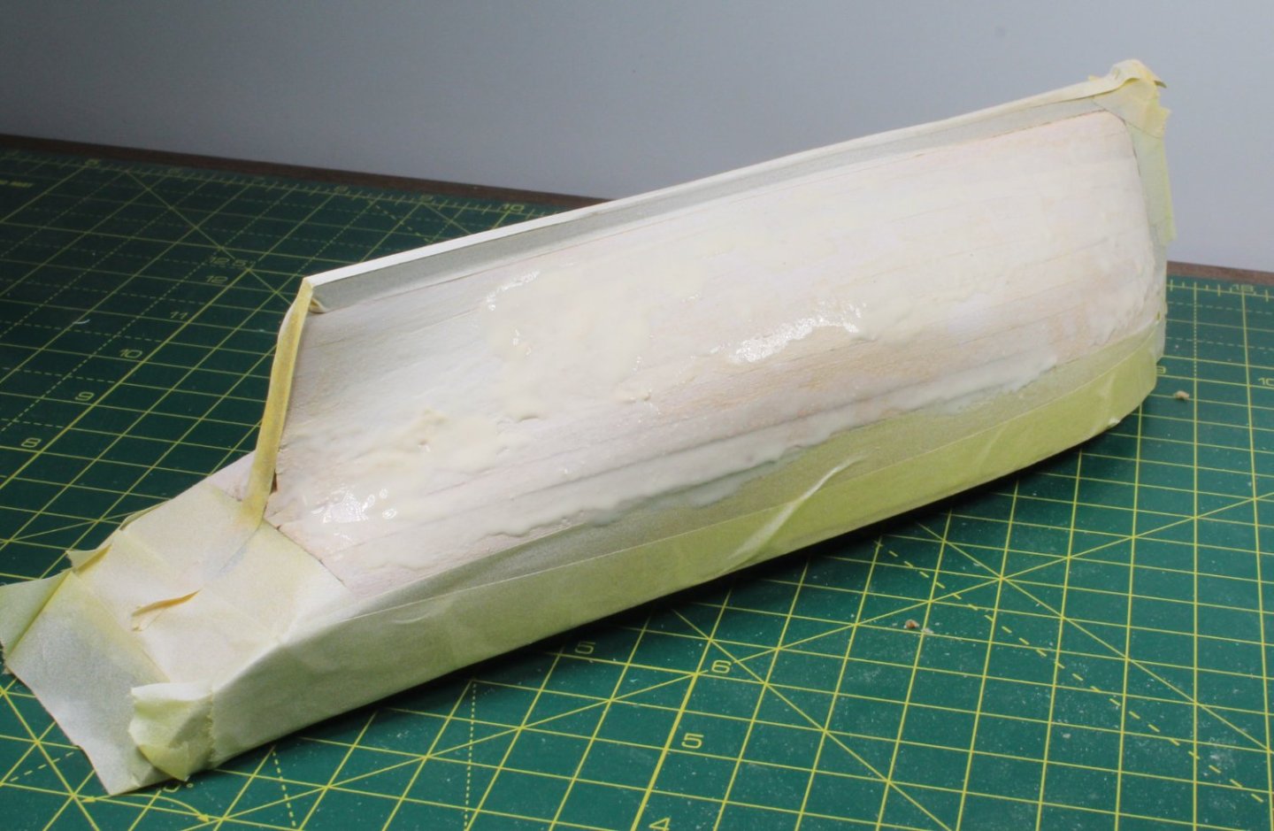
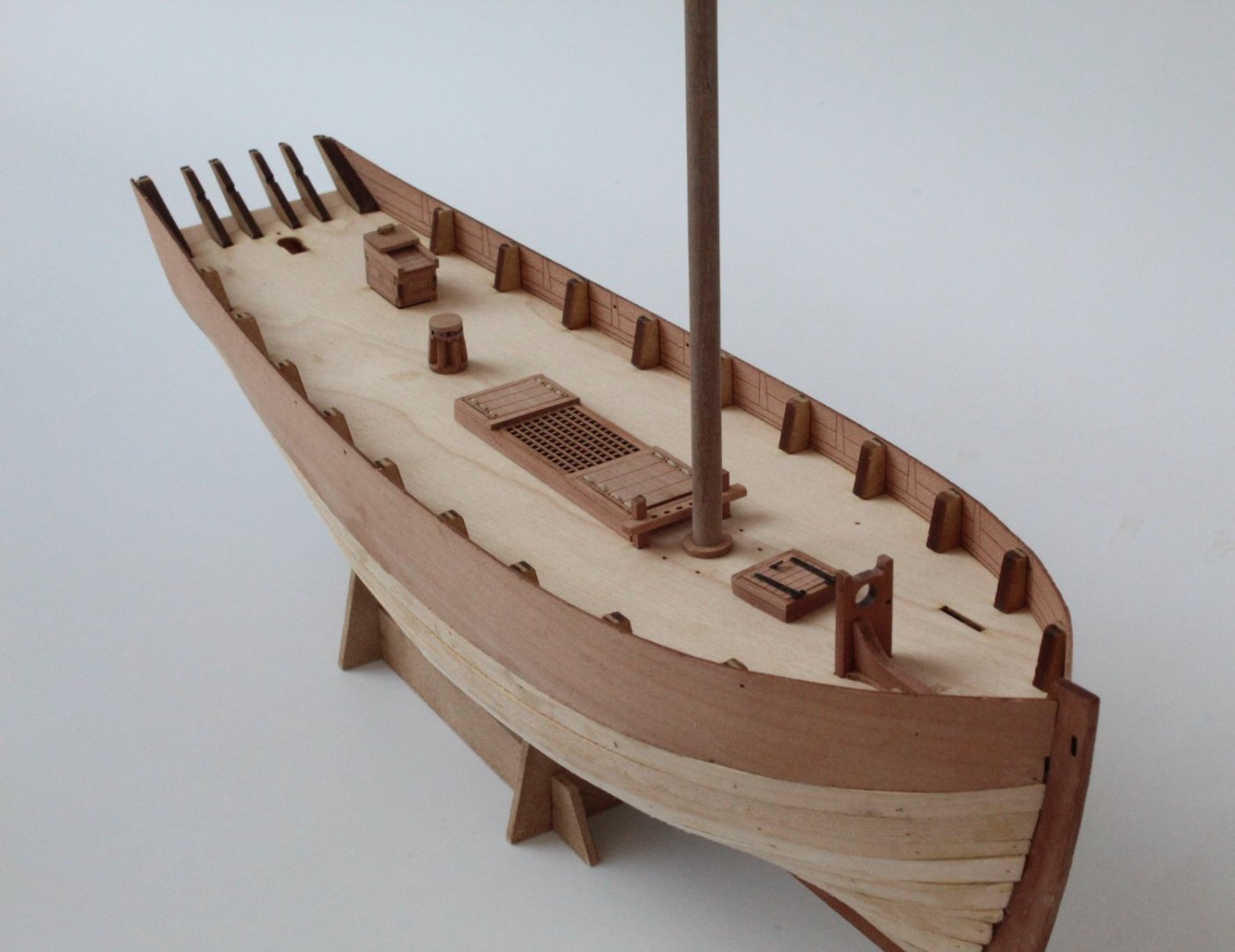
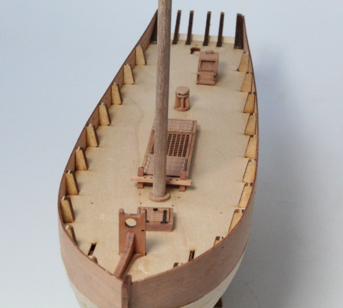
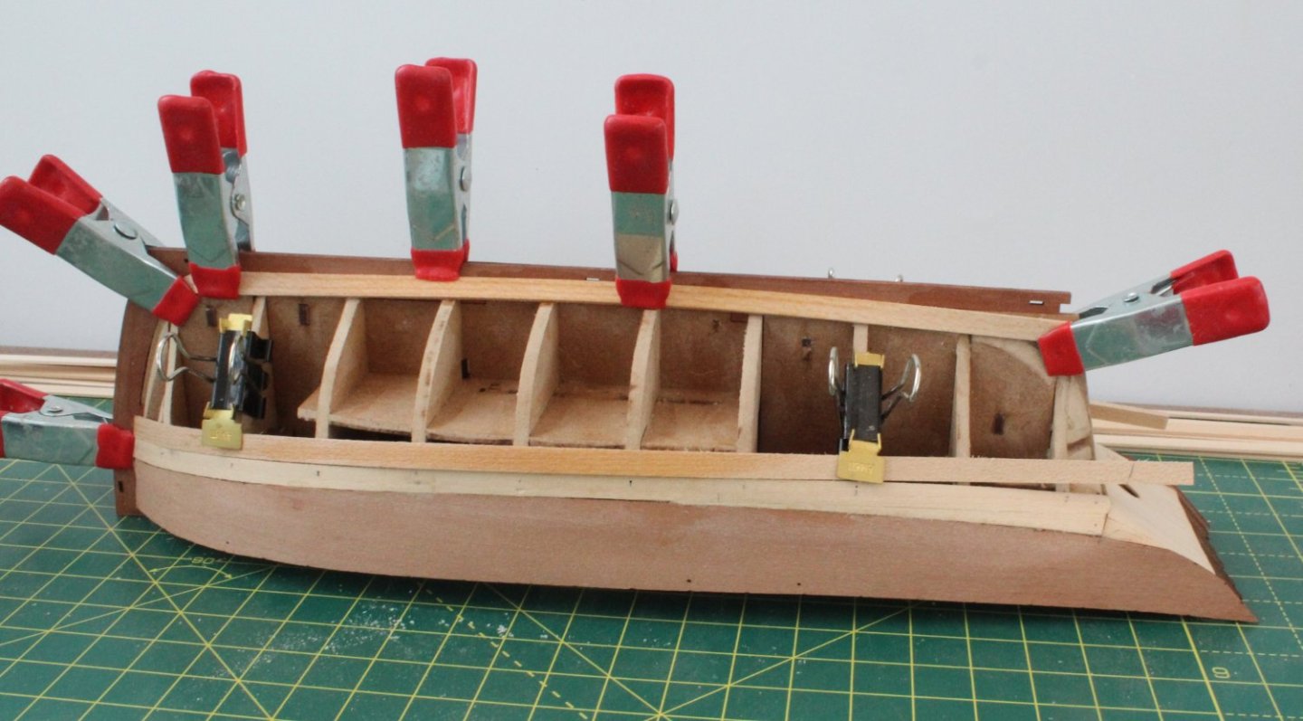
012 - Second Planking I have made more progress with the Saucy Jack build and I have now completed the second planking. I have to admit that with all the models I have built this is, by far, my worst attempt at the second planking phase. I had a perfectly smooth hull as the base and I bent and shaped the planks as they were fitted. Despite all that I ended up with a very clinkered bow section and the stern area was not much better. I have now decided on a painting scheme that, once the second planking has been filled and sanded smooth, should not show the errors of my second planking. The upper bulwarks will be painted flat green down to the upper rail. Both the upper rail and main wale will be painted black. The area between the upper rail and main wale will be painted white. The area below the main wale will also be painted white down to the water line. Finally the area below the water line will be painted with red oxide. The pictures below show I have masked the hull and then sprayed it with white primer to highlight all the problem areas, noting this is the second iteration as I had already painted, filled, sanded and repainted the hull before these photos were taken. The photos still show the level of my poor workmanship in respect to the second planking. It is now a case of more iterations of sand, fill, paint, sand, fill, etc until the hull looks and feels smooth so in the end no one will be any the wiser. This will take a few days to complete as I have to allow time for the paint to dry before the filler mixture can be added. I then have to allow time for the filler mixture to cure before I can start sanding.

- 62 replies
-
- 1
-
-
- Saucy Jack
- vanguard models
- (and 3 more)
-
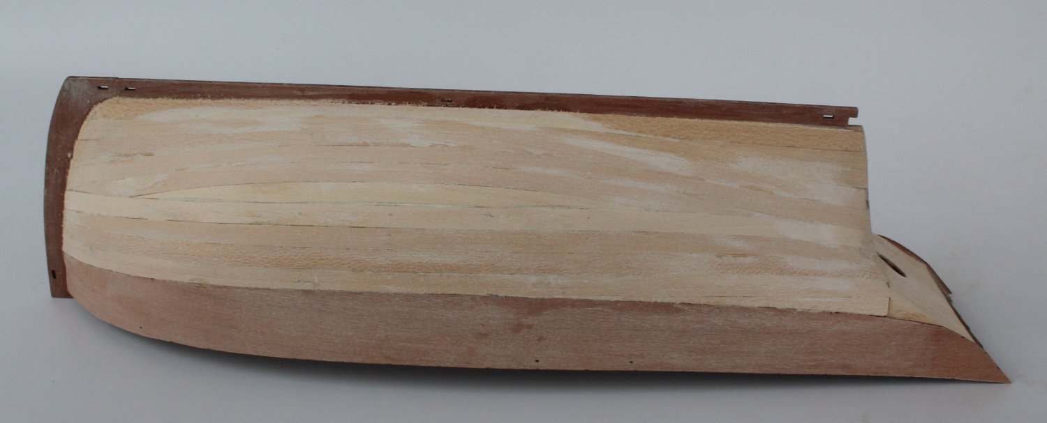
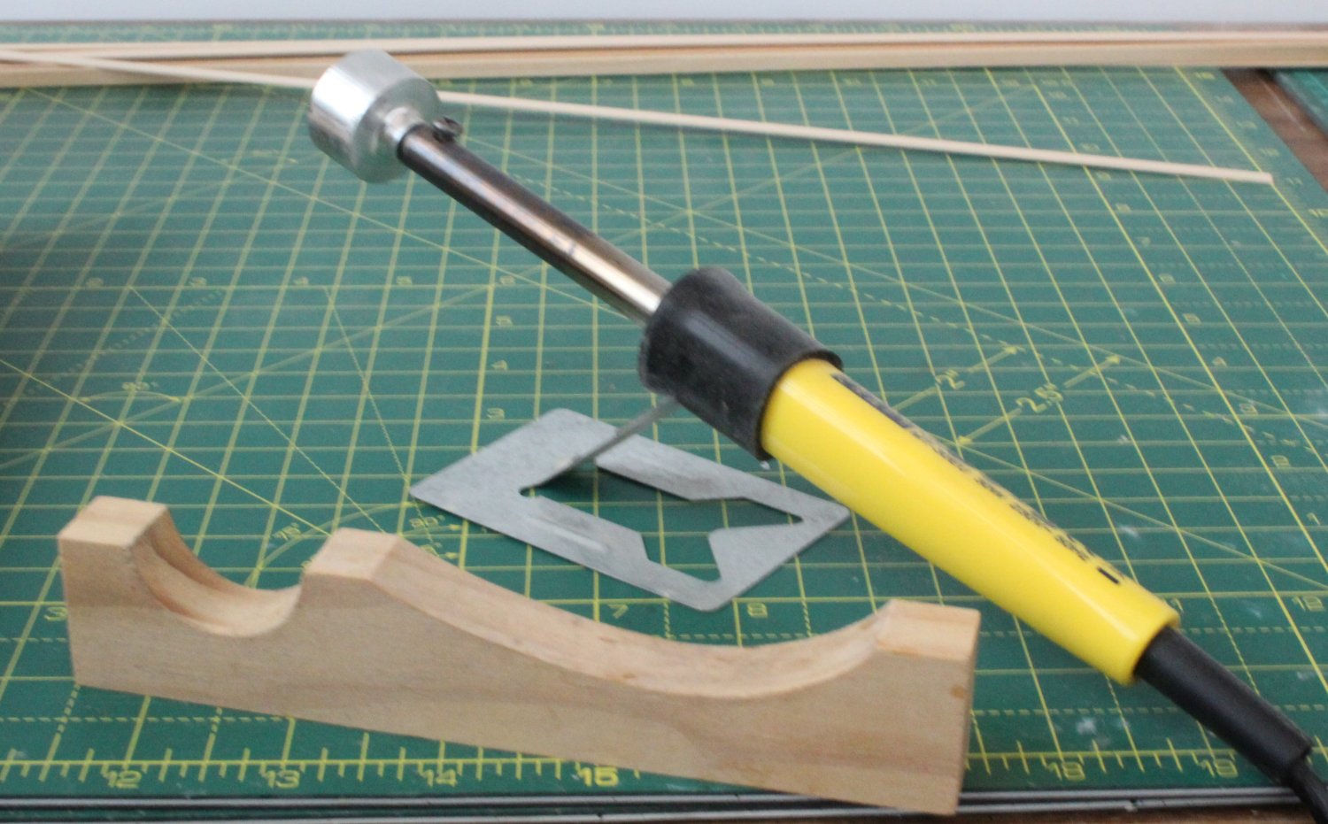
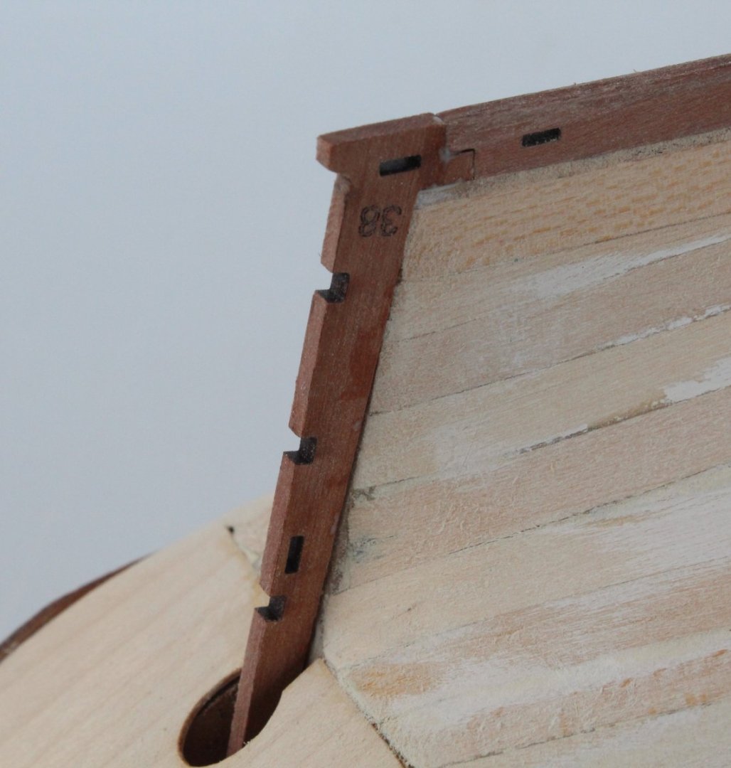
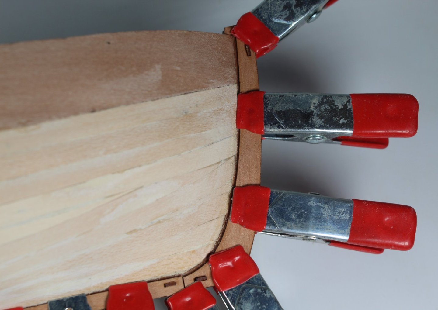
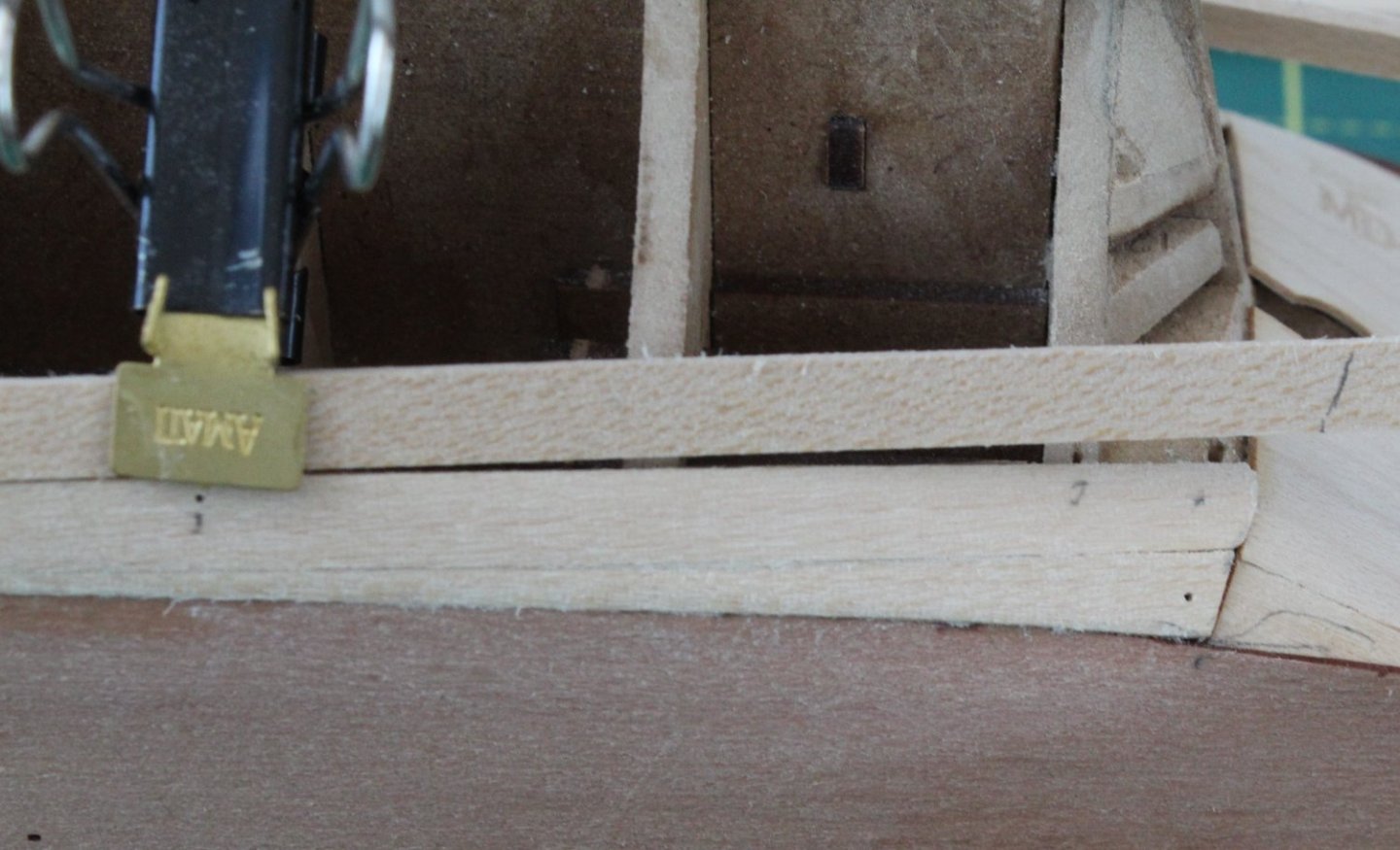
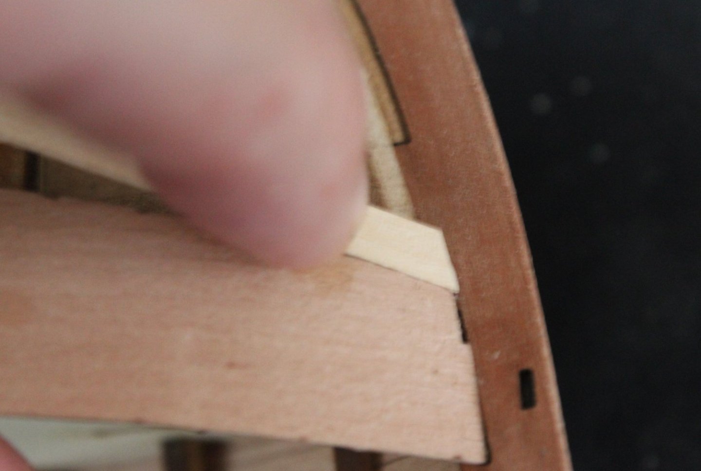
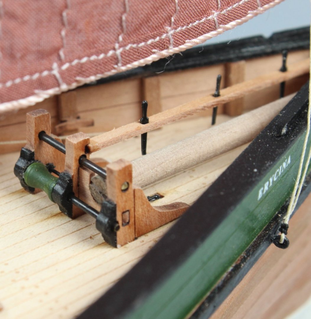
011 - Smoothing and Rabbet Patterns As detailed in my last post I had sprayed the hull with a light coating of white paint and then used a filler solution as required. I was able to find a couple of hours in the shipyard today so I proceeded to sand the hull so the white paint and excess filler could be removed. The end result is that I now have a smooth hull which is ready for the second layer of planking. I added the rudder post without any issues. The final task was to add the outer rabbet patterns to the stem post, keel and rudder post. I used all my clamps when adding these patterns and the patterns lined up perfectly when the various locating pins where inserted.


- 62 replies
-
- 4
-
-
- Saucy Jack
- vanguard models
- (and 3 more)
-
Hello Jonathan That would have been me at Dalby Parkrun as I do run there most weekends. I have no memory of running in a penguin suit, however but my wife does remember.
-
Hello Jonathan A light spray of white paint really does highlight the problems. It is not strictly necessary for the first planking as the real smoothing is done once the second planking has been added. I thought I would try it after the first planking to get a better base for the second planking as I'm in no hurry to complete this build. I might be missing something obvious sorry, as I do not understand the penguin suit reference.
-
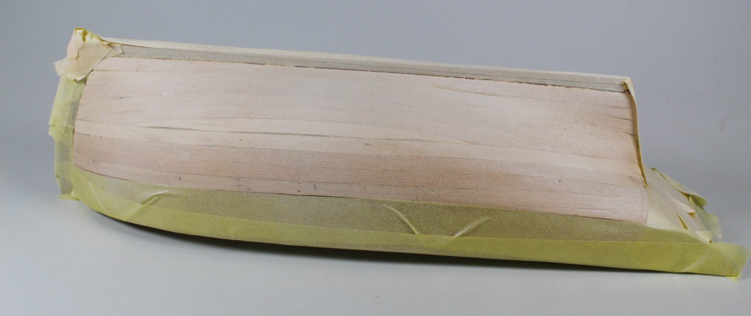
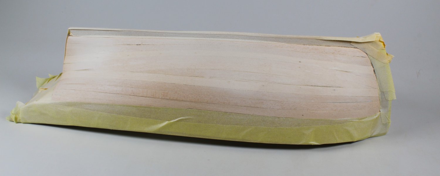
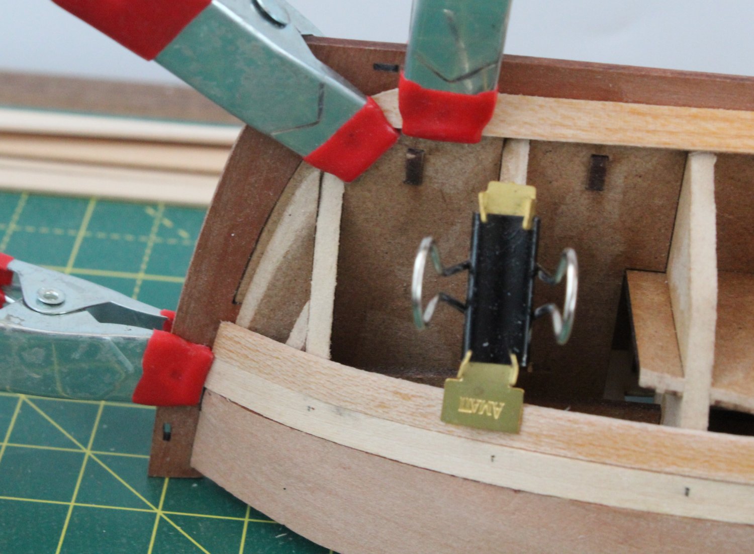
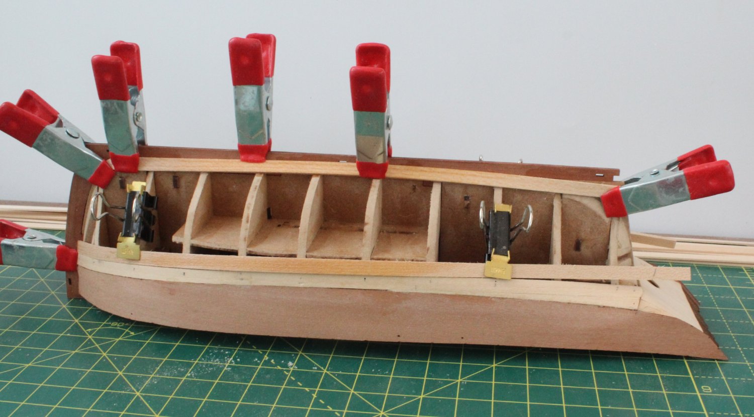
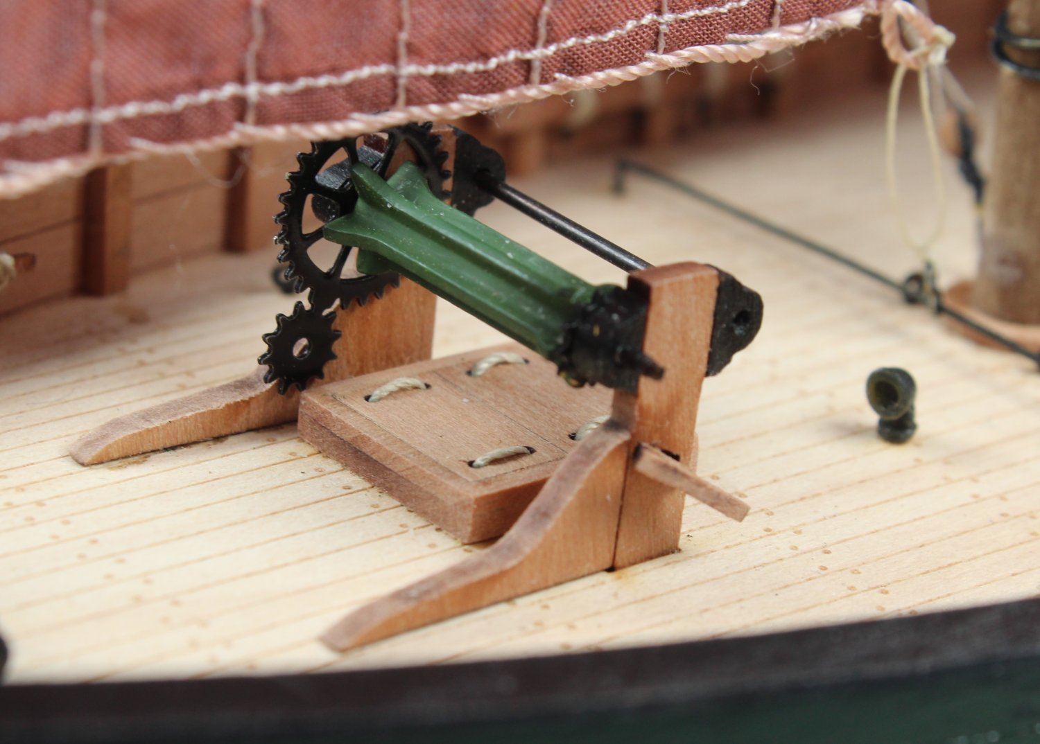
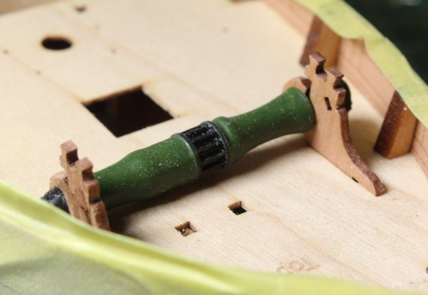
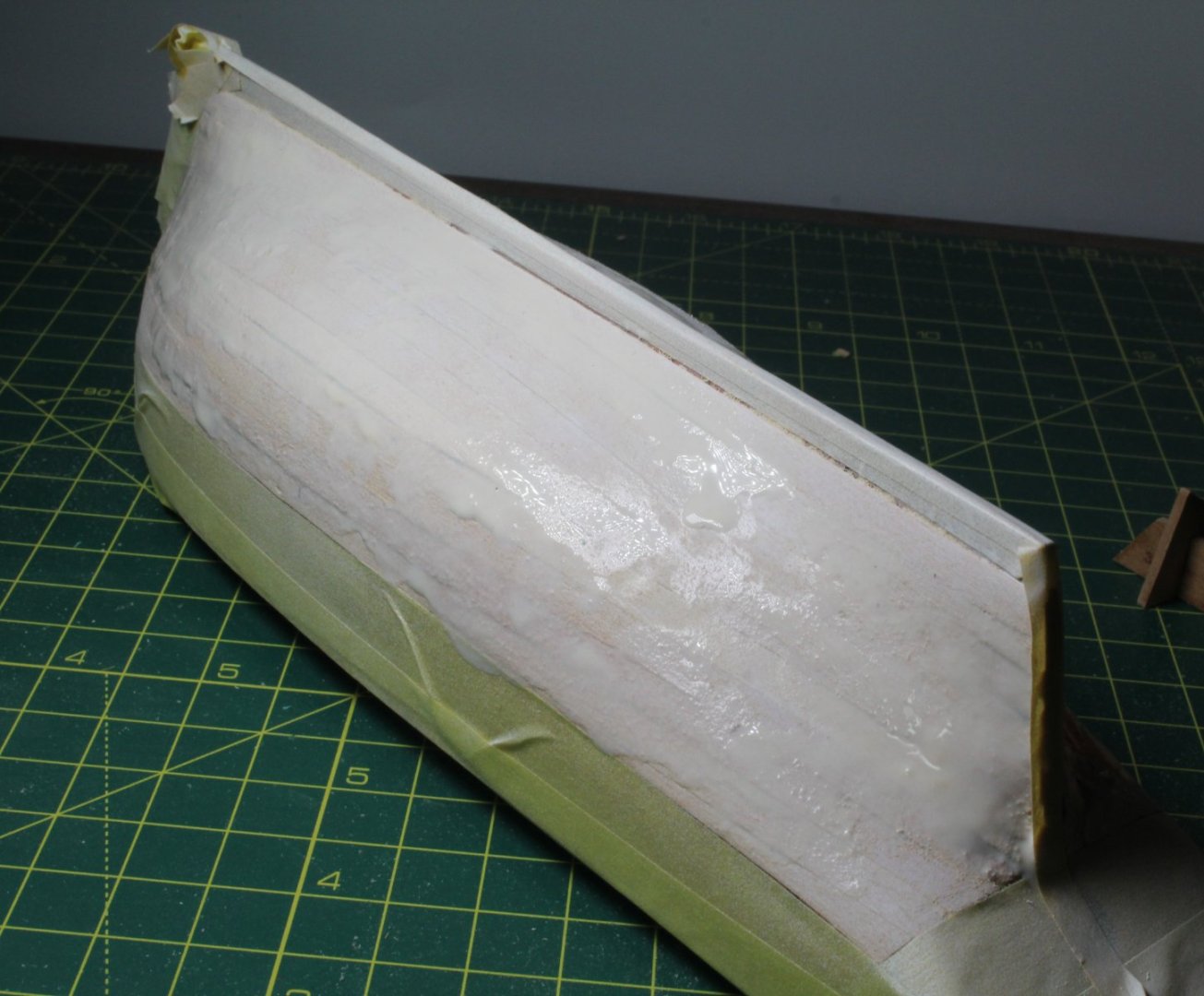
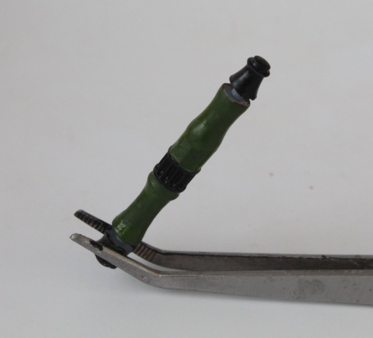
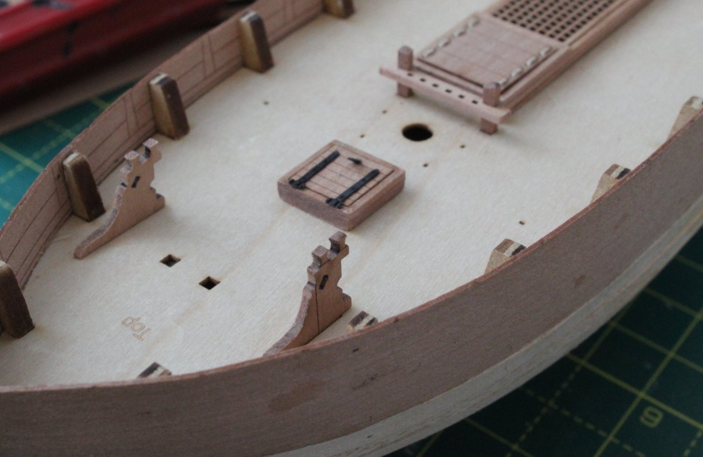
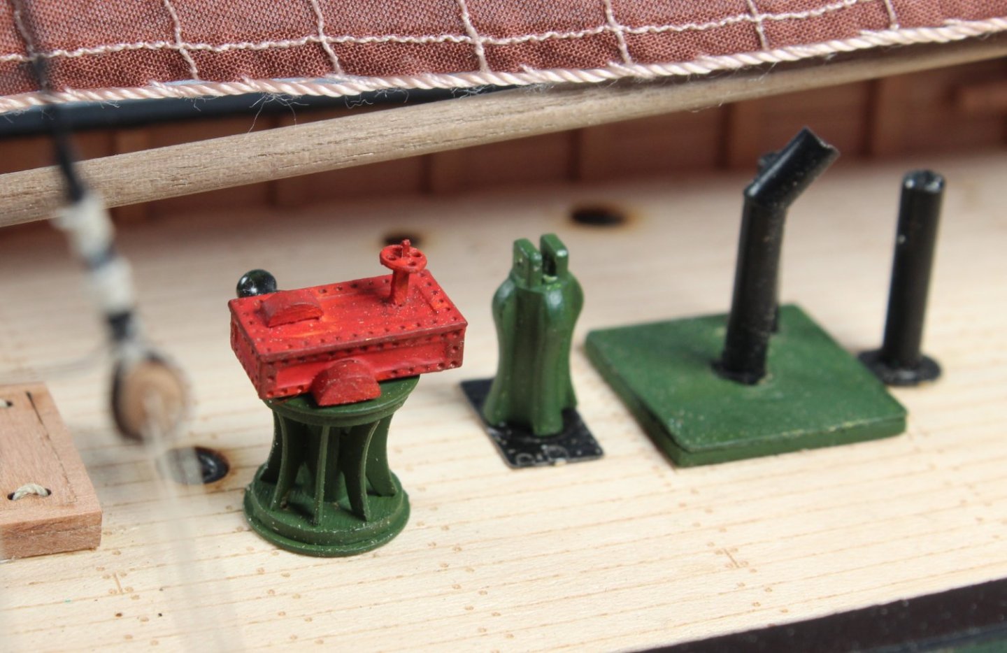
010 - Prework for getting a smooth hull after first planking. I was not intending to post again until I had completed the hull smoothing process. Then I remembered that my wife and I are looking after some of our grandsons over the next four days so I will have very limited time, if any, in the shipyard. This afternoon I started to sand the hull smooth, using some 120-grit sandpaper. After an about an hour the hull felt smooth to the touch and looked very smooth. I decided on a belt and braces method to be absolutely sure. After taping the hull, so only the first layer of planking was visible, I gave the hull a very light spray with white paint. This will highlight any problem areas with the hull, not readily noticeable to either sight or touch. As can be seen in the first collection of photos below the hull does not look too bad but there are a few areas which needs a bit of attention. I mixed up a filler solution, which comprised 50% wood filler, diluted with water and 50% titebond original. Using a paint brush the filler solution was applied to the hull. Once it has had time to fully cure, I can sand the hull again so all of the paint and excess filler mix can be removed leaving a nice smooth hull which is be ready for the second planking layer. The assembled windlass was test fitted to the hull. I did manage to break one of the two cleats. I will have to search my other kits to see if I can find a suitable replacement, as I have been unable to repair the damage. I think using the flat green paint was the correct way to go when painting the resin part.


- 62 replies
-
- 2
-
-
- Saucy Jack
- vanguard models
- (and 3 more)
-
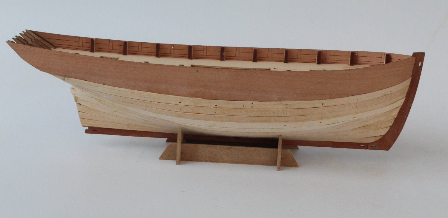
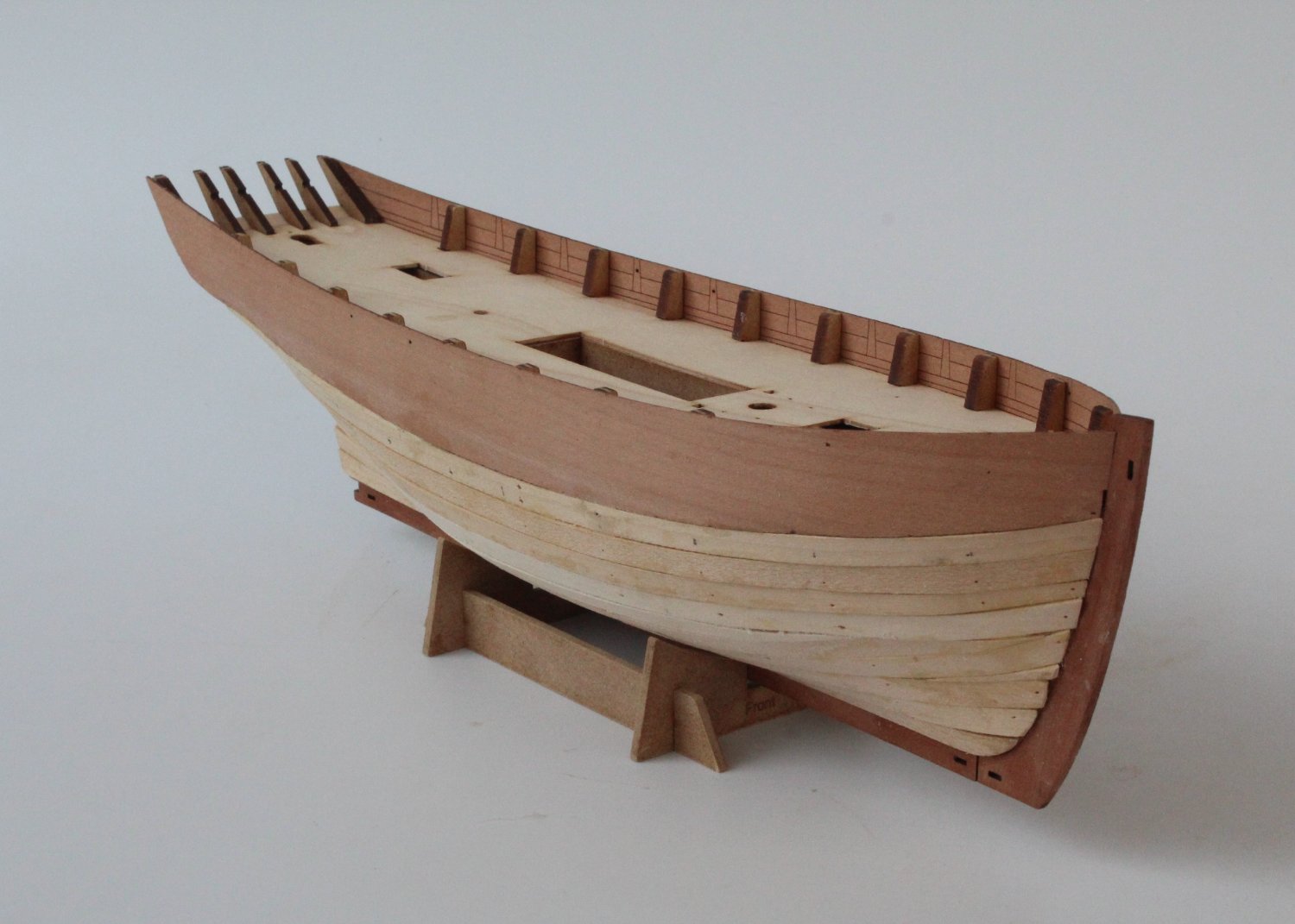
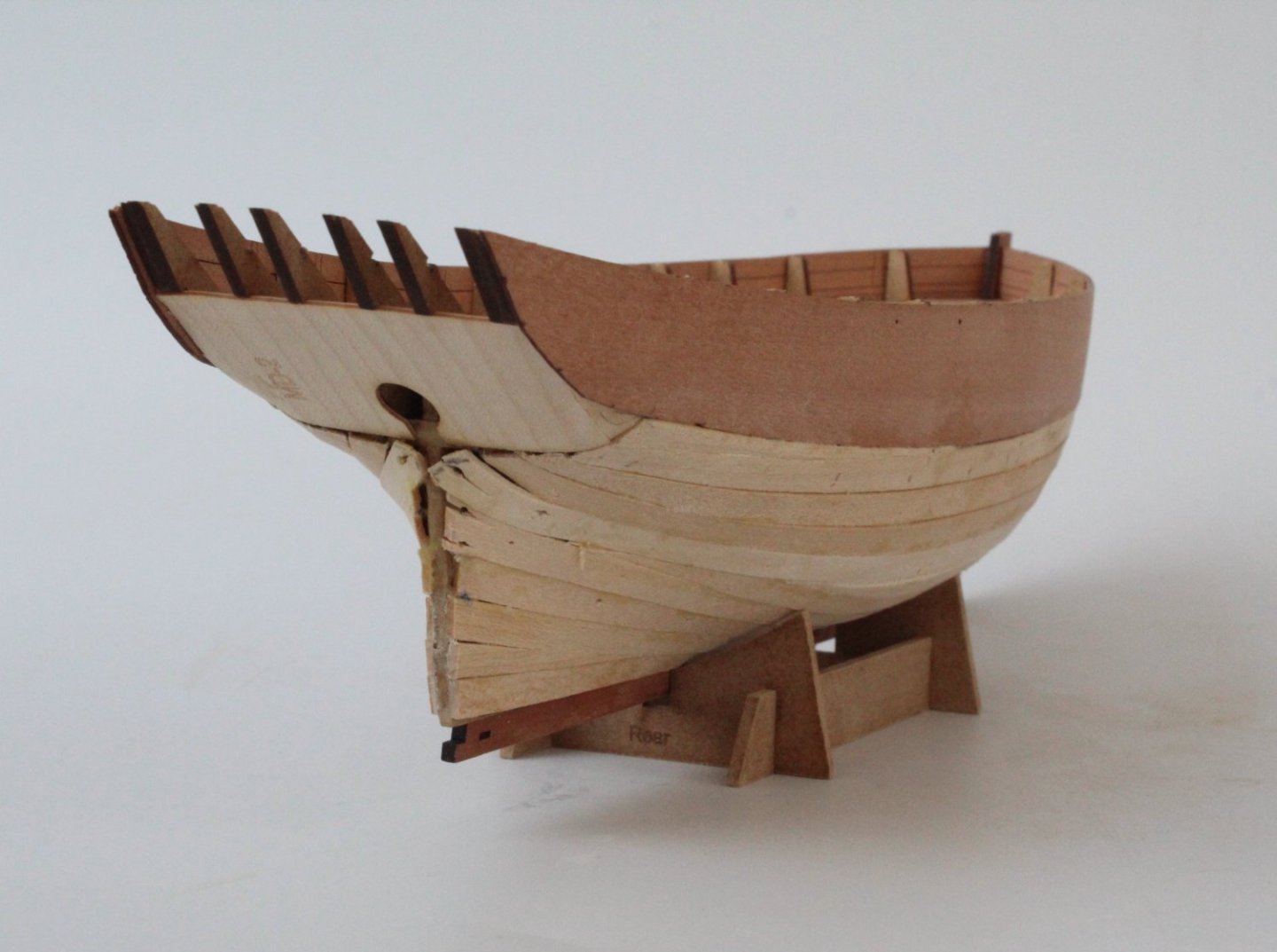
009 - 1st Planking Completed I have now completed the 1st planking and the hull is now ready for sanding smooth. I have added a selection of photos showing the un-sanded planked hull. I have also taken some photos with the deck items placed on the deck. I had originally painted the windlass a wood walnut colour. As I was not happy with the end result and repainted using a flat green colour and I think it looks much better.


- 62 replies
-
- 4
-
-
- Saucy Jack
- vanguard models
- (and 3 more)
-
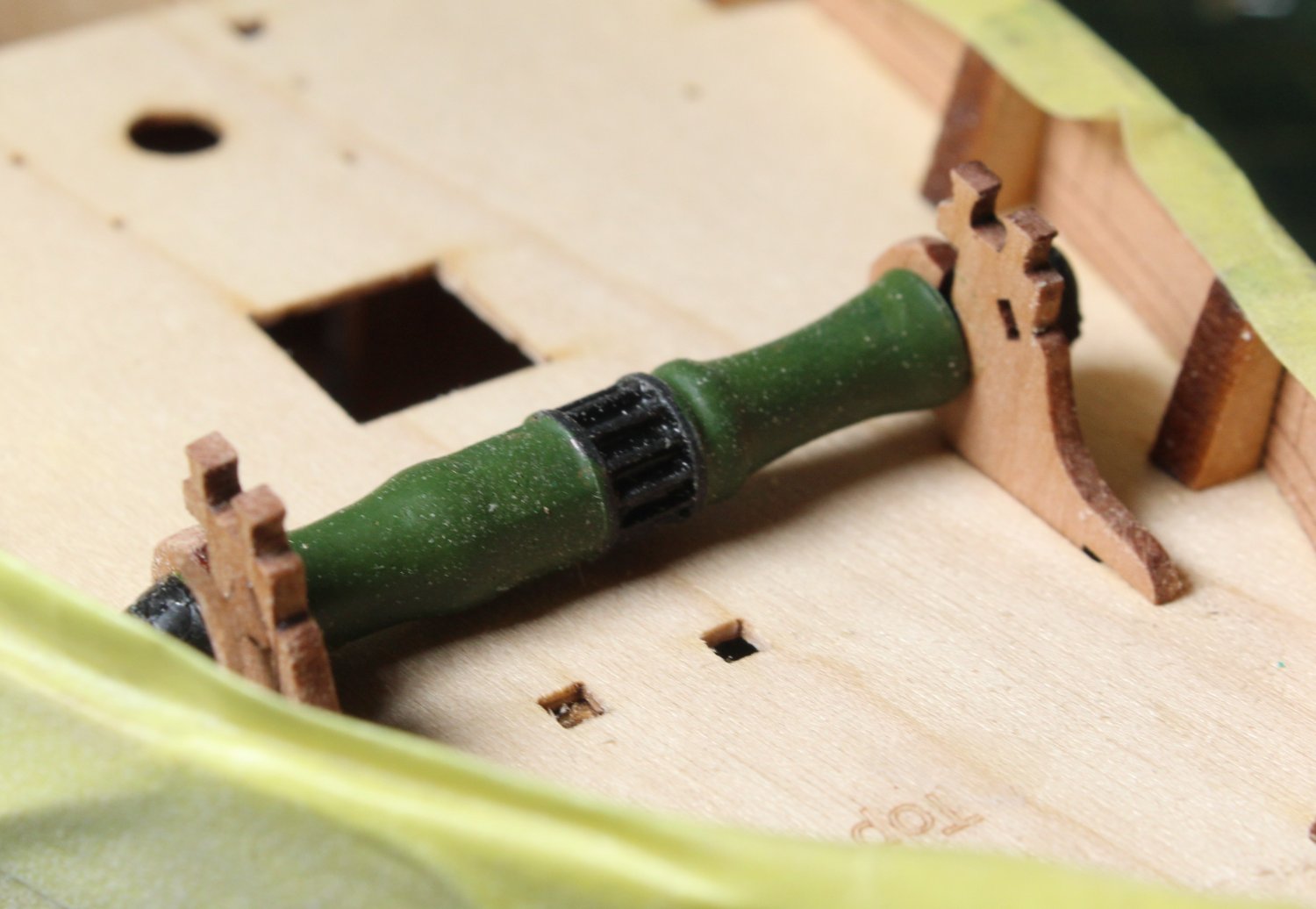
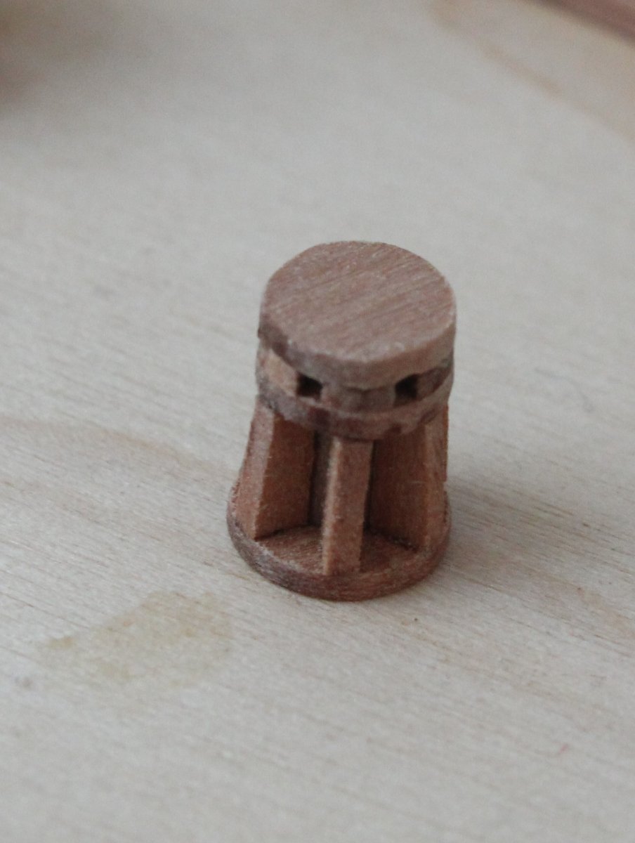
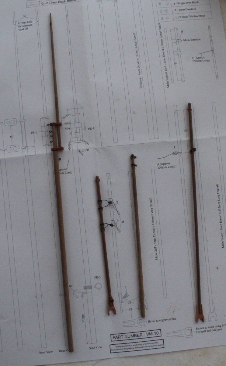
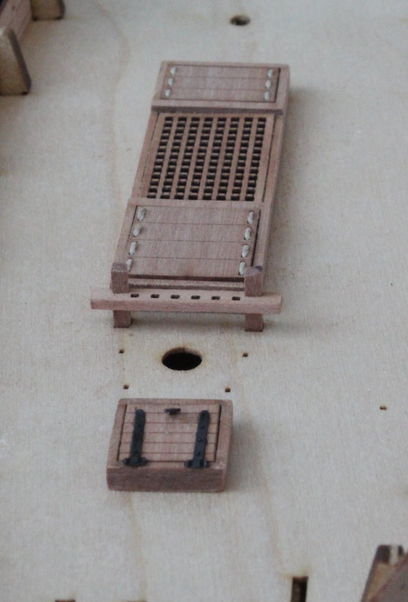
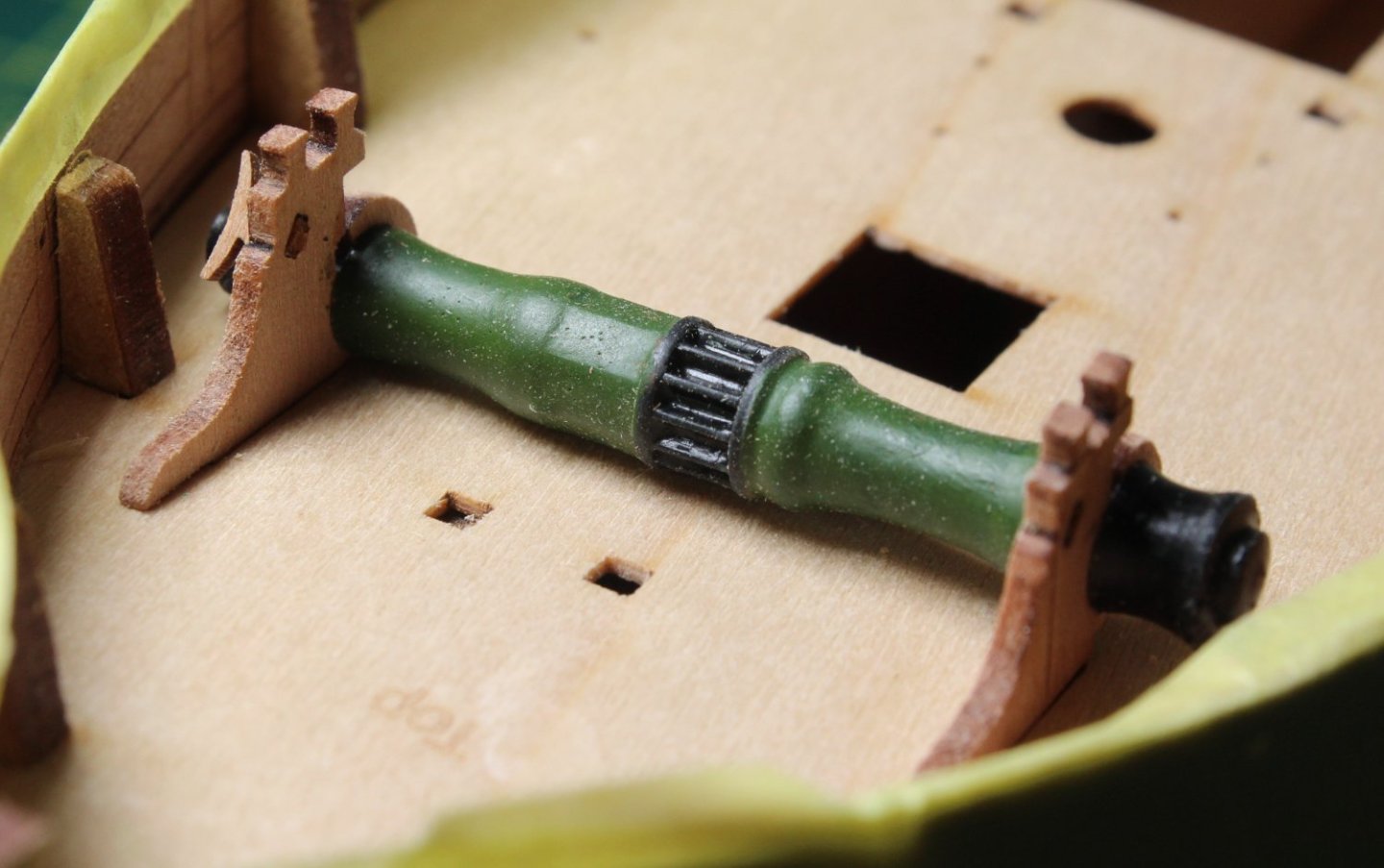
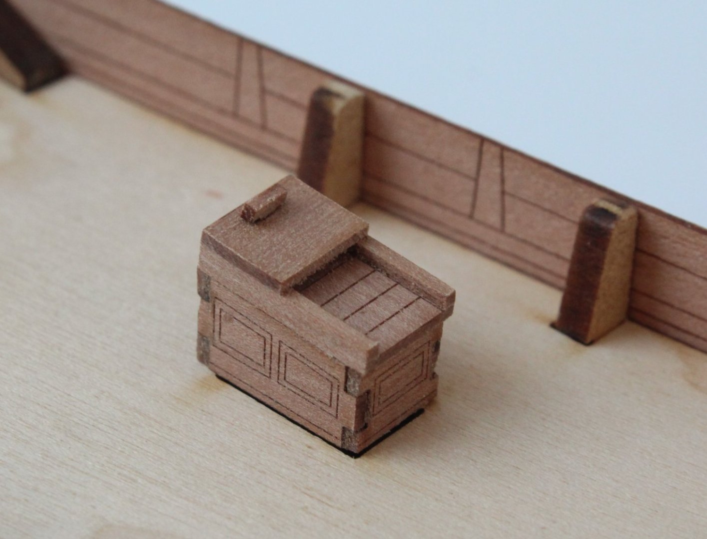
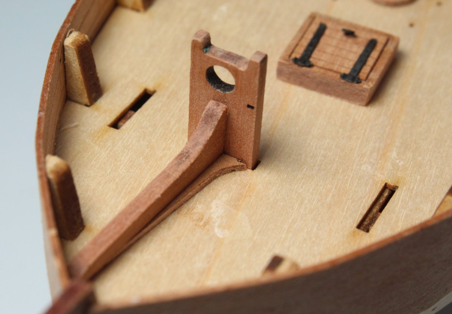
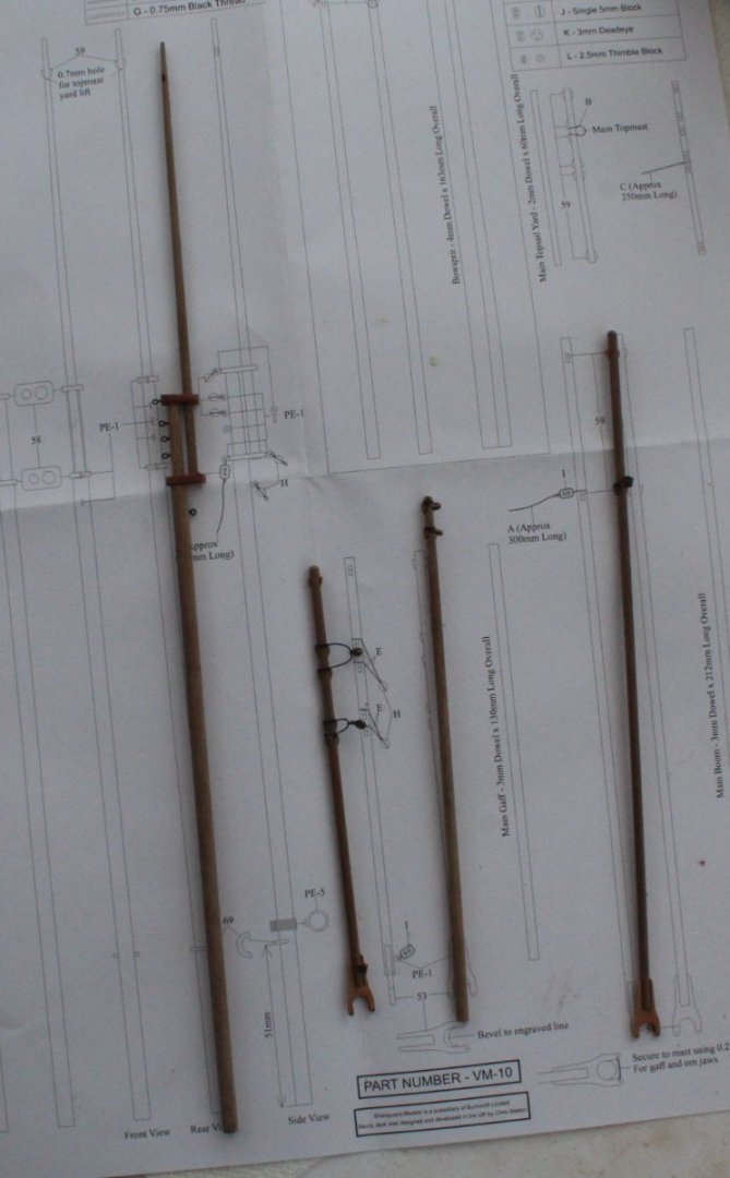
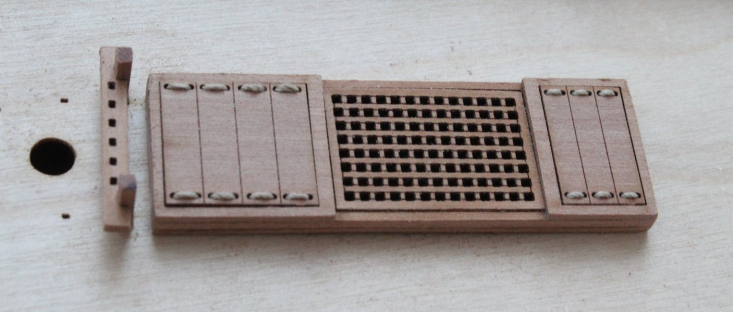
008 - Mast, Topmast, Boom, Gaff and Bowsprit As I wait for the arrival of some more Titebond Original glue the planking task has been put on hold. The Titebond should arrive later this week, as the delivery has been delayed due to the current Royal Mail postal strikes. I jumped forward in the build process and ended up making the mast, topmast, boom, gaff and bowsprit. I used my Proxxon mini lathe to shape and taper the dowels. I have added all the blocks, cleats, eyebolts and thimbles. In the photo below you will note the blocks are not shown on the mast eyebolts. I have dipped into my collection of pear blocks rather than the kit supplied blocks. I then moved on to start building some of the deck items, as can be seen in the next few photos. In the photo below I am checking the windlass side panels will fit in the deck slots, once the laser char had been removed. The resin windlass is currently being painted. I have also built the capstan, but I did not take a photo.

- 62 replies
-
- 6
-
-
- Saucy Jack
- vanguard models
- (and 3 more)
-
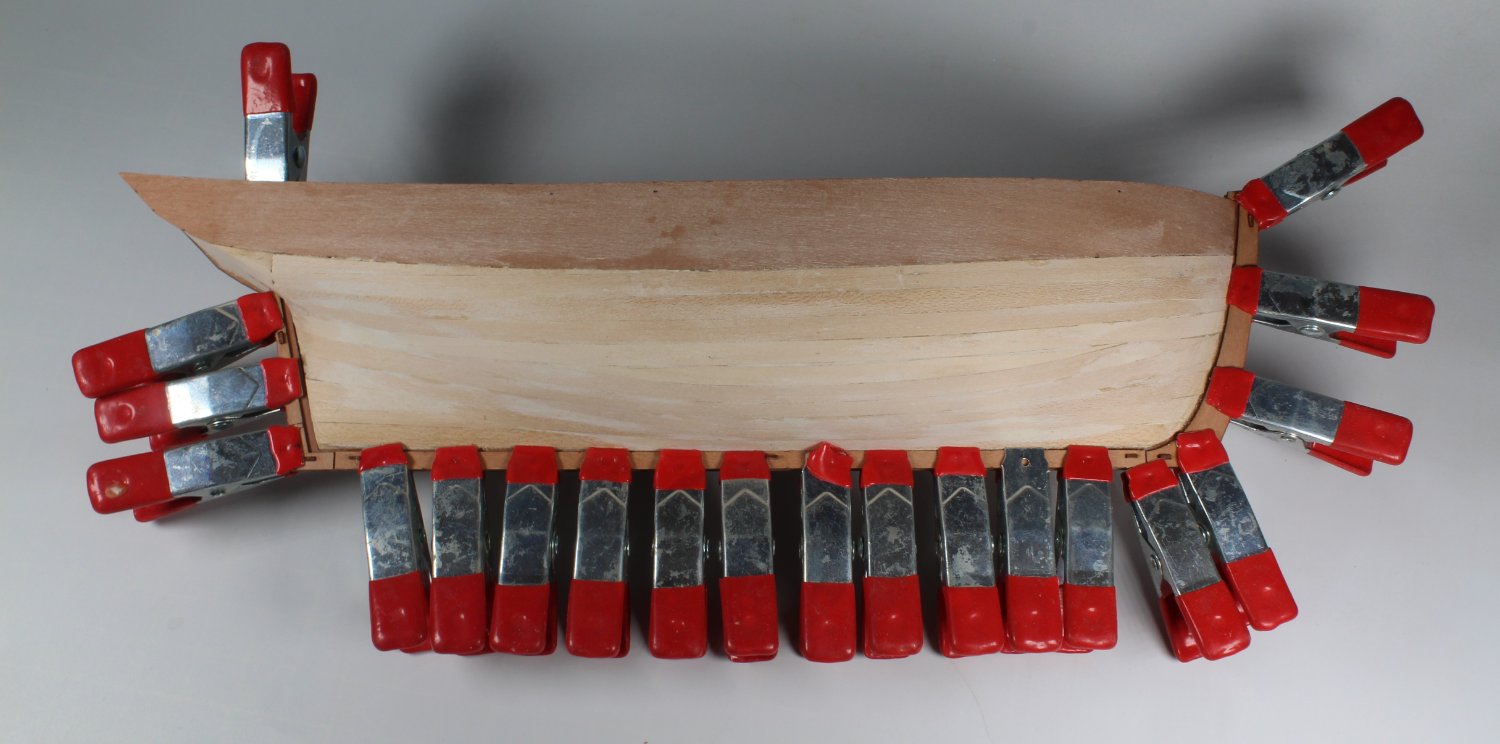
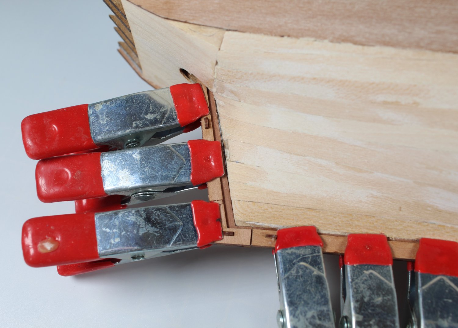
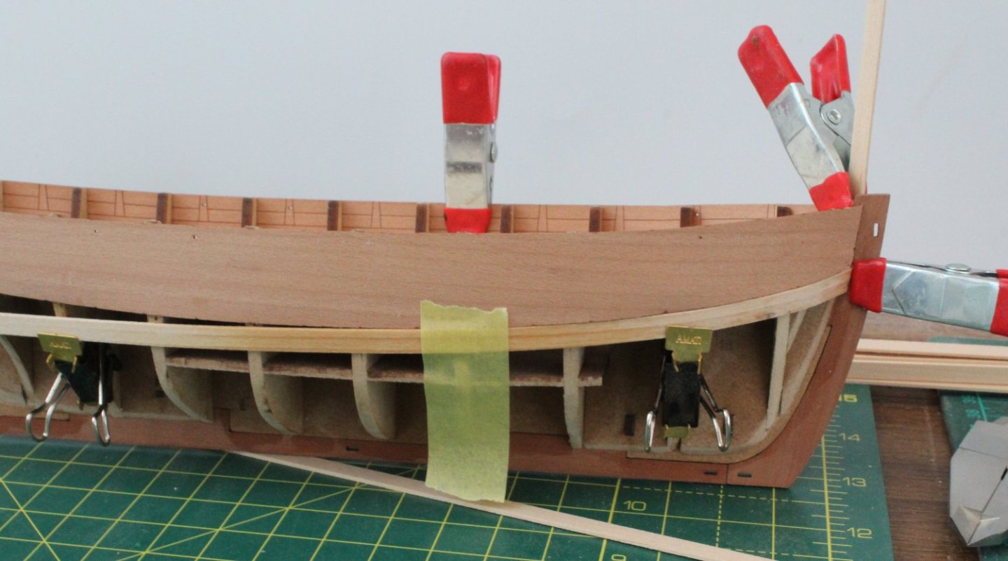
007 - 1st Planking Continues With the first plank in place I moved on to adding the next plank. Once I trimmed the both the right and left-hand planks, they were soaked in hot water for approx. 10 minutes and then bent so they followed the shape around the bow. They were then clamped in place to allow the planks to fully dry out. To continue with the planking progress, I then trimmed, soaked and bent the garboard planks. When the first plank in place I added a stealer at the stern to fill the gap.

- 62 replies
-
- 3
-
-
- Saucy Jack
- vanguard models
- (and 3 more)
-
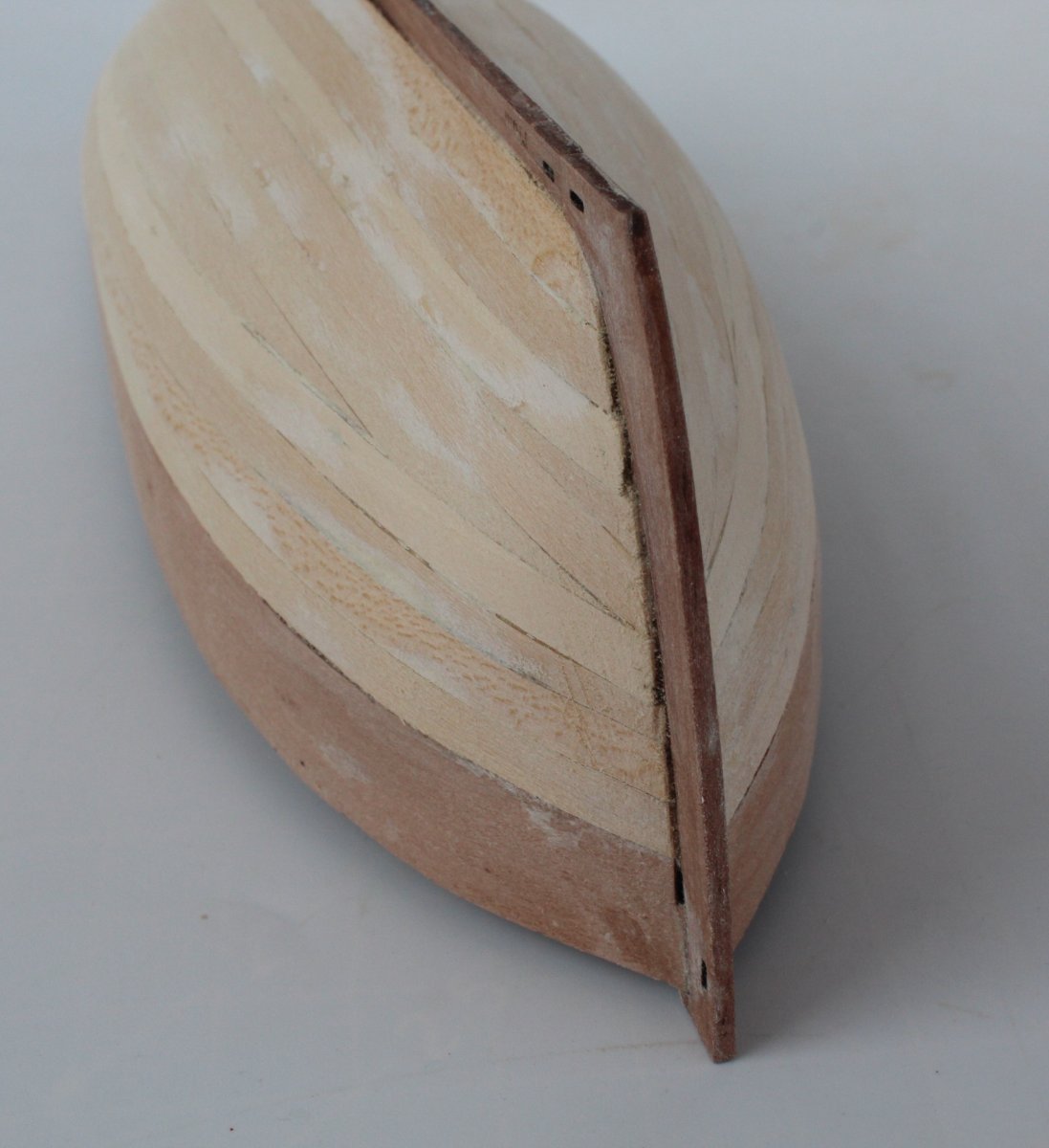
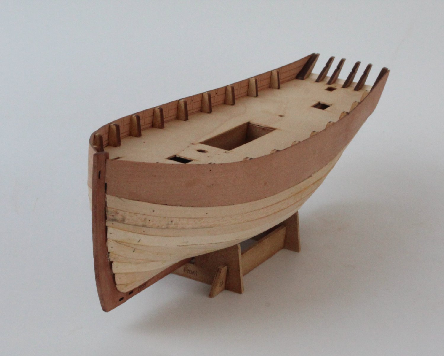
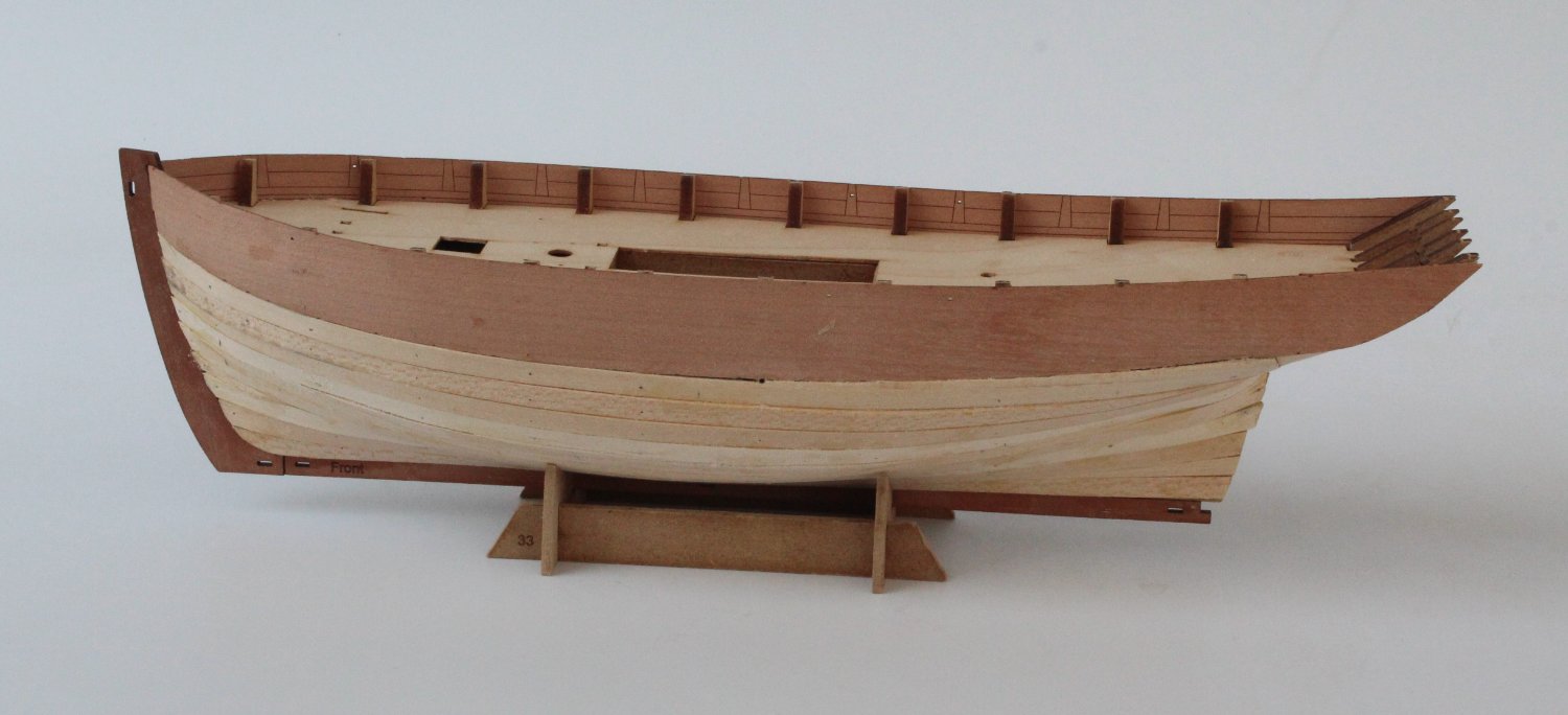
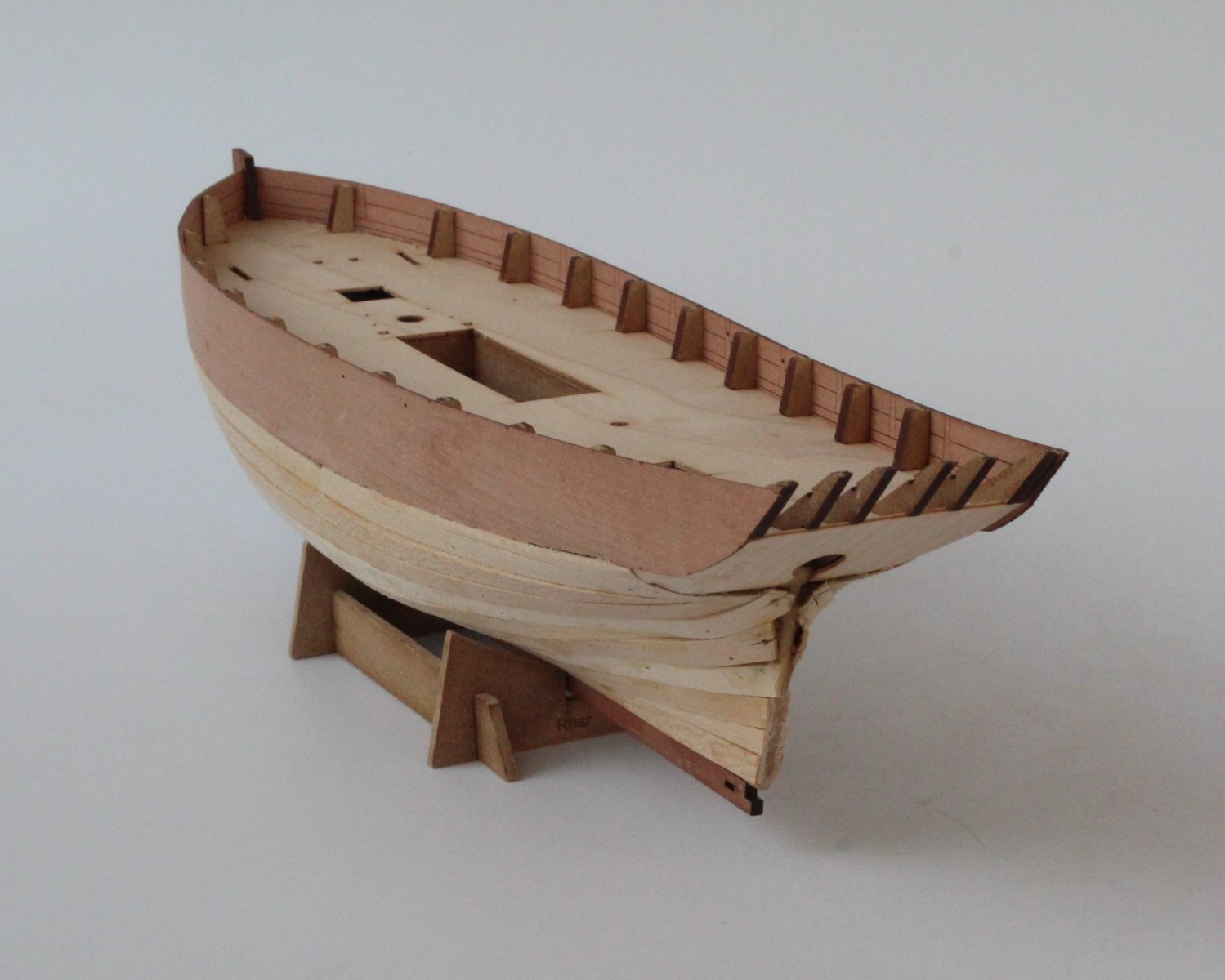
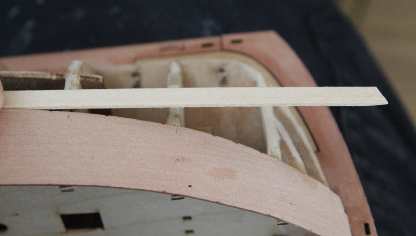
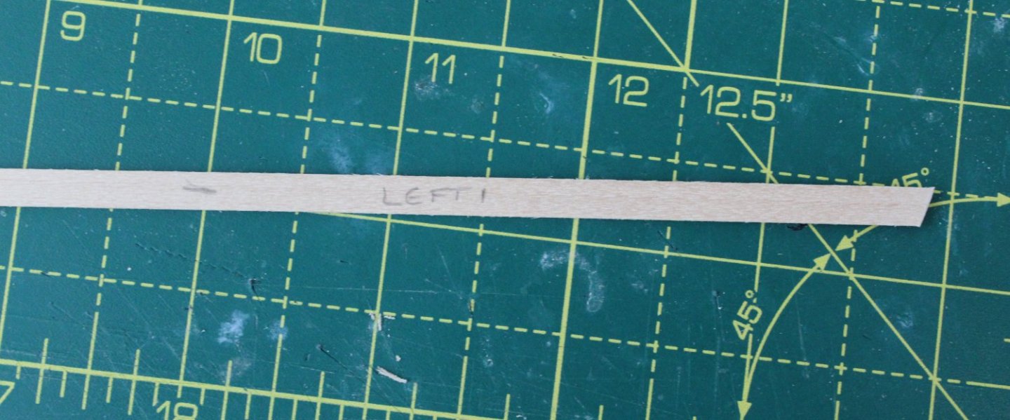
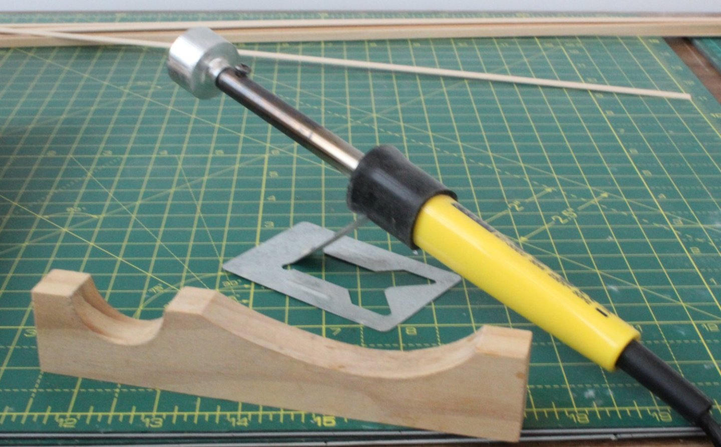
006 - Start of the First Planking Now that I completed the Erycina build I can now turn my attention to completing the Saucy Jack. I have decided that I am in no hurry to complete this build, given the timescale for the release of the Indy kit, which is my next planned build. The Saucy Jack is ready for the first planking layer. Having checked the kit supplied planks, which should be 5mmW by 1mmD I noted that quite a few of the planks were nearer 0.7mmD, and the rest seemed to be around 0.9mmD. Whilst this is not an issue with the first planking, I have decided to use some of my existing stock of planking material which does measure 1mmD. Starting with the first plank I cut an angle and then sanded a camphor to the underside of the plank edge, to match the angle at the stem post, as can be seen in the photo below. It would be better if the plank was bent to follow the curve around the bow. With the plank laying across the planks I was able to see where the plank bend should begin, as indicated in the photo below. I marked the start of the plank bend on the reverse side of the plank. The start of the bend mark can be seen on the 10-line on the photo below. I do have a planking bending tool which, by scoring the underside of the plank, creates the required bend. I have opted to use my heated plank bender tool for this project. The planks are soaked in hot water for a few minutes and then bent with the application of heat to the underside of the plank. With the bend applied to both the left and right-side top planks they were clamped to the hull to allow time to fully dry out before they are ready to be glued in place. I am more inclined to try and fit the first plank as one continuous plank rather than in two halves.
- 62 replies
-
- 7
-
-
- Saucy Jack
- vanguard models
- (and 3 more)
-
Many thanks Andrew
-
Thanks. I opted for building two fishing boats as a stop gap before my next major build which will probably be the Indy. Next up will be completing the Saucy Jack.
-
Many thanks Jonathan. I have learnt so much from other members build logs so I pleased you've found my build log helpful.
-
Thank you Chris, it was a very nice model to build.
-
Thanks James, your support and help was greatly appreciated.
-
Thanks Derek. It is my first model with sails. I think they look good on a small model like the Erycina.
-
Many thanks Dan. I found belaying the rigging, after the sails had been fitted, the trickiest aspect of this build due to the limited access.
-
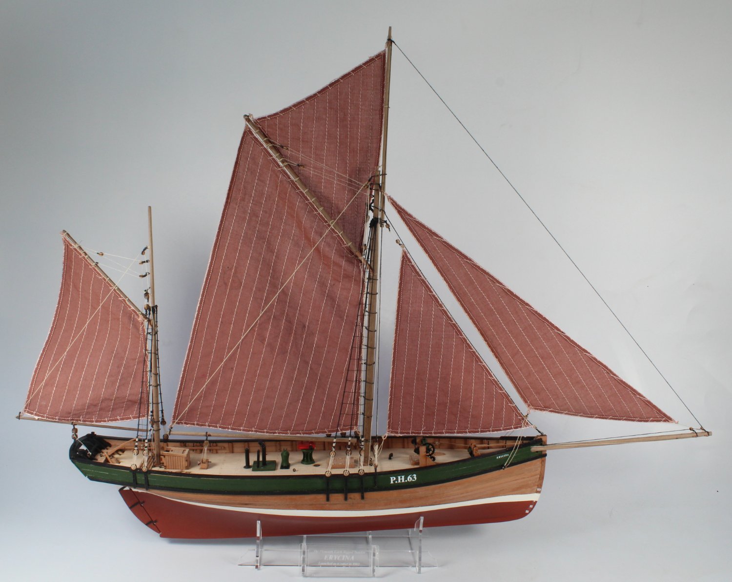
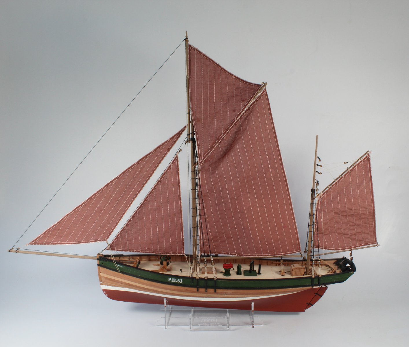
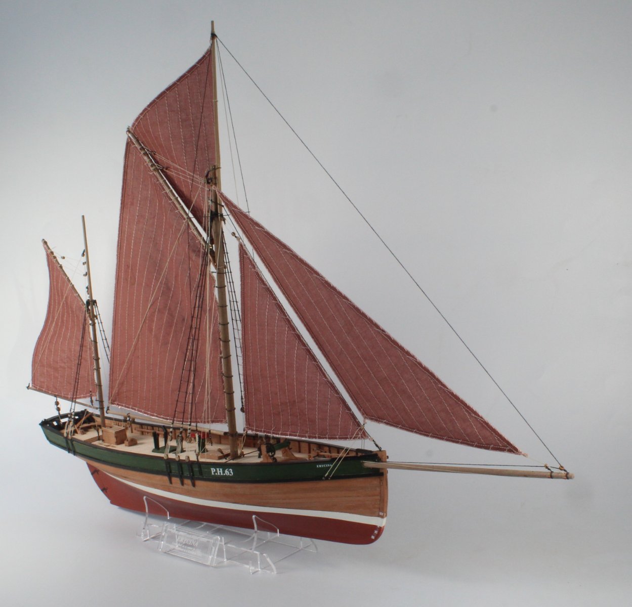
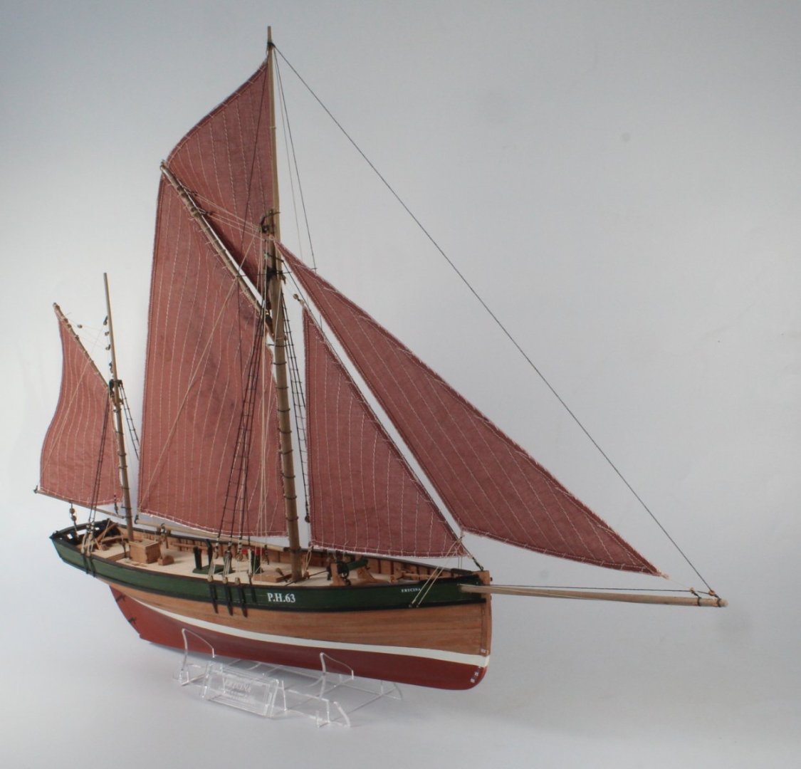
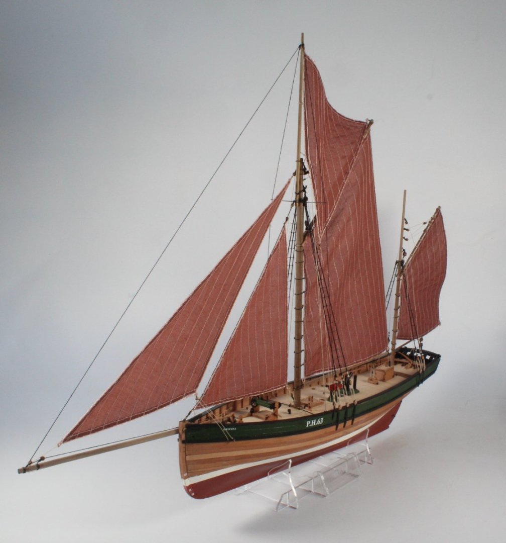
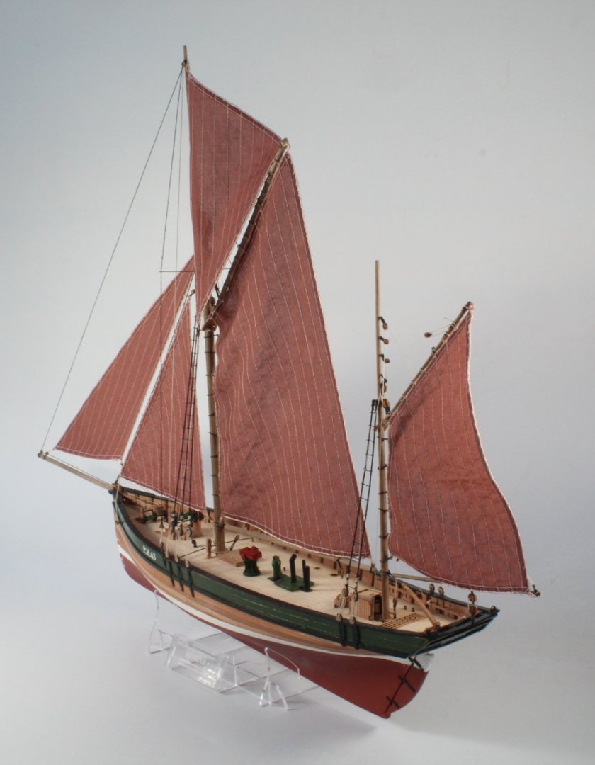
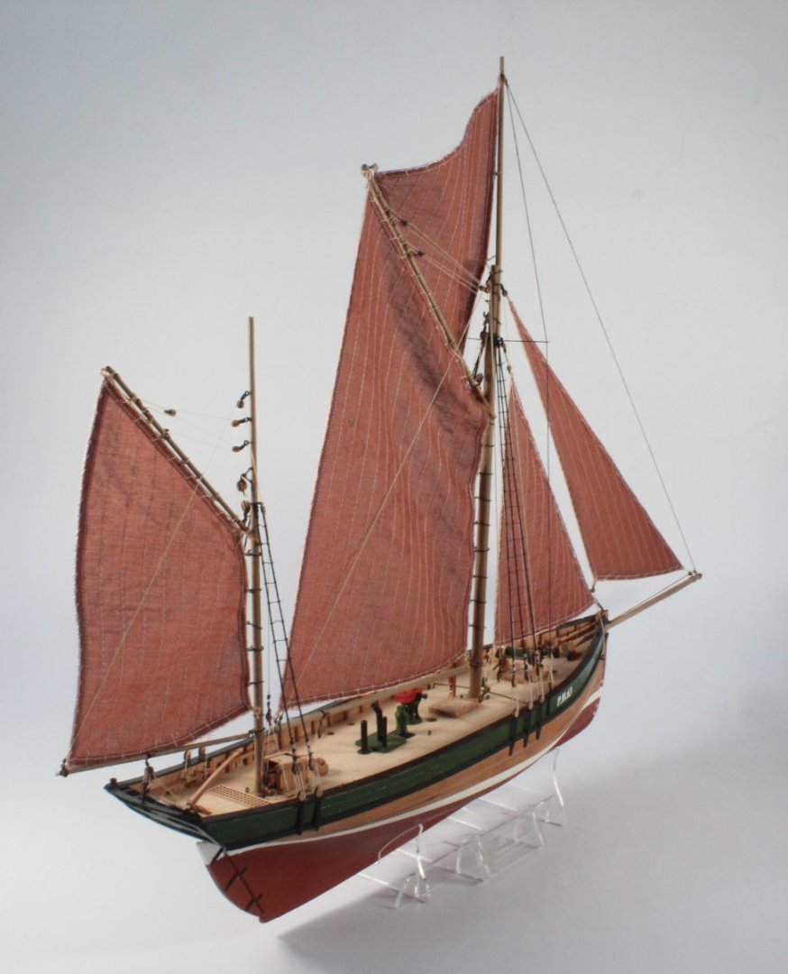
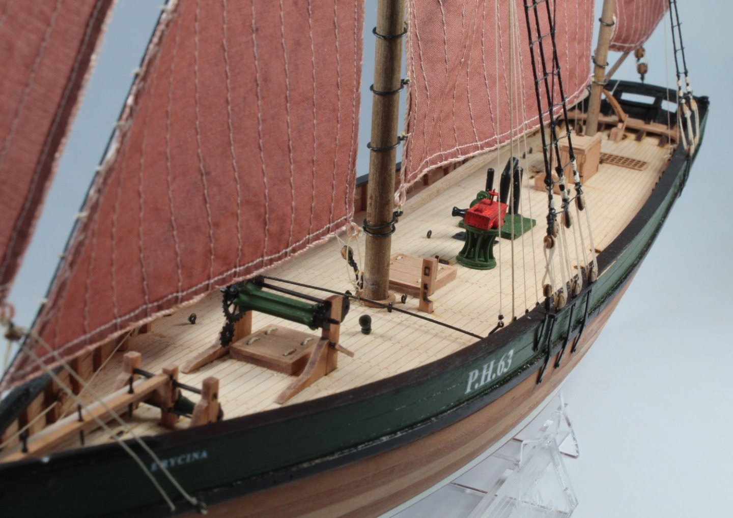
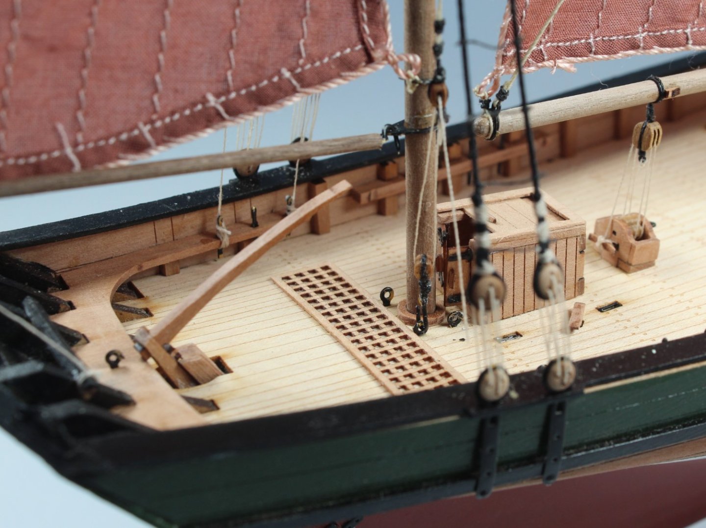
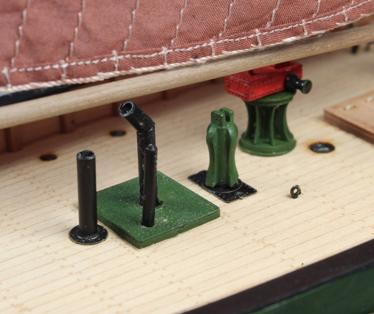
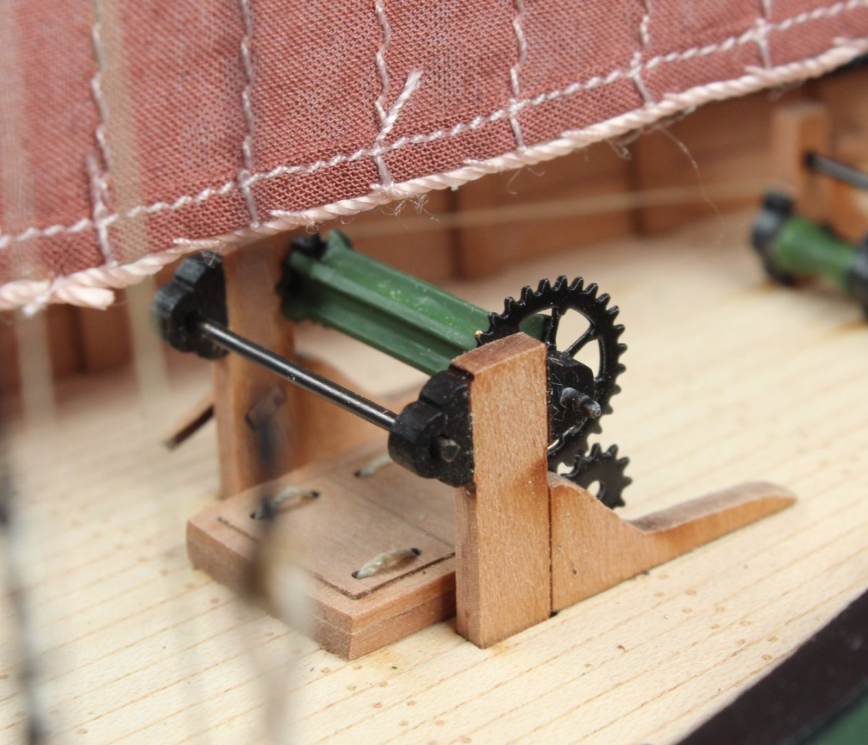
041 - Completed Model I have now built the display stand and the model is now complete. This has been an interesting and fun model to build. @chris watton design work is outstanding and the kit instruction manual, plan sheets and materials are of the finest quality. I have attached a selection of photographs of the completed model for your viewing pleasure.


- 106 replies
-
- 13
-

-
-
- Erycina
- Plymouth Trawler
- (and 3 more)
-
Many thanks Derek. I have learnt so much from following your build logs.
-
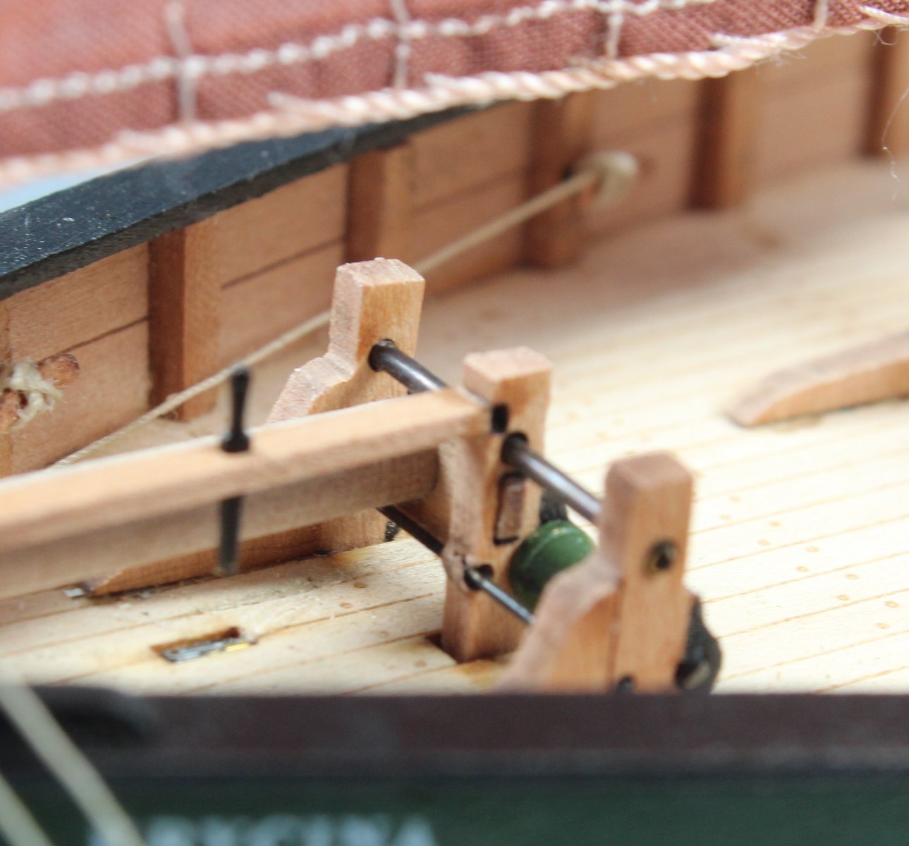
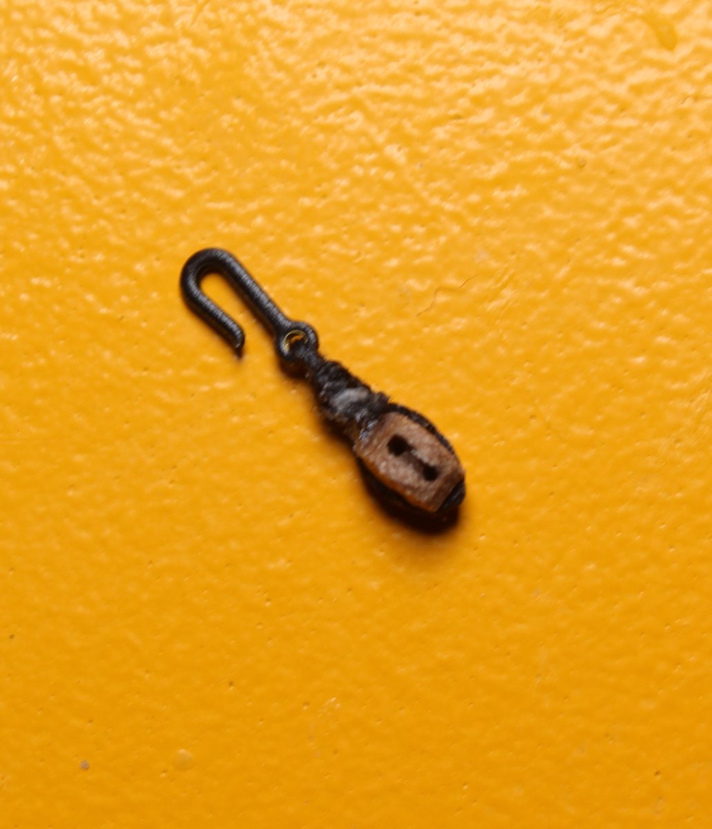
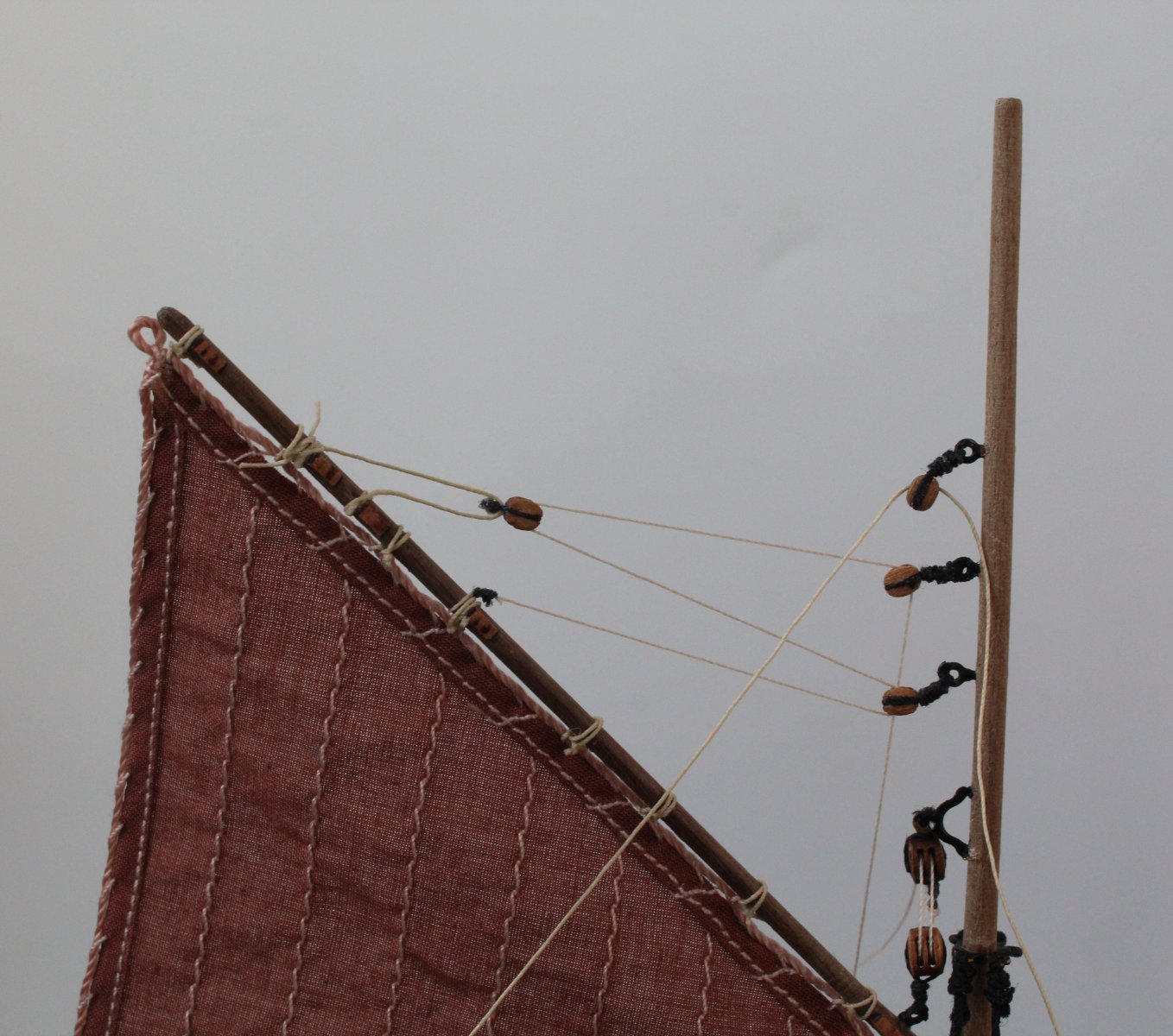
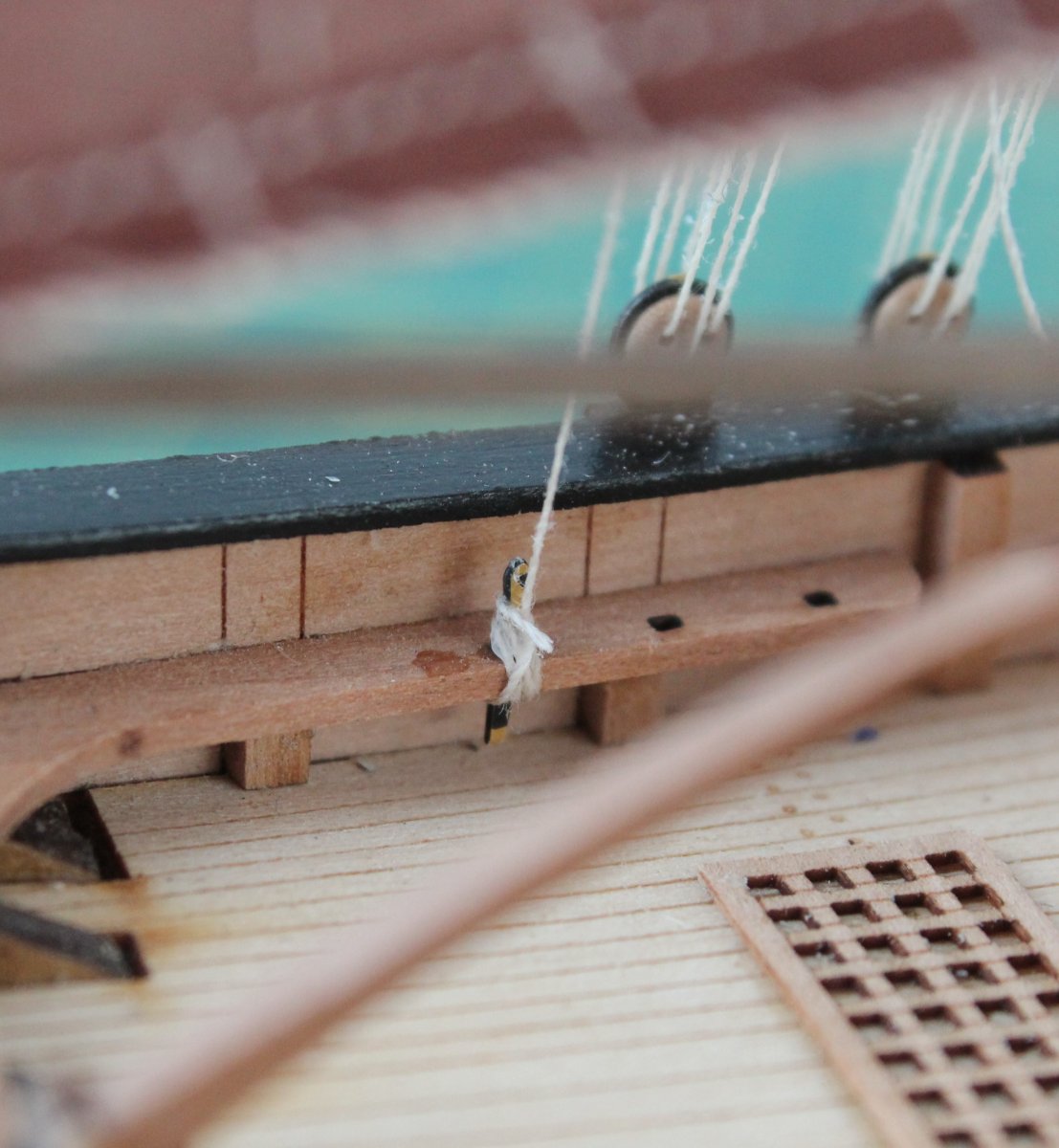
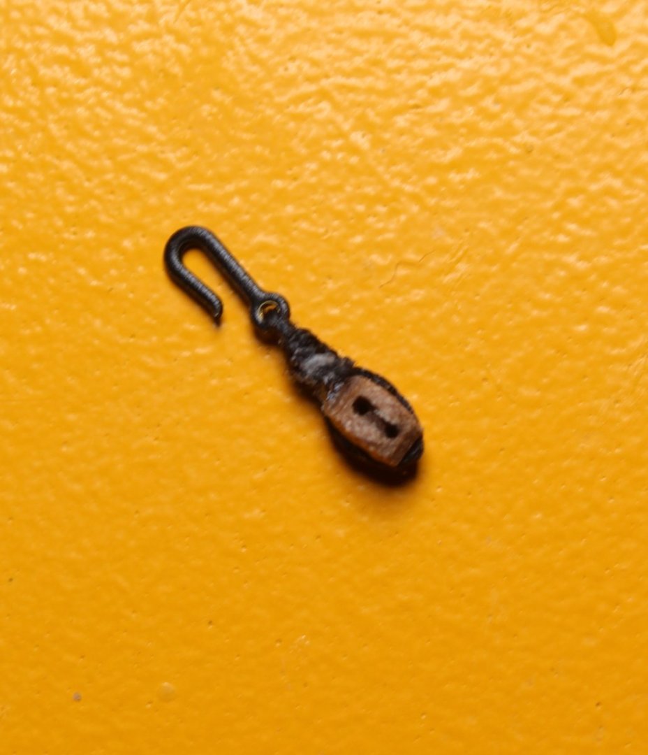
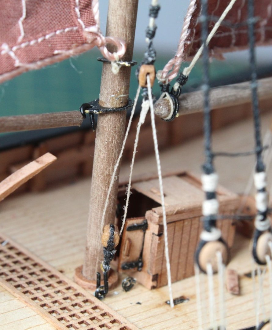
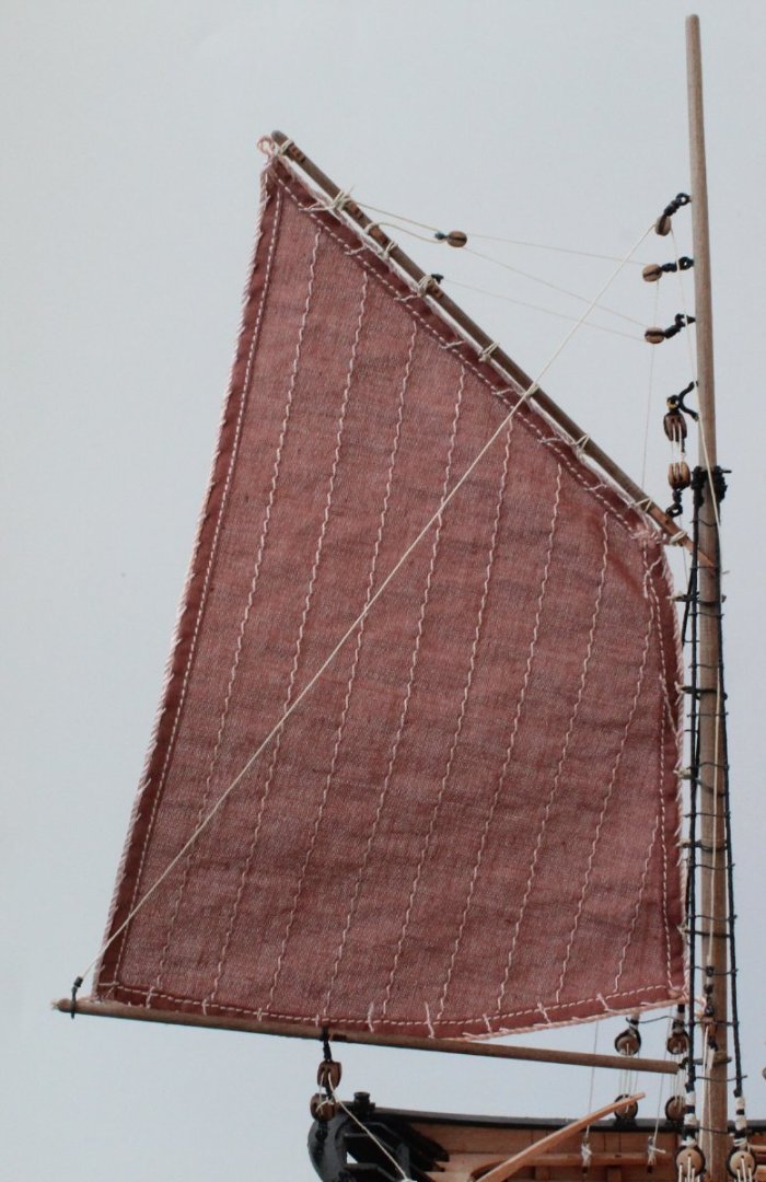
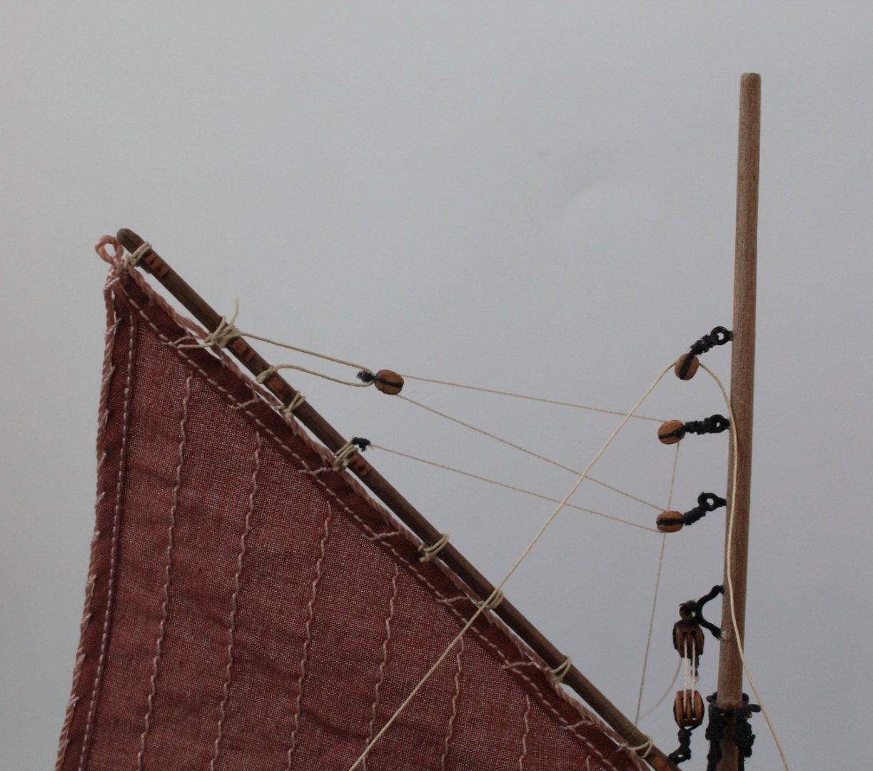
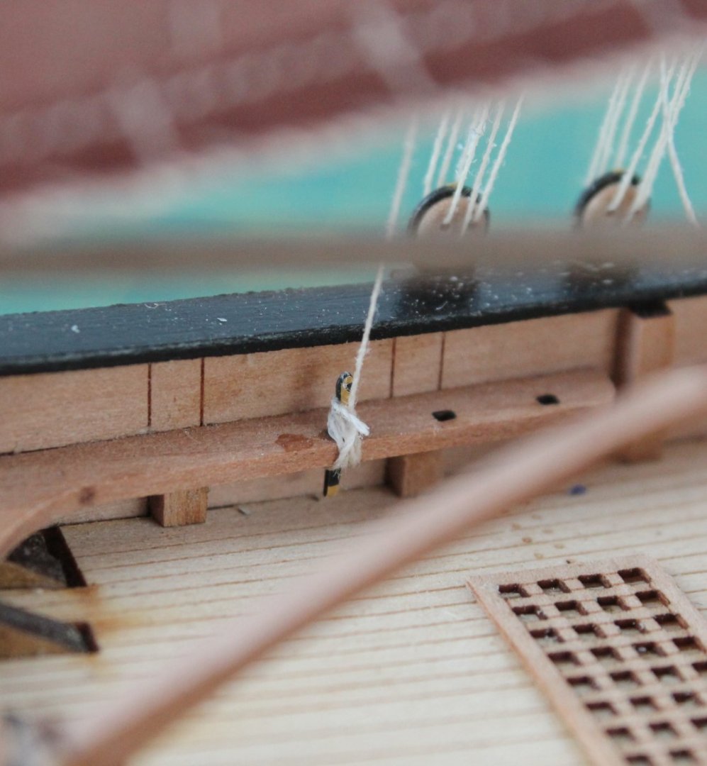
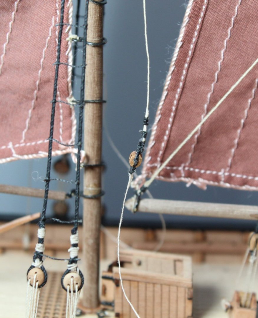
040 - Mizzen Sail Rigging T The end is in sight as I'm working on the mizzen sail and associated rigging which is the final boat building task. The first photo shows the rigging of the mizzen gaff block to the two lower mizzen mast blocks. The thread from the end of the mizzen boom can also be seen being fed through the top mizzen mast block. The mizzen gaff lift rigging (the two 4mm double block can also be seen). The next photo shows the mizzen gaff block rigging belayed. The thread from end of the mizzen boom is belayed via a double block arrangement, with one end secured to a deck eyebolt, via a hook. The other end is taken to a belaying pin. In the photo below I have added a 3mm single block to the end of the boom rigging. The next photo shows the other 3mm single block complete with the hook. The next photo shows the completed double block in situ. The final task was to belay the mizzen gaff lift thread to a belay pin. WIth that done all work on the mizzen sail was complete. The final task on this build is to assemble the display stand.
- 106 replies
-
- 6
-
-
- Erycina
- Plymouth Trawler
- (and 3 more)