HOLIDAY DONATION DRIVE - SUPPORT MSW - DO YOUR PART TO KEEP THIS GREAT FORUM GOING! (Only 27 donations so far out of 49,000 members - C'mon guys!)
×


Glenn-UK
-
Posts
3,156 -
Joined
-
Last visited
Content Type
Profiles
Forums
Gallery
Events
Everything posted by Glenn-UK
-
 No matter how clamps I have I always seem to be one short😂
 -
You've caught me up and will soon be well ahead of me. My first planking will be very slow and steady
-
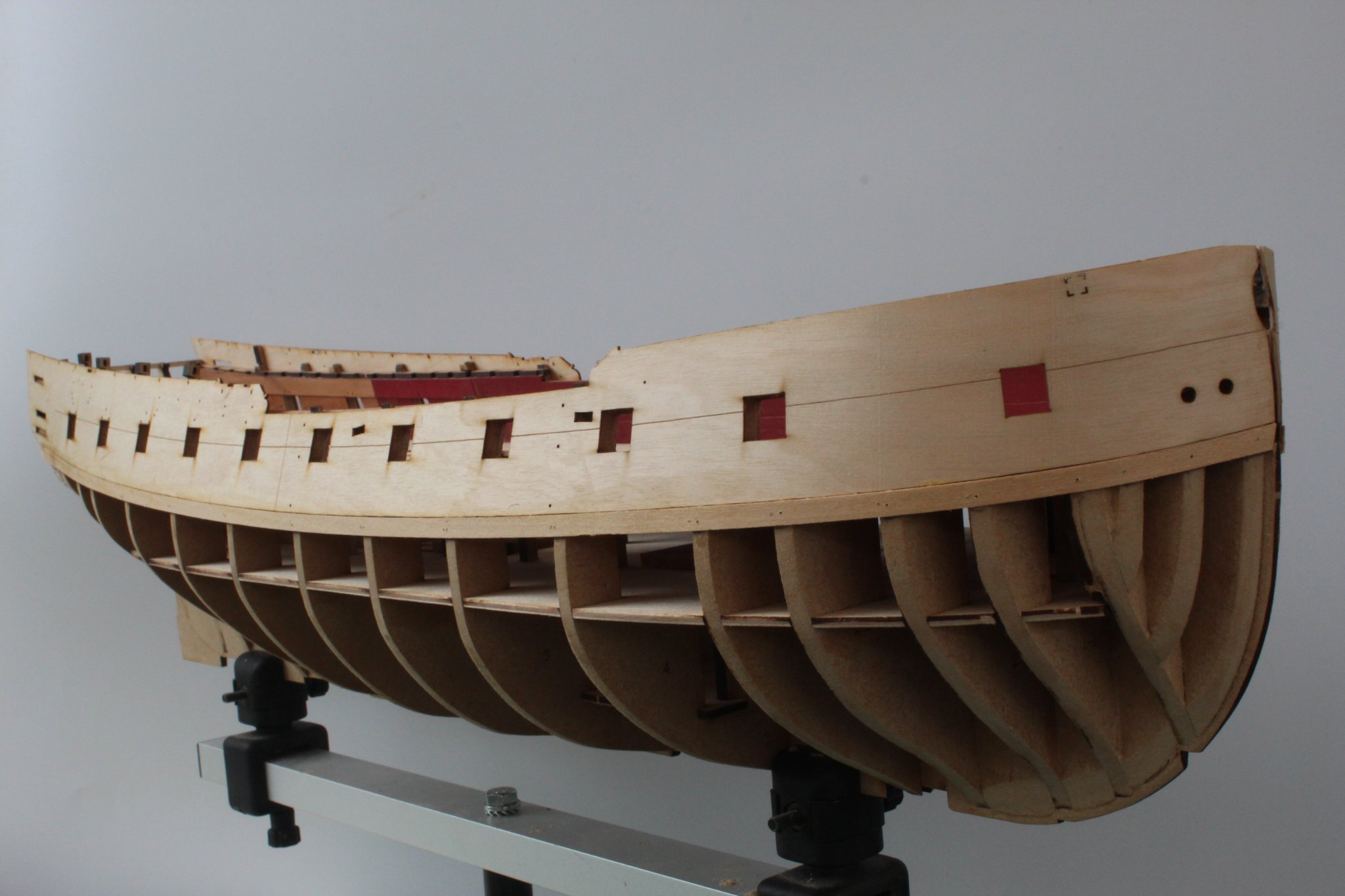
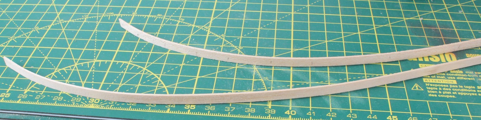
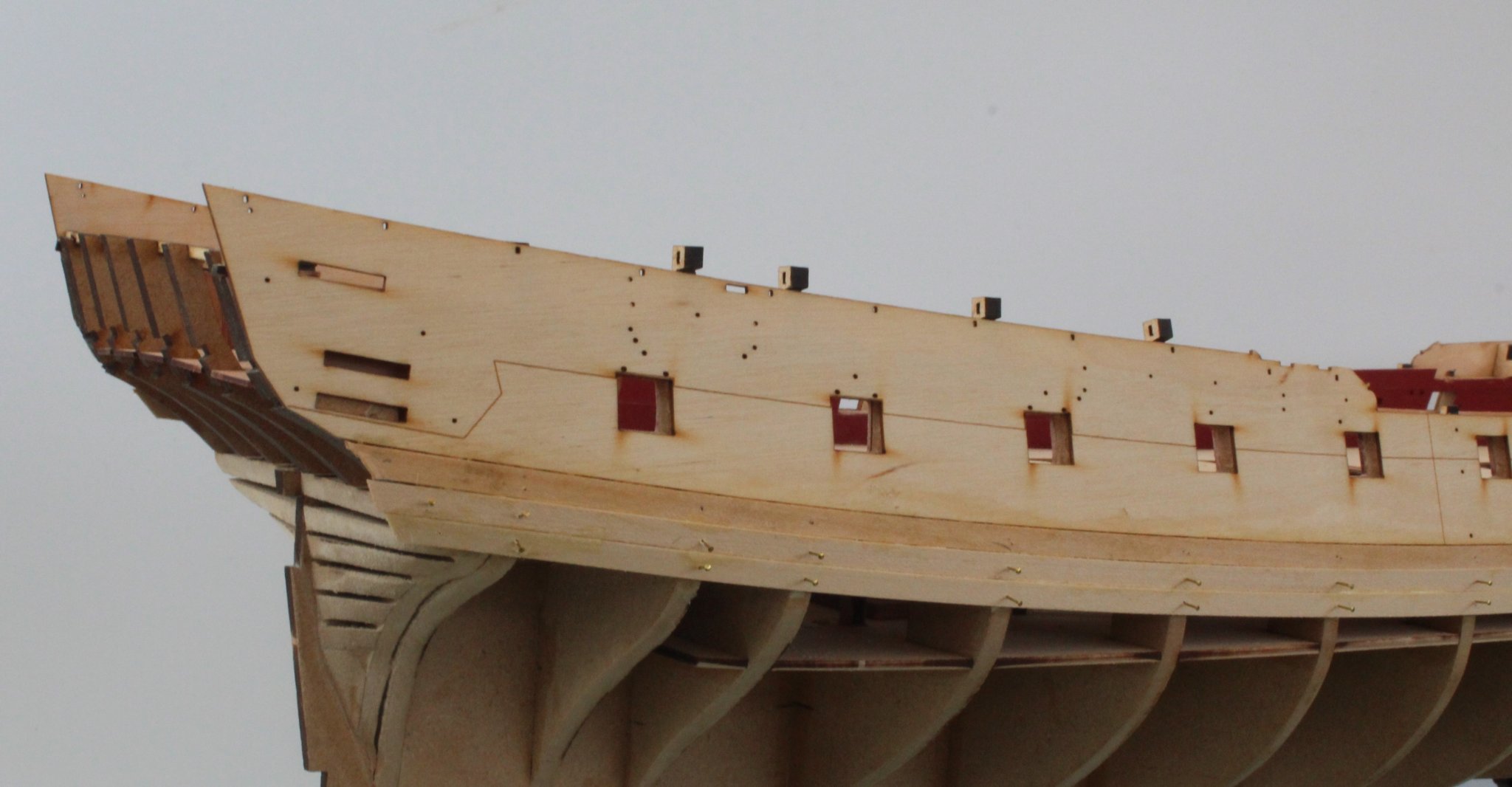
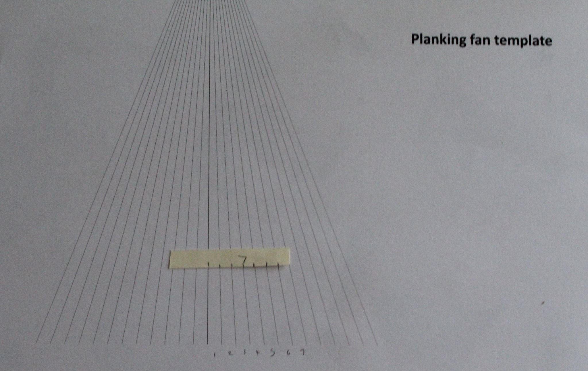
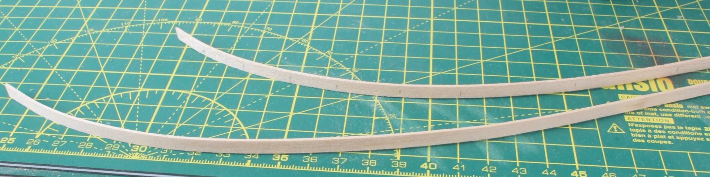
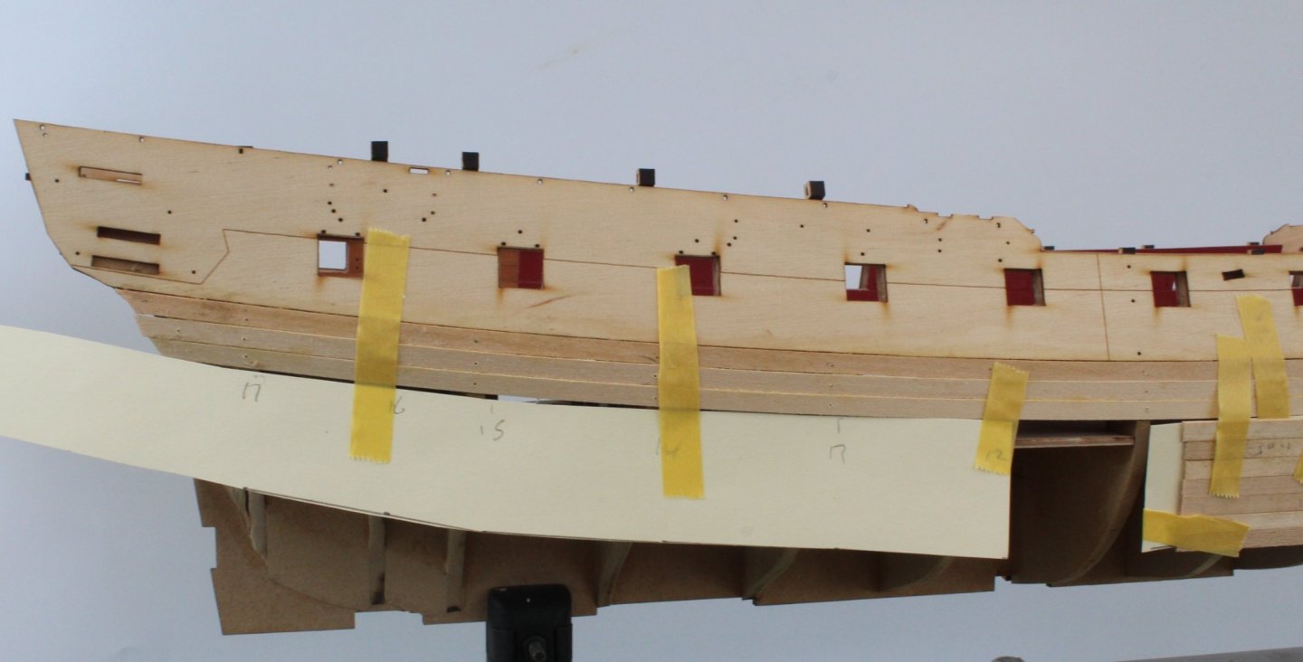
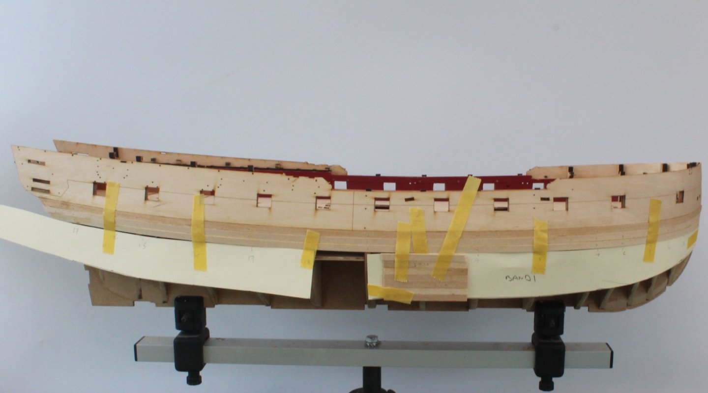
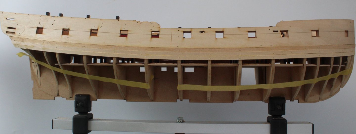
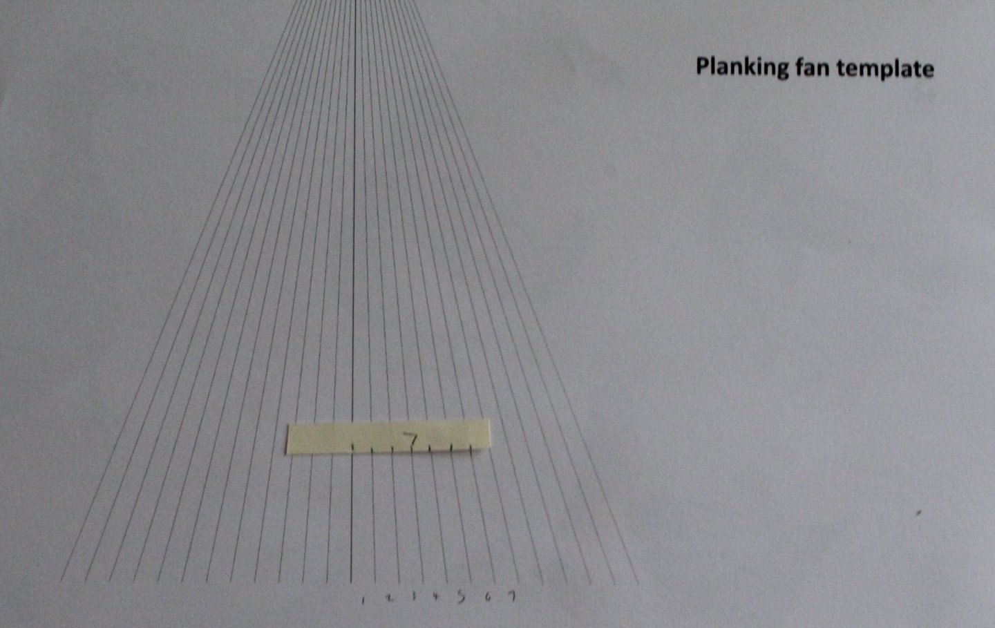
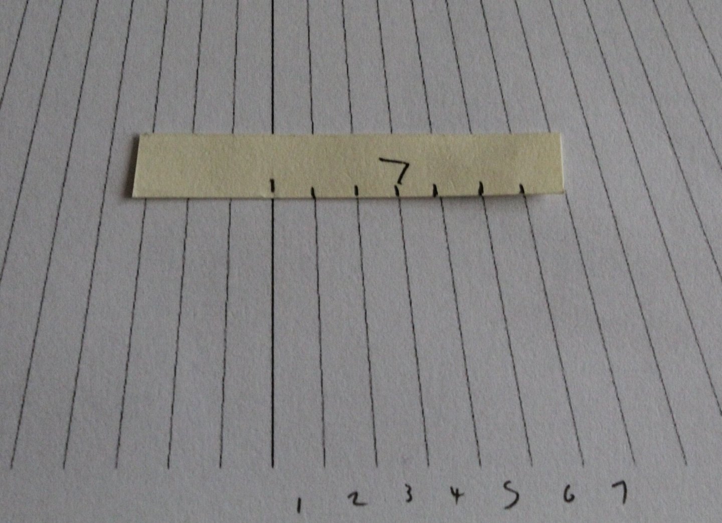
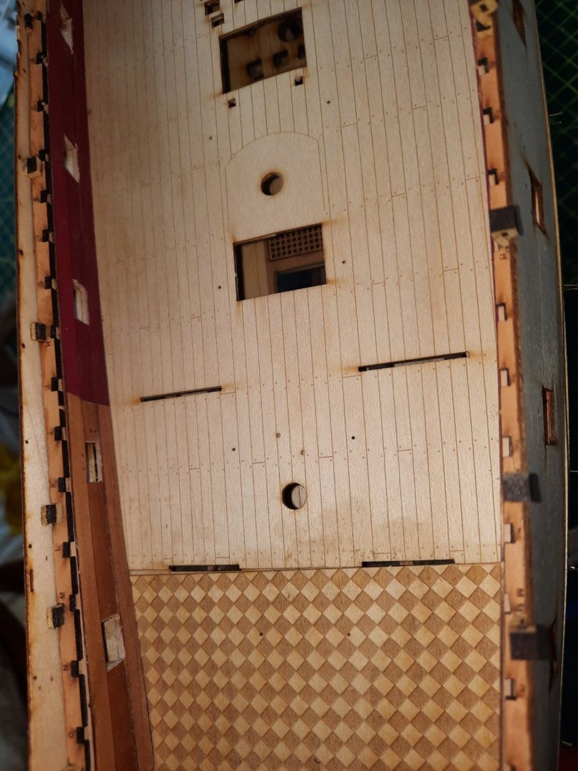
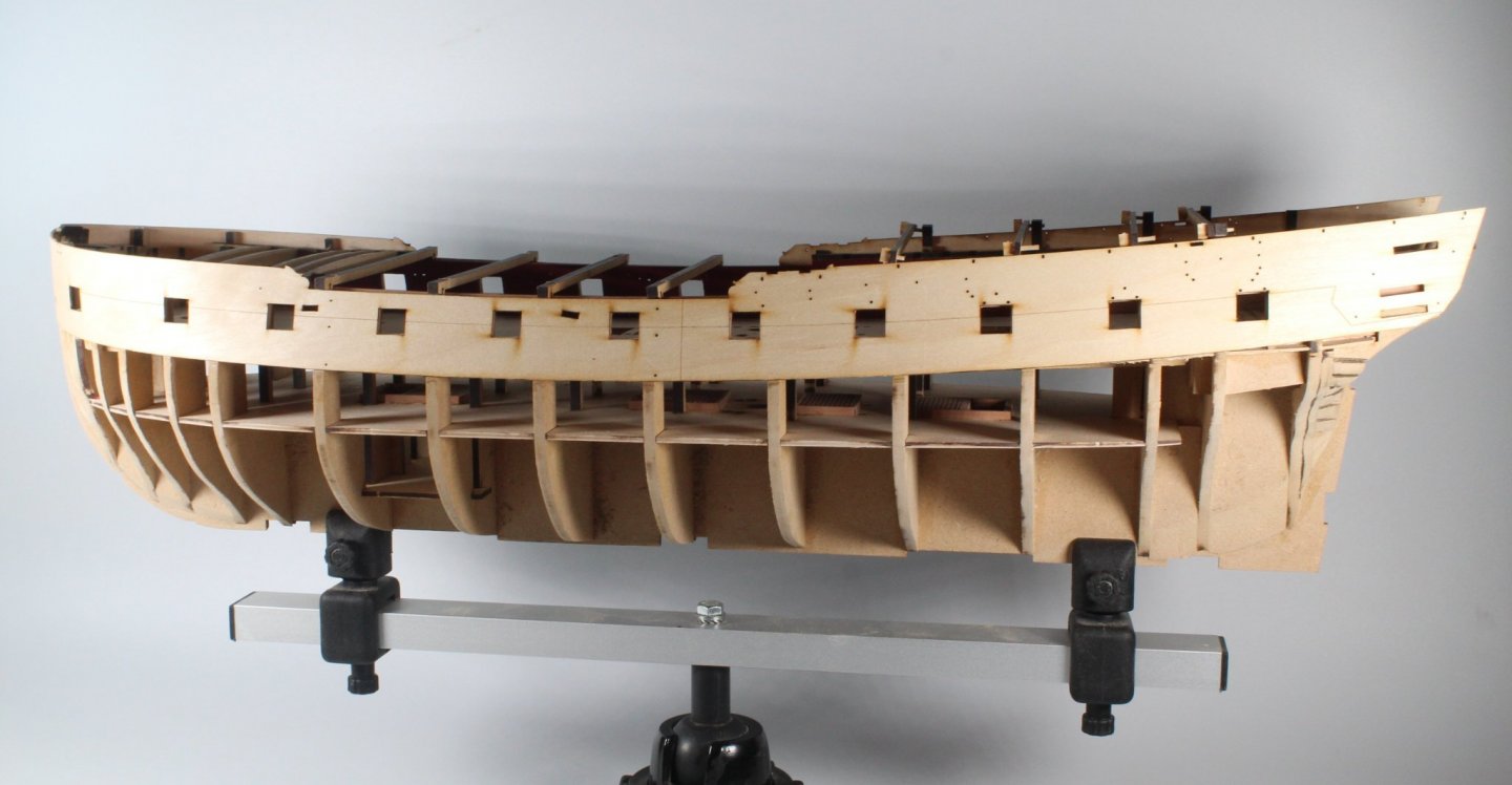
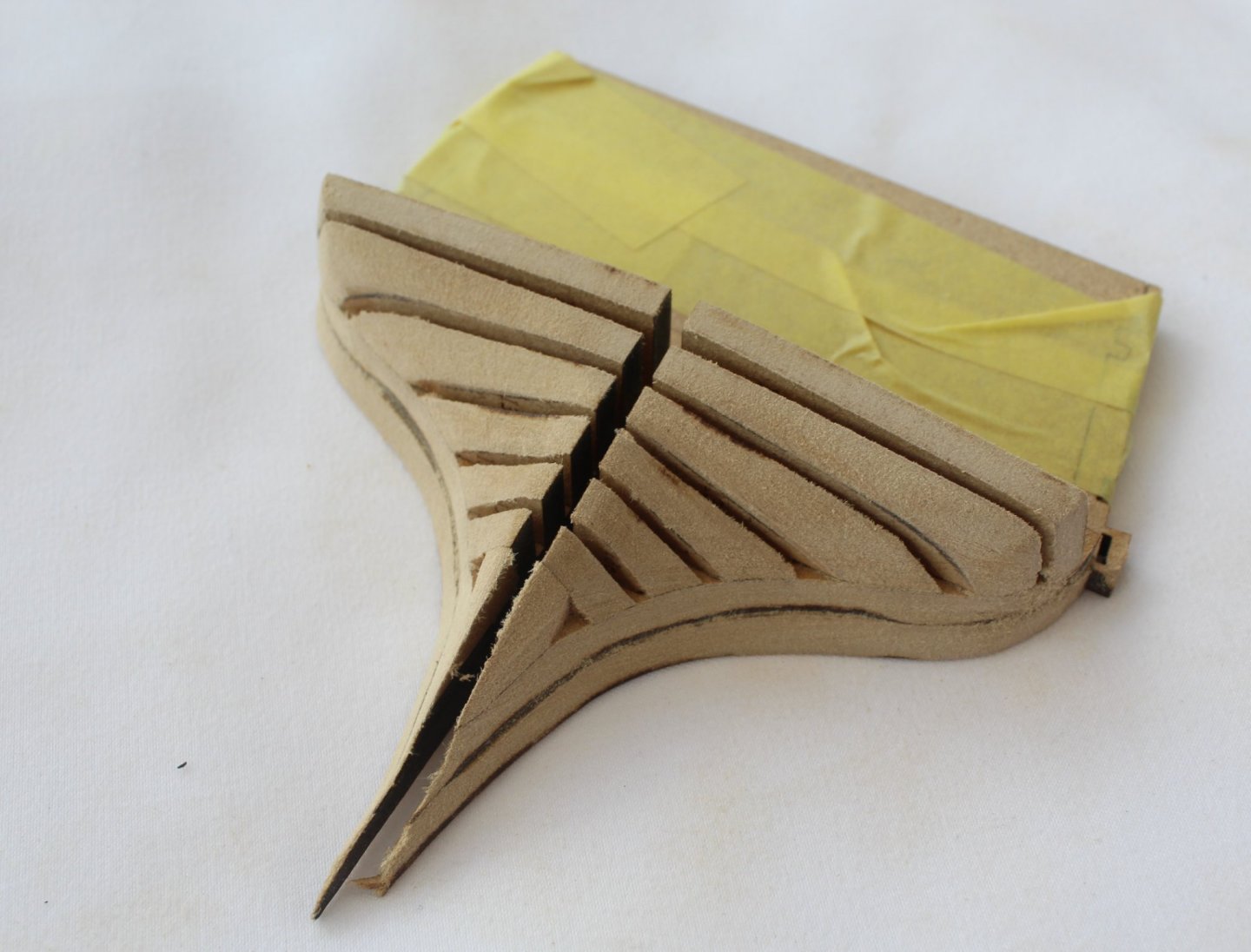
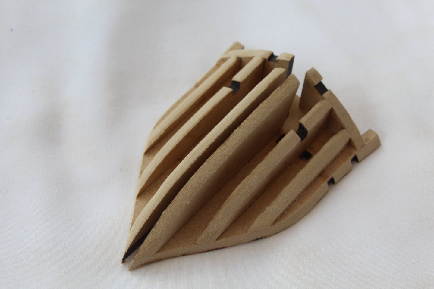
HULL ASSEMBLY FIRST PLANKING – PART 1 BUILD MANUAL STEP 138 LINK TO MY BUILD LOG INDEX Tools Used Titebond original glue Old paint brush Heated planking bender Gathering the materials required The following kit parts are required for this section of the build: F-43 (1mm x 5mm limewood strips) Brass pins Assembly Process – First Three Planks The build manual indicated the first three planks could be fitted without any tapering so I decided to go ahead and fit the first three planks. This is a picture after the first plank had been glued in place. I decided, after fitting the first plank, that it would be better to bend the planks around the bow section. I soaked the planks in warm water for about 10 minutes and then applied the required bend using my heated plank bender. Picture of the next two planks ready to be fitted. The planks were then fitted without any problems. I am glad I spent time sorting the planks widths, as per my earlier post. Assembly Process – Banding Process I have read and watched videos on planking where the hull is split into bands. I have never tried this method before but thought it would be worth trying on this build. With reference to the attached pdf file. Banding.pdf I had already measured the length of each bulkhead prior to fitting the first three planks so I made the necessary adjustment. I calculated that I would need 20 planks at the widest section, so decided that I would have three planking bands, 2 bands would be 7 planks wide and the third band would be 6 planks wide. The spreadsheet provided me with the required plank widths at the different bulkhead positions. as can be seen in the attached pdf file I then tweaked these calculations so the banding lengths would be easier to measure. I transferred the band 1 dimensions to a sheet of card and cut out the required shape for the bow and stern. I also glued 7 small lengths of planks to double check the maximum band width. I taped these patterns to the hull and marked the lower edge on the bulkheads. The patterns were then removed and I added a banding line using some tape, using the pencil marks as a guide. I have now started to mark up the tick strip, for each bulkhead position, using a planking fan template. This concludes the progress to date. In the next stage I will transfer the tick marks to the next 7 planks so they can be added to the hull. I will also add the lateral edge bends so the planks will lay flat around the bow shaping. I may split each plank into two pieces with a midship join.


-
Nice work, looking very nice. I have just started the 1st planking
-
I have no ears of the left hand side but they are all in tact on the right hand side. I did glue the broken ears back in place before the hull pattern was fitted but they have since decided to depart the Sphinx.

-
Looking good, it takes quite a bit of effort.
-
Nice work, as always
-
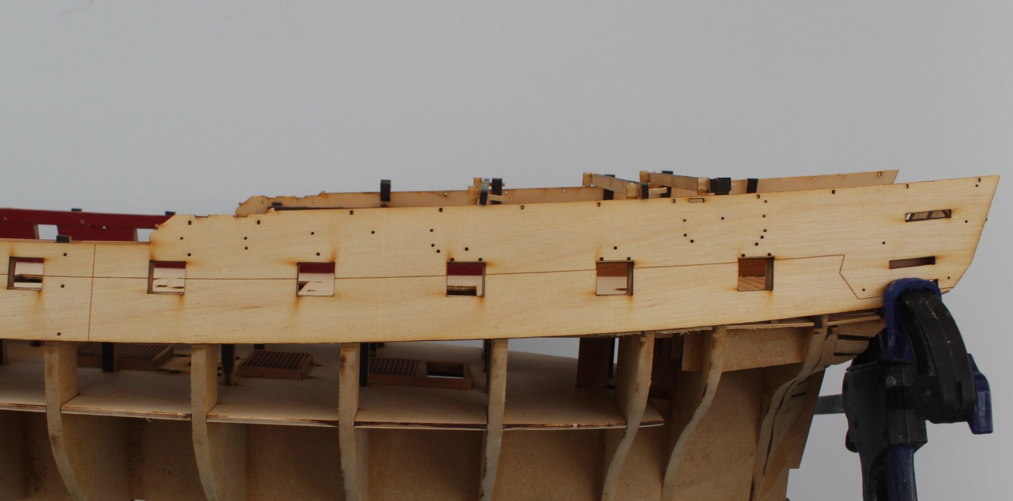
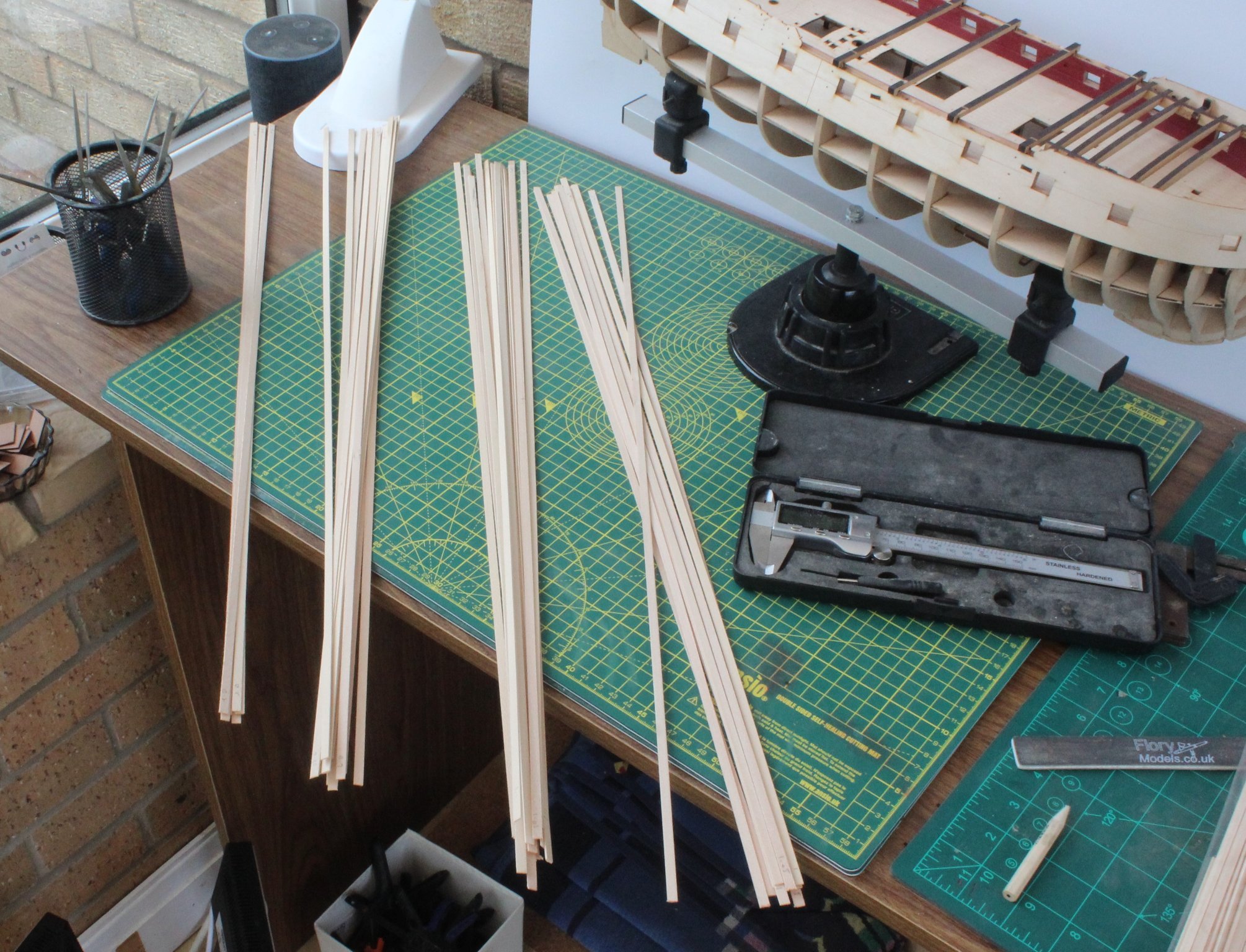
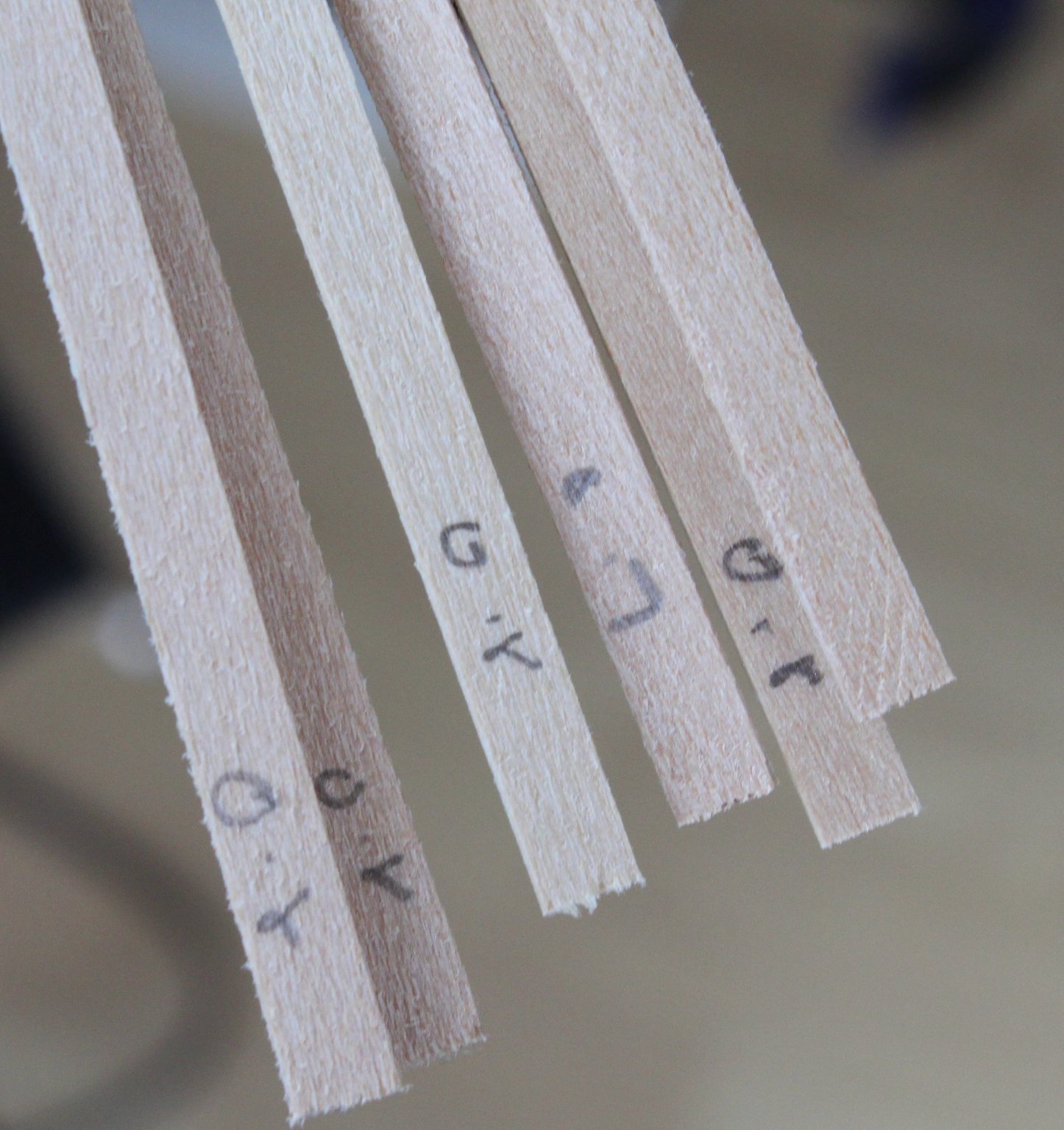
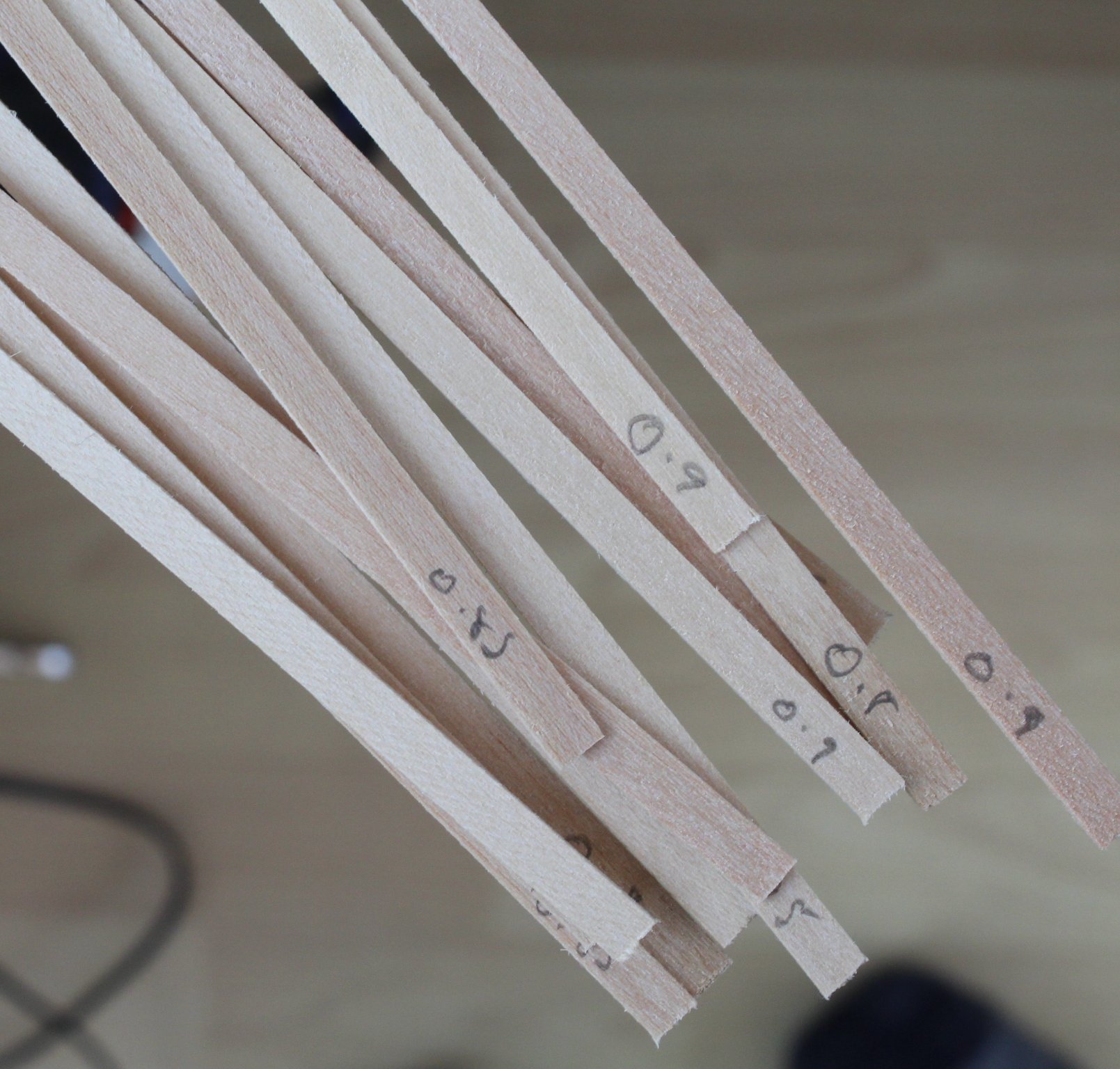
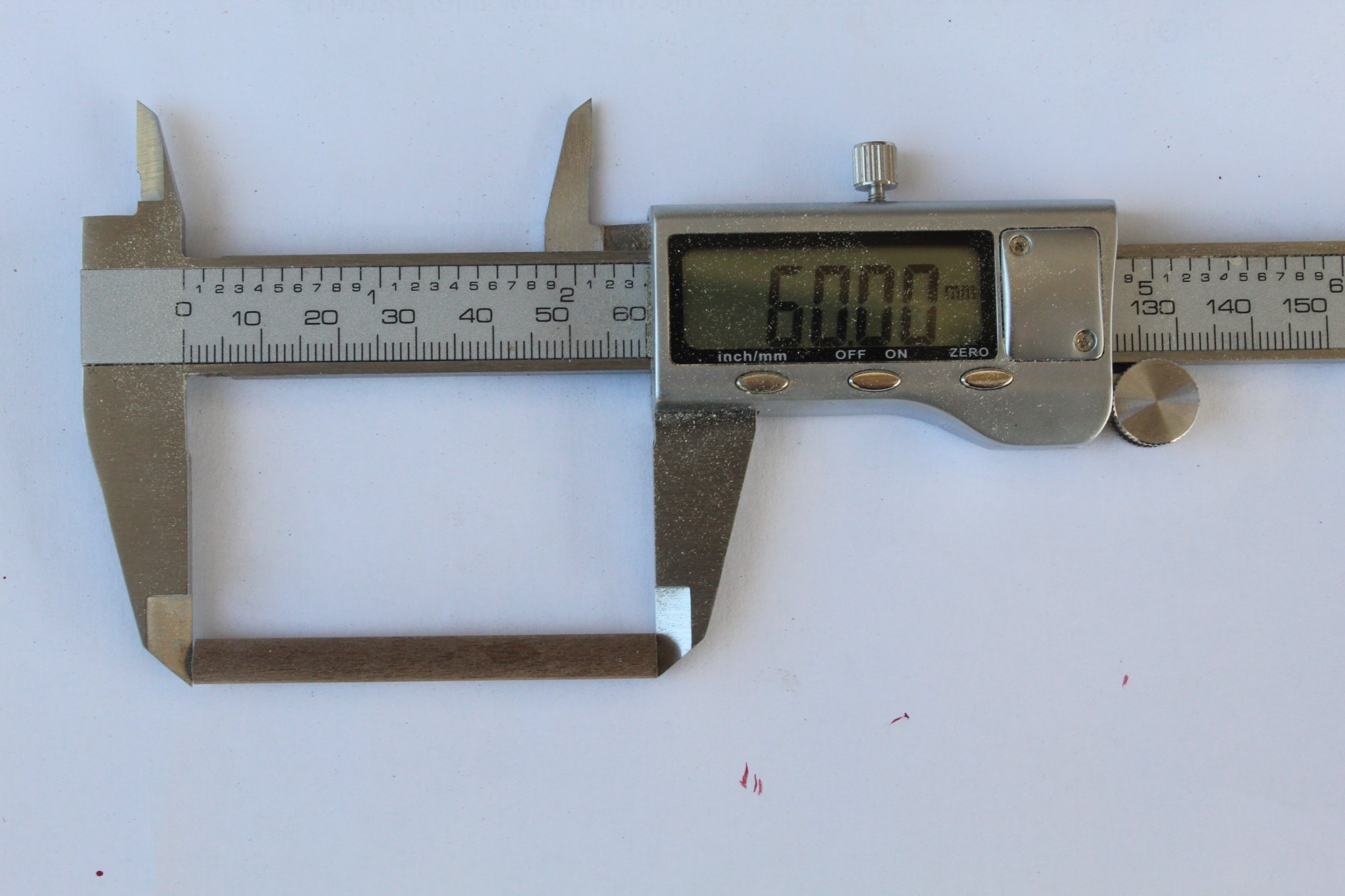
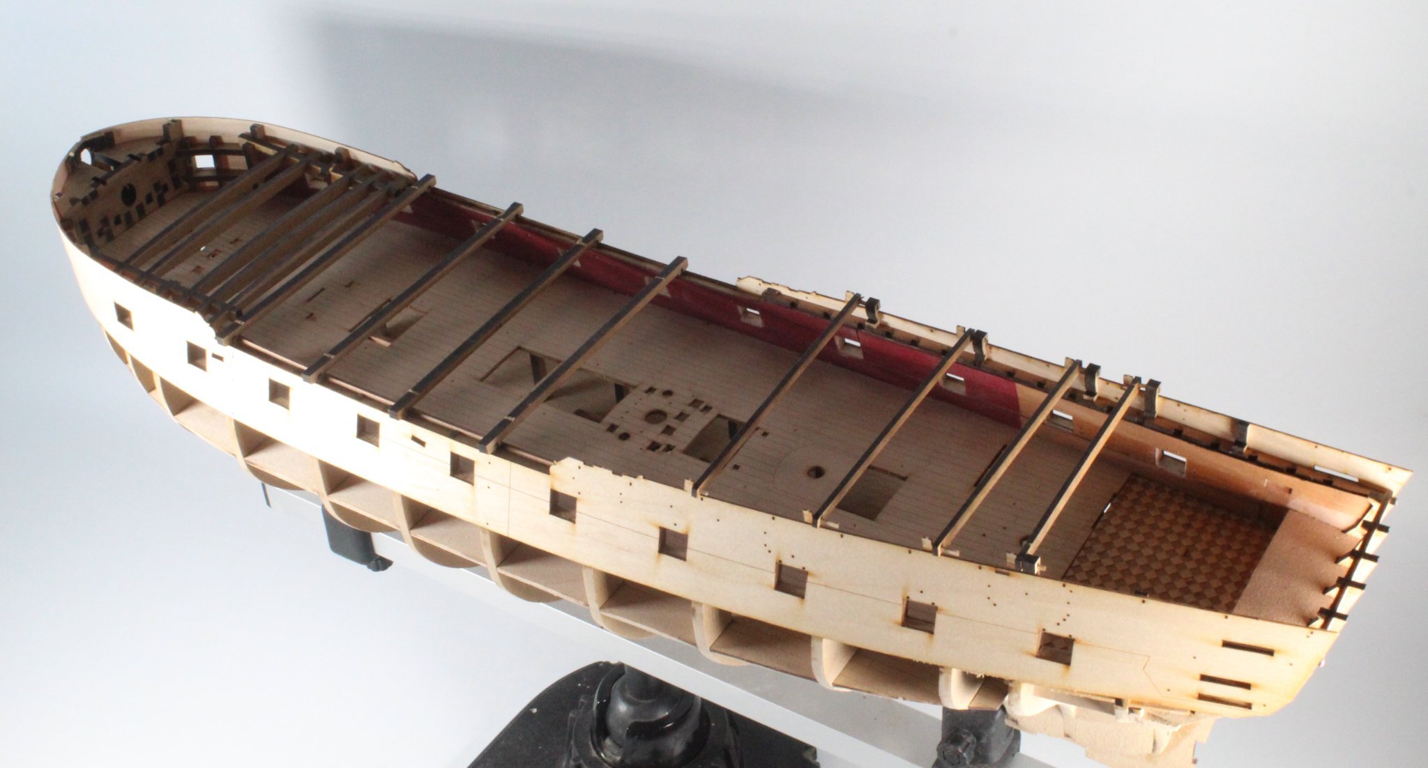
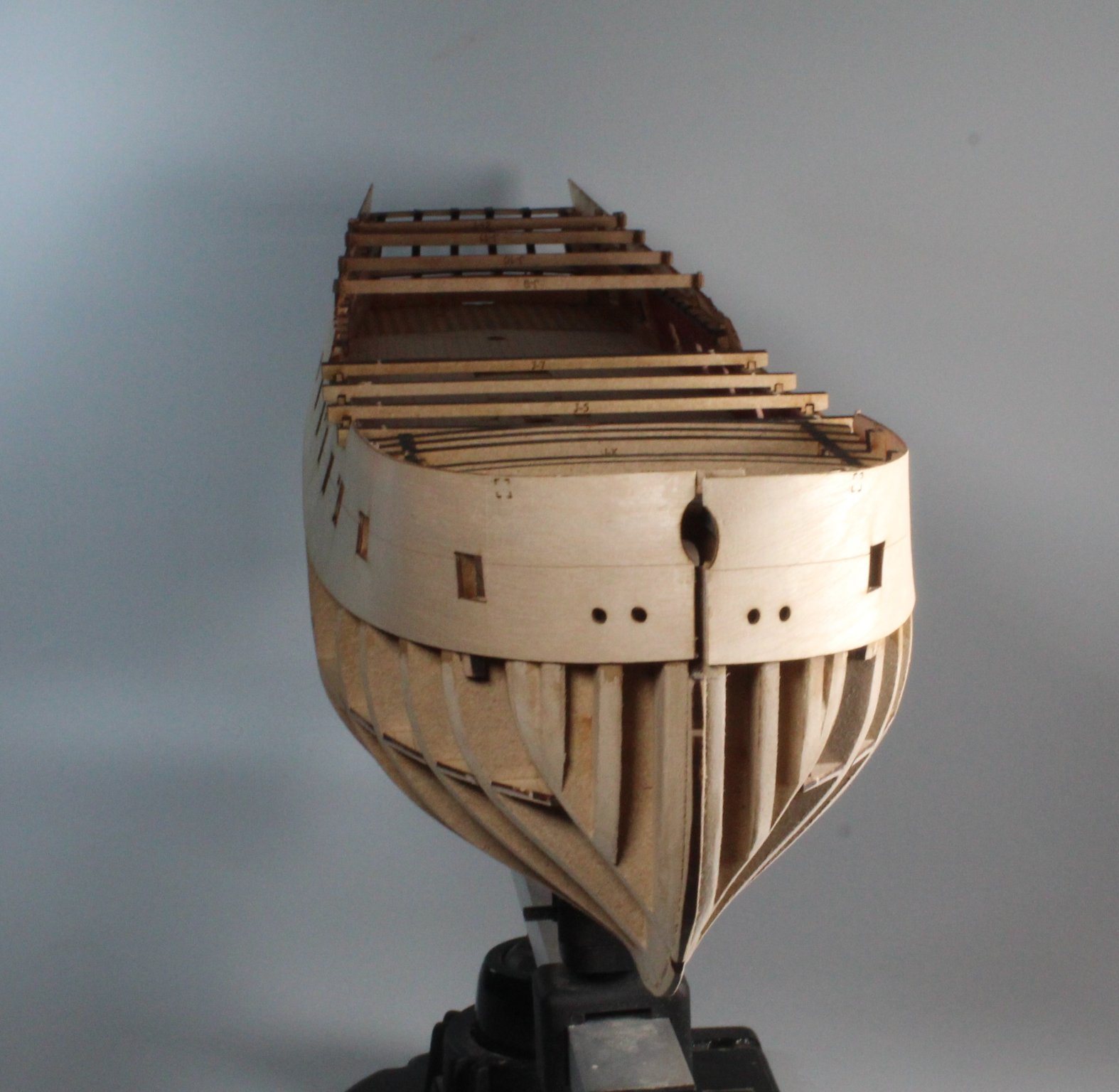
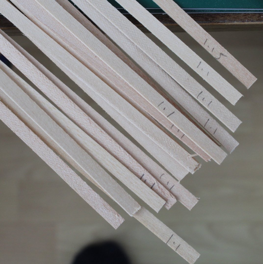
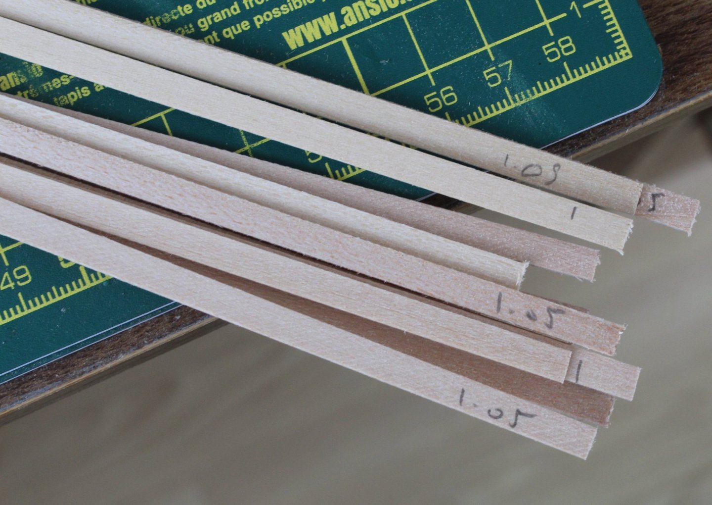
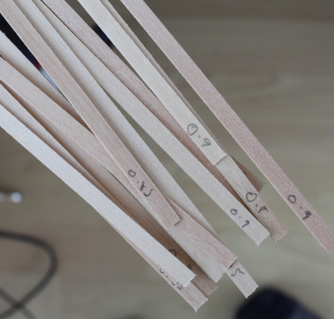
BUILD THOUGHTS FIRST PLANKING LINK TO MY BUILD LOG INDEX Planks In an attempt to get a more even planking I decided it would be a good idea to sort through the planking material and sort into groups based on the plank’s measured depth. I used my digital vernier gauge, checking at both ends of each plank and at several points along the plank. I then marked the depth on the planks, at each end. Picture of the sorted planks These are the rejects as they are too thin, and will only be used only if necessary. These planks are all under 1mm thick (0.8 to 0.9mm), so I plan to use these toward the keel This is the thickest group of planks (1.1 to 1.15mm) and will be the first group of planks used The final group is the 0.95 to 1.05mm grouping. Method I cut some cardboard strips and measured the length of each bulkhead and calculated that I would need 23 planks around the midships, reducing to 14 plank widths at the bow and 19 plank widths at the stern. In the manual James’s noted the first three planks were fitted without any tapering required. I did a dry fit test and concluded it is possible to fit the first three planks without the need to taper. I was a bit concerned with the natural flow of the first plank from the midship section to the stern due to the upward curvature of the hull pattern. I think with glue and pins it should be Ok. This picture shows the upward curve Clamping I also noticed there was quite a gap where the plank sits under the quarter gallery. This required a touch of glue and clamp as the bottom edge of the hull outer pattern was not in contact with the frame.


-
Looks nice.
-
I would be honoured to help out but I think my building skills are not good enough.
-
My build will be much slower. I'm predicting completion around July to September 2022
-
Thanks Malcolm
-
Time on my hands today while I was waiting for the realigned upper hull pattern to dry out so I thought I would make some simple assemblies.
-
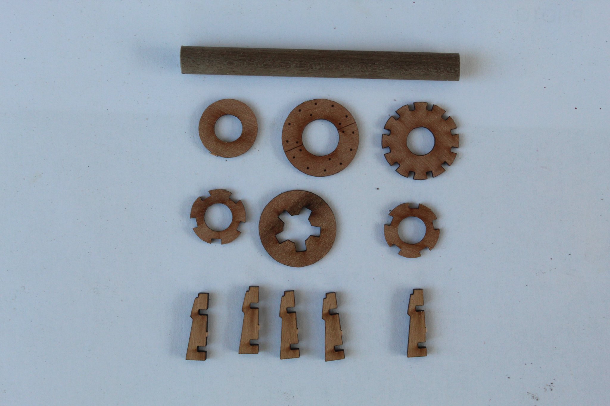
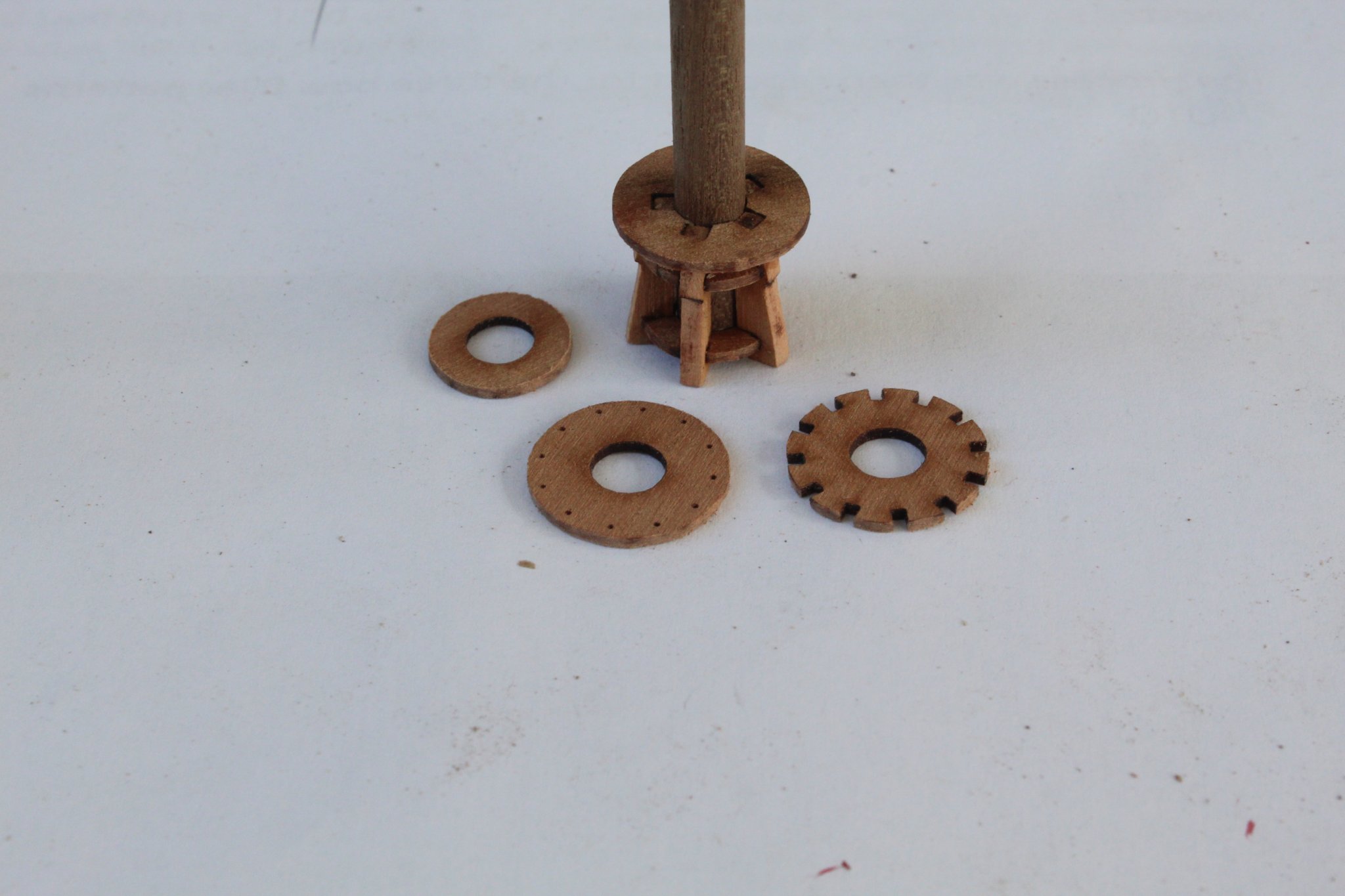
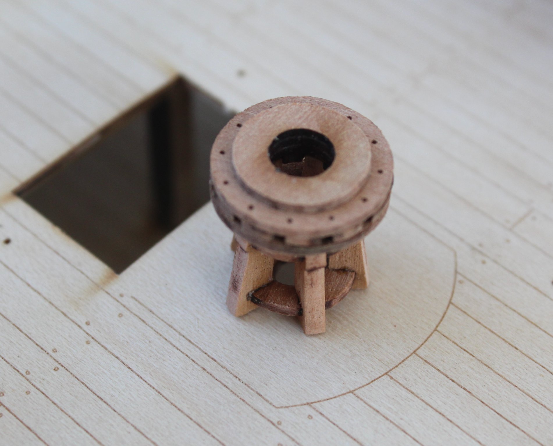
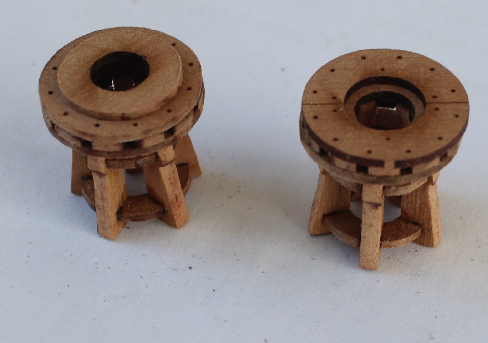
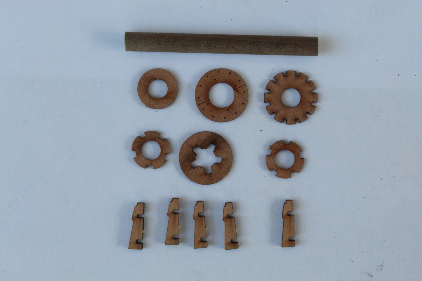
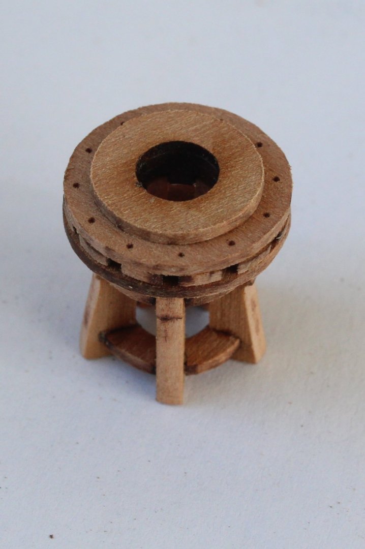
GUN DECK ASSEMBLY LOWER CAPSTAN ASSEMBLY BUILD MANUAL STEPS 463 - 469 UPPER CAPSTAN ASSEMBLY BUILD MANUAL STEPS 624 - 628 LINK TO MY BUILD LOG INDEX Tools Used Craft knife Flory sanding stick Titebond original glue Old paint brush Gathering the materials required The following kit parts are required for this section of the build: 250 (x2), 251, 252, 253, 254, 437 (x2), 60mm x 6mm dowel 60mm x 6mm dowel Capstan parts ready for assembly Assembly Process - Lower Capstan The 5 x capstan whelps were glued to the two capstan chocks. I then added the capstan lower drum head to the assembly and place the 6mm dowel through the central hole. The lower capstan is starting to take shape With the dowel in place the remaining items were glued to the capstan assembly and the dowel was then removed. The completed capstan assembly Picture of the capstan positioned on the gun deck Assembly Process – Upper Capstan The above process was repeated for the upper capstan assembly, The completed capstan's Both assemblies will be painting red later in the build process.


-
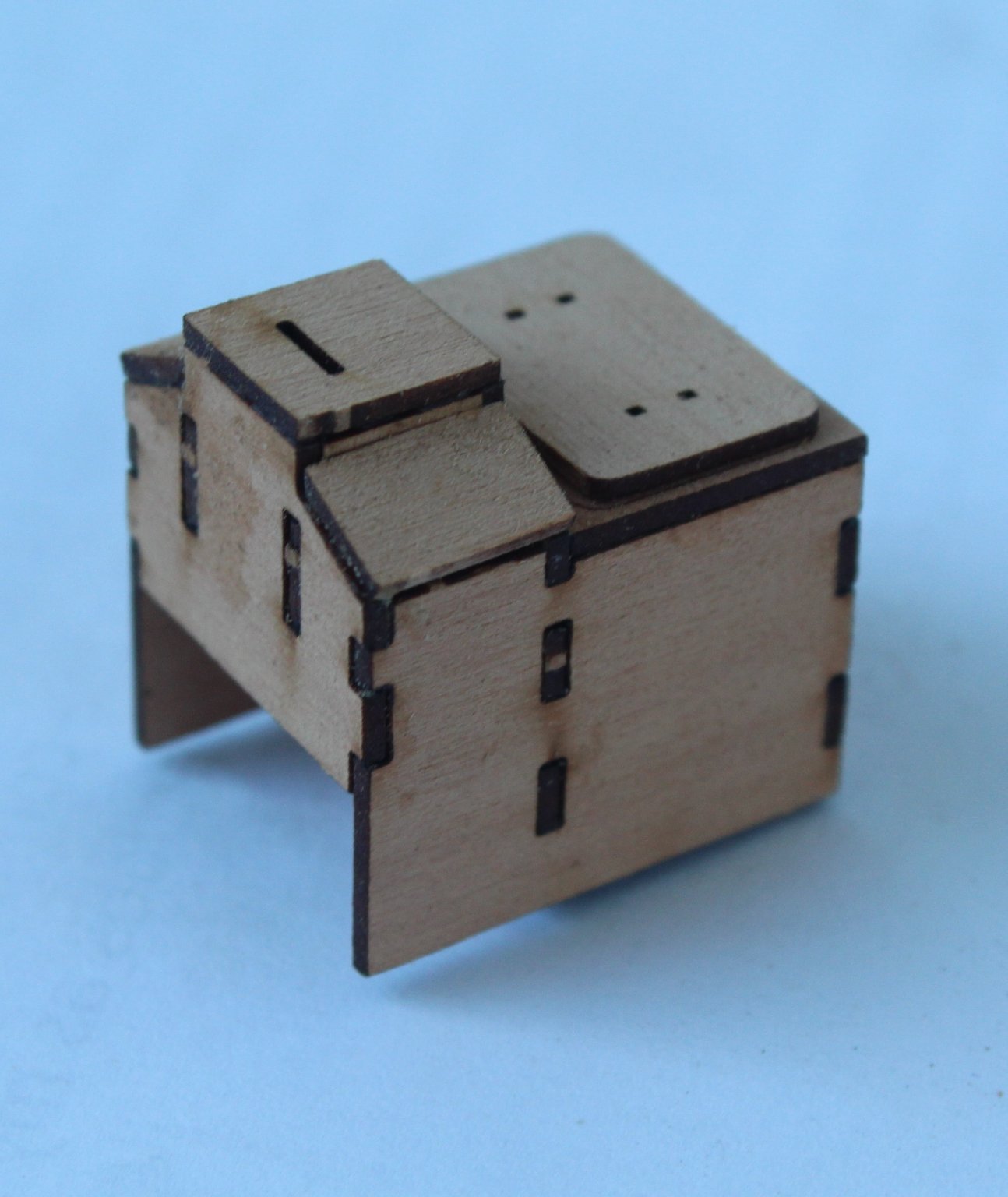
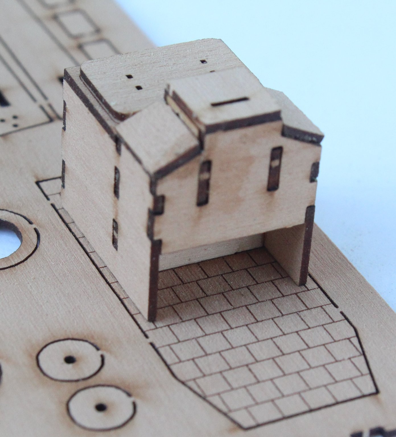
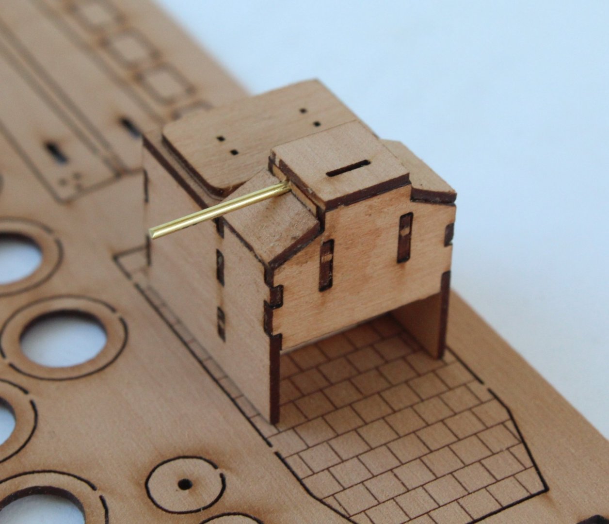
GUN DECK ASSEMBLY SHIP’S STOVE ASSEMBLY - PART 1 BUILD MANUAL STEPS 409 – 419 & 433 - 434 LINK TO MY BUILD LOG INDEX Tools Used Craft knife Flory sanding stick Titebond original glue Old paint brush Gathering the materials required The following kit parts are required for this section of the build: 204, 205 (x2), 206, 207, 208 (x2), 210, 211, 212 (x2), 1mm brass rod Assembly Process The various parts were dry fitted to ensure everything fitted. With no problems detected I followed the build instructions 410 to 419. It is important to note that the one edge of part 212 (x2) required a bevel before they are glued in place. I will add the PE parts later on in the build process, but I did a test fit of the assembly to ship stoves floor pattern. When looking at the remaining build stages I noted it was necessary to use a 1mm drill to open the half-hidden holes so a length of 1mm brass rod can be added.


-
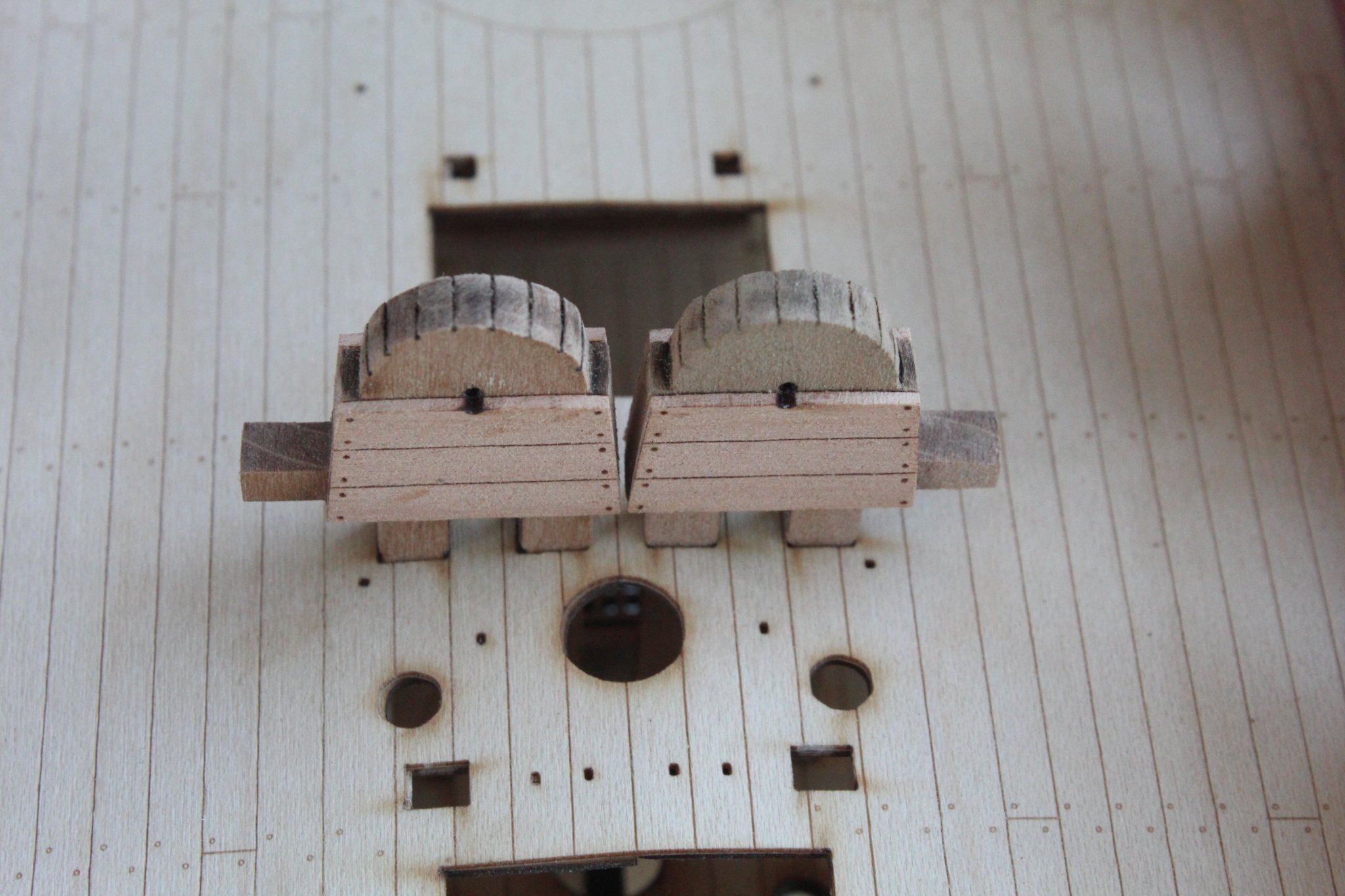
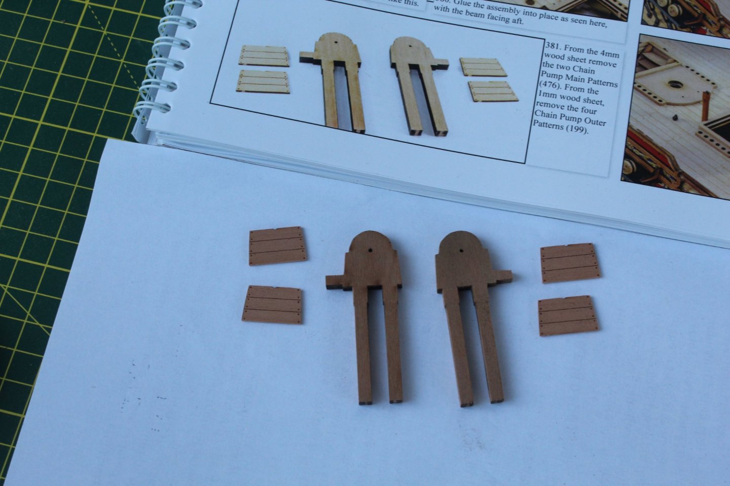
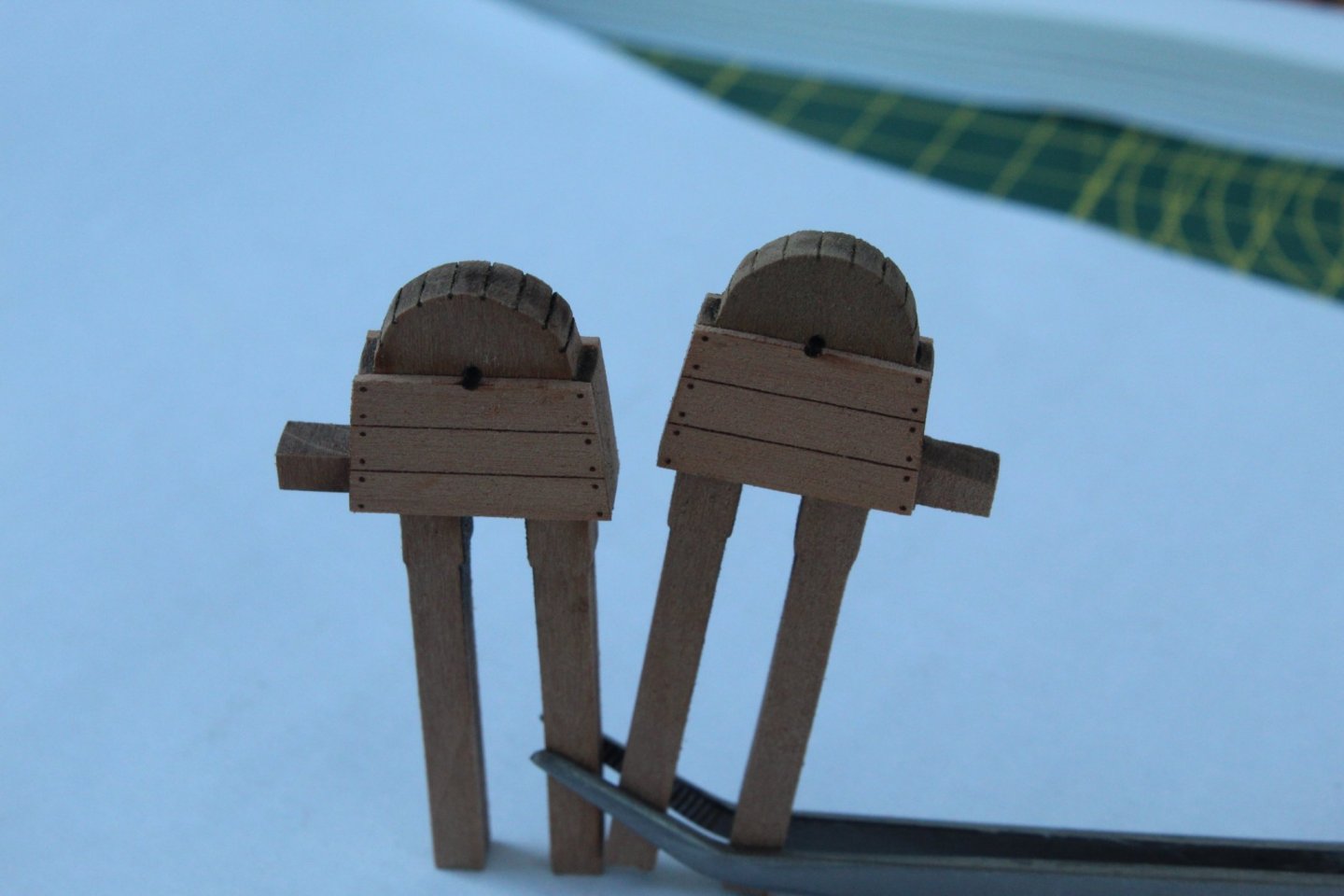
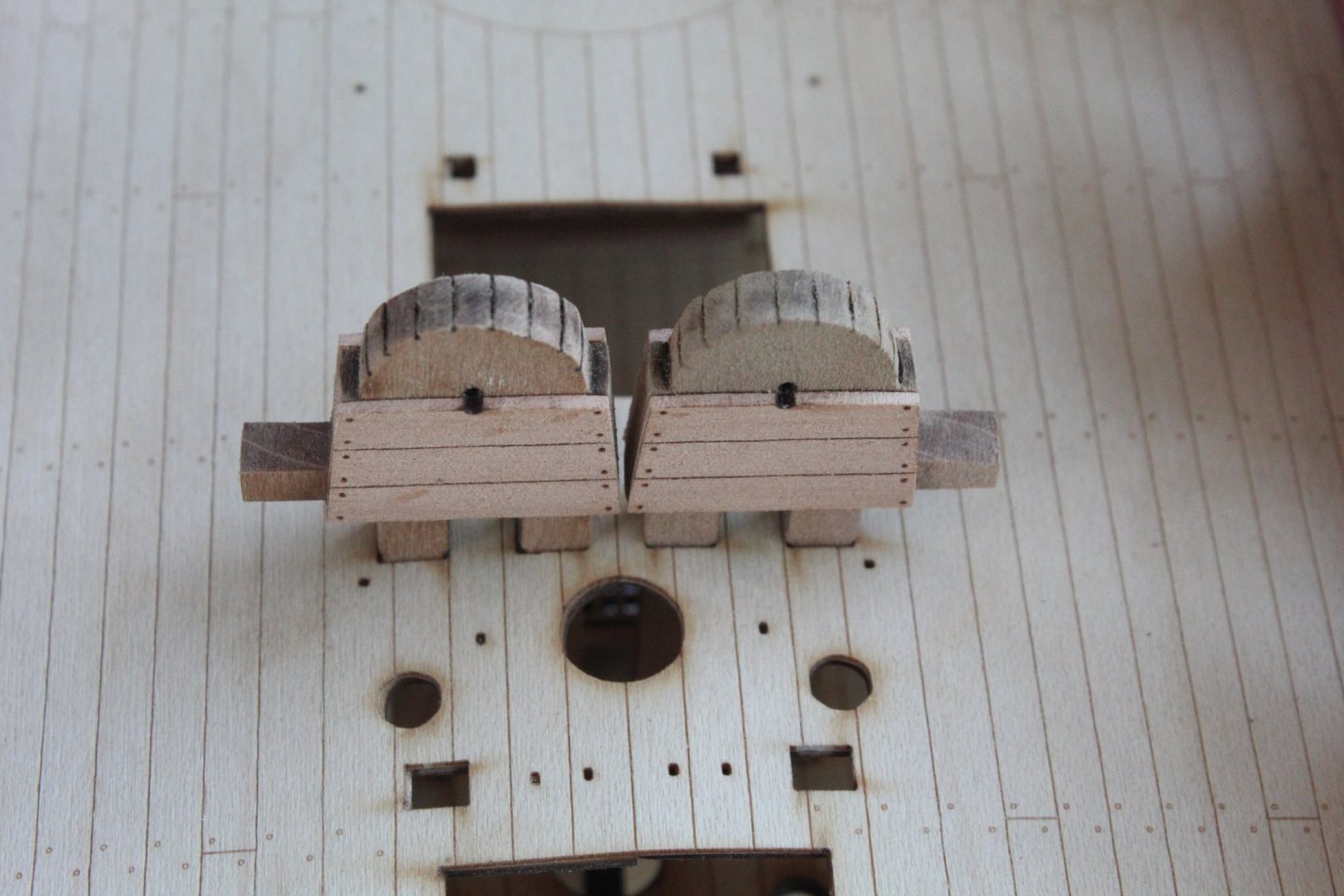
GUN DECK ASSEMBLY CHAIN PUMP ASSEMBLY BUILD MANUAL STEPS 381 - 383 LINK TO MY BUILD LOG INDEX Tools Used Craft knife Flory sanding stick Titebond original glue Old paint brush Gathering the materials required The following kit parts are required for this section of the build: 199 (x4), 476 (x2) Replicating James's build manual photo Assembly Process Not the most difficult task. I removed the laser char from the visible edges. Next I applied a thin coat of glue to the back of each chain pump outer patterns and then added them to the chain pump main patterns. The completed Chain Pumps The competed assemblies were then dry fitted to the gun deck to ensure they would locate in the slots. They were then removed as they will be glued in place later in the build process. I also need to apply a varnish.
-
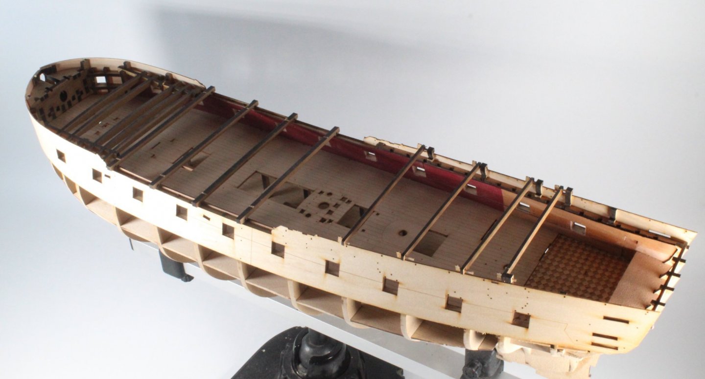
I am pleased to report I have managed to release the misaligned left-hand upper hull side pattern with application of water and a very sharp blade. I have clamped the pattern in place but I will need to allow time for the structure to fully dry out before I apply a fresh coat of glue. So I will move on to building more gun deck fixtures and fittings in the meantime.
-
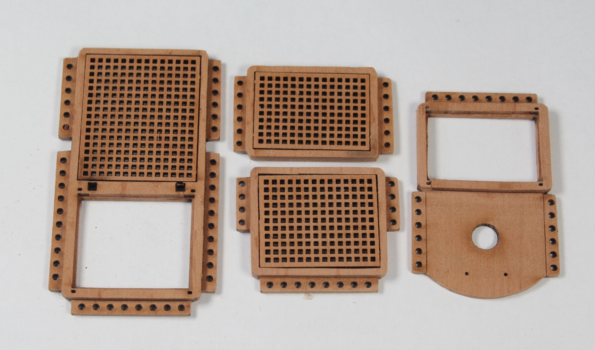
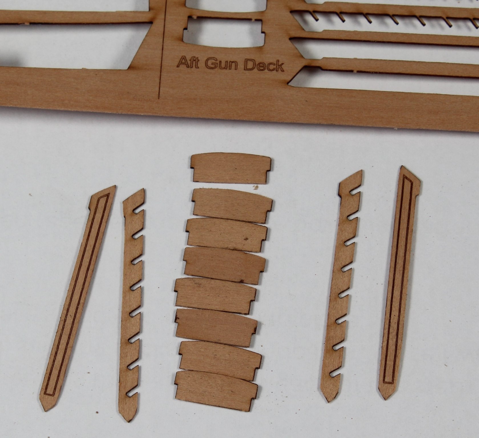
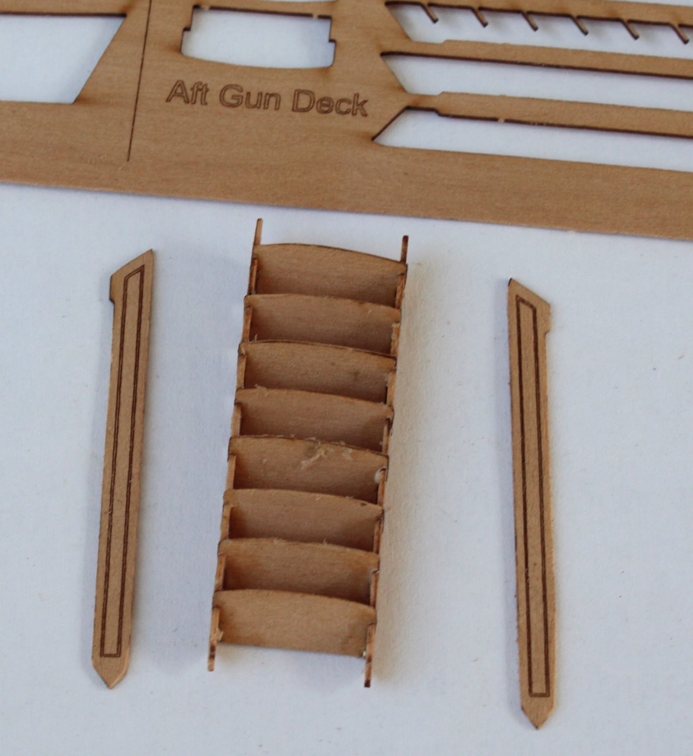
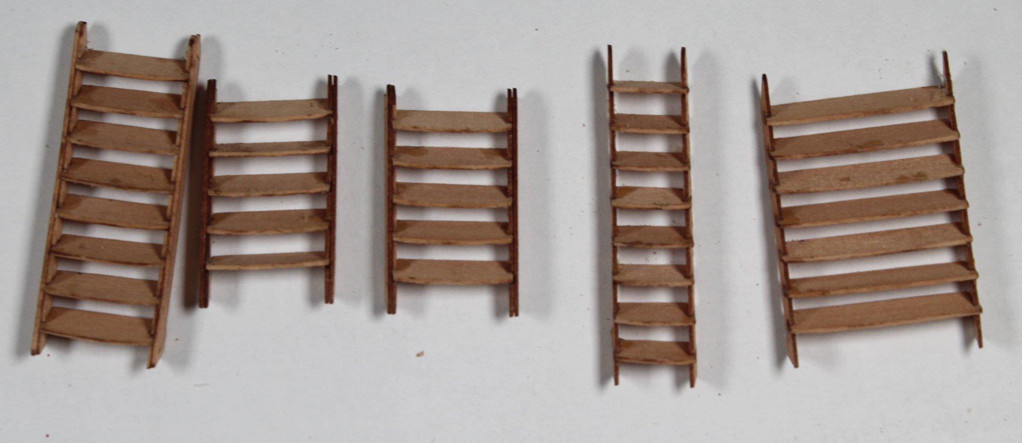
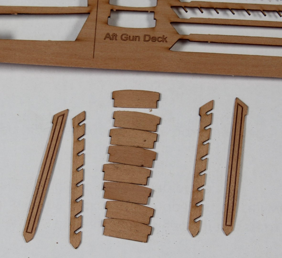
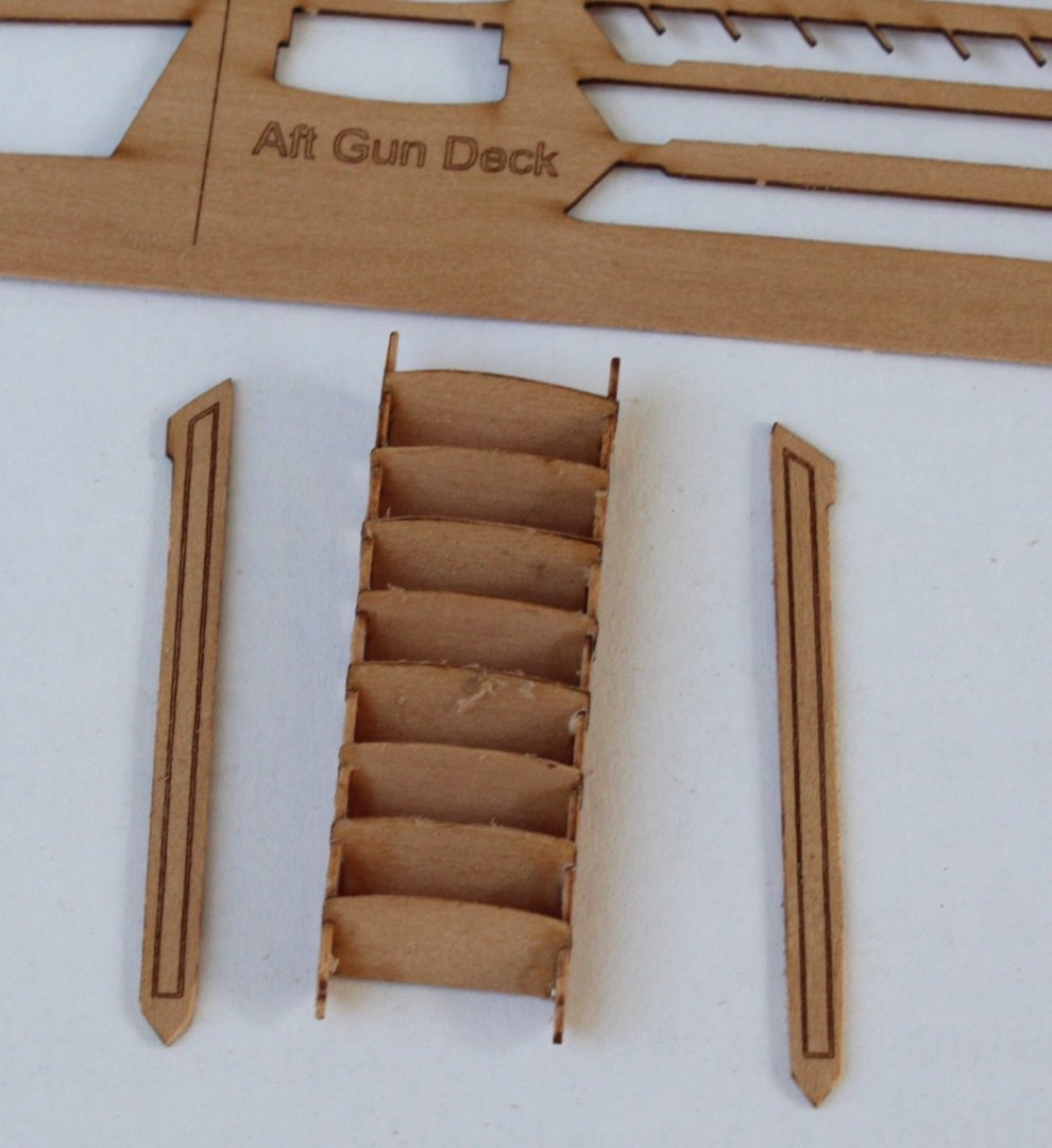
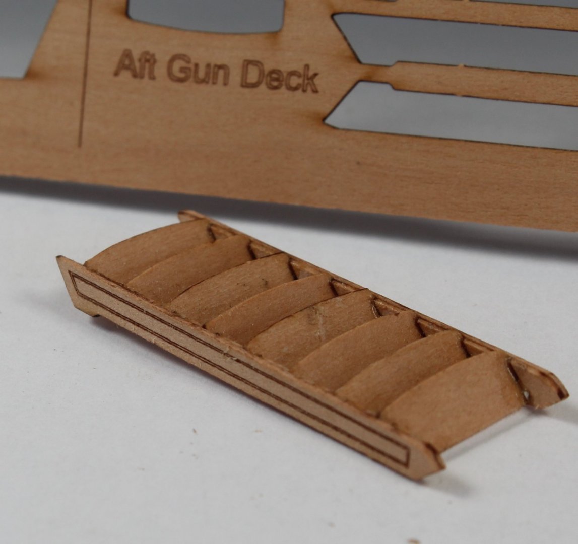
GUN DECK ASSEMBLY ASSEMBLY COAMINGS AND LADDERS BUILD MANUAL STEPS 350 - 370 LINK TO MY BUILD LOG INDEX Tools Used Craft knife Flory sanding sticks Titebond original glue Old paint brush Clamps Gathering the materials required The following kit parts are required for this section of the build: 116-131 & 353-365 Assembly Process - Coamings Using a sanding stick I removed the laser char from all the visible edges, taking great care as some aspects are very fragile. Glue was then applied to the upper parts and then they placed on their respective lower parts. Clamps were used to ensure the parts were held firm as the glue cured. The grating covers were dry fitted and the completed coamings were put to one side as they will be added to the gun deck later in the build process. Completed coamings Assembly Process - Ladders Each ladder comprised several items, as follows: Side inner rails Side outer patterns Steps Aft Gun parts Aft Gun Deck Ladder Assembly I started the assembly process by gluing 3 steps to one of the inner side rails, one step in the top slot, one step in the middle slot and one step in the bottom slot. The assembly was then left for approx. 10 minute to allow time for the glue to grab before the other inner side rail was added. It was then a simple process to fit the remaining steps. I then brushed some diluted glue on the outside edge to ensure the steps were fully glued in place. Aft ladder ready for outer side patterns to be added Once the glue had cured the outside edge of the ladders were sanded smooth before the outer side patterns were glued in place. Completed Aft Gun Deck Ladder The assembly process was then repeated for the other 4 ladders. The completed ladder assemblies were put to one side and will be added to the gun deck later in the build process. All completed ladders


-
@BobG I had already edited my post. I will release the bow section (using water) and realign.
-
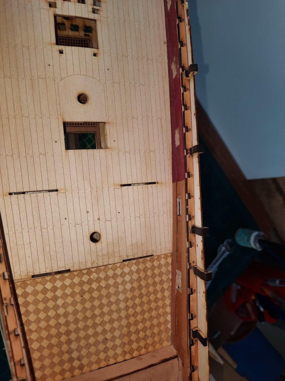
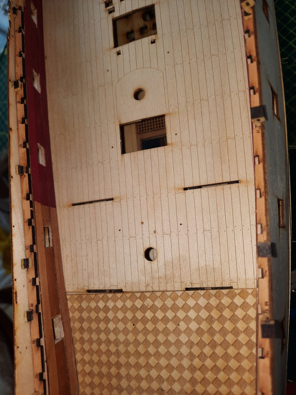
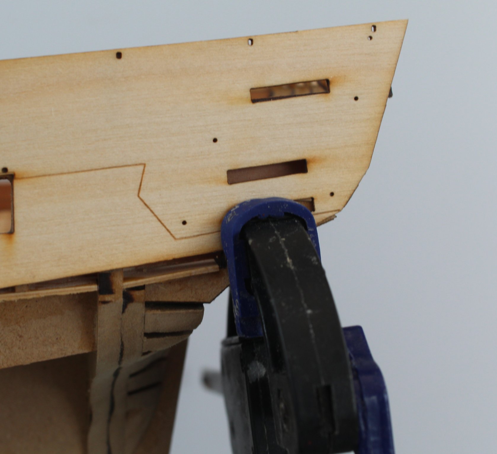
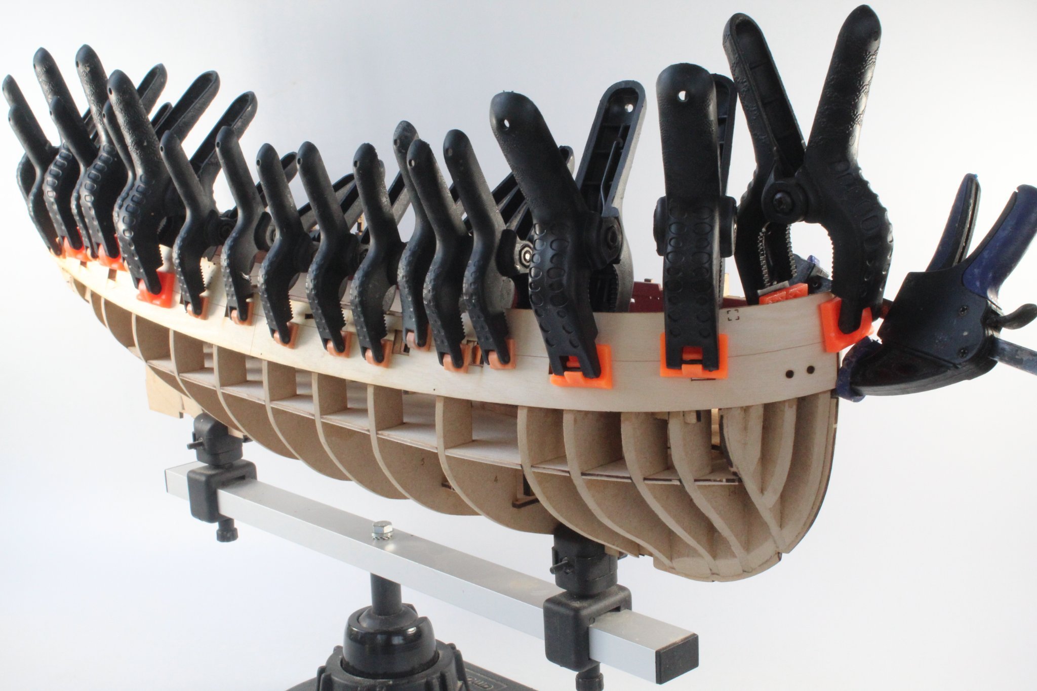
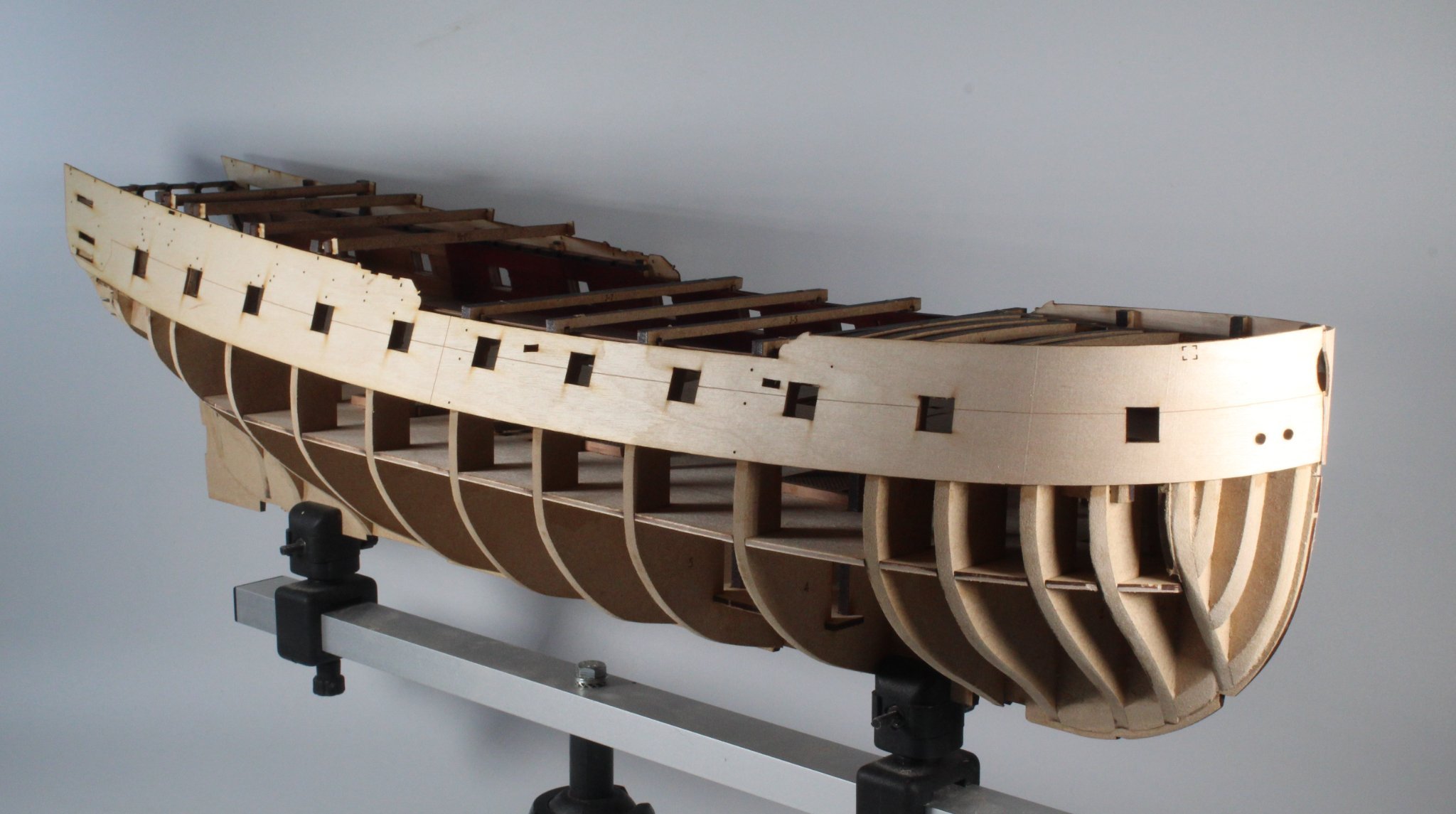
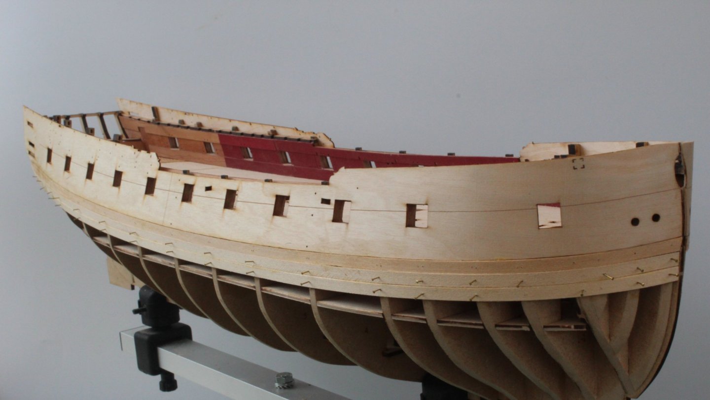
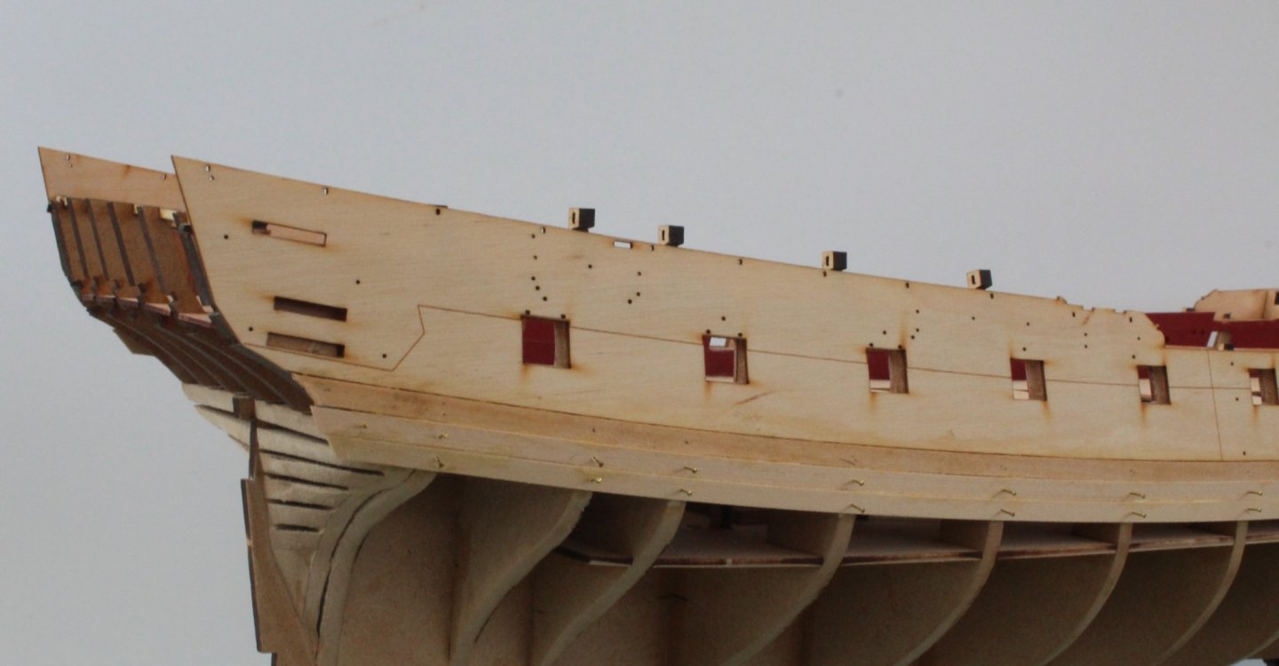
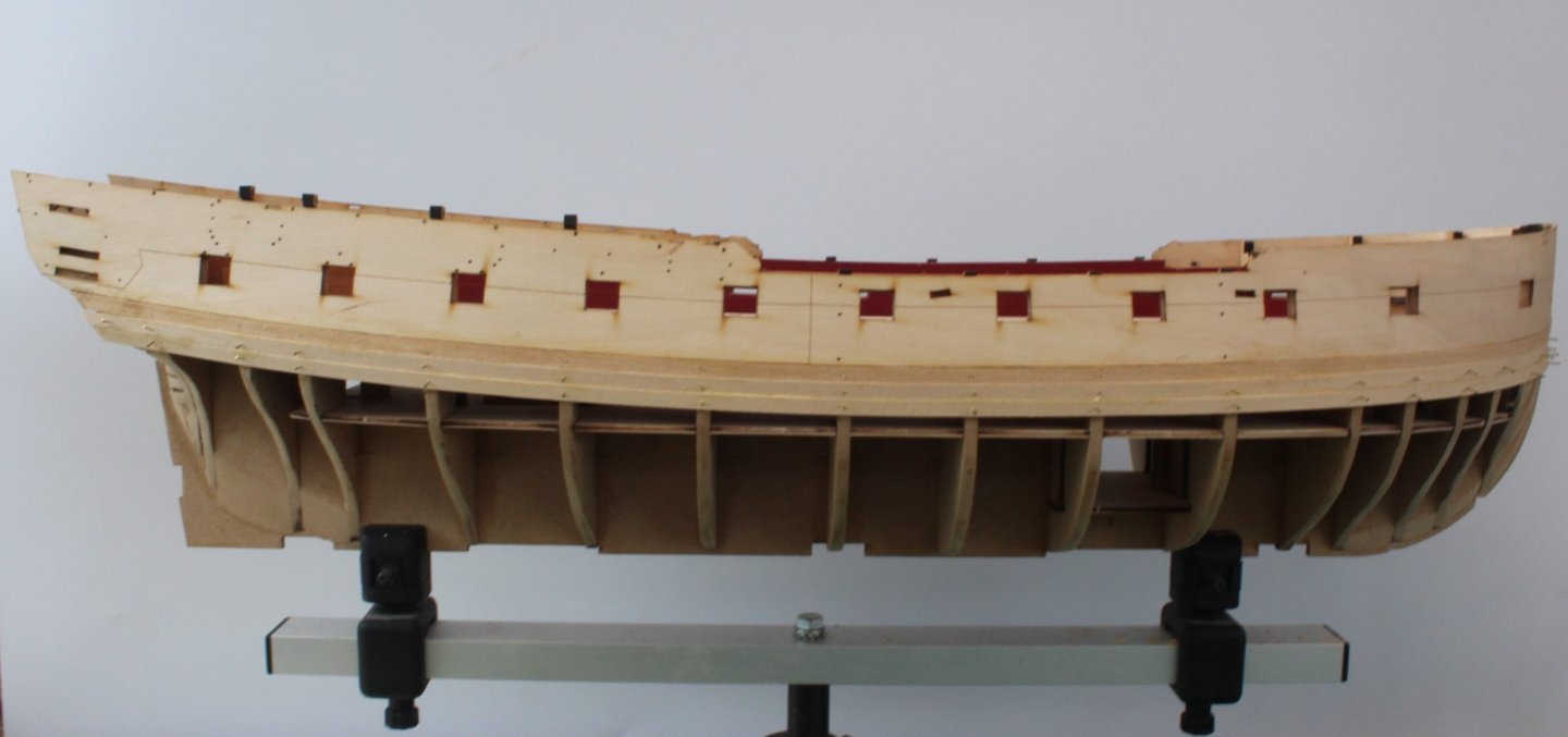
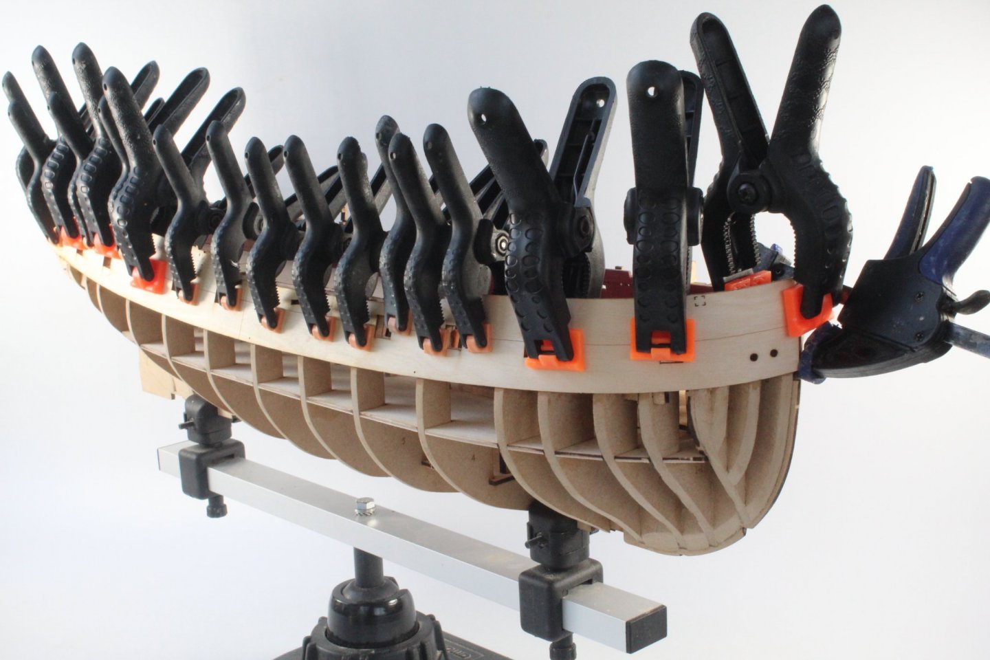
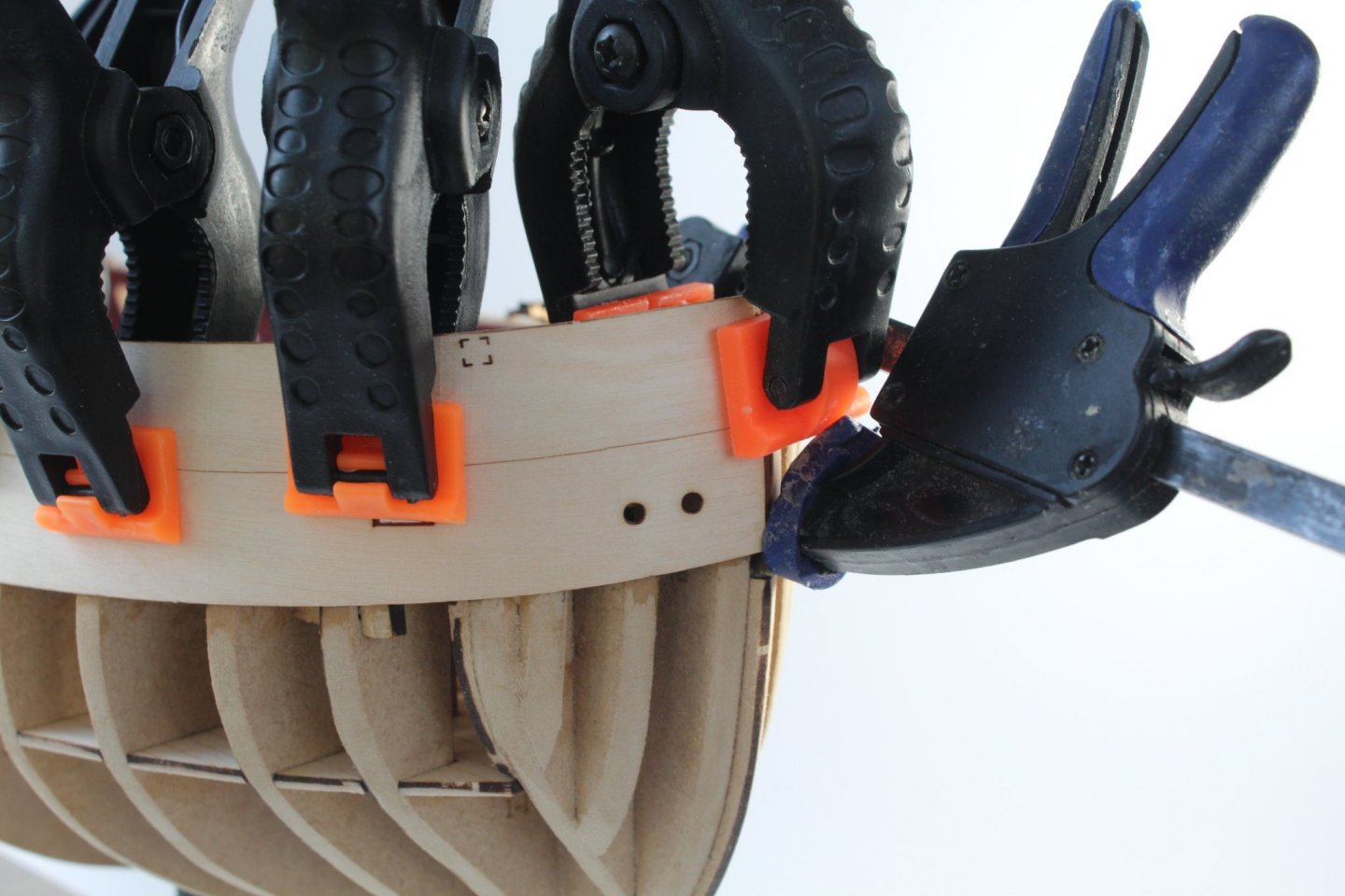
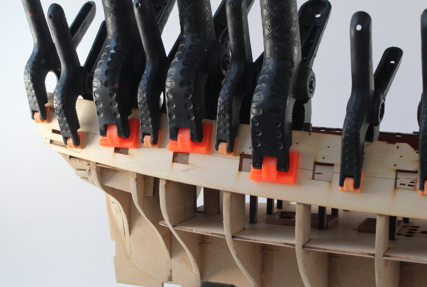
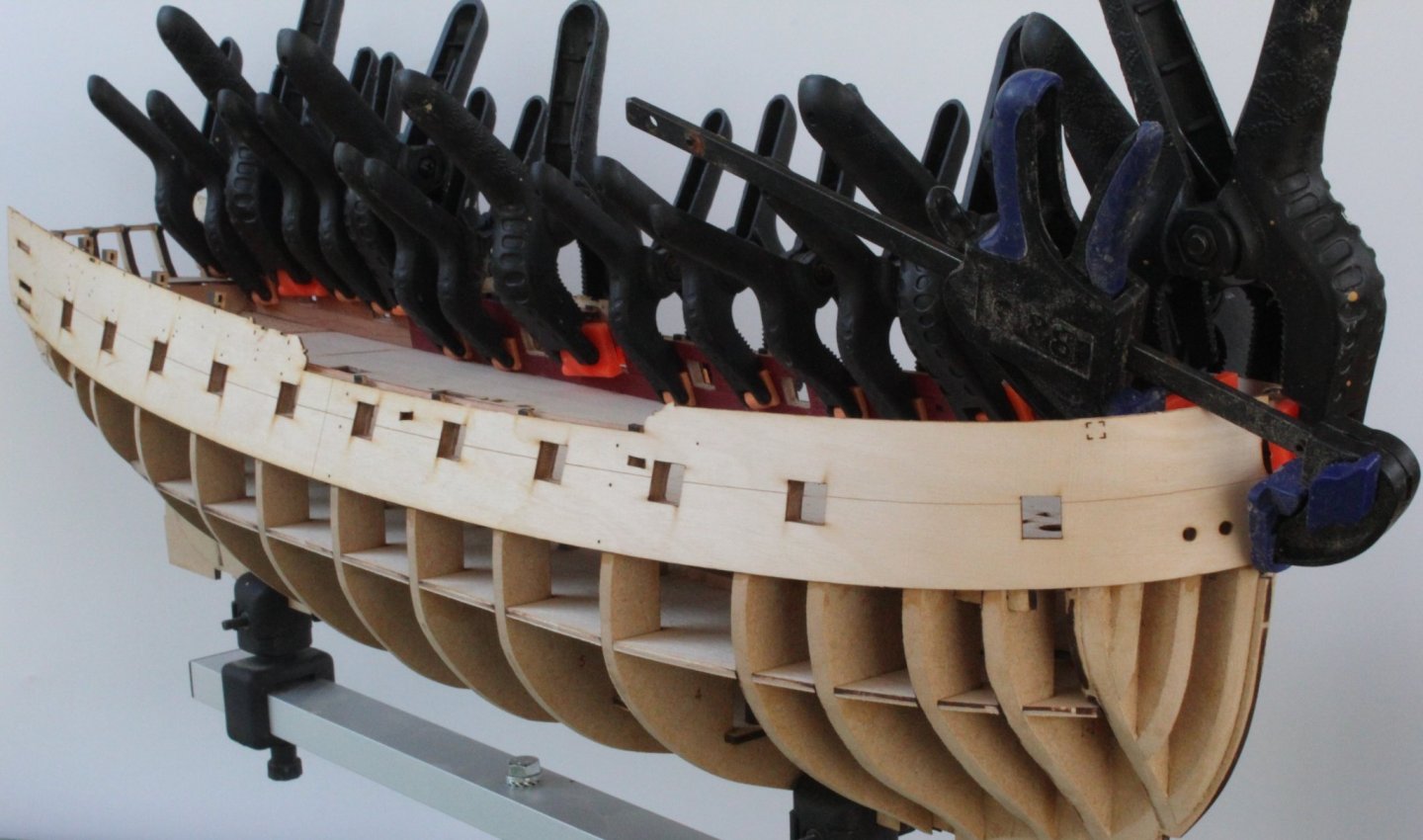
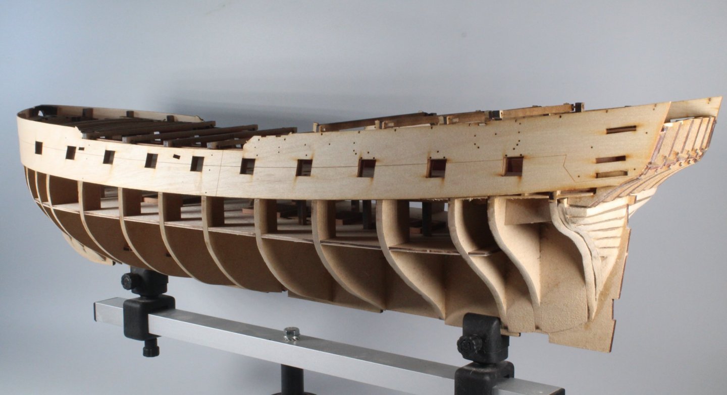
HULL ASSEMBLY ADDING THE UPPER HULL SIDE PATTERNS BUILD MANUAL STEPS 134 -137 LINK TO MY BUILD LOG INDEX Tools Used Titebond original glue Old paint brush Clamps Gathering the materials required The following kit parts are required for this section of the build: 136, 138 Assembly Process The hull side patterns were removed from the hull, after being left clamped to the hull for approx. 18 hours to fully dry out. I was concerned with a little bit of bulging of the patterns near the stern area. On closer examination I found the problem was due to an alignment issue with a couple of the repaired bulkhead ears, which had broken off during the fairing process. I decided to remove two of the damaged ears and this solved the bulging problem. Starting with the right-hand pattern I applied a diluted glue solution to the hull frame. I then carefully aligned the pattern with the first couple of gun port openings and added a clamp. More clamps were added as I continued to align the pattern moving toward to the stern. Finally, I applied clamps to the bow area and the hull was put aside to allow time for the glue to cure. . I used all my clamps Close up of the bow clamping Clamping the stern area I repeated the process for the left-hand pattern. Death by clamping😂 After the glue had had time to cure the clamps were removed and I stood back to admire my work as instructed in step 130 of the build manual 😀 There is a slight misalignment at the bow. I will use some water to release the front edge and realign as necessary.


-
You're moving on nicely
-
Looks good. Mine needed very little touch up when fairing the hull
-
Looks good to me and I am sure you will do a great job.
-
I like using Florey standing sticks. I have never used or seen a sanding sponge
-
I used a very similar method sanding the crap out of the hull using my Amati sanding block (40mm wide) fitted with 100-grit sandpaper for the majority of the fairing. I think this is a great tool. When there was a bit more extra material to remove I used my mini power sander and / or a course grained Florey sanding stick before reverting the Amati sanding block to complete the task.