Glenn-UK
-
Posts
3,169 -
Joined
-
Last visited
Content Type
Profiles
Forums
Gallery
Events
Everything posted by Glenn-UK
-
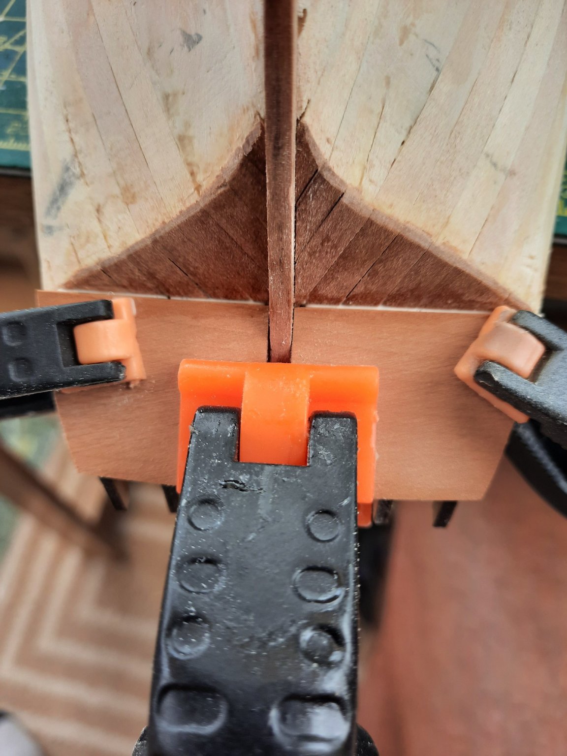
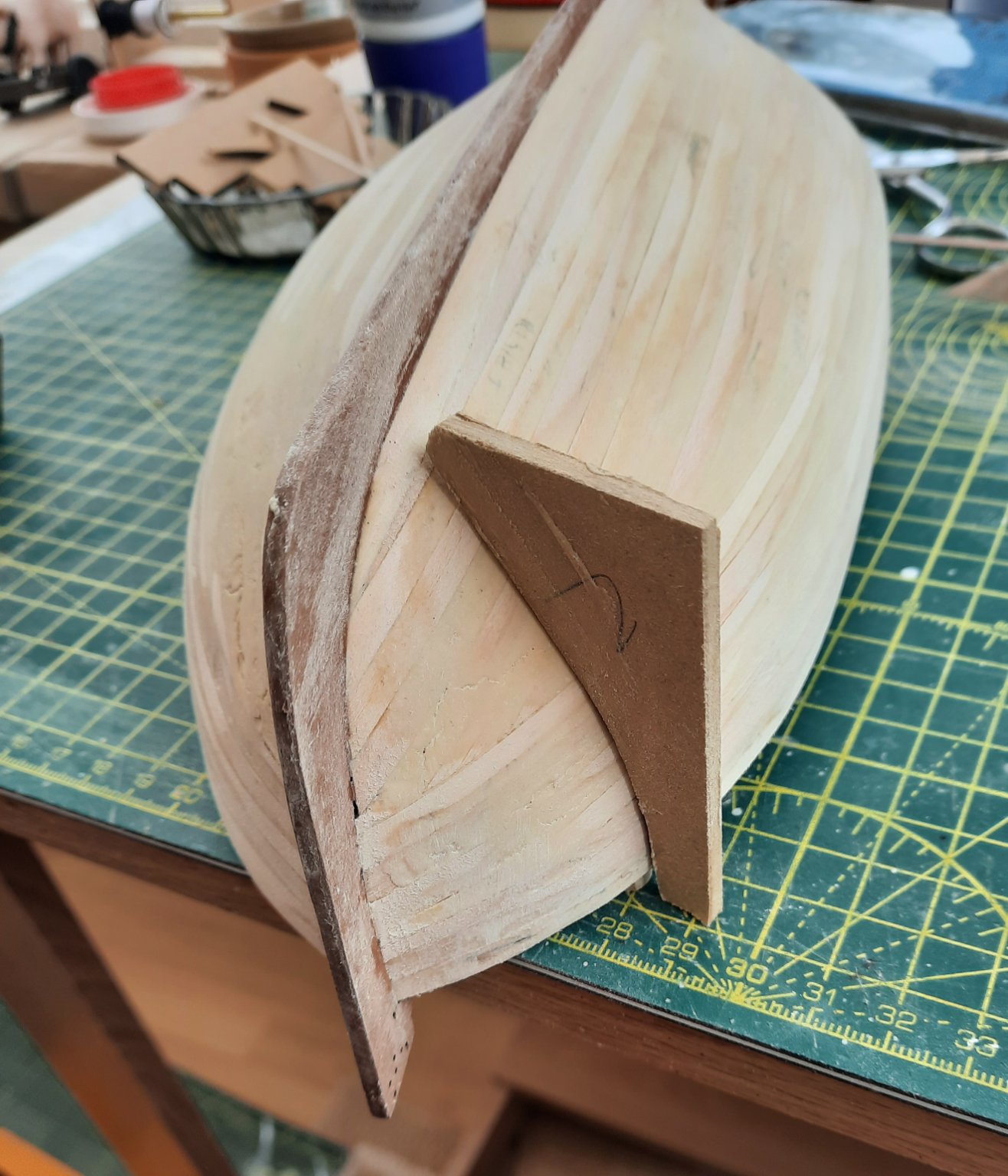
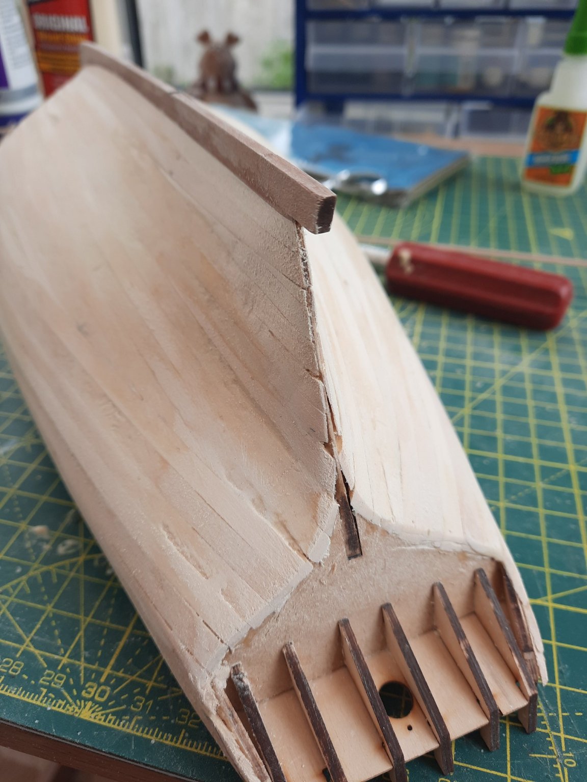
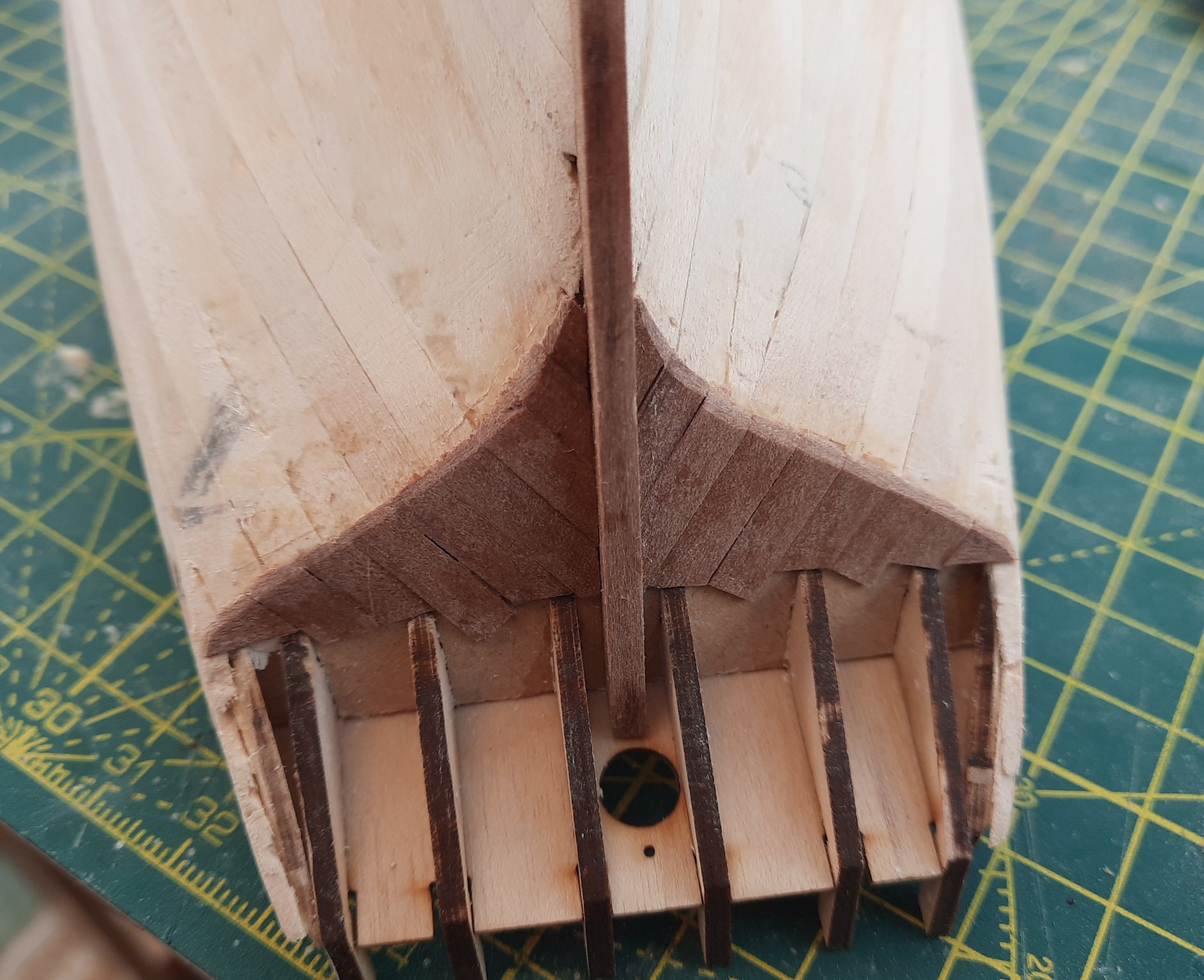
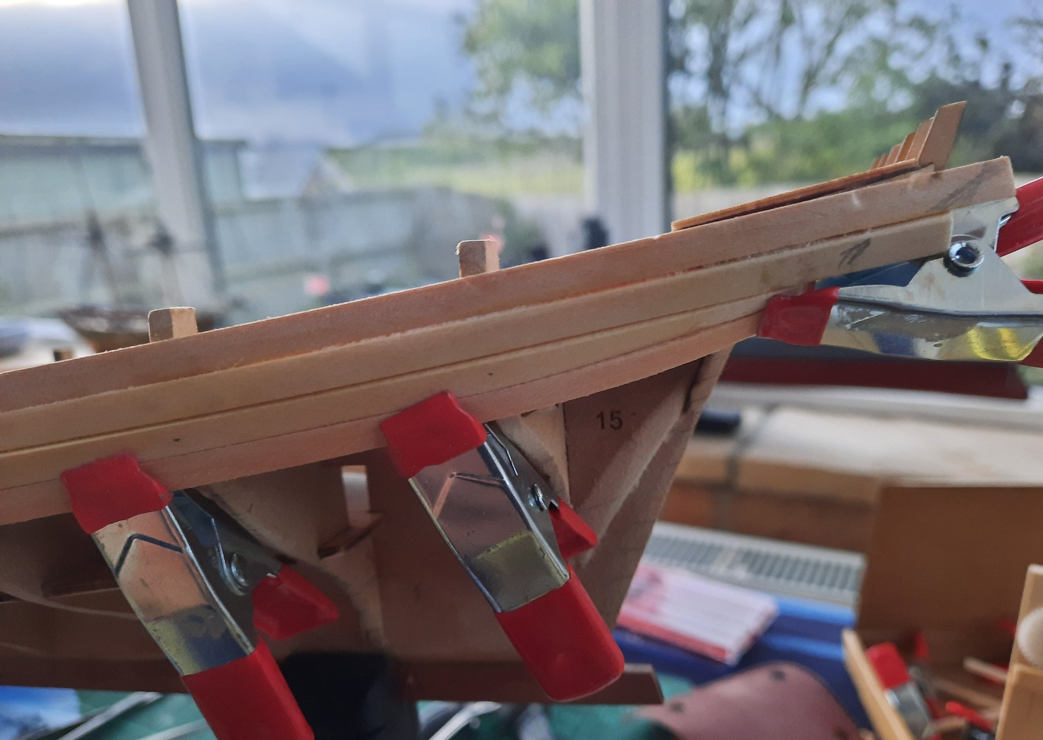
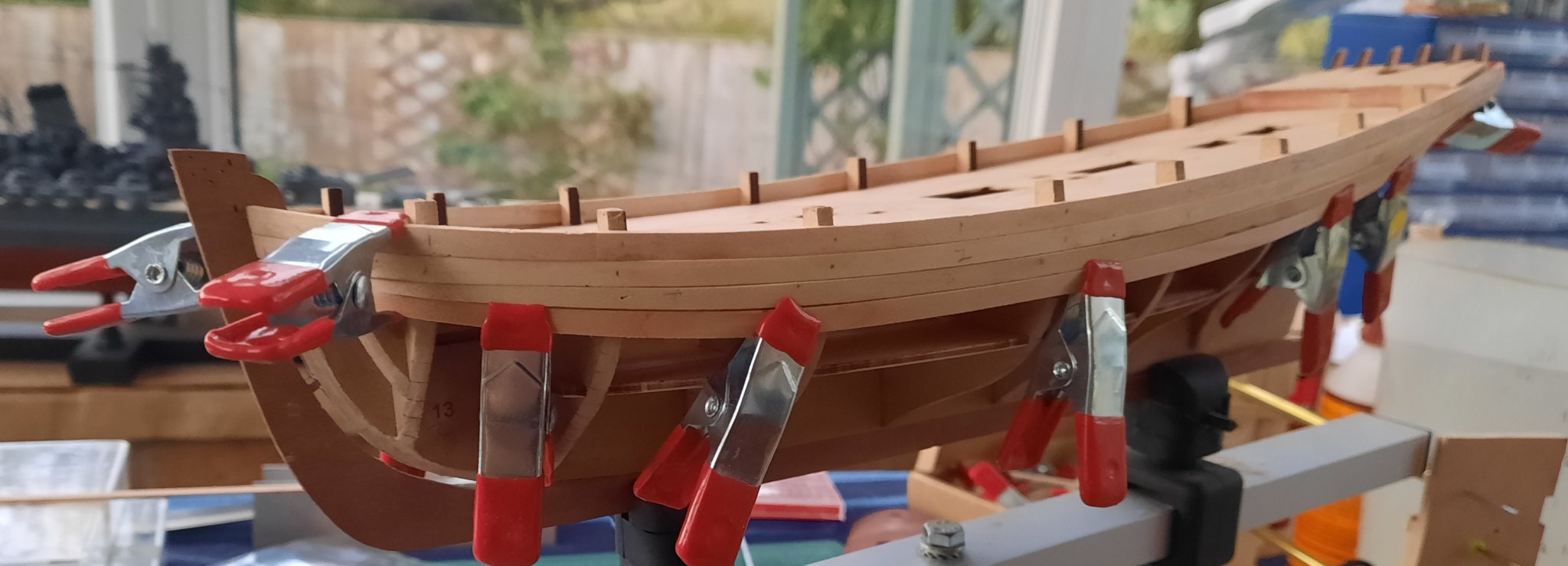
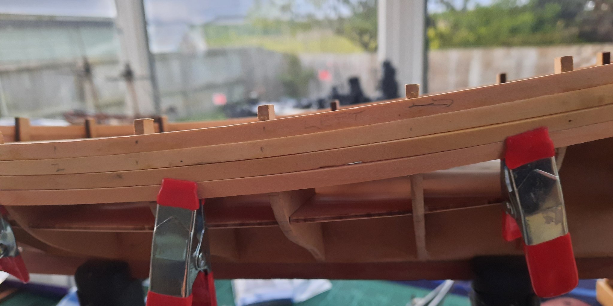
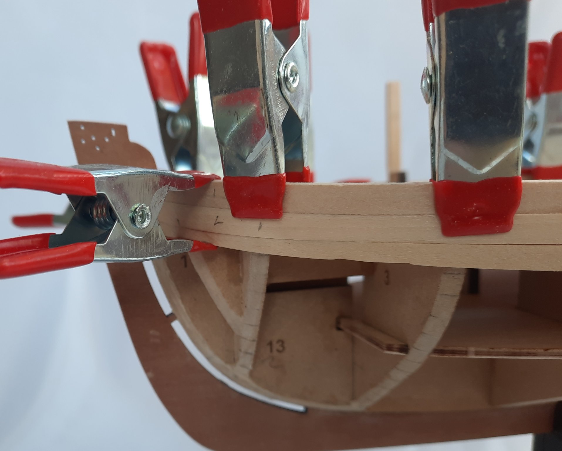
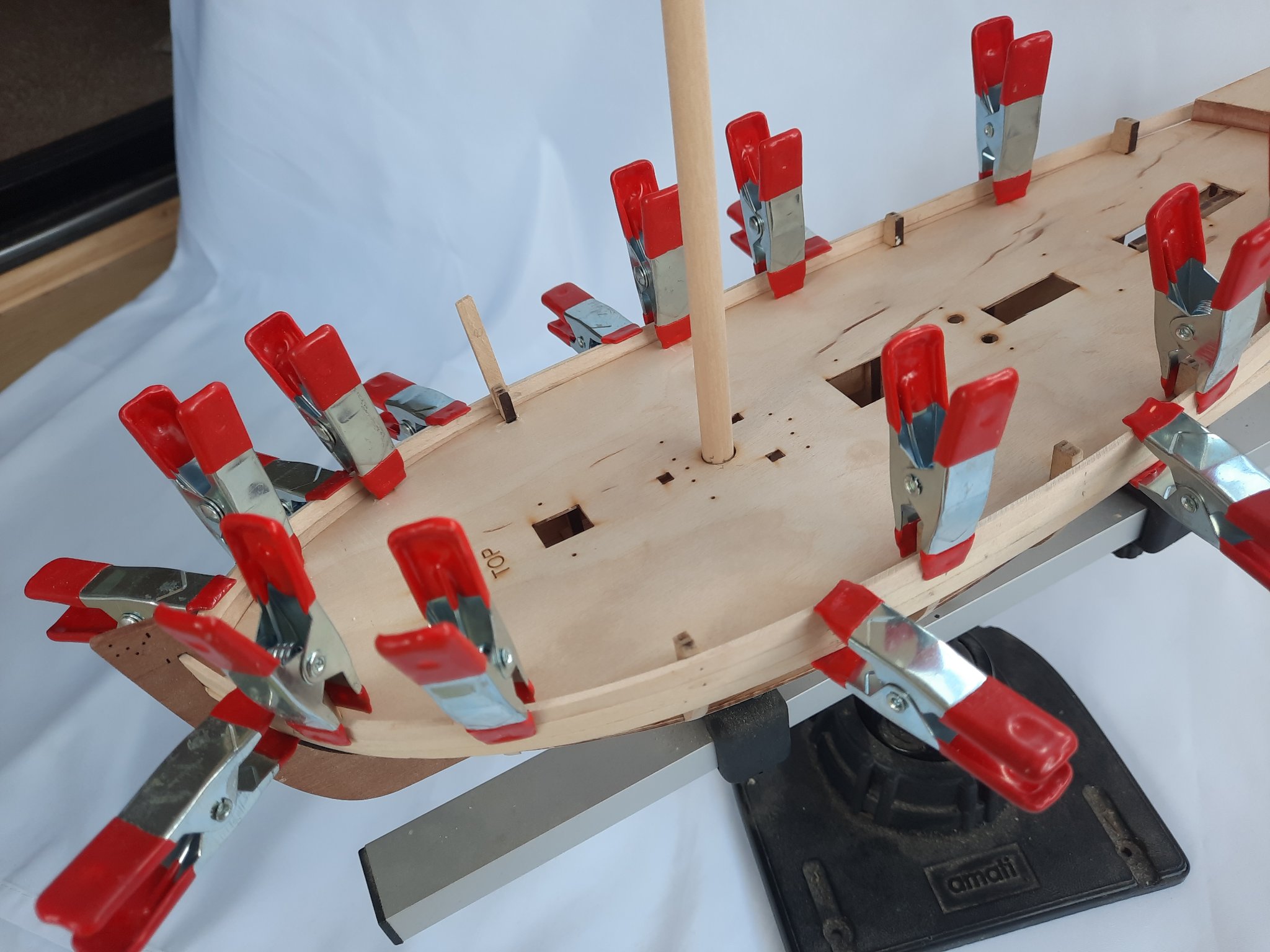
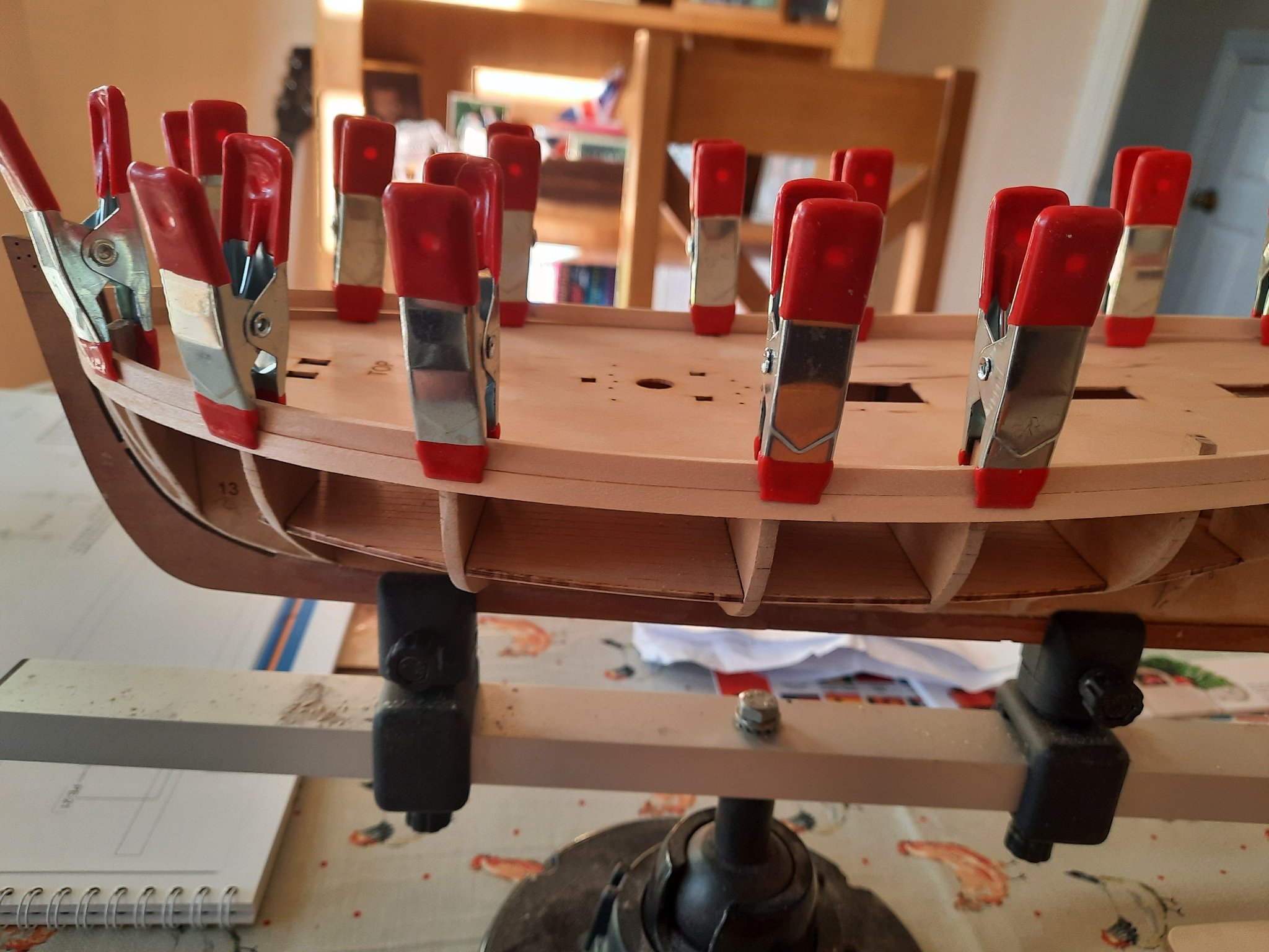
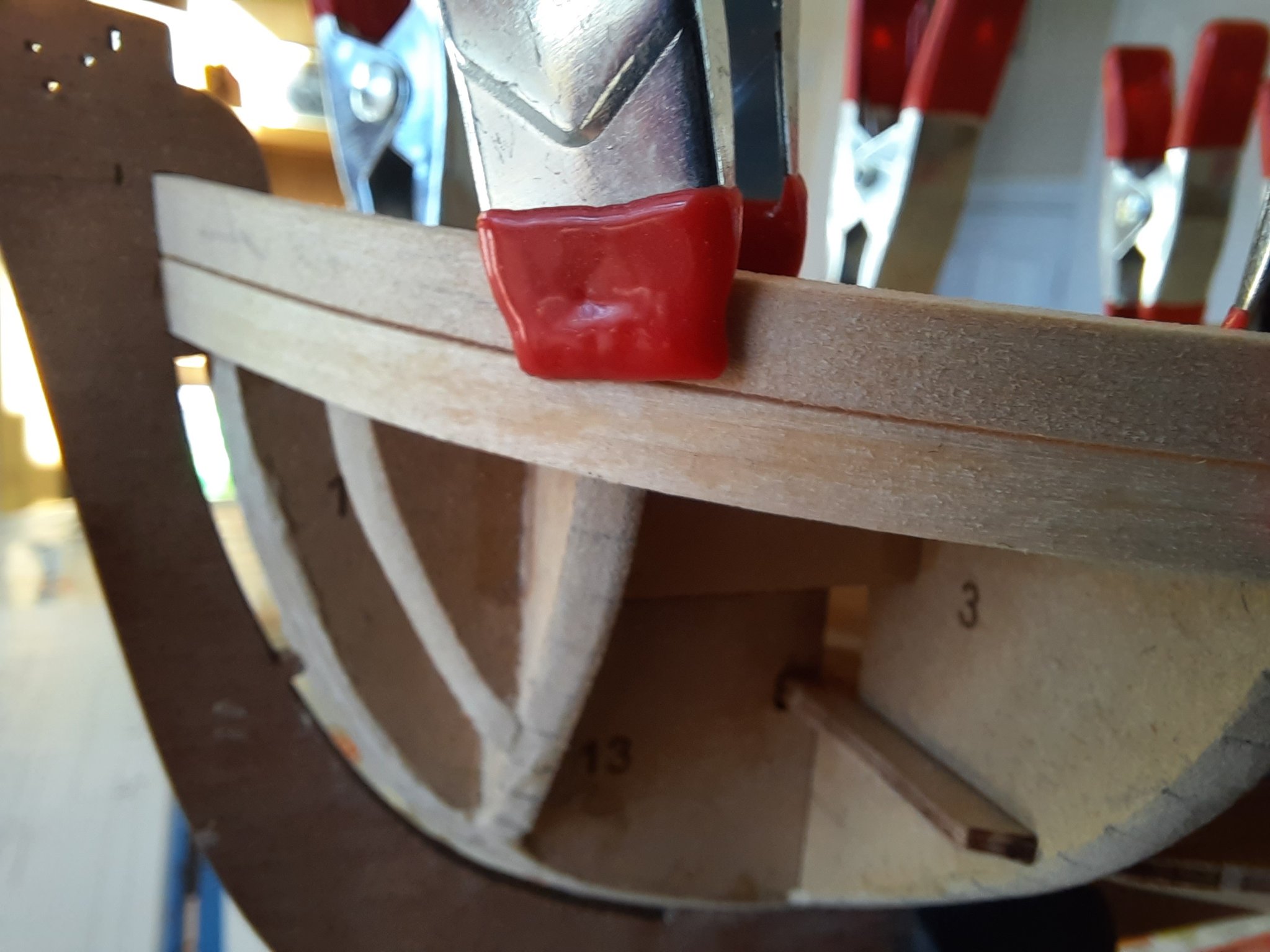
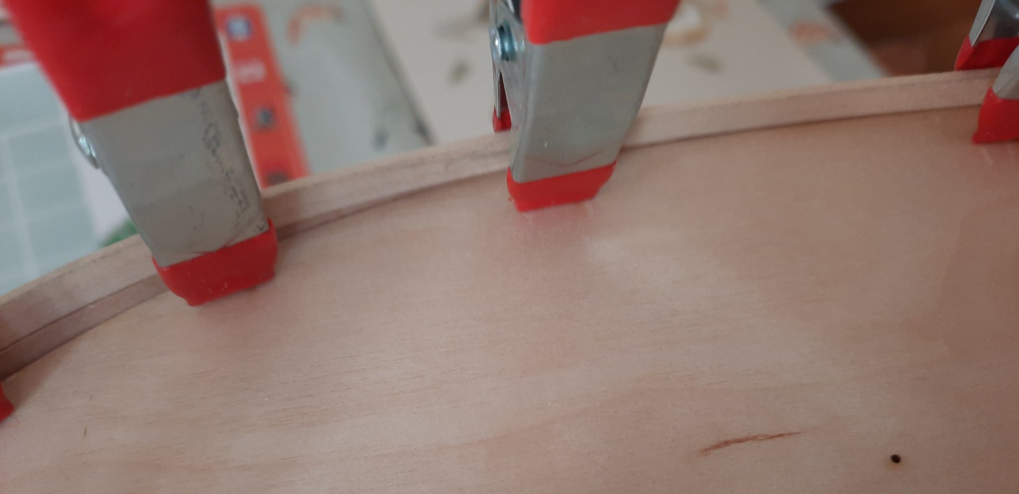
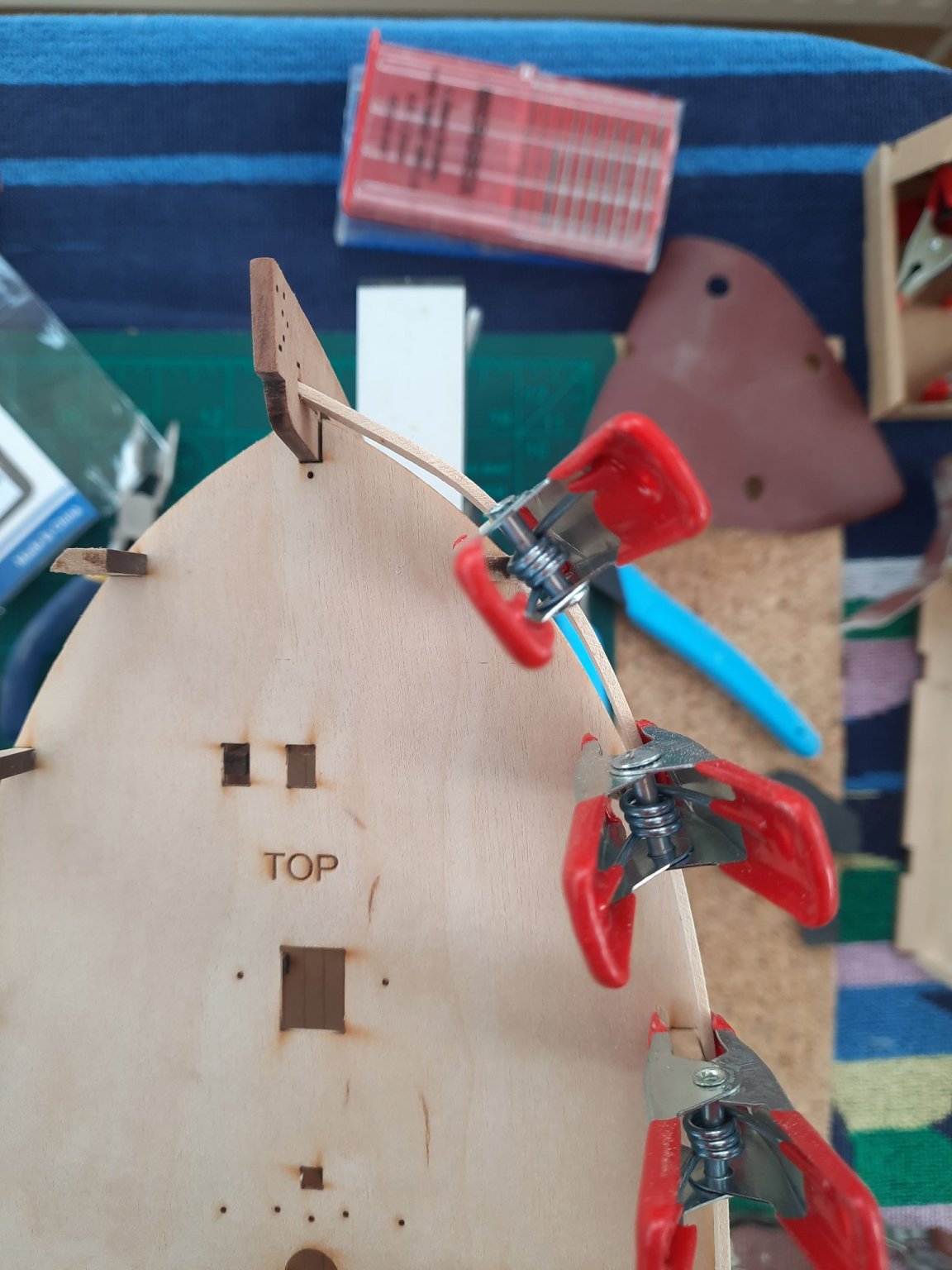
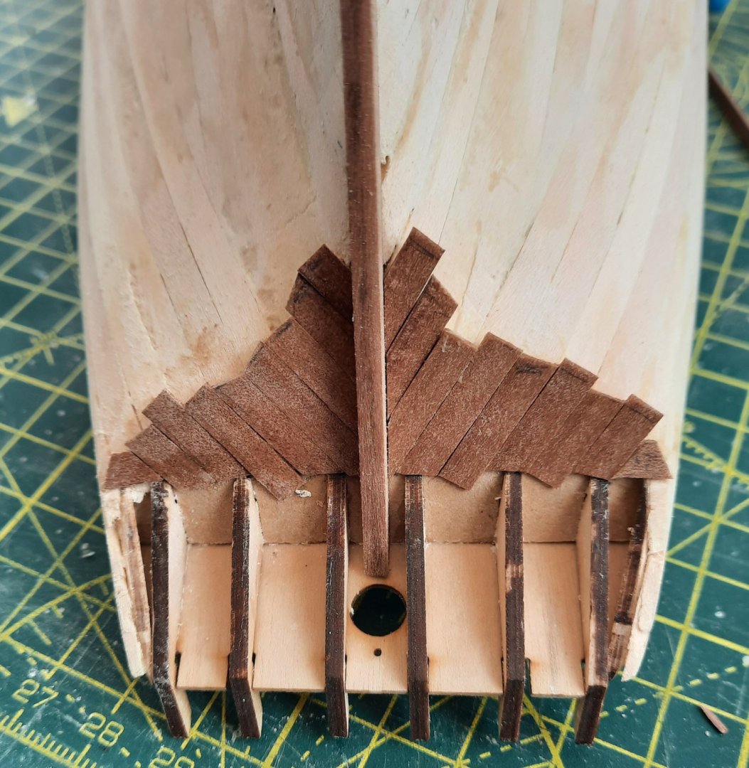
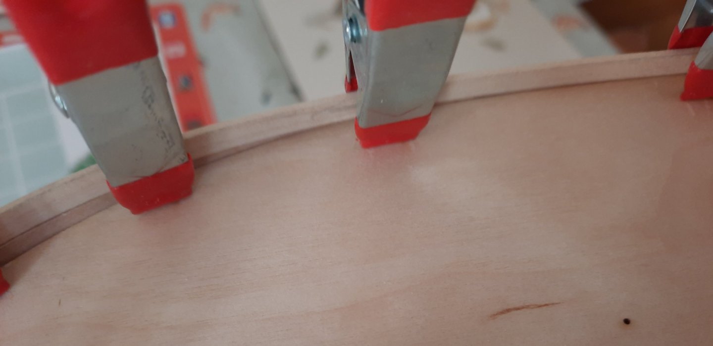
 Today I have sanded the 1st planking on the hull. I am now happy with how it is looking. I took my time to reduce the planking thickness around the stern area so the 2nd planking can be added and will align with the keel and stern post. I was able to utilise the sheets that the bulkheads were removed from as templates to double check the shaping of the hull around the bow area. This proved to be useful as I did note a couple of high and low spots which I was able to correct. I then moved on to adding the stern planking which sits below the stern counter pattern Stern counter planks fitted but not trimmed After trimming To complete the days activities I fitted the stern counter pattern. With the pattern dry fitted I marked and removed the excess material form the sides. I then added a chamfer to the lower edge so there would be a nice clean join with the lower stern counter planking. The two top 4mm planks have been soaked and bent in to place using clamps. It will now be left overnight to dry before they are glued in place. I did use the spacers provided with the kit to set the start point of the top plank from the stem post. I will be ready to start the 2nd planking phase in the morning.


- 160 replies
-
- 4
-

-
- Alert
- vanguard models
- (and 1 more)
-
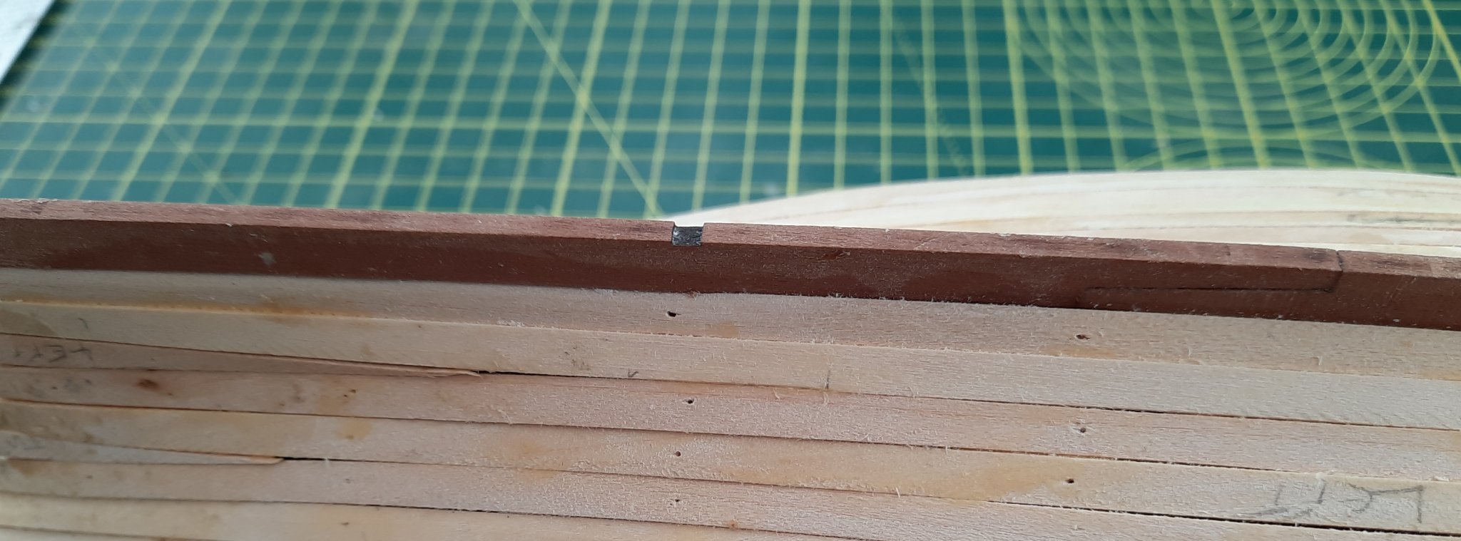
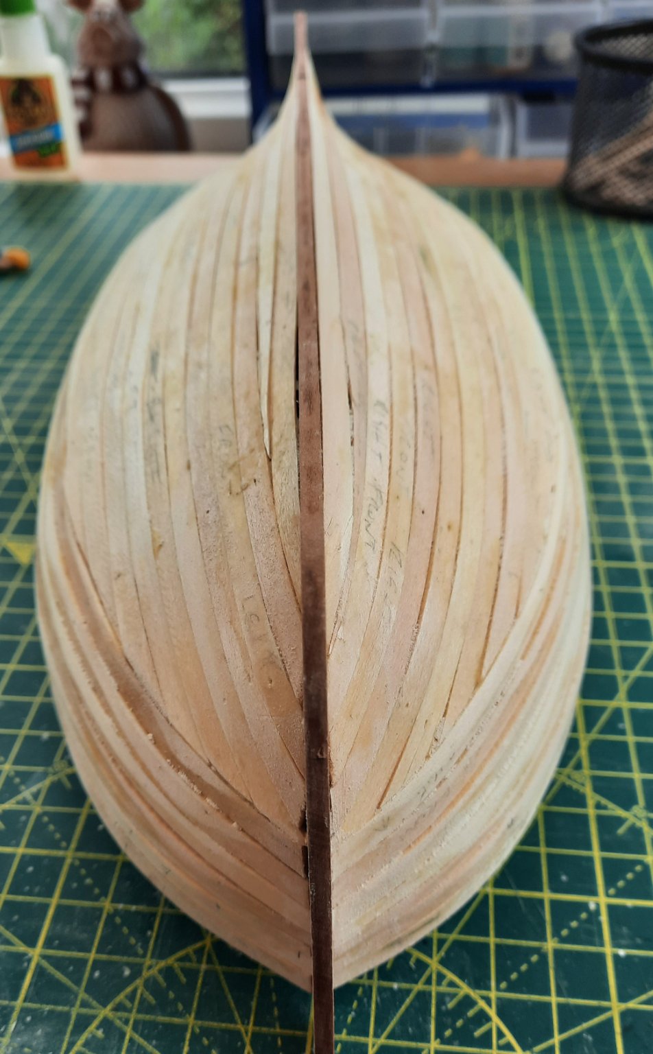
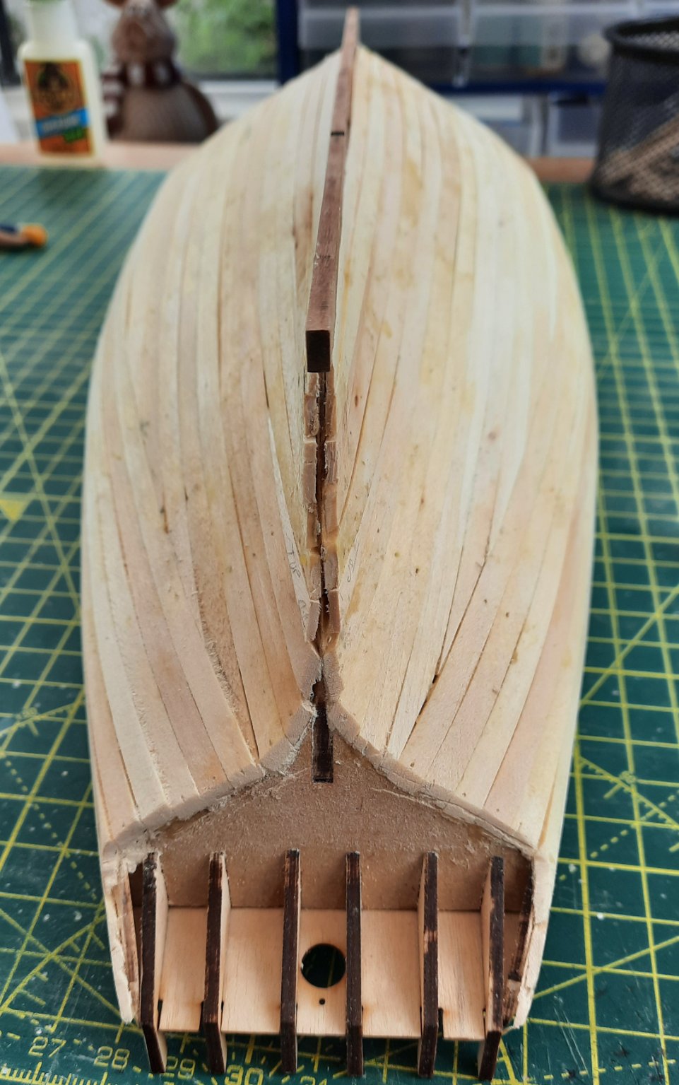
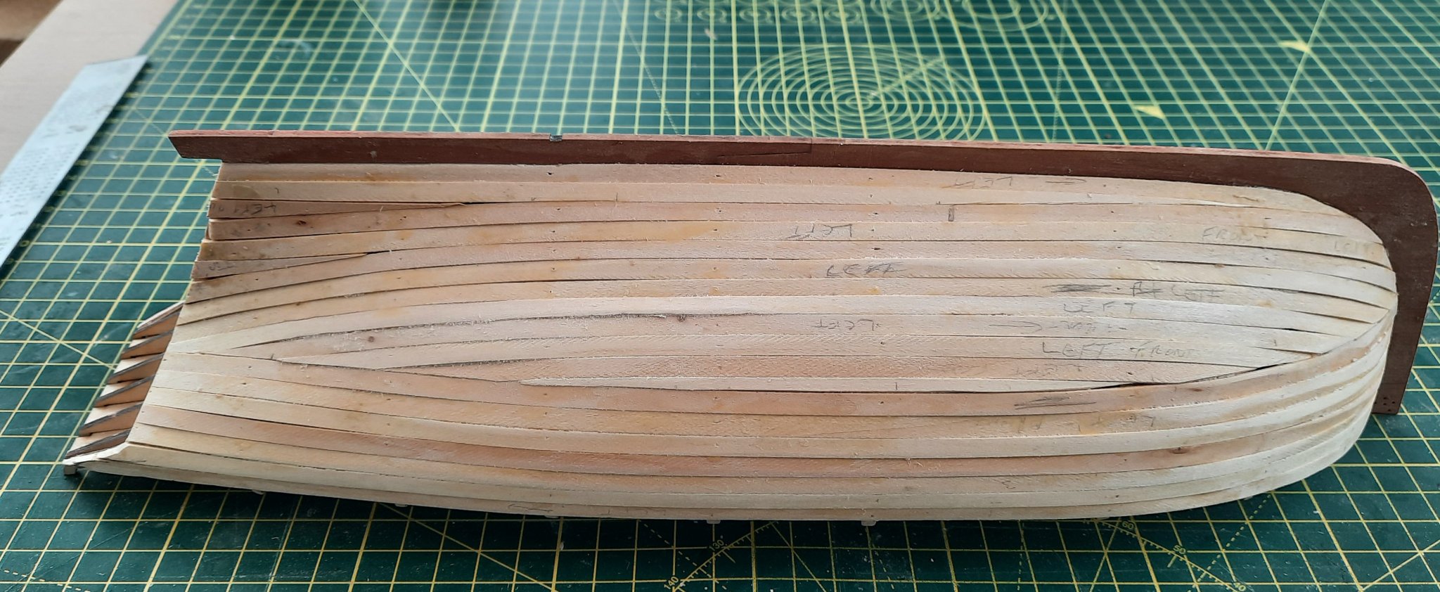
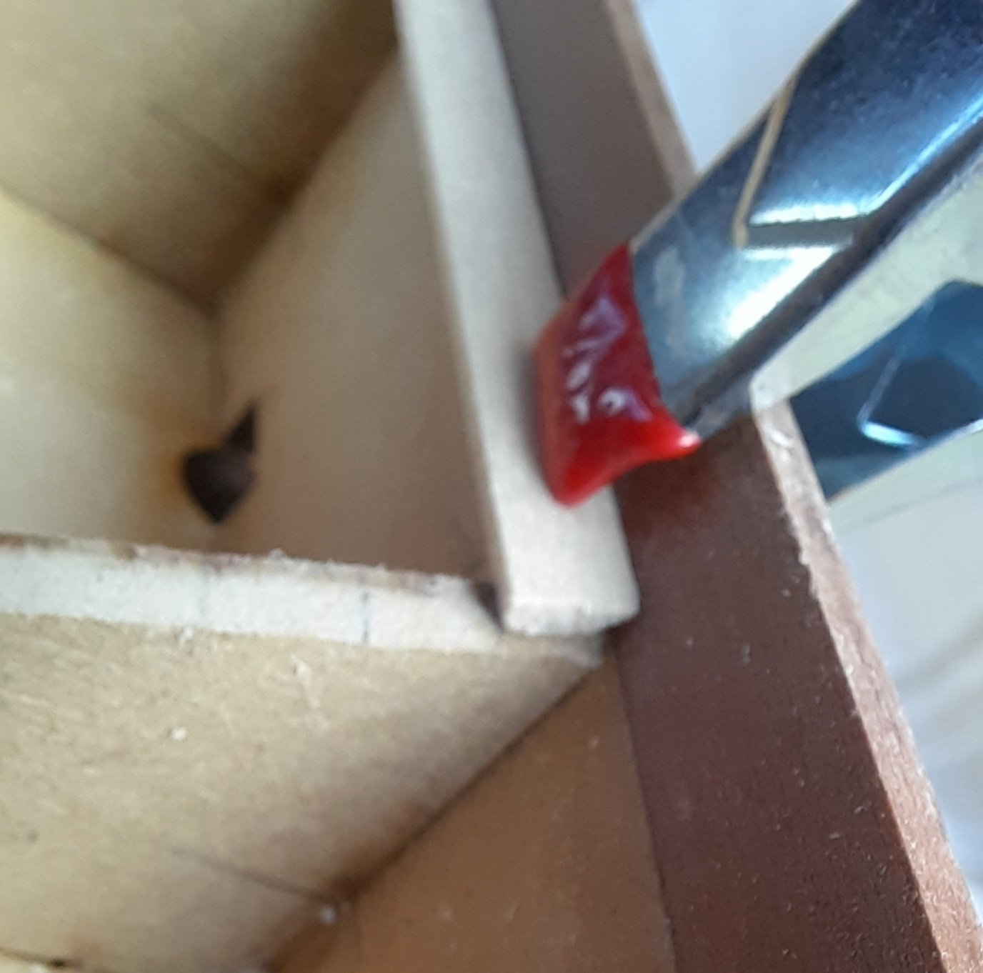
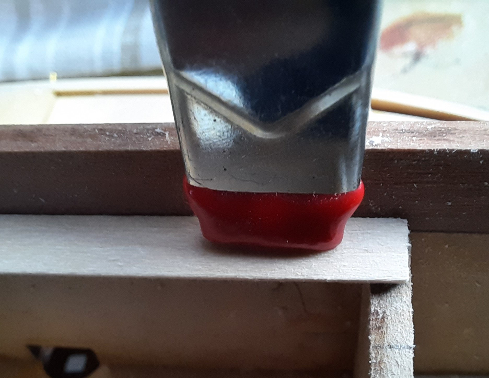
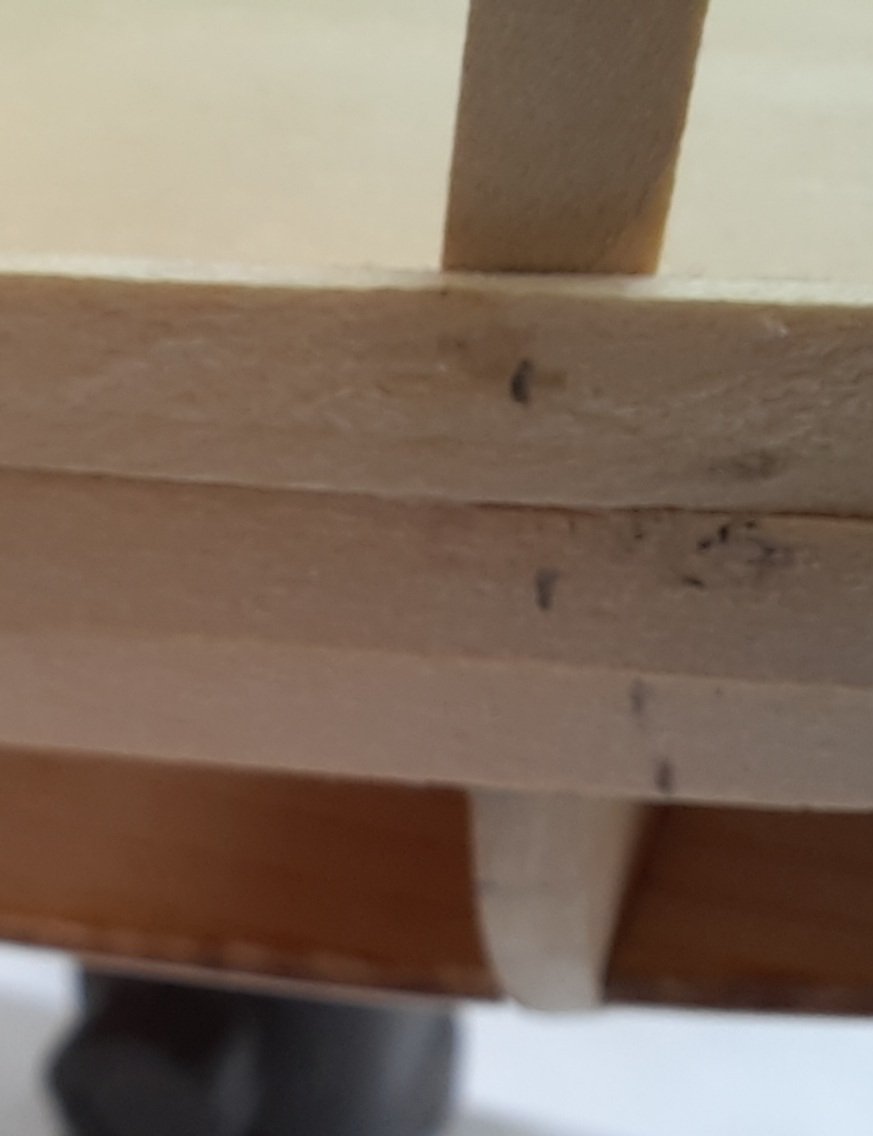
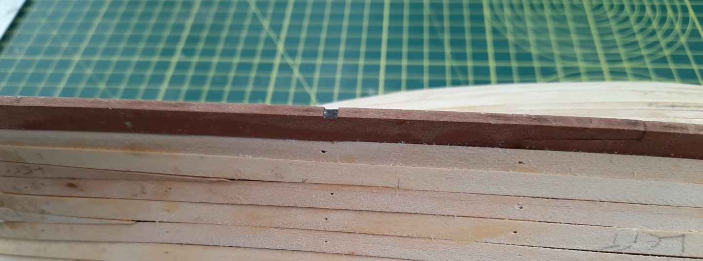
I have now completed the first planking and the hull is ready for sanding and filling. With regards to the filling (where necessary) I plan to use a mix made up of diluated pva (50/50) and Ronseal natural wood filler (a Jim Hatch concoction from his Sphinx build log). I found this mixture (made up of 50% pva and 50% wood filler) worked really well when I added a bit to an over faired section of a bulkhead. The following pictures of the planked hull may look a bit rough and ready and I could have done it better. However this is just a base layer for the 2nd planking. Once it has been sanded smooth (and filled where necessary) it will be fit for purpose. I opted not to bend the garboard plank as shown in other build logs. I have used the same method as my previous builds and provides the necessary base for the 2nd planking. I will probably use the same method with the 2nd planking as the planking will not be visible (below the waterline) once it has been sanded smooth and painted white. This is a view of the bow section, there are a few very small gaps to be filled This is the view of the stern. I have trimmed the excess plank material from the ends but it still needs some more work to get flush so the stern post can sit flush. Midships When fitting the plank next to the keel I did chamfer the edge to get a good fit. In the picture below I used a small piece of planking material to experiment with the chamfer. The test chamfer plank looks OK This shows the actual plank fitted with a chamfered edge.


- 160 replies
-
- 6
-
-
- Alert
- vanguard models
- (and 1 more)
-
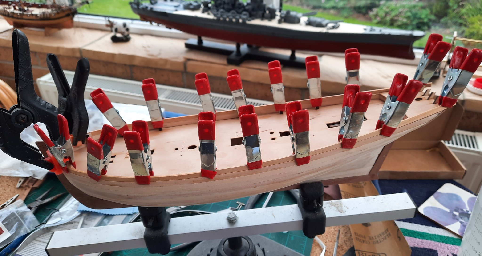
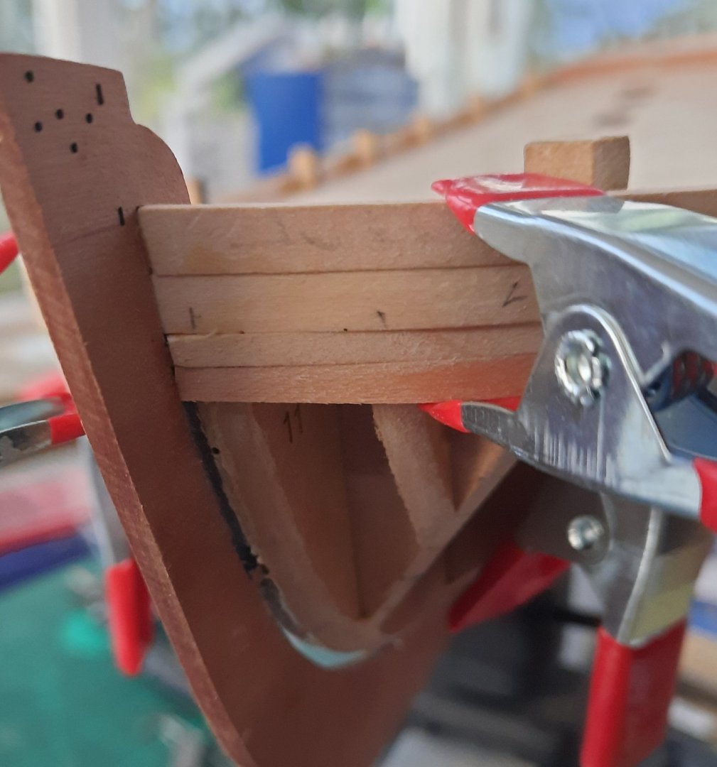
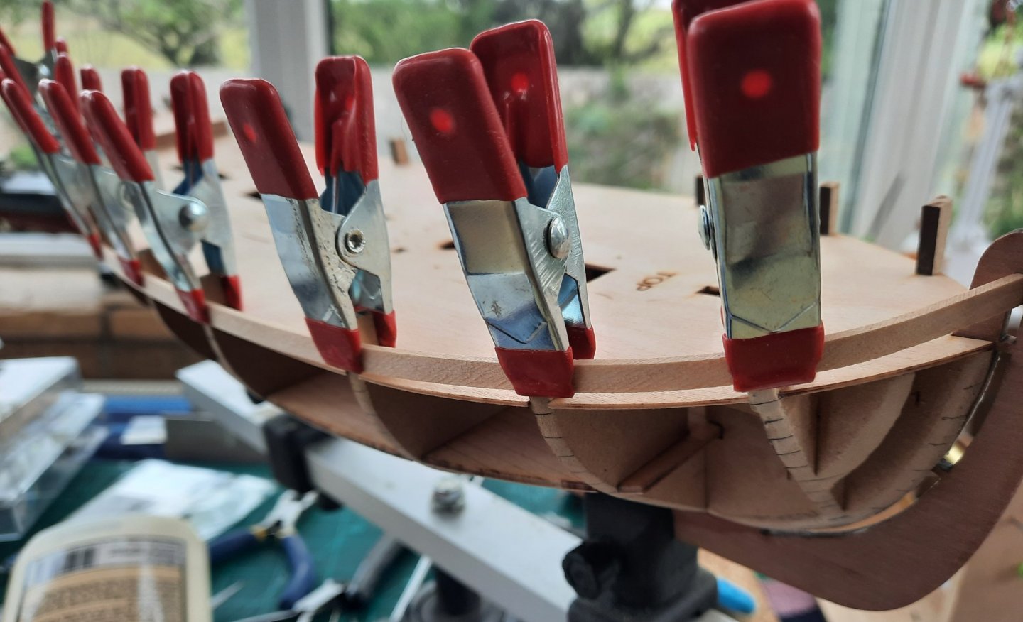
I have now glued the first three planks to the hull. They all went on without any problems. I used Titebond Original pva. I used clamps to hold the first two planks in place as the glue gripped. I used a mixture of clamps and pins went gluing the 3rd plank in place. I am reasonably happy with how the planks are looking so far. I have also bent and tapered (only required tapering at the bow end) the 4th plank. I have clamped the damp planks to the hull as I have now finished working on the model for the day so the planks should hold the shape when they have dried out. I intend to add a few more planks over the next few days. I will then add a garboard plank and start to plank upwards as well as downwards. In the following picture the first three planks have been glued and the 4th plank is clamped in place. The next picture show the bow area. A picture of the midship area Finally a picture of the stern area


- 160 replies
-
- 3
-
-
- Alert
- vanguard models
- (and 1 more)
-
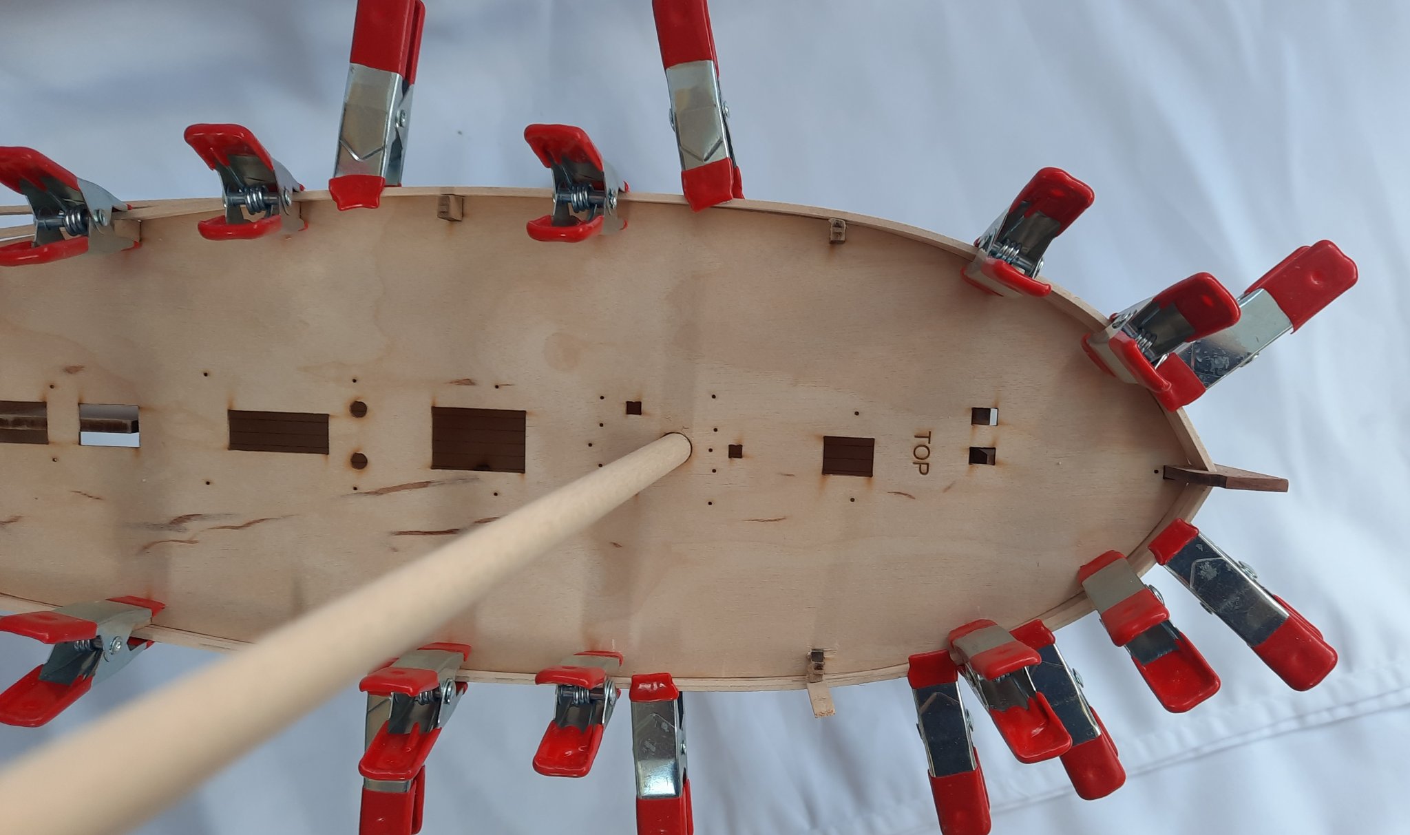
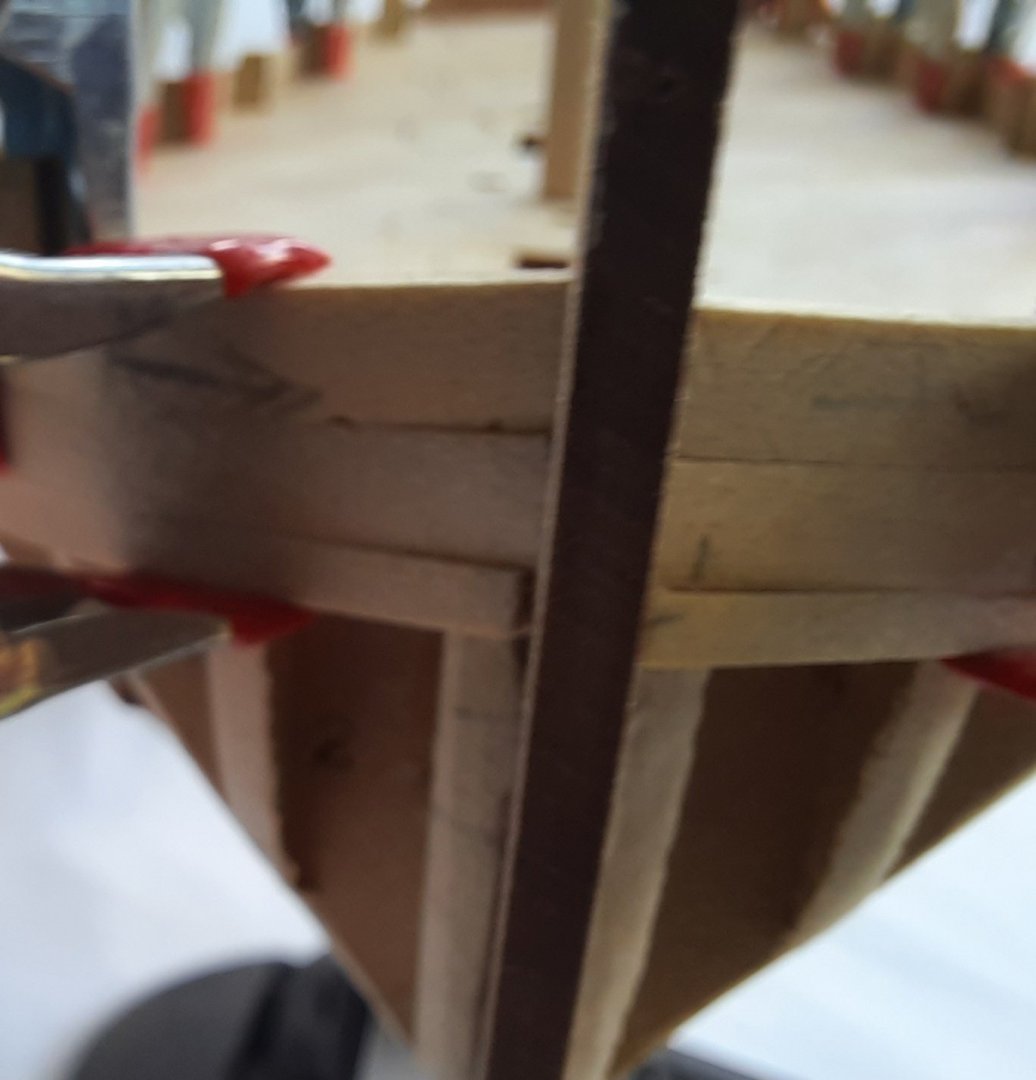
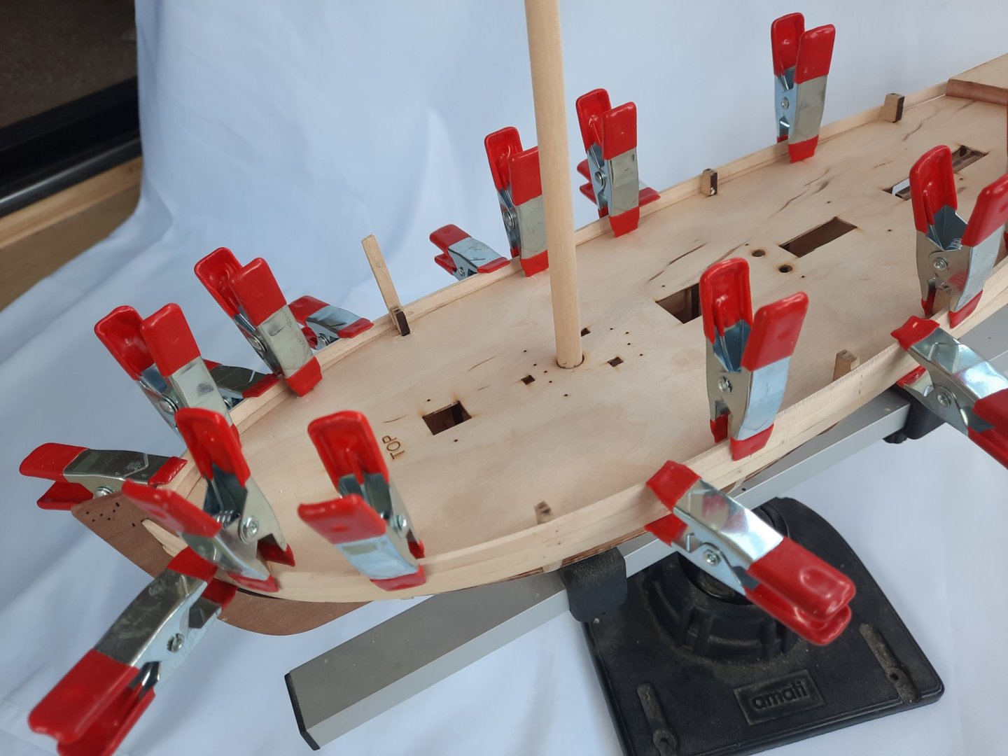
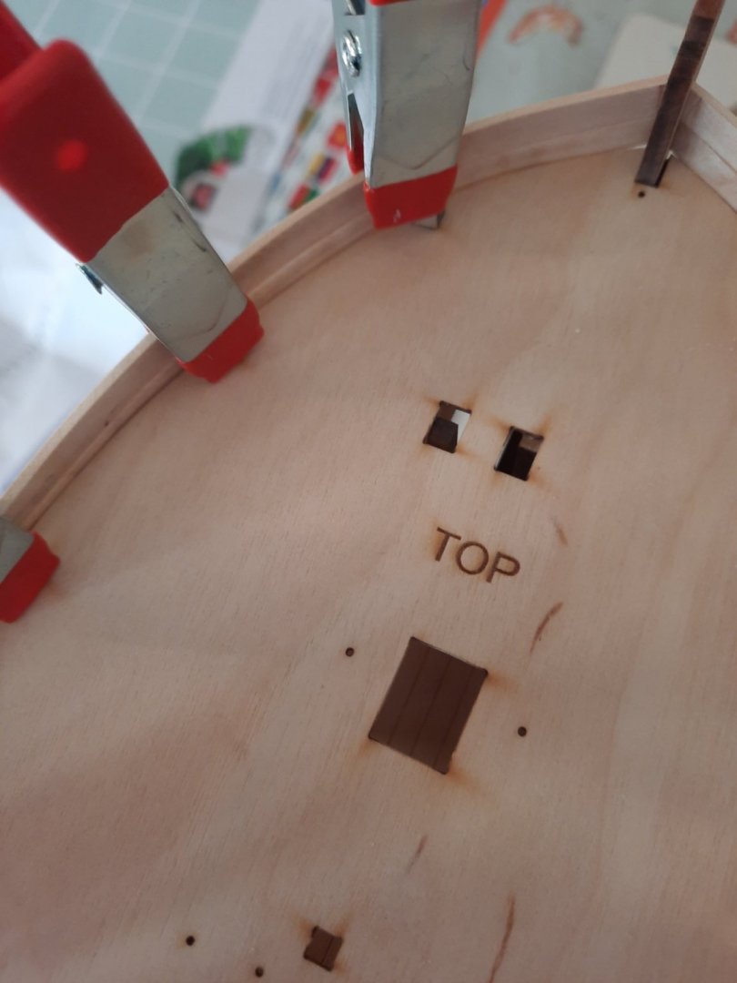
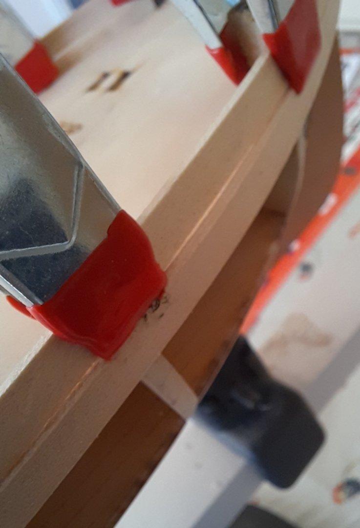
Sorry to bore you all with my continued start to the first planking. Before committing to the glue phase I decided to test fit the third plank on both sides. After adding the lateral (side) bend I noted the 3rd plank would need a taper around the bow section. Once I had marked, tapered and had the second bow shaping bend both the port and starboard 3rd planks were clamped in place to check the fit. The port side looks really good. The same is now true on the starboard side. The slight issue I had with the starboard side bowing at bulkhead 3 has now been resolved. The front on view of the bow section also looks good. The planks will be correctly positioned, when glued, to ensure they are tight up to the stem post as there is no rabbet slot for the third plank. I have also checked the main mast and it located through the deck hole in to the bulkhead slot very nicely. Finally this top view shows how the planking follows the shape of the deck, especially around the bow section. I am now very happy with how the planks look so I will now start to glue them in place forthwith.


- 160 replies
-
- 4
-
-
- Alert
- vanguard models
- (and 1 more)
-
Thanks and enjoy
-
Hello James She is looking really good. Your painting skills are excellent. Regards Glenn
- 355 replies
-
- 5
-
-
- vanguard models
- Sphinx
- (and 1 more)
-
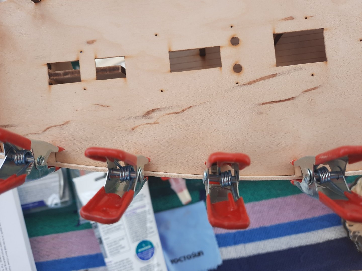
Following on from my last post I spent a bit more time this afternoon fairing the bow (bulkhead 2). I then bent the first two planks for both the port and starboard sides. I started with the lateral (side bend) and then added the bend that followed shape around the bow. I then clamped both sets of planks to the hull. As can be seen in the photo below the port side planking is a perfect fit This is a close up of the port side bow area. The planks are a nice tight fit (only dry fitted) This picture shows the port side inner bulwarks are nice and flush. When looking at the starboard side the problem with bulkhead 2 has now been fully resolved however I did notice a slight issue with the fitting around bulkhead 3. I will need to fair bulkhead 3 a tad more before gluing them in place. This picture (which is slightly out of focus) shows the slight bulge at bulkhead 3 (starboard side). This picture shows the starboard side inner bulwarks, as can seen the lower plank is not flush with the upper plank around bulkhead 3. The time and effort I have spent fairing and test fitting the first two planks for this build has really paid dividends. In the past I would have probably gone ahead and glued the planks in place and then either sanded or used wood filler to correct the problems.


- 160 replies
-
- 5
-
-
- Alert
- vanguard models
- (and 1 more)
-
Thanks. I find it much better when I take my time to check how the parts fit together before I glue them in place.
- 160 replies
-
- 2
-
-
- Alert
- vanguard models
- (and 1 more)
-
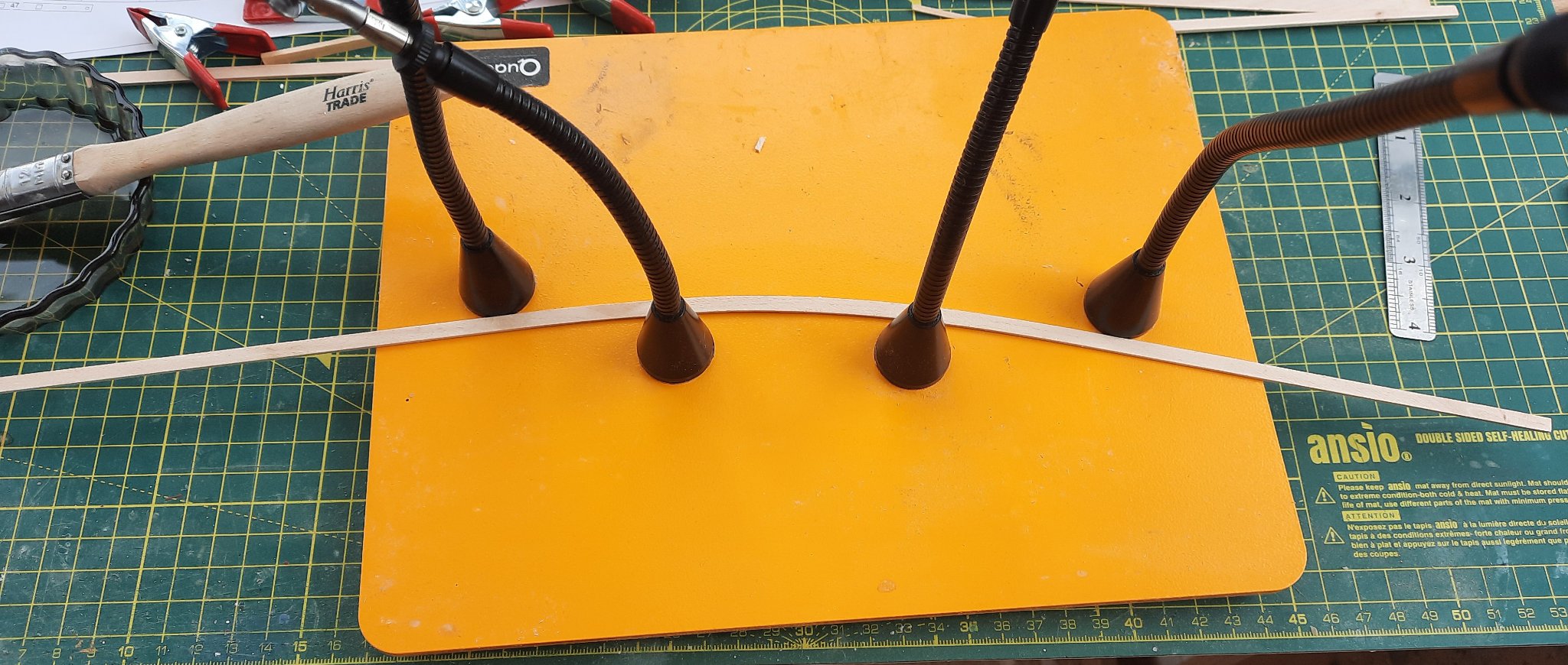
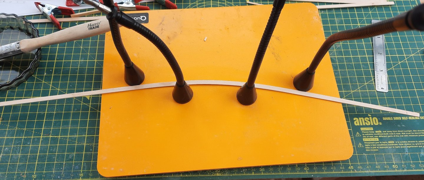
A very useful tool.
-
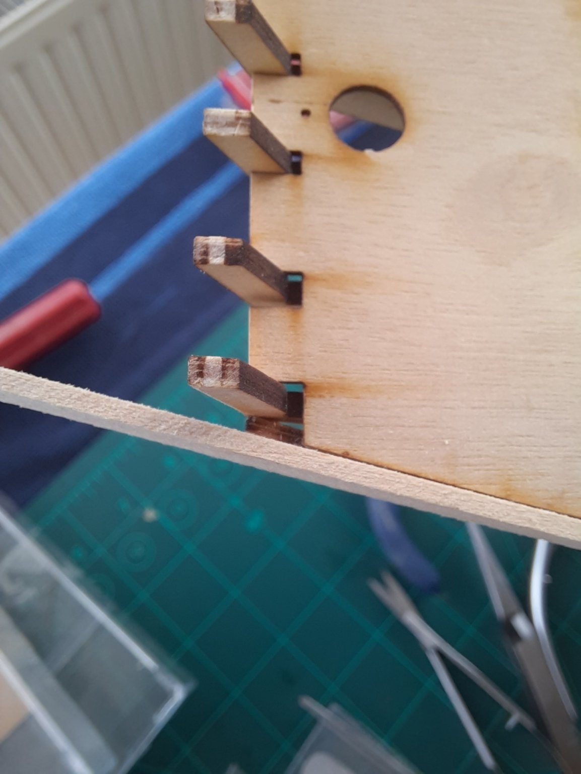
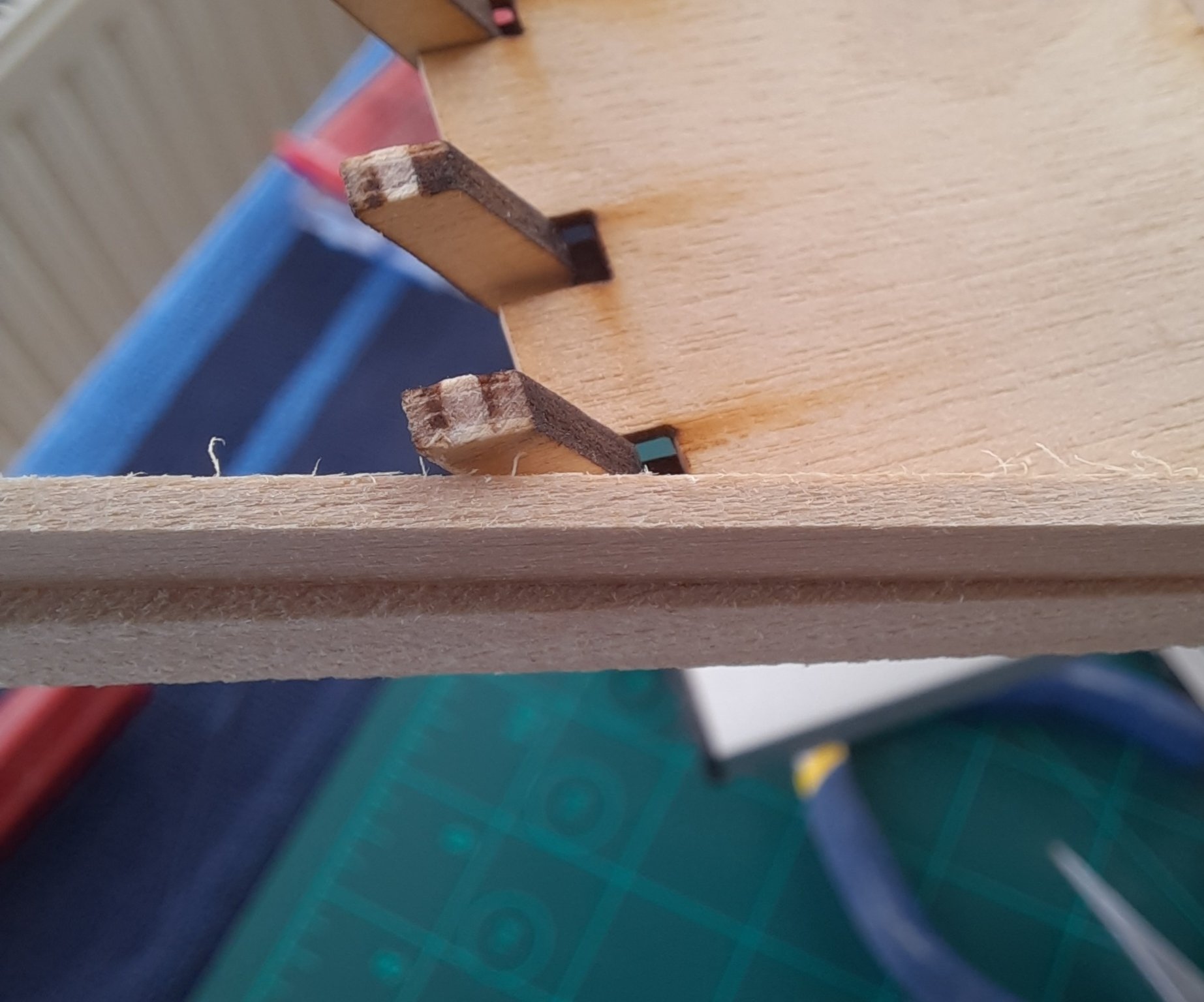
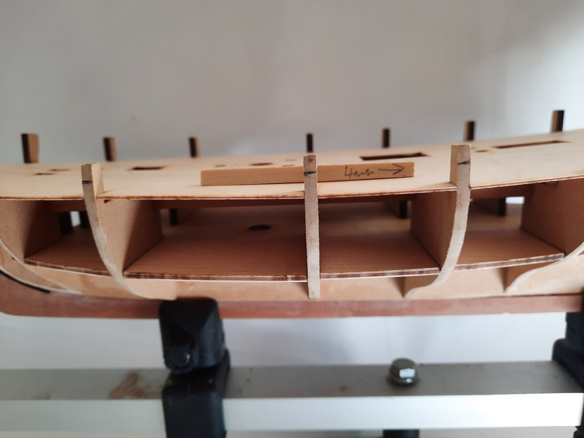
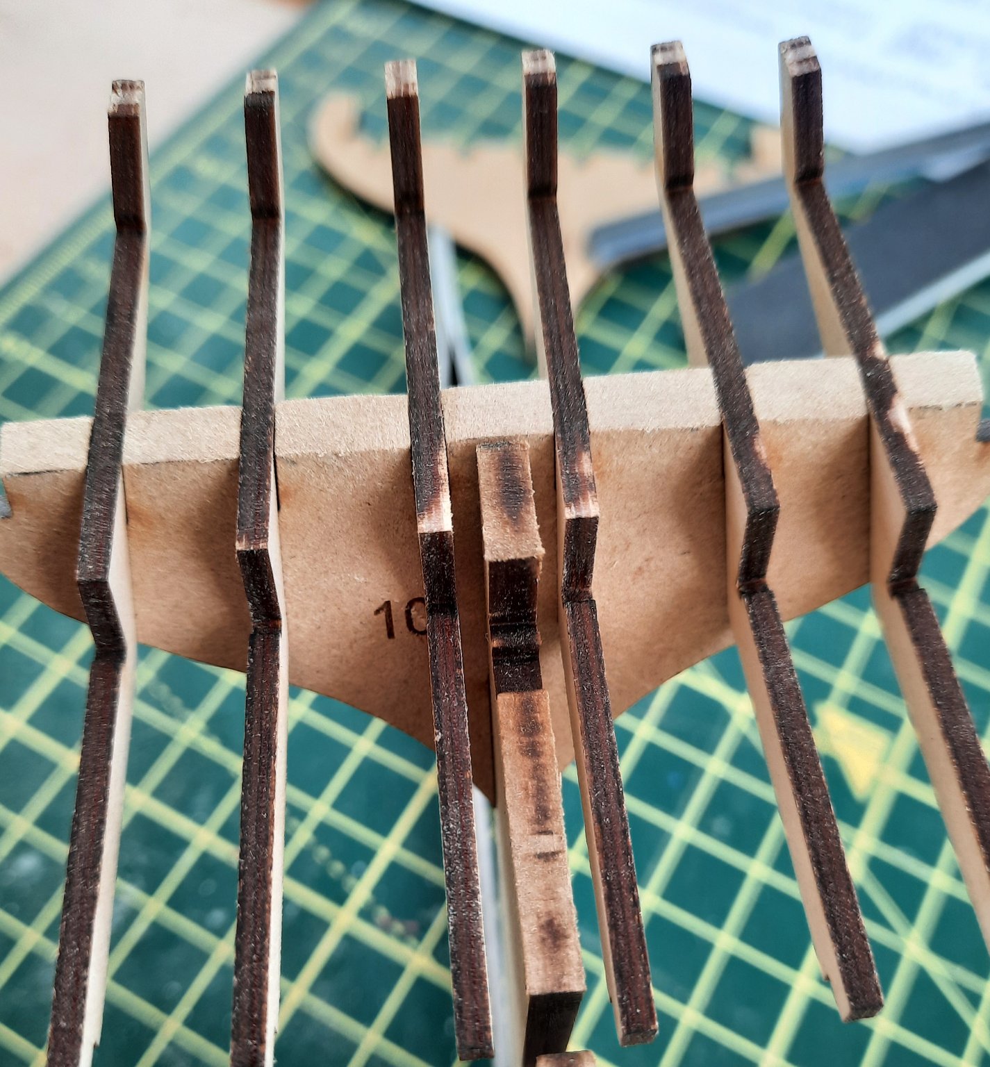
Today I have been looking at starting the 1st planking. I discovered the quad hands had another use as a template for lateral (side) bending the planks. After soaking the plank I positioned it on the quad hands base, using the quad hands to set the bend angle. Once the plank had dried out the bent plank was test fitted against the hull, 4mm down from the top edge. I was extremely pleased with how the plank laid against the various bulkheads. On closer examination I noted that there was a slight bowing issue with bulkhead 2 which is easy to correct with a bit more sanding. I also noted that I need to fair the stern filler piece (20) a bit more so the plank can sit flush with the outer stern frame piece (19) As can be seen in the photo below this is not the case. When the top 4mm top plank is test fitted the problem can clearly be seen. There is plenty of plank material to sand smooth but I need to sand the filler back a bit more however.


- 160 replies
-
- 4
-
-
- Alert
- vanguard models
- (and 1 more)
-
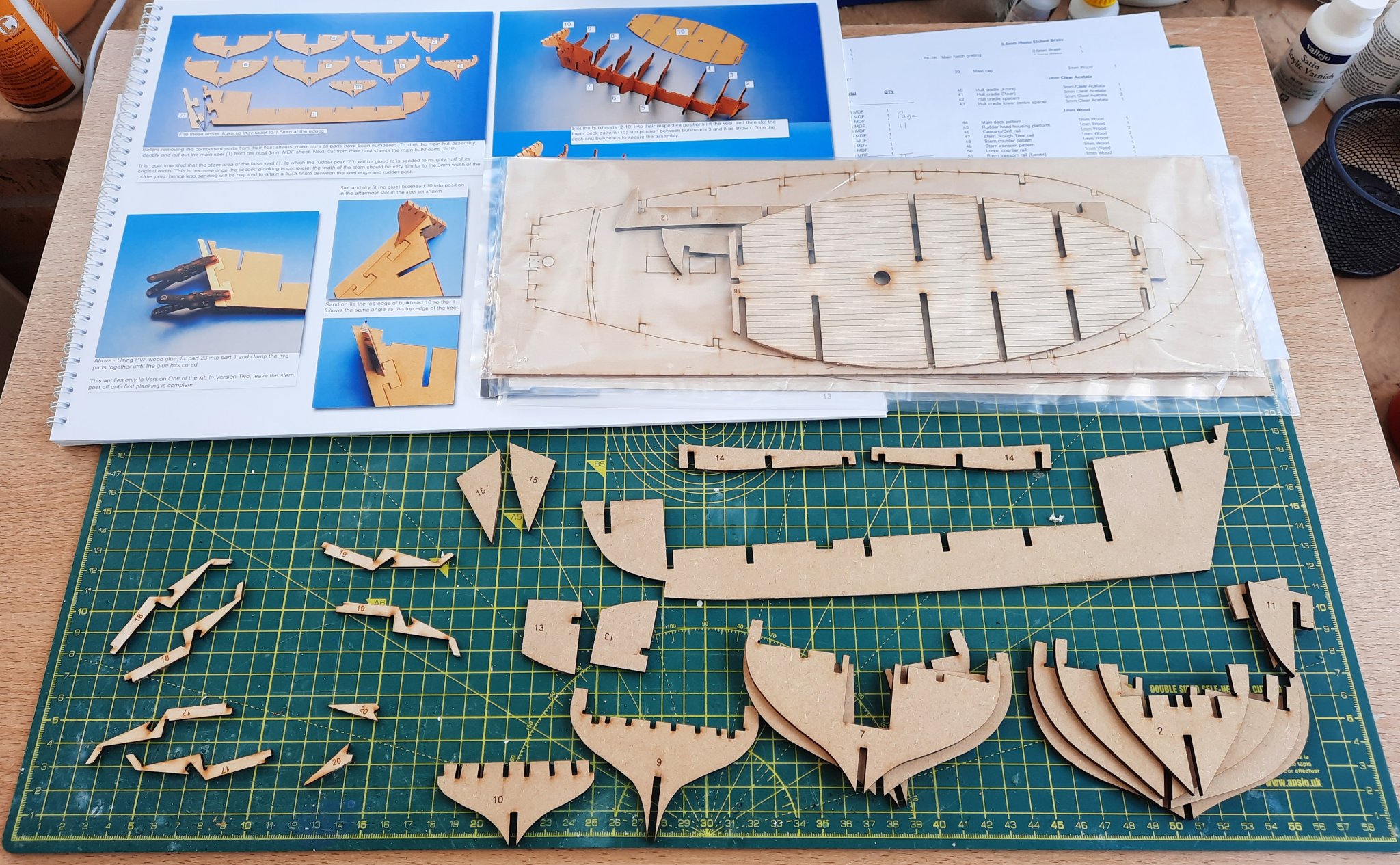
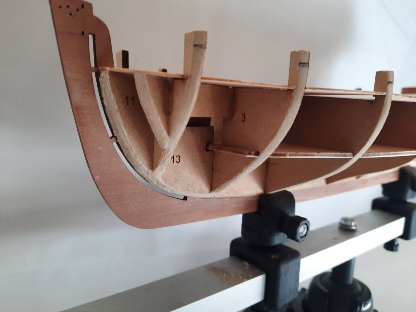
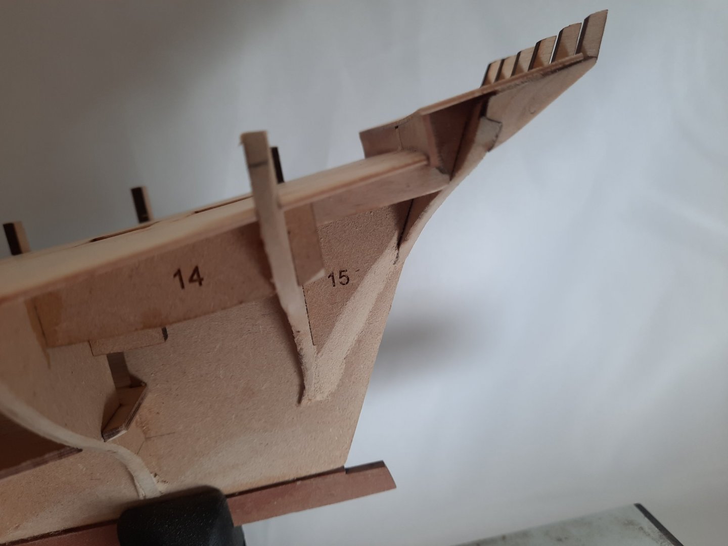
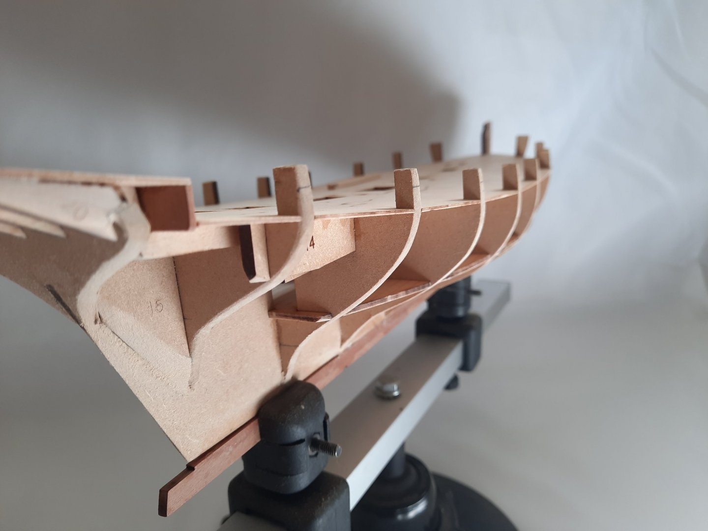
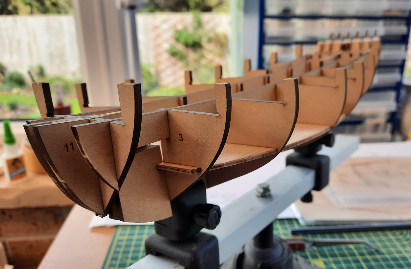
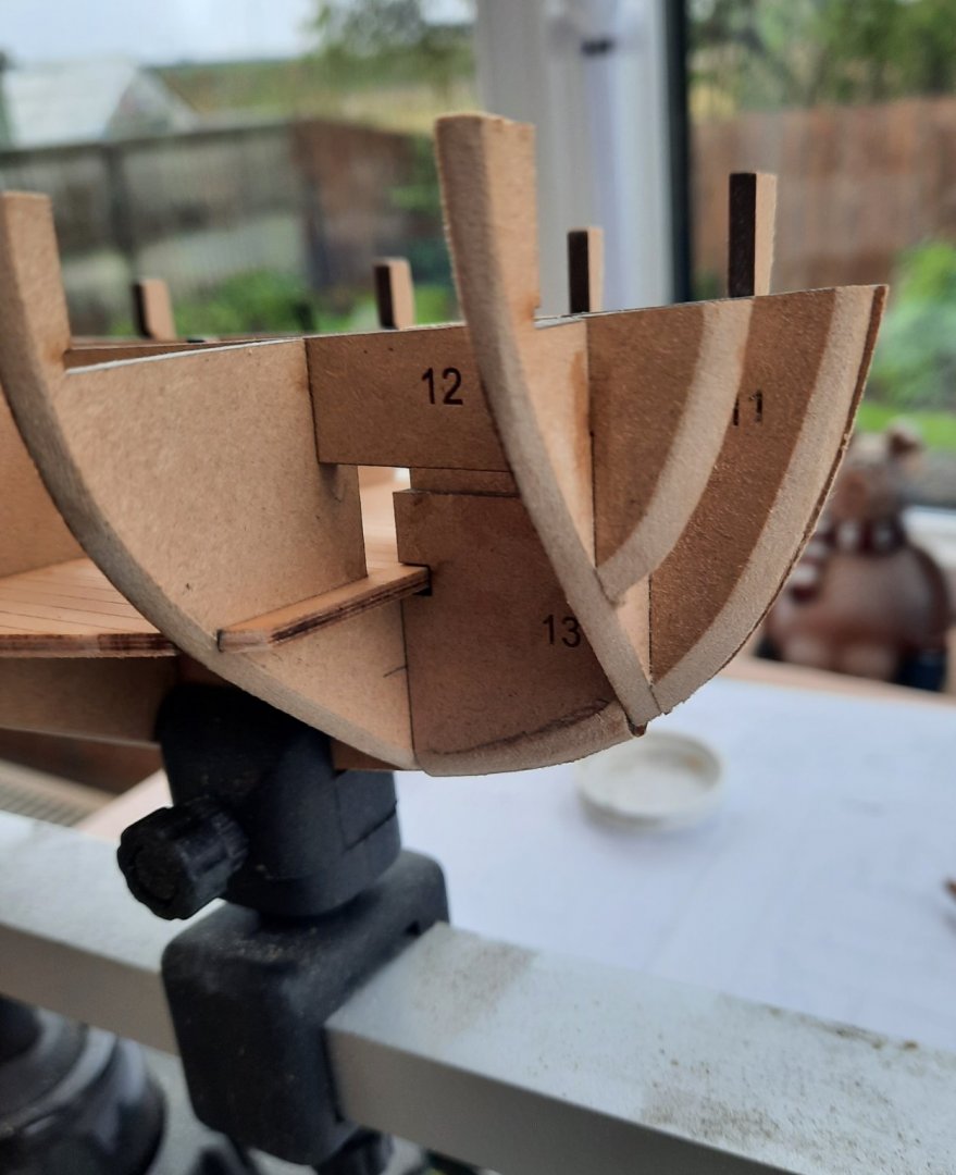
I have now completed the basic hull assembly phase and the Cutter Alert is ready for the first planking. I spent quite a bit of time fairing the bulkheads and I am now happy with how my test planks are laying. In particular bulkheads 4 to 2, and fillers pieces 11, 12 and 13 needed plenty of sanding. Also bulkheads 7 to 9 and filler piece15 required a lot of attention before I was happy with how the garboard plank would fit. Filler piece 20 also required a lot of sanding to make sure it ran flush with the side of the Rudder head housing platform. Once I was happy with the fairing I went ahead and fitted the front stem keel and the rear keel pattern. I did notice the rabbet slot in the front stem would only take the 1st plank. I did experiment with tapering the width of the 1st plank so the 2nd plank could also be located in the rabbet. Although I concluded this would be possible I felt it would be too much additional work and providing I take my time with the 2nd planking I do not think it will be an issue. Picture of the Front Stem Keel piece. Picture of the stern area Picture of the stern showing the beading Using a small piece of 4mm wide planking material I marked the top line position for the first plank. Checking the length of each bulkhead I have estimated the following number of planks will be required. 8 planks Bow 12 planks Bulkhead 2 15 planks Bulkhead 3 16.5 planks Bulkhead 4 18 planks Bulkhead 5 18 planks Bulkhead 6 16 planks Bulkhead 7 16 planks Bulkhead 8 17 planks Bulkhead 9 18 planks Bulkhead 10

- 160 replies
-
- 4
-
-
- Alert
- vanguard models
- (and 1 more)
-
Thanks Gunther It took me 6 months to build and I spent around 3 to 4 hours per day on the build.
- 382 replies
-
- 1
-
-
- Vanguard Models
- Duchess of Kingston
- (and 1 more)
-
Hello Richard Very happy she is finished and she is sitting proud in our dining room so she continues to be a feast for the eyes.
-
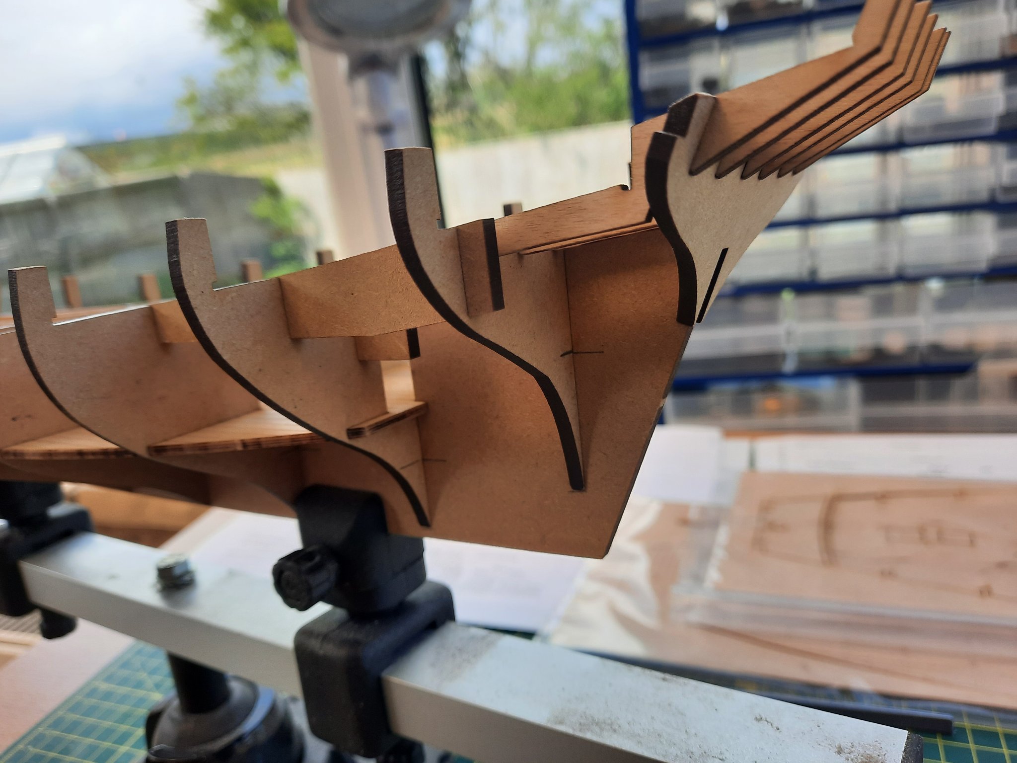
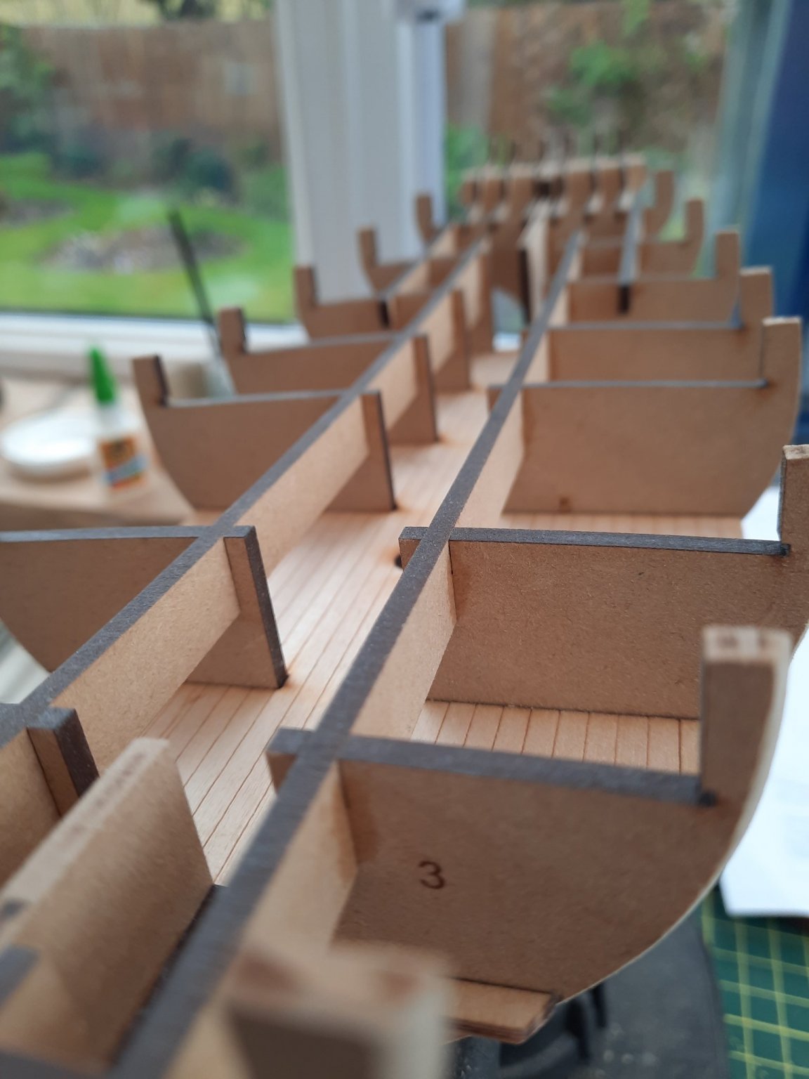
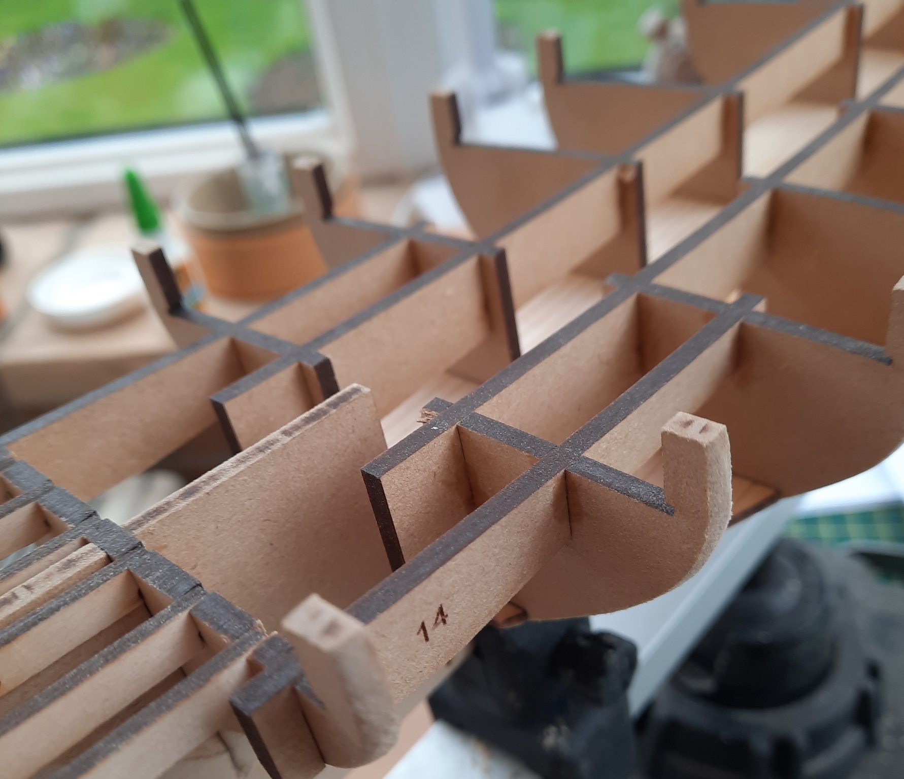
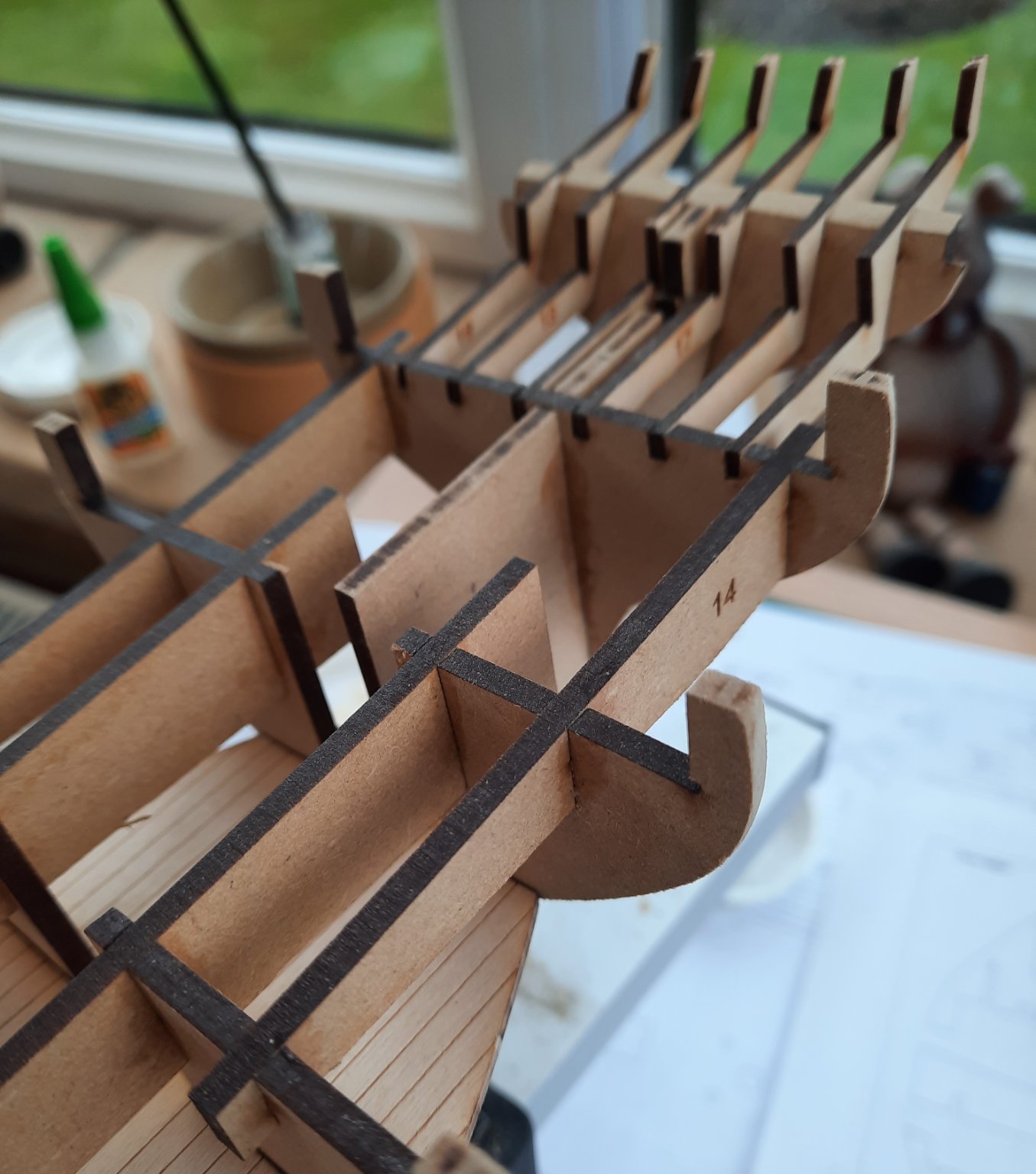
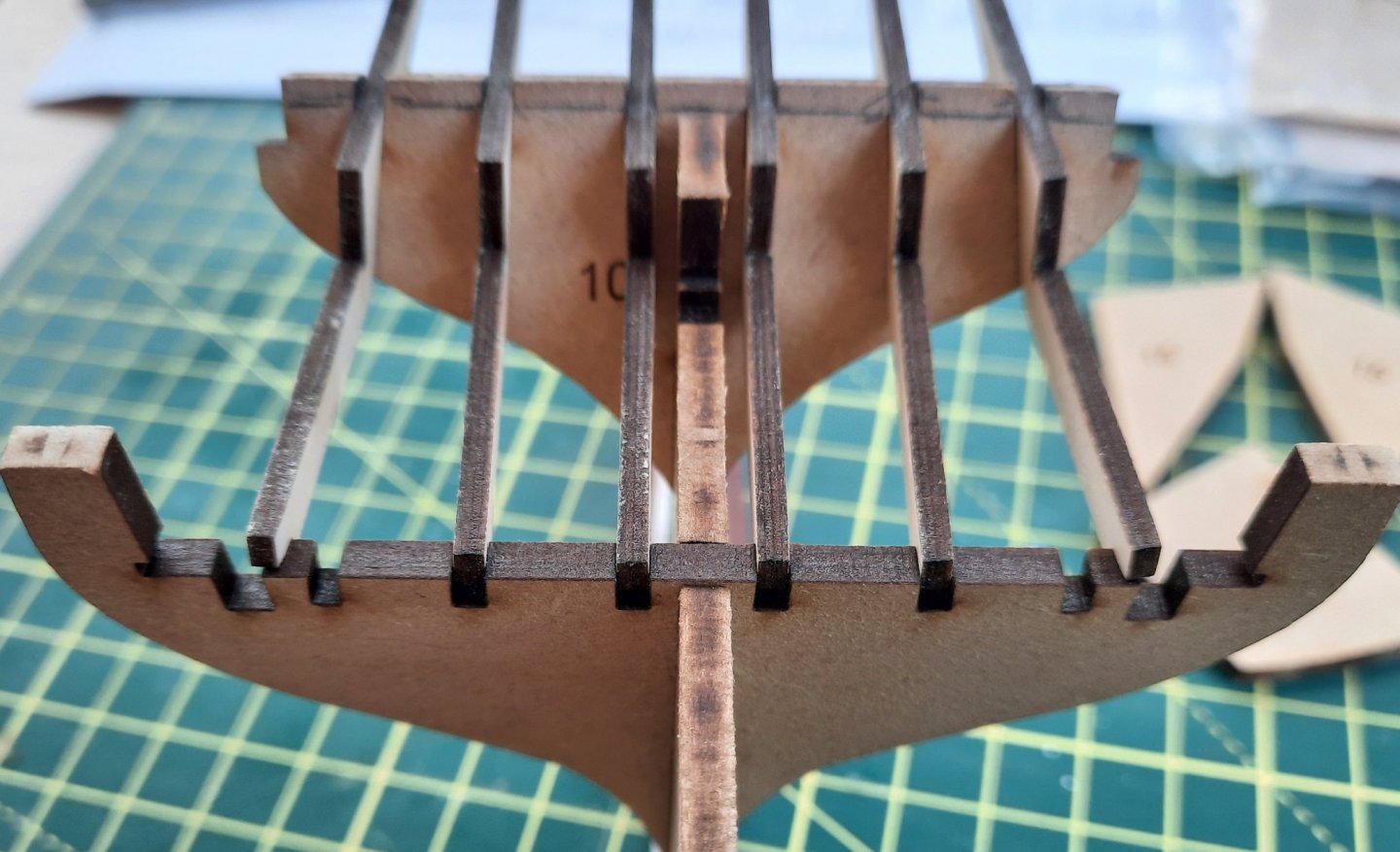
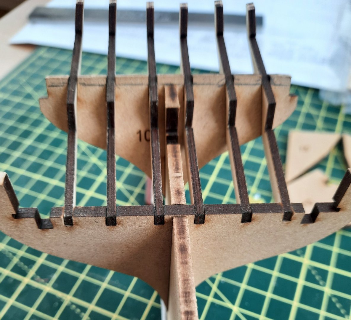
I have been cracking on with the hull assembly today and have made good progress. I started off with a full dry fit of the various items. I was pleased with how well everything fitted. When fitting the bulkheads, as can be seen in the next photo, I like make pencil marks as an indication that they are fully seated. Next I drew the beading line on the keel. To help ensure I remove an equal amount of the keel during the beading process I added a thin tape strip along the edge as a guide. Next I faired the bulkheads, support strips and fillers and then assembled the hull. I will complete the fairing process using planks to check the various contact areas. This is a picture of the bow section This picture shows the main support strips in place This picture shows the stern support strips in place. This picture shows the stern filler piece in place This is another picture showing the stern area This final picture shows the stern frame which are only dry fitted but once glued in place I can then fit the main deck next along with the two two rudder platform bulkheads and rudder head housing platform.


- 160 replies
-
- 6
-
-
- Alert
- vanguard models
- (and 1 more)
-
Hello Derek I would to like get this model built before The Sphinx is released later this year. Also bashing wood again makes a nice change after many weeks of rigging
-
Many thanks. If you could see some of the errors I've made, especially with some of my rigging then the bar is not set that high🤣
-
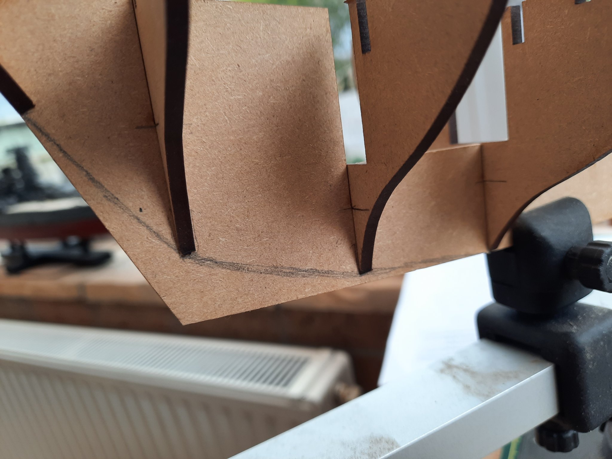
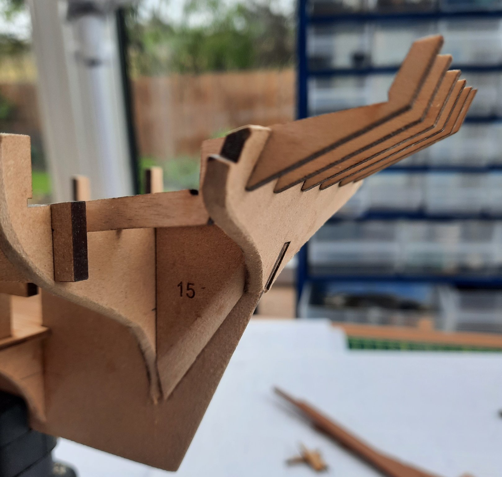
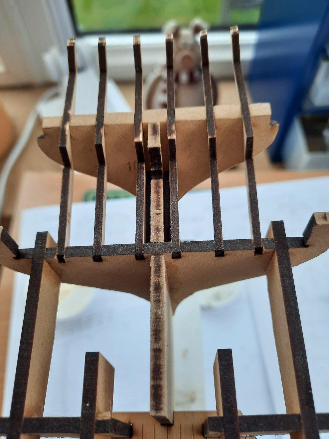
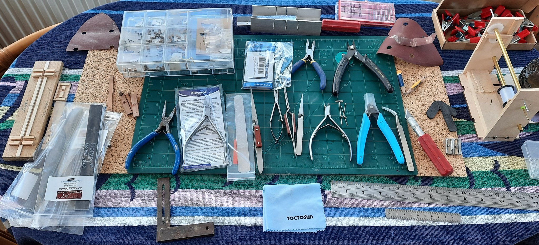
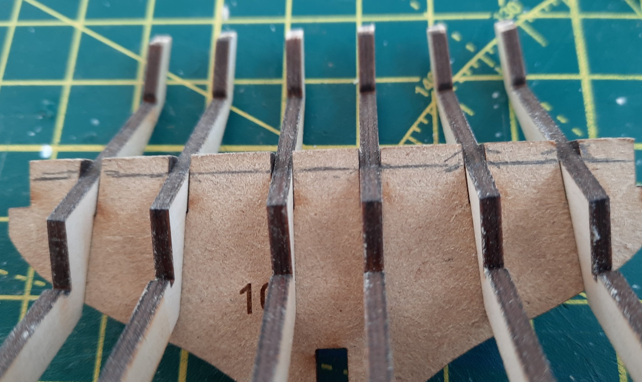
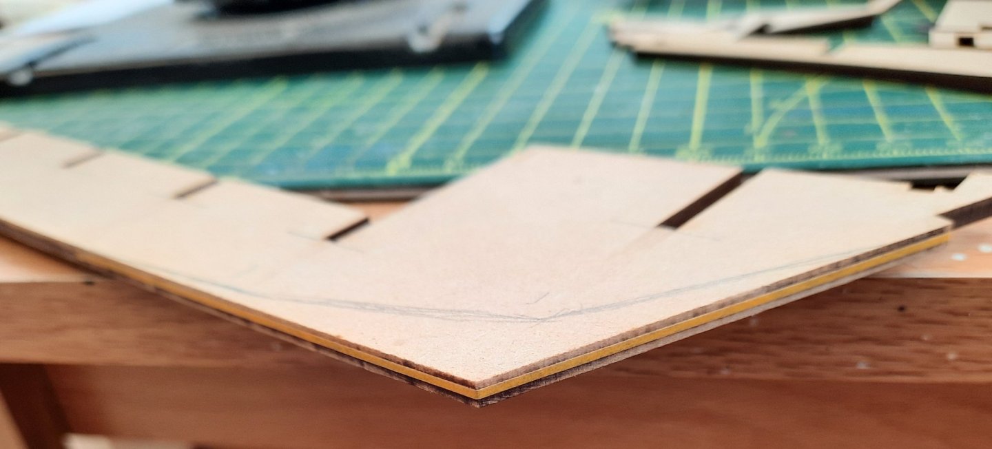
Now that I have completed the Duchess of Kingston build the shipyard required a good tidy up ready for the next occupant. A selection of tools have been layout out in readiness for the Cutter Alert The Cutter Alert has now moved into the shipyard and is ready for the hull assembly phase. I do like to test fit parts to see if there are any potential problems. When fitting the inner, middle and outer stern frames to bulkhead 10 and 9 there did seem a slight alignment issue with the two outer stern frames, as shown in the photo below. With a little bit of gentle persuasion the outer stern frames could be fitted in the bulkhead 9 slots. The first task is to bevel the top edge of bulkhead 10 so it follows the same angle as the top edge of the keel. With the stern frames positioned in bulkhead 10 I marked the position of top edge of the keel on bulkhead 10 to make the sanding task easier. Using my sanding stick it did not take too much effort to shape the top of bulkhead 10. As can be seen in the photo below the edge between the two inner stern frames still requires a tad more sanding.


- 160 replies
-
- 4
-
-
- Alert
- vanguard models
- (and 1 more)
-
Looking very good. It is another master class of your building skills.
- 355 replies
-
- 4
-
-
- vanguard models
- Sphinx
- (and 1 more)