Glenn-UK
-
Posts
2,630 -
Joined
-
Last visited
Content Type
Profiles
Forums
Gallery
Events
Everything posted by Glenn-UK
-
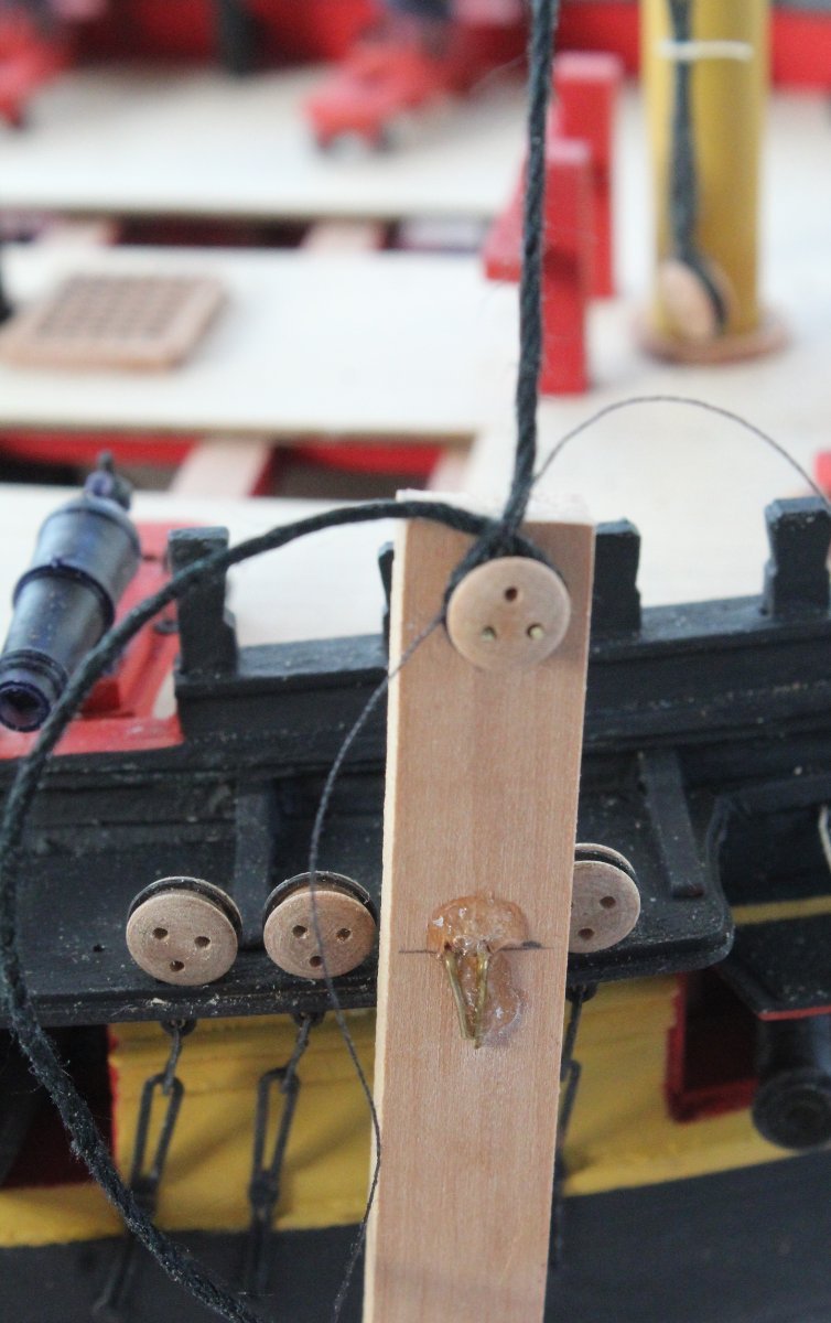
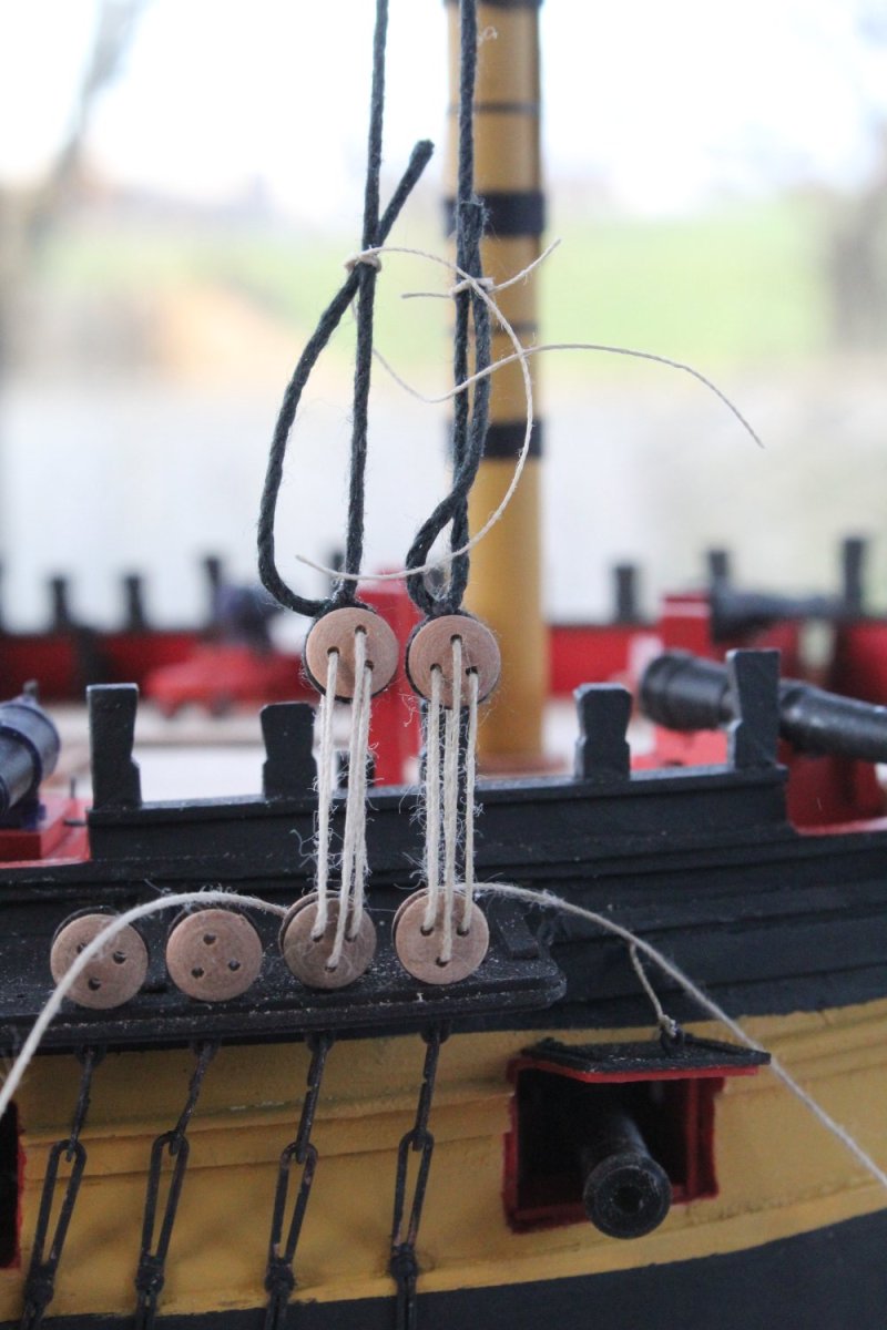
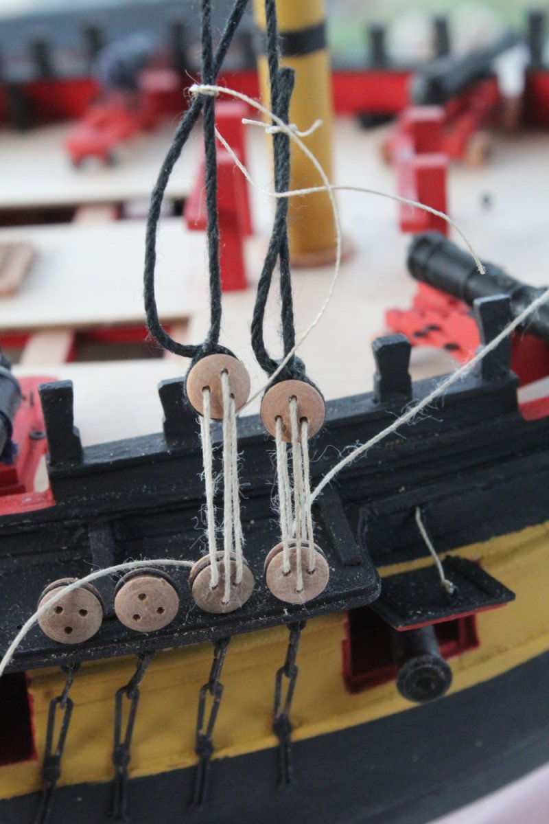
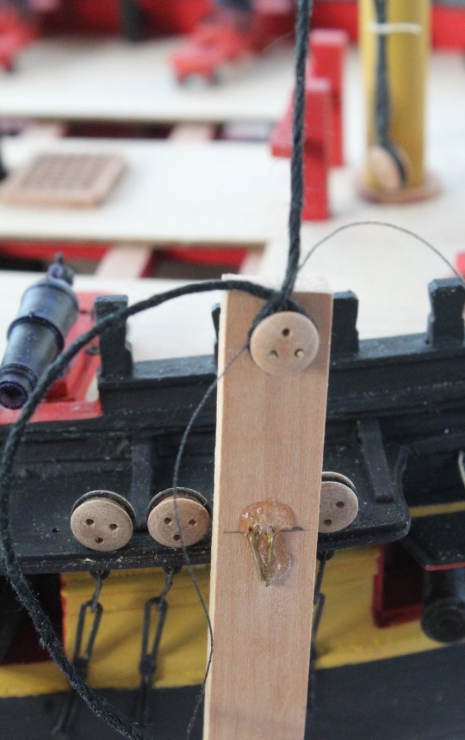
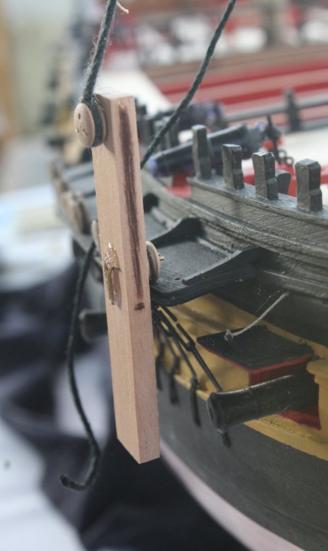
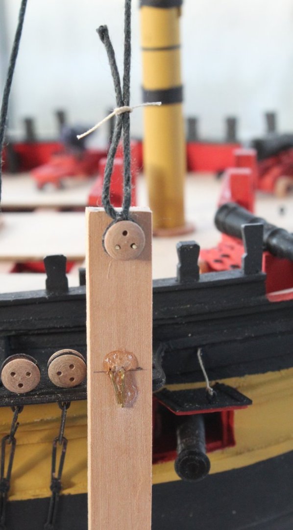
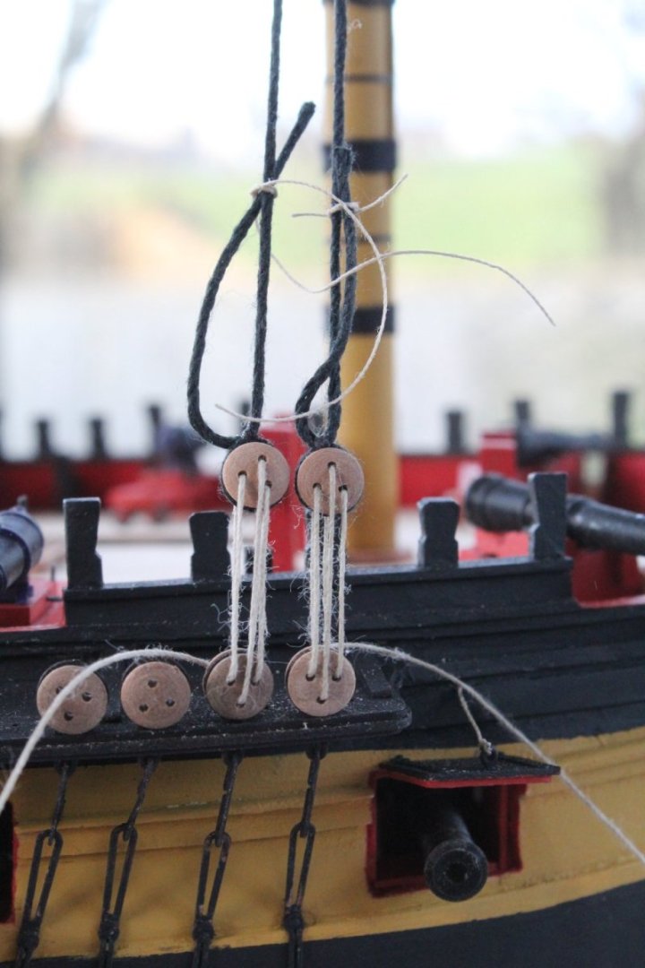
 Starting work on the fore shrouds After due consideration I decided to start with rigging the lower fore shrouds. Based on a bit of research I thought a spacing of 25mm would be an acceptable distance between the deadeyes. As a rule of thumb it seems this distance is normally 3 to 5 times the diameter of the deadeye. I made a simple jig to set the required distance between the deadeyes. With the jig in place a shroud line is wrapped around the deadeye. The loop was then seized. With the seizing completed the deadeye was correctly positioned in the shroud loop and the loop was tightened around the deadeye, using the jig to double check the spacing was correct. The following is another photo showing the jig in position. With the loop in place I added a temporary thread to hold the shroud end in place. These will be properly seized once all the shrouds have been added as I have a plan to ensure all the seizing's are level with each other. With the first shroud pair in place I added the lanyards, noting these will be redone as I plan to get rid of the fluffy edges. Once the lanyards were properly adjusted the phrase "Houston we have a problem" seemed appropriate. Thankfully It is not a major issue as I can easily redo the right-hand shroud, as the left-hand side lanyard spacing is set to the required distance.


-
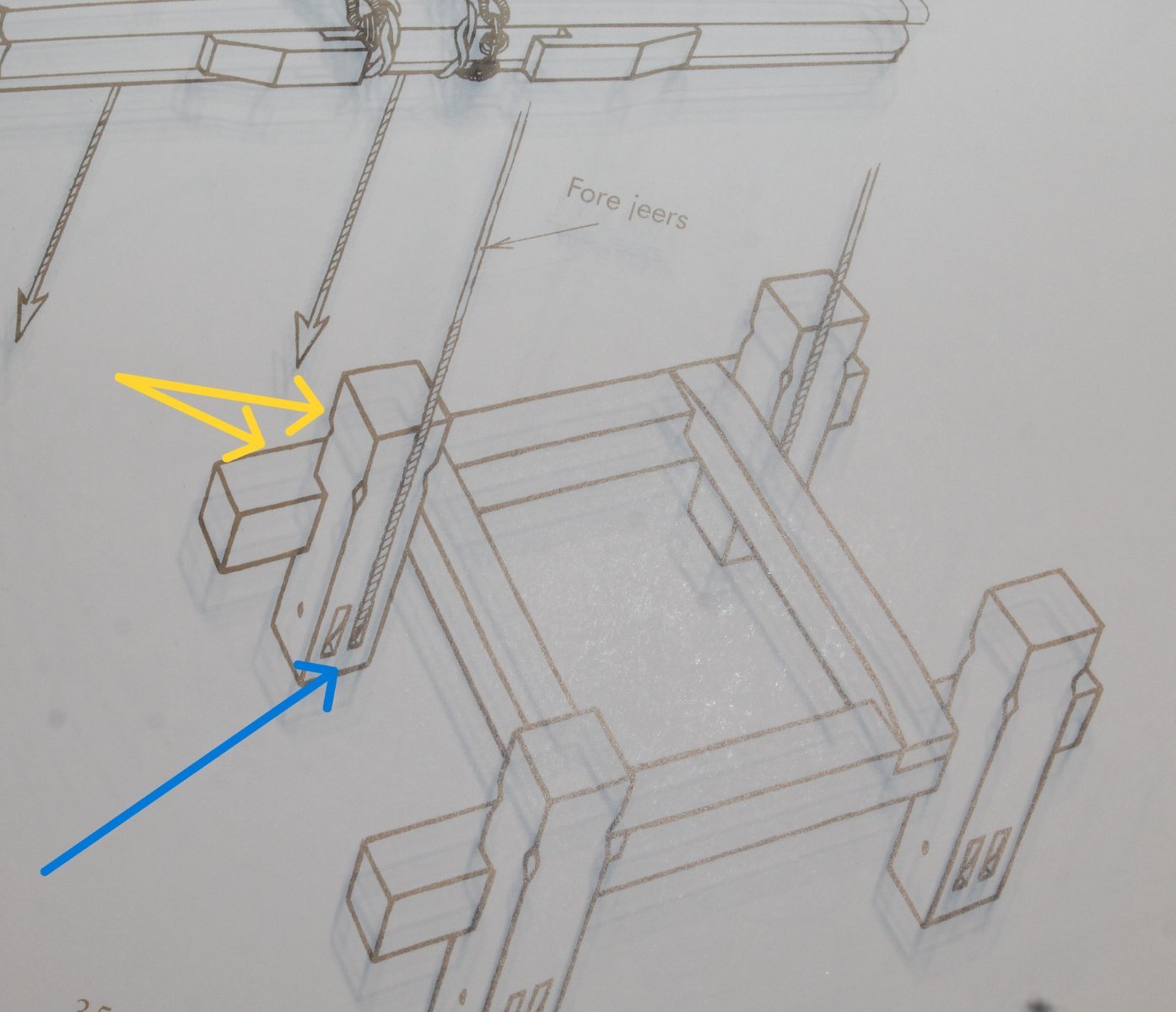
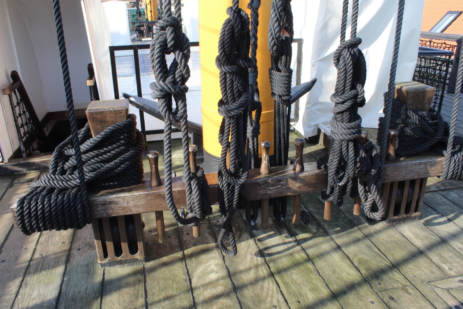
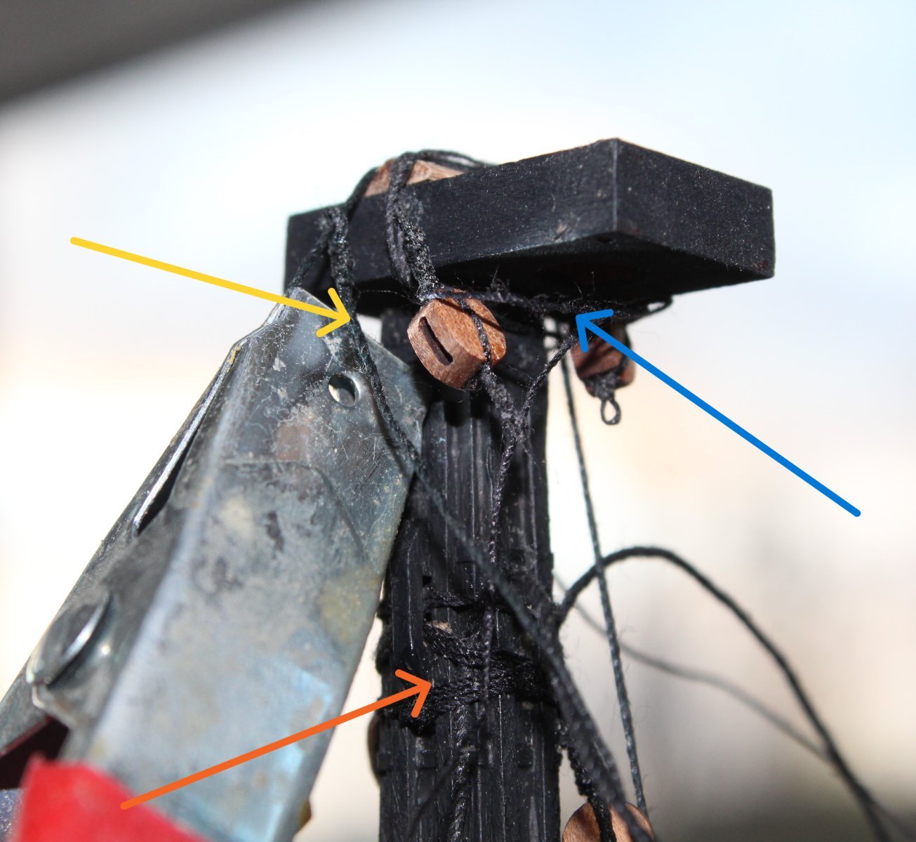
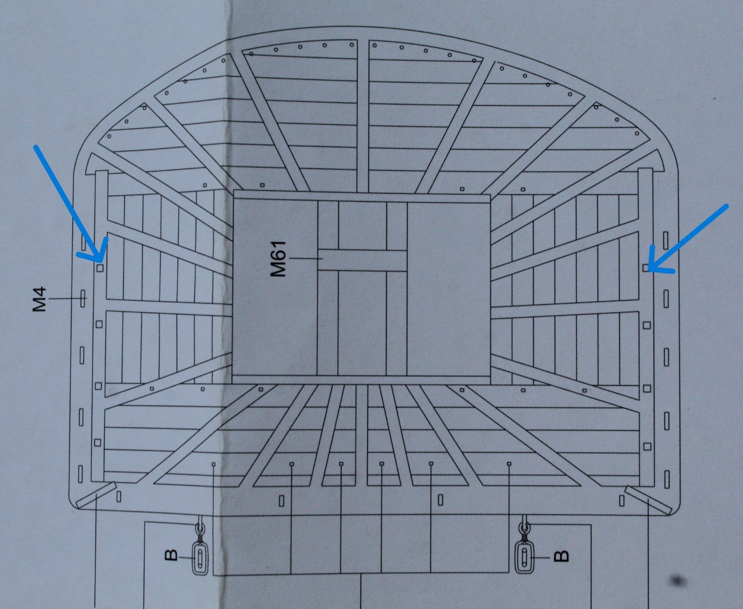
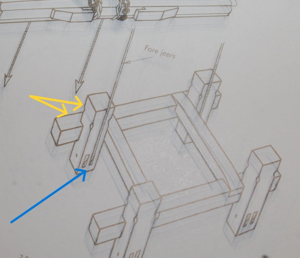
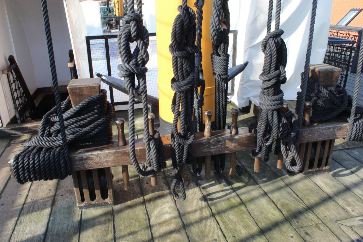
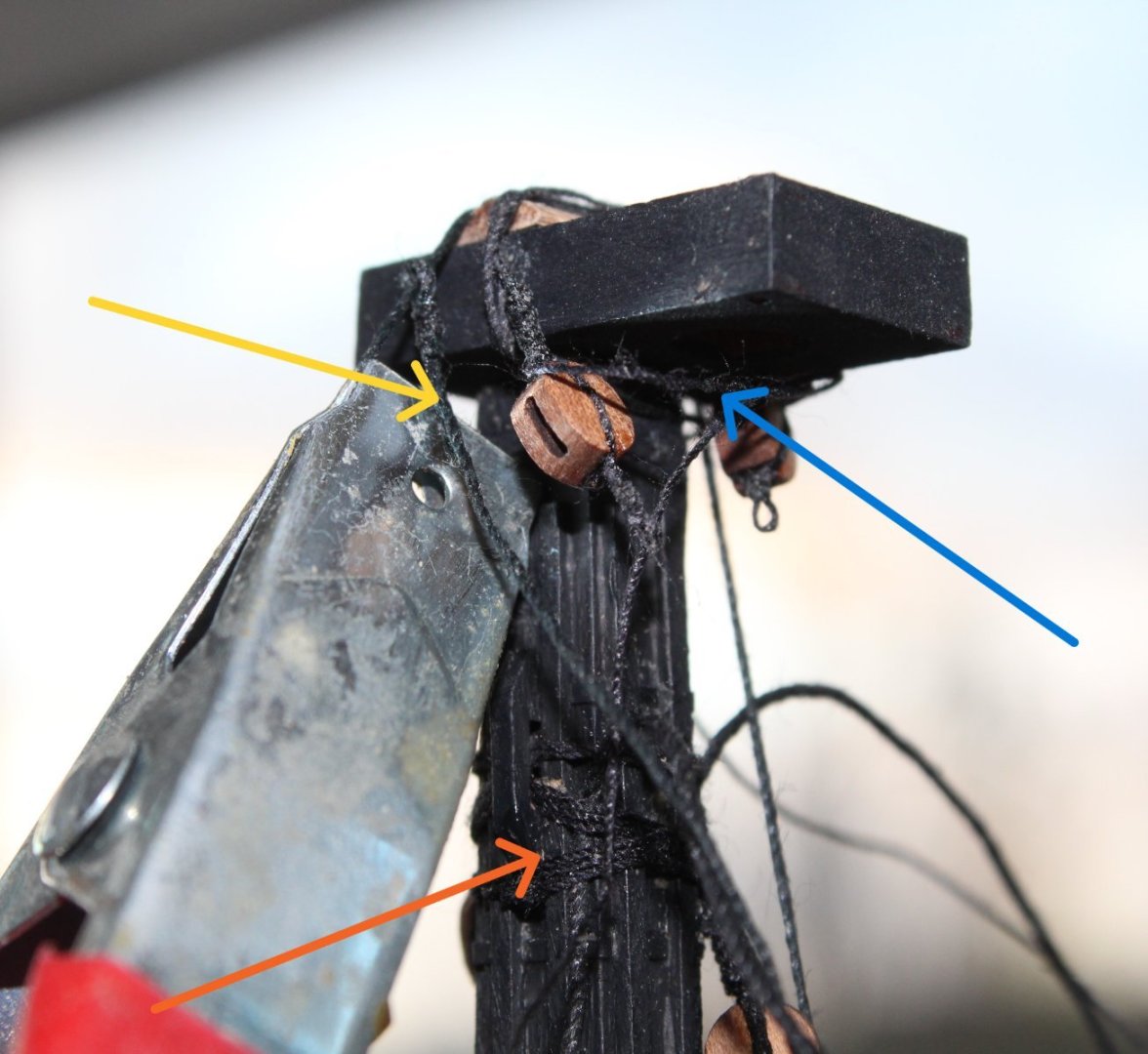
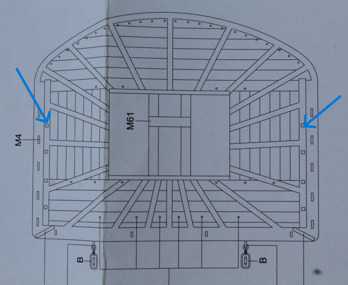
Many thanks for your advice @chris watton. I am currently tending toward adding the shrouds before the foreyard. The deck area, after looking at the belying requirements, seems to have a bit more room compared to the smaller models I've built. The one aspect I am not totally clear on is where the jeer line is belayed after it passed through the bitt hole (blue arrow). Either it should be wrapped around the bitt (top yellow arrow) or around the bitt rack (lower yellow arrow). The position of the belaying pins on the rack makes either option awkward. The photo I took last year (HMS Trincomalee) does not really help me.
-
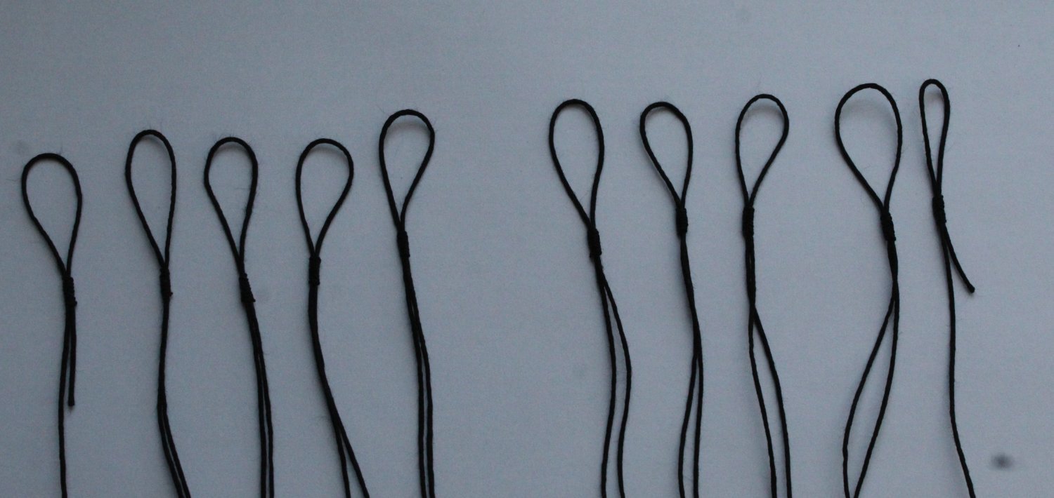
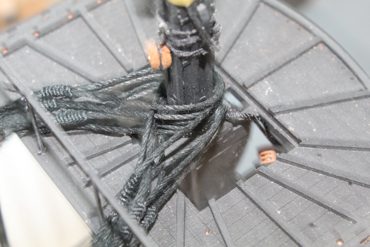
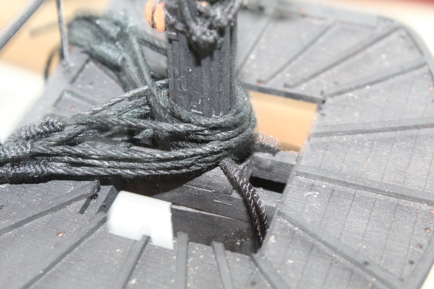
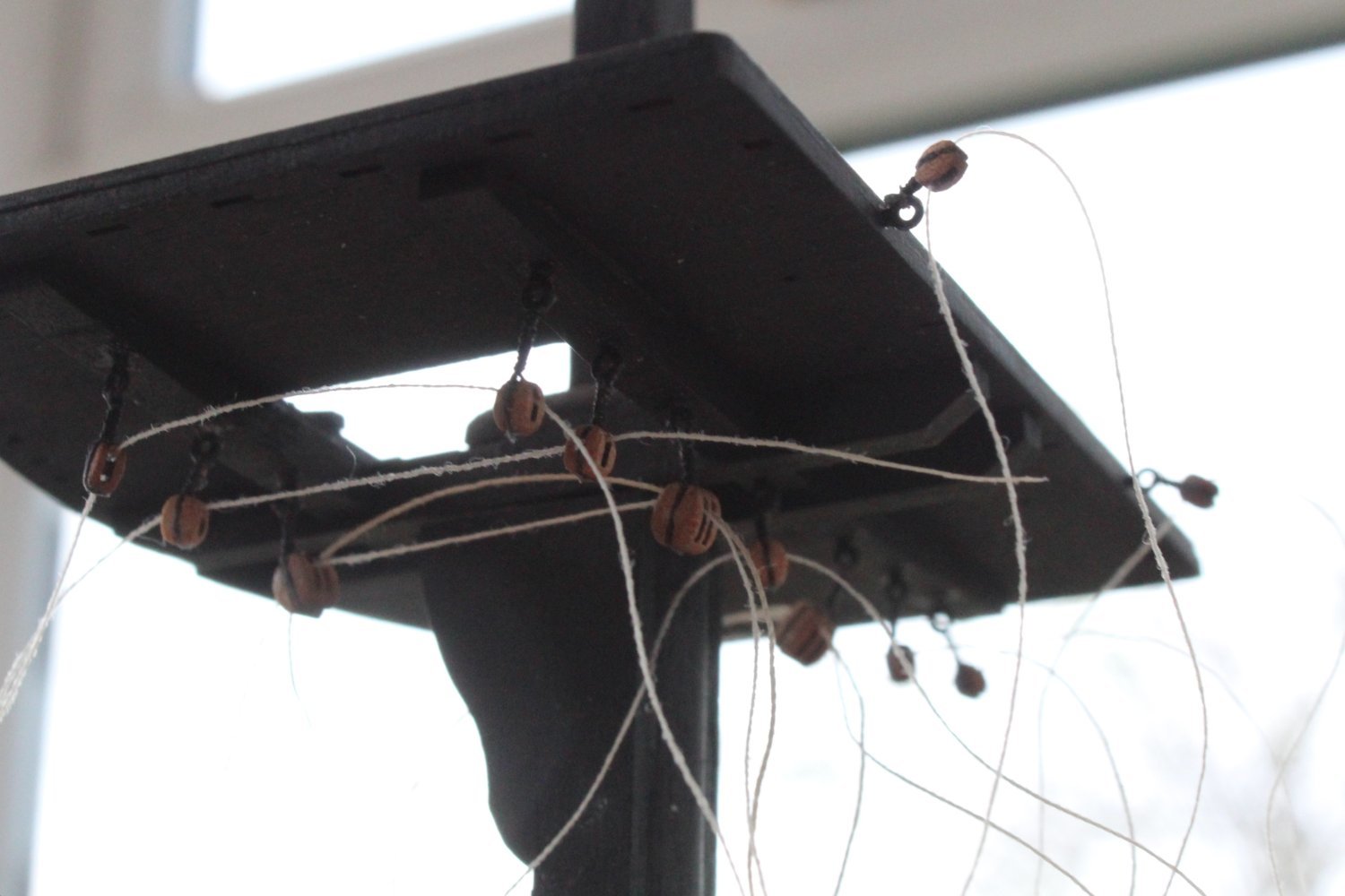
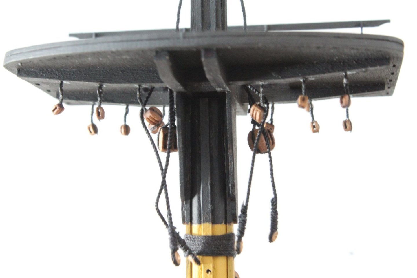
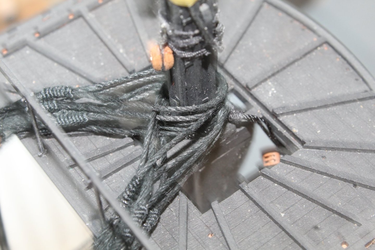
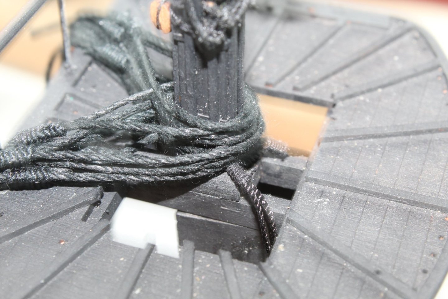
Decision Time My initial thought process was to add the foreyard to the foremast before the shrouds are rigged. The reasoning for this was for easy of access with regards to the foreyard central rigging (truss pendants, sling, jeers and lifts). With that in mind, after constructing the foremast, I built the foreyard which is now ready for installation. I am now reconsidering my strategy as this requires the end cap to be in place so the foreyard sling and lifts can be added and rigged. However I prefer to make the shrouds off boat and then drop them in place before the mast cap is added. This can be done as I can keep the shrouds out of the way whilst I add the foreyard and rig the truss pendants, sling, jeers and lifts. My concern is will the foreyard make adding the ratlines, futtock shrouds and catharpins more difficult. I decided that I should set the two jeer blocks located on the foremast to the required height and then seized to the figure of 8 lashing. With this done I then decided I should also add the burton pendants. I then decided that I should made the shrouds. The large loops allows the shrouds to be dropped oved the foremast. When the shrouds are correctly positioned the loop seizing can be adjusted to tighten the loop. The shrouds were then added to the foreyard, but kept them out of the way as can be seen in the photos below. Please note the shroud loops have not been tightened as the shrouds are not in their required positions. I am now going to study the rigging plans (again) to see where the truss pendants, jeers and lifts are belayed at deck level before deciding on weather to rig the shrouds or to add the foreyard next.


-
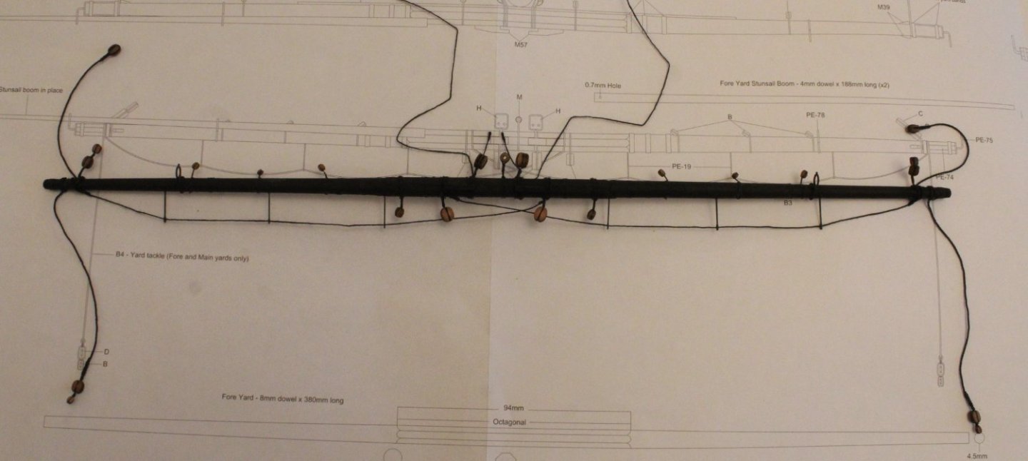
Foreyard It took quite a bit of time to add the various blocks to the foreyard. It is important to ensure the block holes are correctly positioned and orientated on the foreyard, in readiness for the rigging stage later on in the build process, as they are added. After the all the blocks had been secured to the foreyard I turned my attention to the truss pendant rigging. I started the process by creating a thimble to one end of each truss pendant. The truss pendants were then secured to the foreyard. The final task was to add the footropes. Thankfully this turned out to be a relatively straight forward task. I started by creating the loops either side of the foreyard mid point. The footropes were then passed through the footrope stirrups. I then made a loop each end which were placed over the end of the foreyard and positioned just before the end cleats. The two end loops were then slowly tighten up until I was happy with how they footropes looked. I have added a selection of photos of the completed foreyard. Before securing the foreyard to the foreyard I will add the lower fore shrouds to the foremast.

-
Seizing Blocks With Alternate Half Hitch Knots
Glenn-UK posted a topic in Masting, rigging and sails
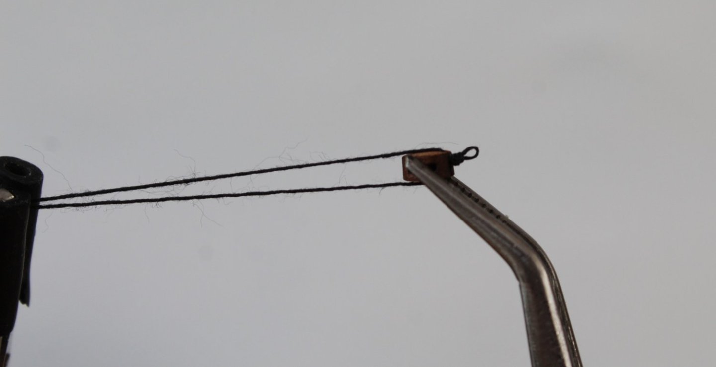
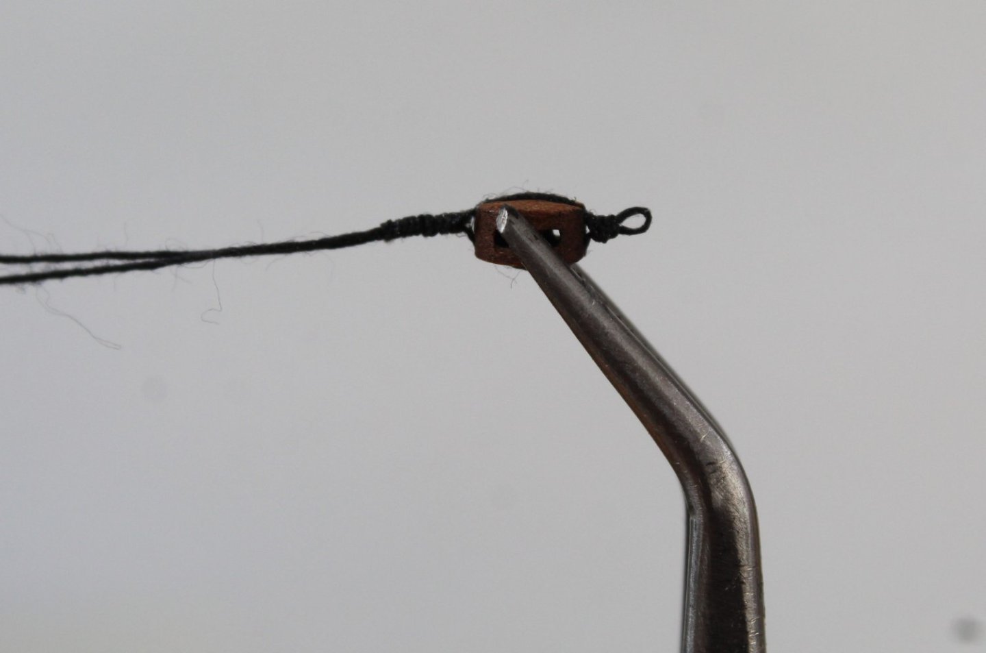
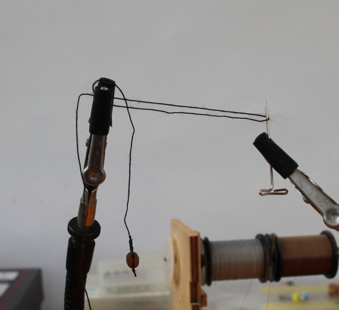
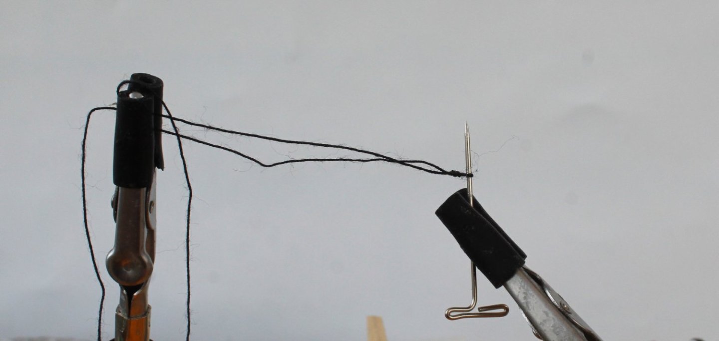
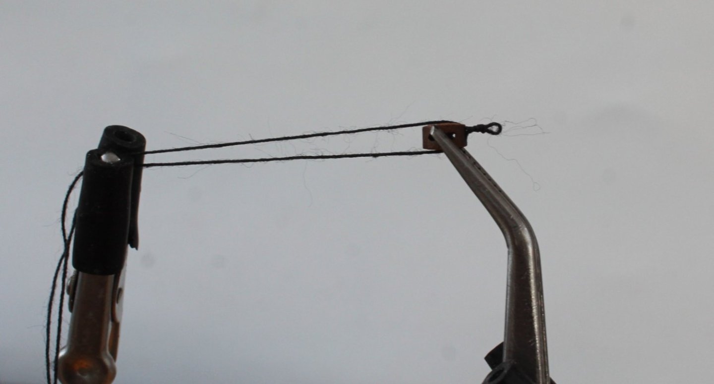
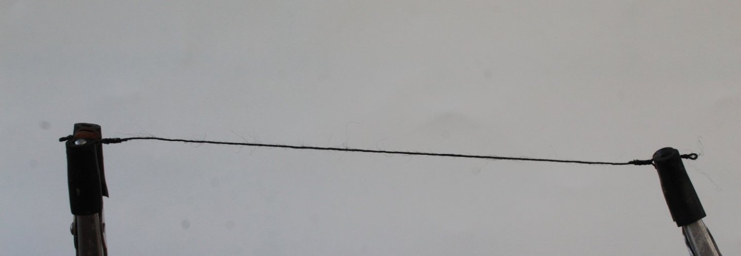
Seizing a Block I have often described in my build log posts the method I use to seize a block using a series of alternate half hitch knots. Today I thought I would make a video showing how I do this in real time. In this video a 4mm single block is wrapped with 0.25mm black thread and then seized with 0.1mm black thread. With the block held in place using my quadhands the video starts after a length of 0.25mm black thread had been wrapped around the block. Sometimes the seizing can slide away from the block during the seizing process therefore you will note after I added the first pair of half hitch knots a touch a ca glue was used to prevent the slide from happening. This video also shows that once I had completed the seizing a micro drill was used to check the block hole and the required rigging line was then test threaded. This method works really well for me, but I know modellers will have other methods which suits them better,- 1 reply
-
- 13
-

-

-
Seizing a Block I have often described in my build log posts the method I use to seize a block using a series of alternate half hitch knots. Today I thought I would make a video showing how I do this in real time. In this video a 4mm single block is wrapped with 0.25mm black thread and then seized with 0.1mm black thread. With the block held in place using my quadhands the video starts after a length of 0.25mm black thread had been wrapped around the block. Sometimes the seizing can slide away from the block during the seizing process therefore you will note after I added the first pair of half hitch knots a touch a ca glue was used to prevent the slide from happening. This video also shows that once I had completed the seizing a micro drill was used to check the block hole and the required rigging line was then test threaded.
-
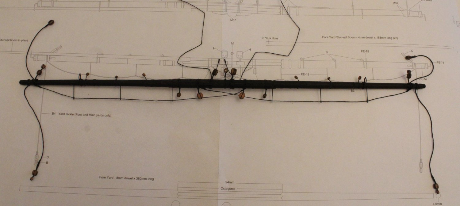
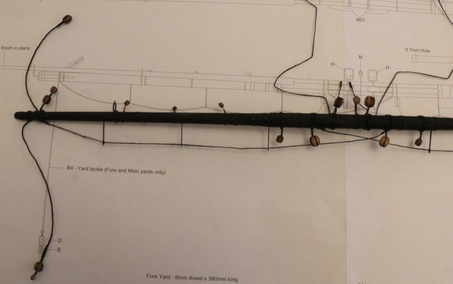
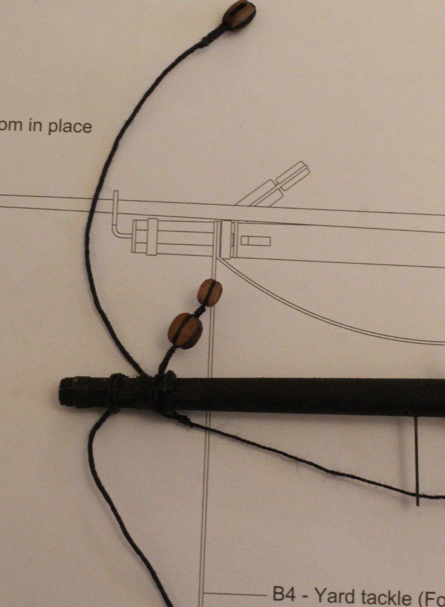
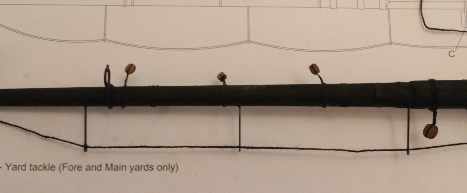
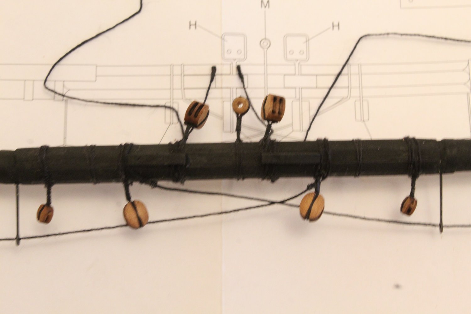
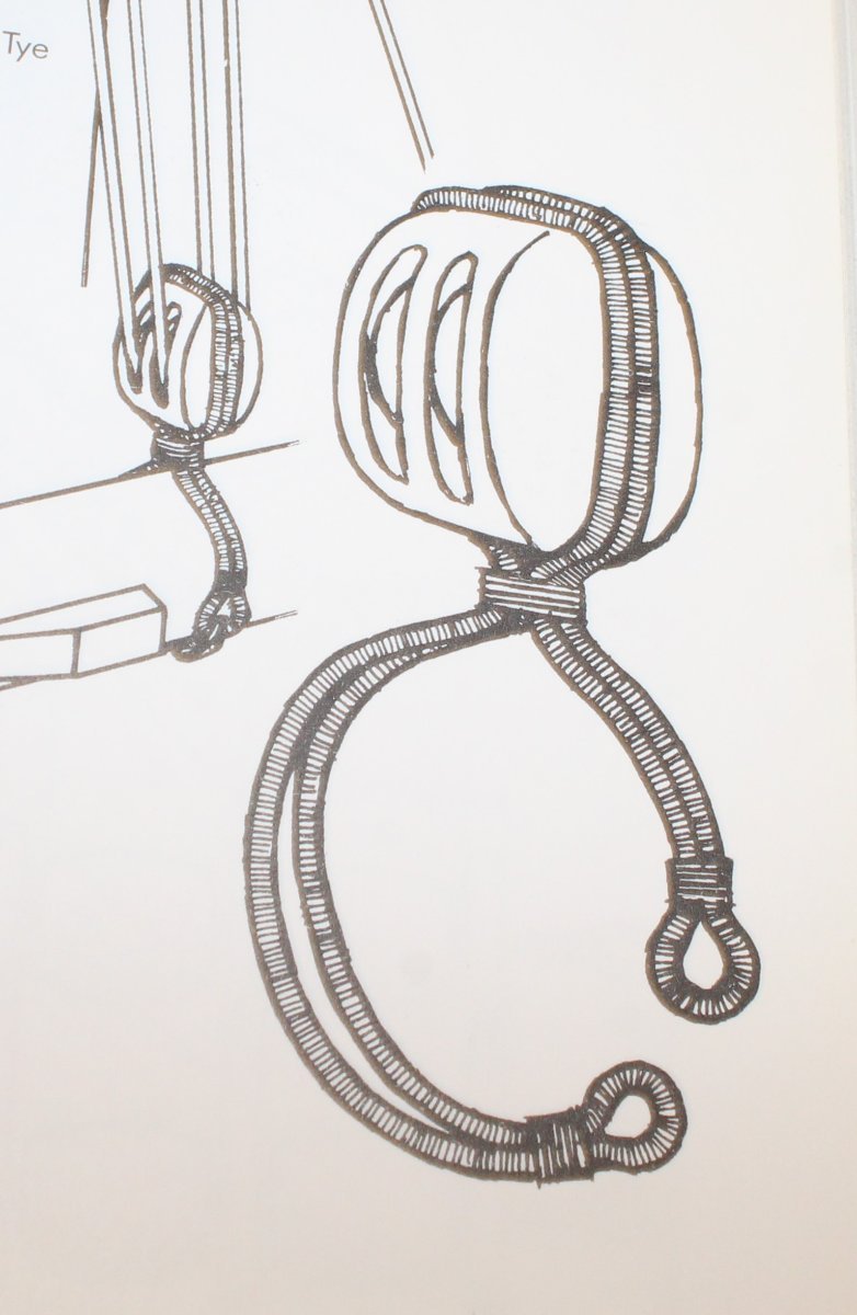
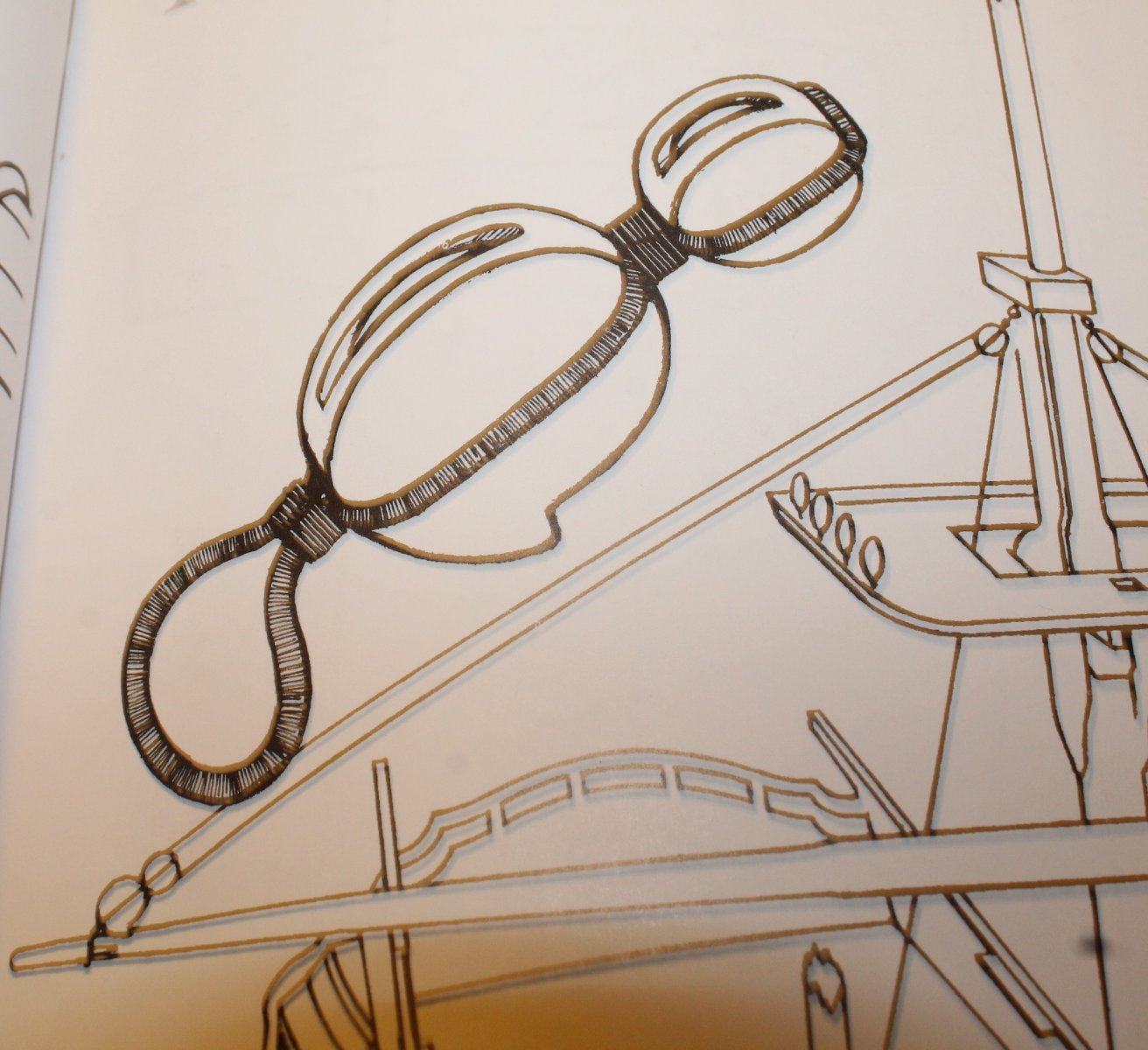
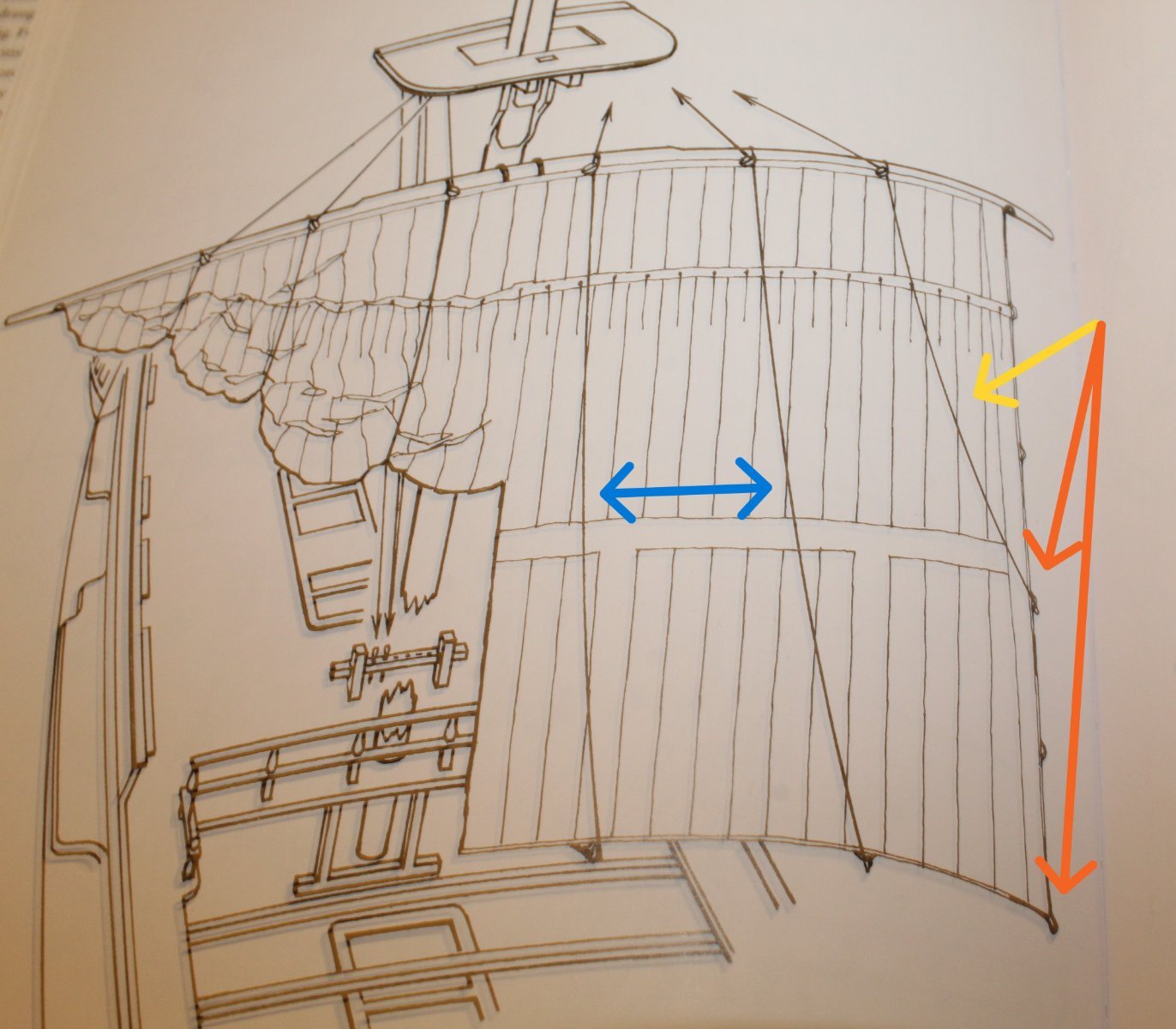
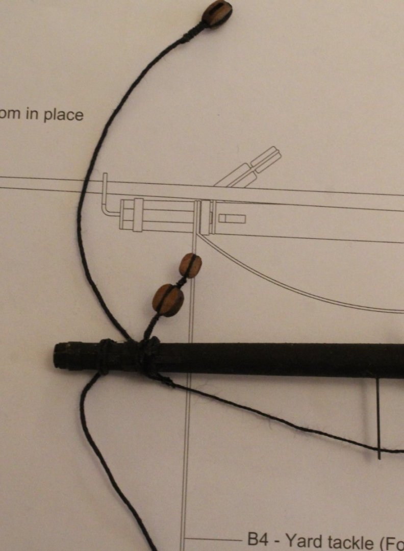
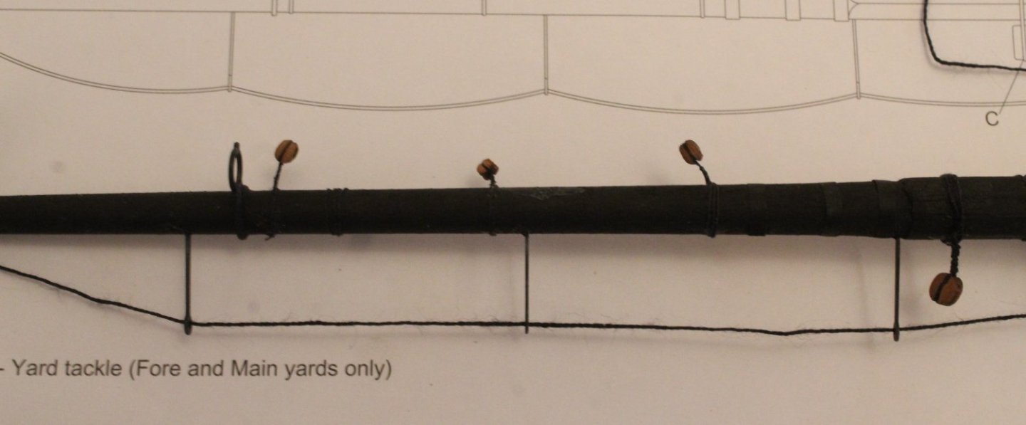
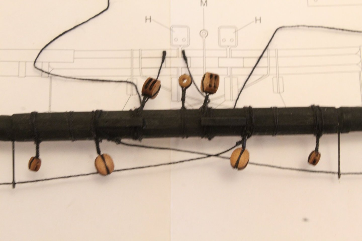
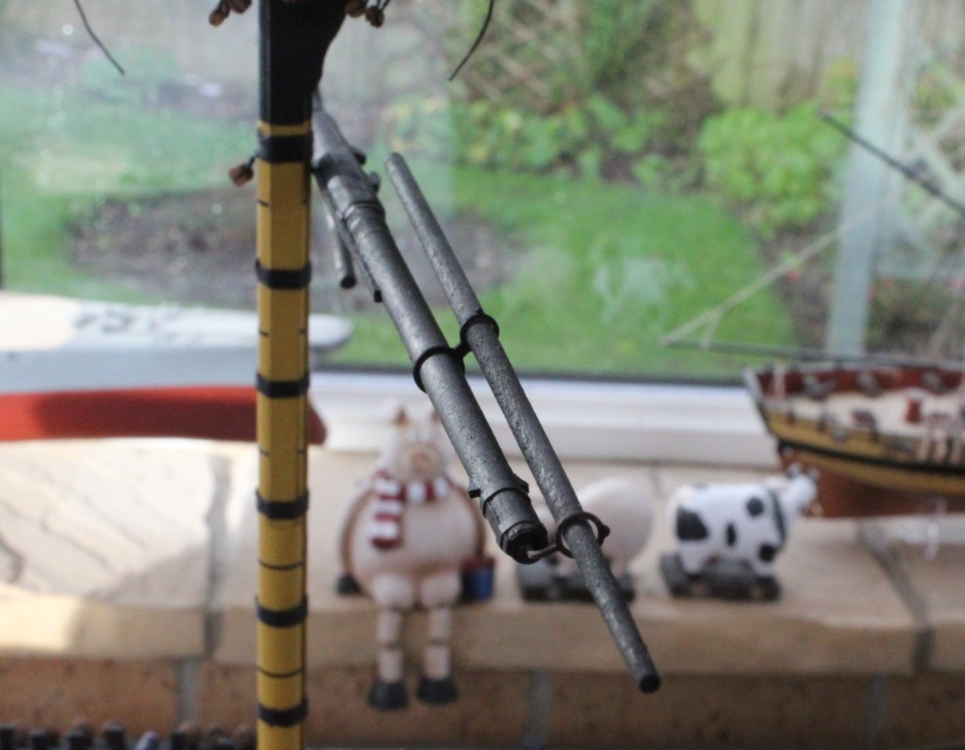
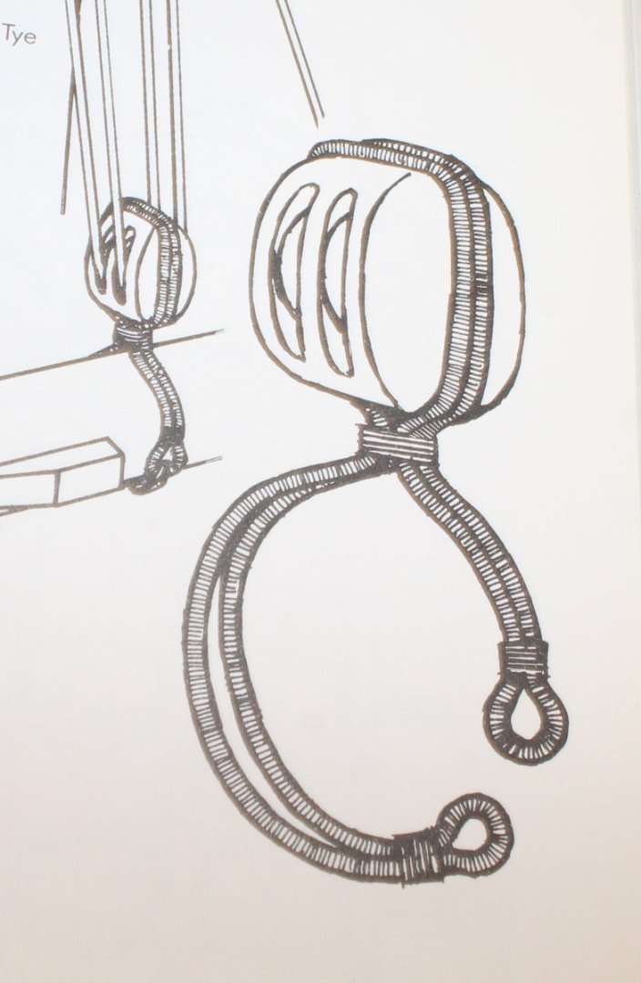
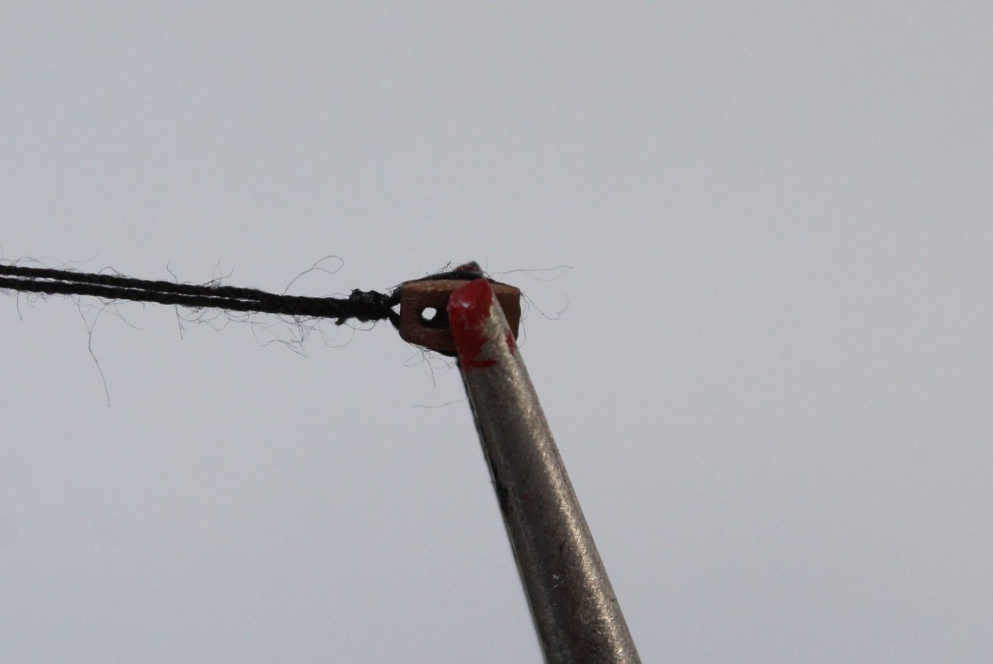
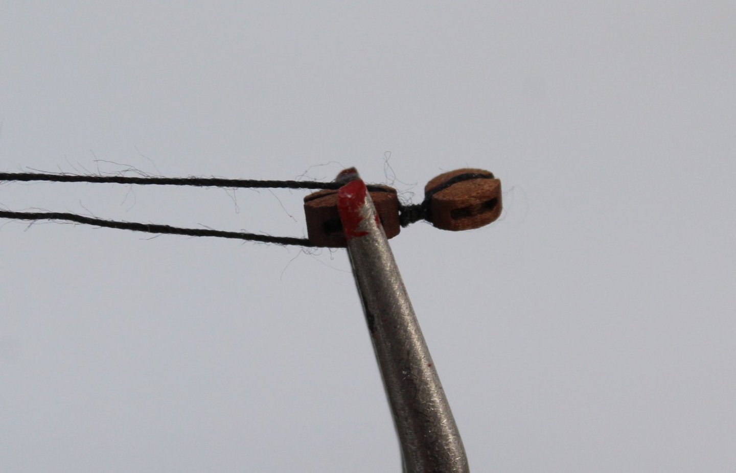
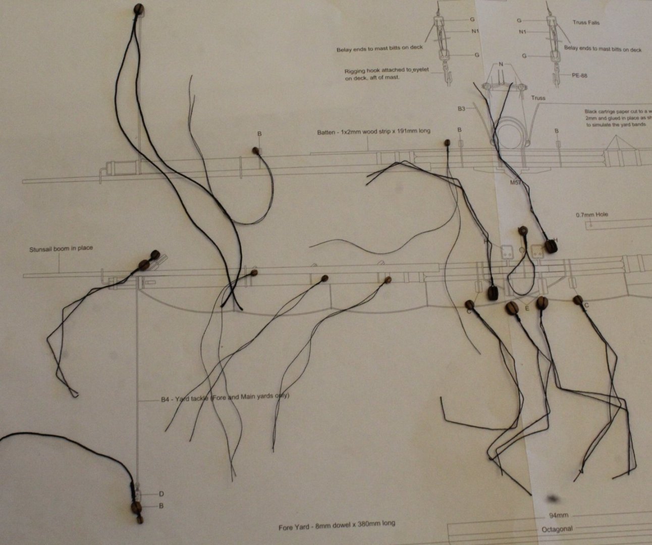
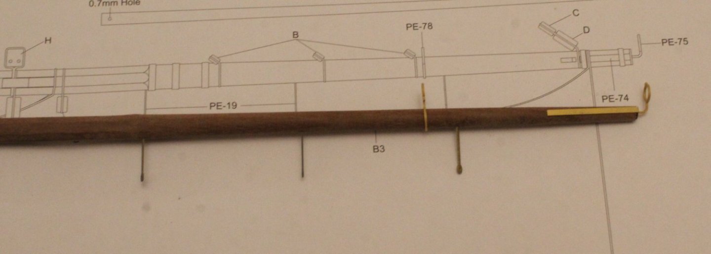
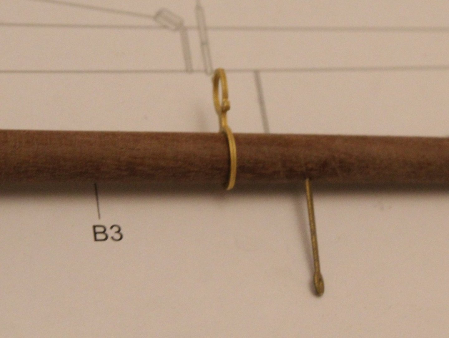
Foreyard Stunsail Boom I had been pondering where to fit the stunsail boom in relation to the foreyard. I had an inking should not be positioned directly above the foreyard but was not 100% sure. With many thanks to @allanyed who confirmed that the stunsail boom should be rotated forward by approx 45 degrees for ships built after 1773. I used Allan's information to set the position of the yard irons, as can be seen below. Block Fitted to Foreyard Before moving on to adding the various blocks to the foreyard I decided to do a bit of research to try to understand their purposes and to check the required rigging lines from Chris’s excellent rigging plans. There are quite a few blocks to seize and fit, as detailed in the ensuing text. Sling Thimble A loop is wrapped around the central point of the foreyard with a thimble positioned on top. This is used to hold the foreyard in place once it has been hoisted into position using the jeer block and tackle. This thimble is linked to a second thimble which is wrapped around the foremast end cap. To create the sling a length of 0.25mm black thread was double wrapped around the thimble and seized (10 upper and lower half hitch knots) with 0.1mm black thread. The excess thread ends were trimmed to leave the required sling which is ready to be secured to the foreyard. Jeers Two double blocks are located on the foreyard, each situated either side of the foremast. These will be linked to triple blocks which are wrapped around the mast (above the platform) and hang down below the platform. These blocks are used to hoist the foreyard into position. A length of 0.25mm black thread was wrapped around each jeer block and was seized with 0.1mm black thread. According to Longridge’s book, reference Plan No.8 (page 213) two loops are added to each jeer block which are then tied together to secure these blocks to the foreyard. I will secure the jeer blocks to the yard either using a simple clove hitch knot or a reef (square) knot. Fore Topsail Sheet and Yard Lifts Blocks and tackles are used to hoist the sail up from the deck using the clewlines which are attached to the outer corners (clews) of the sail. Once the sails have been hoisted up from the deck they can be tied to the yards. A double block arrangement is fitted to each end of the foreyard. The inner larger block is used for the topsail yard clewlines and the outer block is used for the yard lifts. Clewlines, taken from the fore topsail yard, are fed through the inner end blocks, and are then fed from through additional blocks on the foreyard situated beneath the jeer blocks and are then belayed to the bitts. Yard lifts are used to adjust the foreyard position in the vertical axis, in conjunction with blocks fitted around the mast cap. The outer blocks are used for the yard lifts. To create the double block arrangement a length of 0.25mm black thread is wrapped around the outer smaller block and seized with 0.1mm black thread (4 lower and 4 upper half hitch knots). The two free ends are then wrapped around the second larger block and seized with 0.1mm black thread (10 lower and 10 upper half hitch knots). The correct method for securing these double blocks to the foreyard should be via linked loops (as per the jeer blocks) but I will use a simple clove hitch or reef knot. Seizing the outer block. The second block held in position, using my guadhands, as is ready be seized. The completed double block arrangement. Foreyard Tackle The yard tackles are used to allow the yards to be used as cranes. They can be stowed, when not in use and they hang down from the foreyard when in use. They are located at either end of the foreyard and each tackle comprises a double block arrangement. Chris’s plan sheets shows both rigging options so it will be left to the builder to configure either way. The double block will be created as per the topsail / yard lift double blocks with the addition of a thimble. These will be attached to the foreyard with a flying lead with either clove hitch or reef knots. The flying leads will be secured to the blocks via the thimble. This is a photo of how the double block should look which I did replicate. The block arrangement, complete with the flying lead seized. Foreyard Braces The braces operate as a pair of lines used to rotate the foreyard around the mast, either to port or starboard, to allow the ship to sail at different angles to the wind. They are located at each end of a foreyard. Once seized the blocks will be secured to the foreyard via clove hitch or reef knots. Bunt and Leech Blocks There are two blocks per side for the bunt lines. There is one block side for the leech lines. The bunt and leech lines are used to lift the middle and outer edge sections from the deck. These are simple blocks to seize and will be secured to the foreyard with clove hitch or reef knots. Each block will be wrapped with 0.1mm black thread and seized using black fly tying thread. In the photo below the blue arrow shows the bunt lines and the yellow arrow indicated the leech line, which could be secured to the mid point or bottom corner (orange arrows). Fore Sail Tack The clue line starts on the foreyard and is taken down to the fore sail tack block arrangement and then feeds through the clew line blocks located on the foreyard before being taken down to the deck level. The clew line blocks will be wrapped with 0.25mm black thread and seized with 0.1mm black thread and then secured to the foreyard with clove hitch or reef knots. Blocks ready to be added After a fun day seizing all the blocks are now ready to be added to the foreyard. I have stopped work for the day as the light is starting to fade.


-
They are tricky cleats to fit, you've done well to get them all in place.
- 233 replies
-
- 1
-
-
- Indefatigable
- Vanguard Models
- (and 1 more)
-
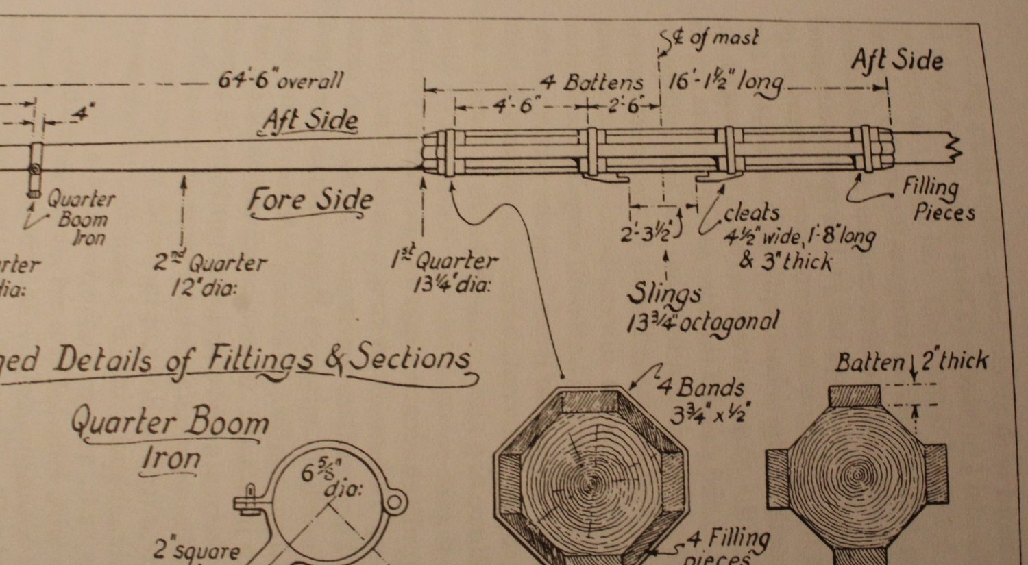
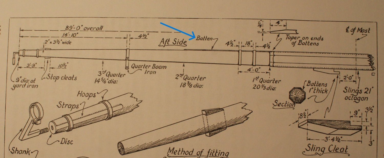
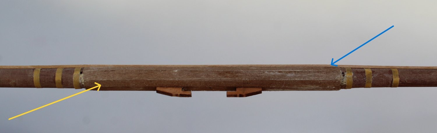
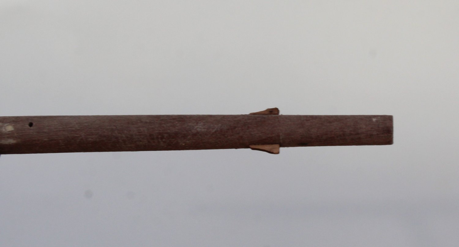
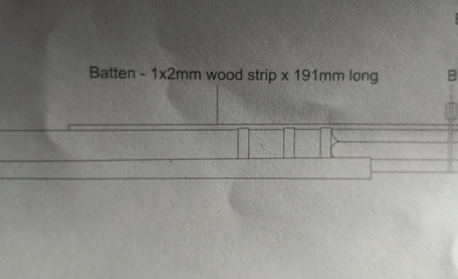
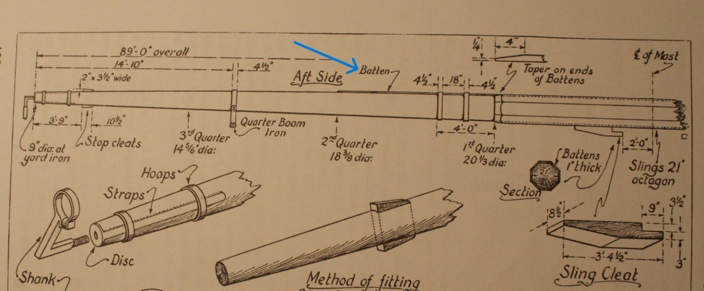
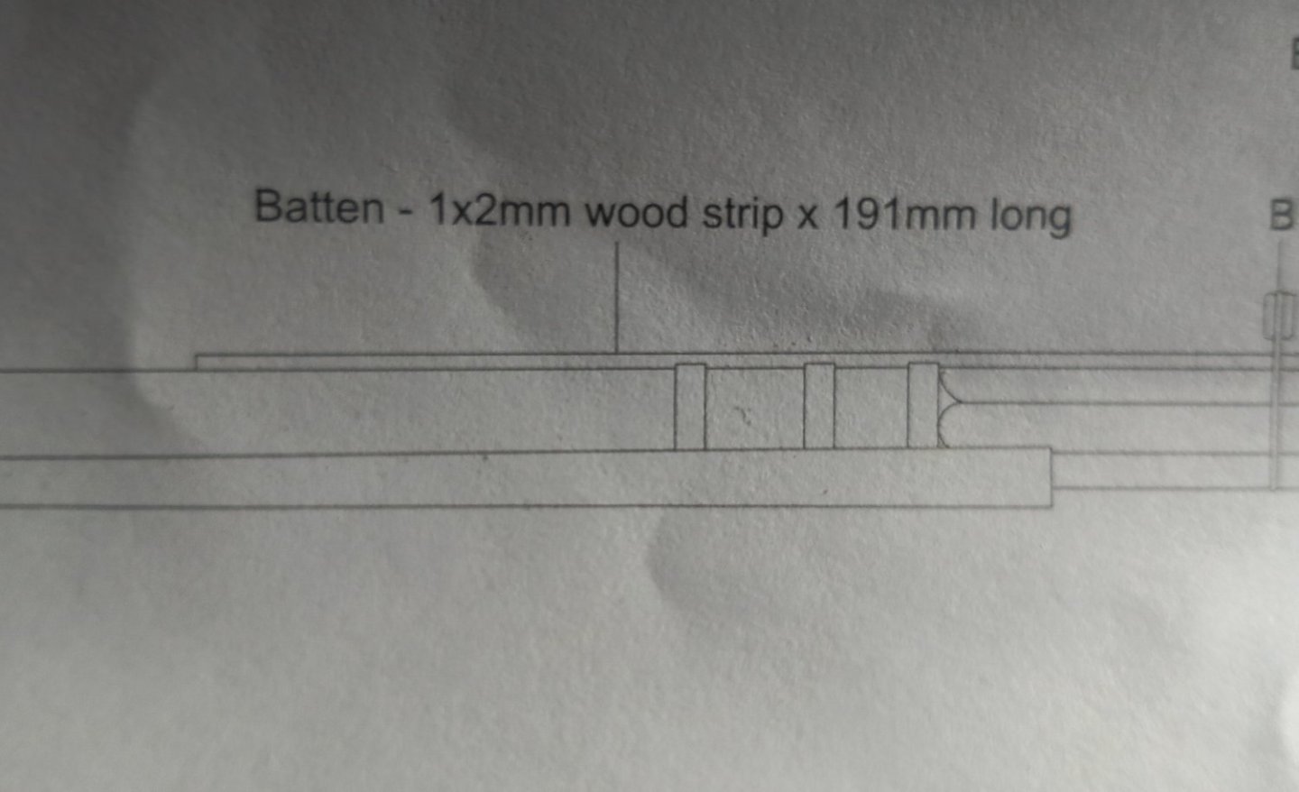
Foremast Work Slow Progress Due to more grandparent duties work on completing the foreyard has been very slow this week. After making the basic foreyard from the 8mm dowel, as detailed in my last post, I looked in Longridge's book. I noted that it is common to add an outer set of batten's to the octagonal central section. This is something I feel is worth adding. I had noted an additional batten is fitted along one edge, as shown in Longridge's book and this is also shown on Chris's plan sheet. I did have some suitable 3mm wide x 0.5mm thick planks which I was able to use to add the required battens to the central octagonal section (yellow arrow). It is not clear in the following photo but I did taper the octagonal batten ends, as shown in the Longridge picture. I used some 2mmW tape to simulate the iron banding, which will look OK when painted black. The two central cleats and 2mm batten (blue arrow) were then added. The foreyard is now ready to be painted black. I did make a school boy error by adding the 4 off end cleats. With these cleats in place it will be impossible to fit the inner stunsail boom irons. I will have to remove them carefully and refit them at a later stage.


-
The lathe is a great addition to have for making the yards.
-
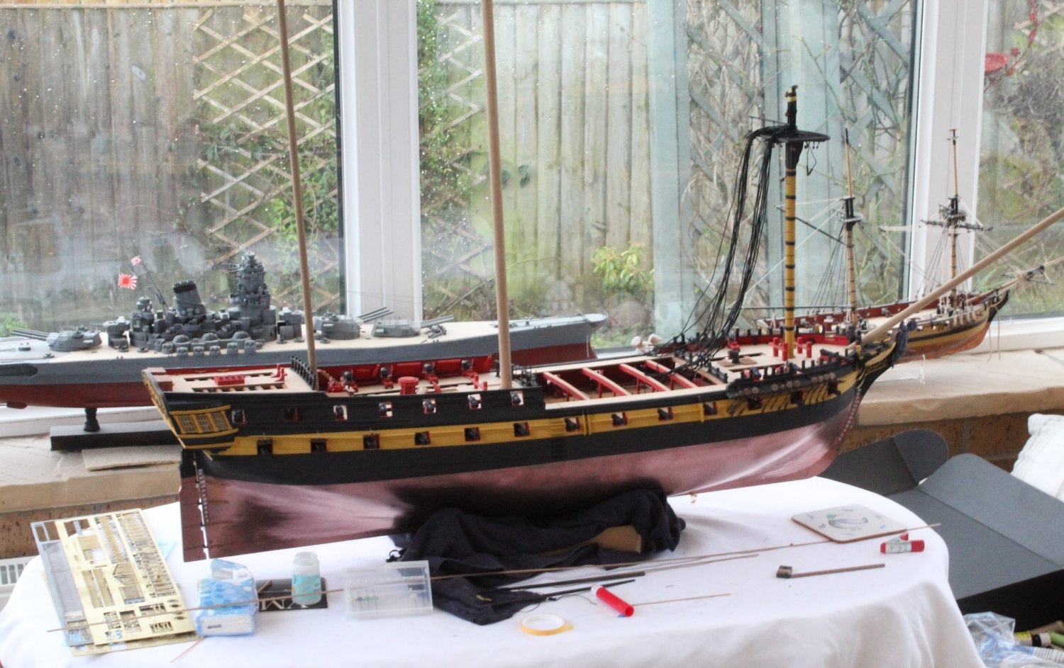
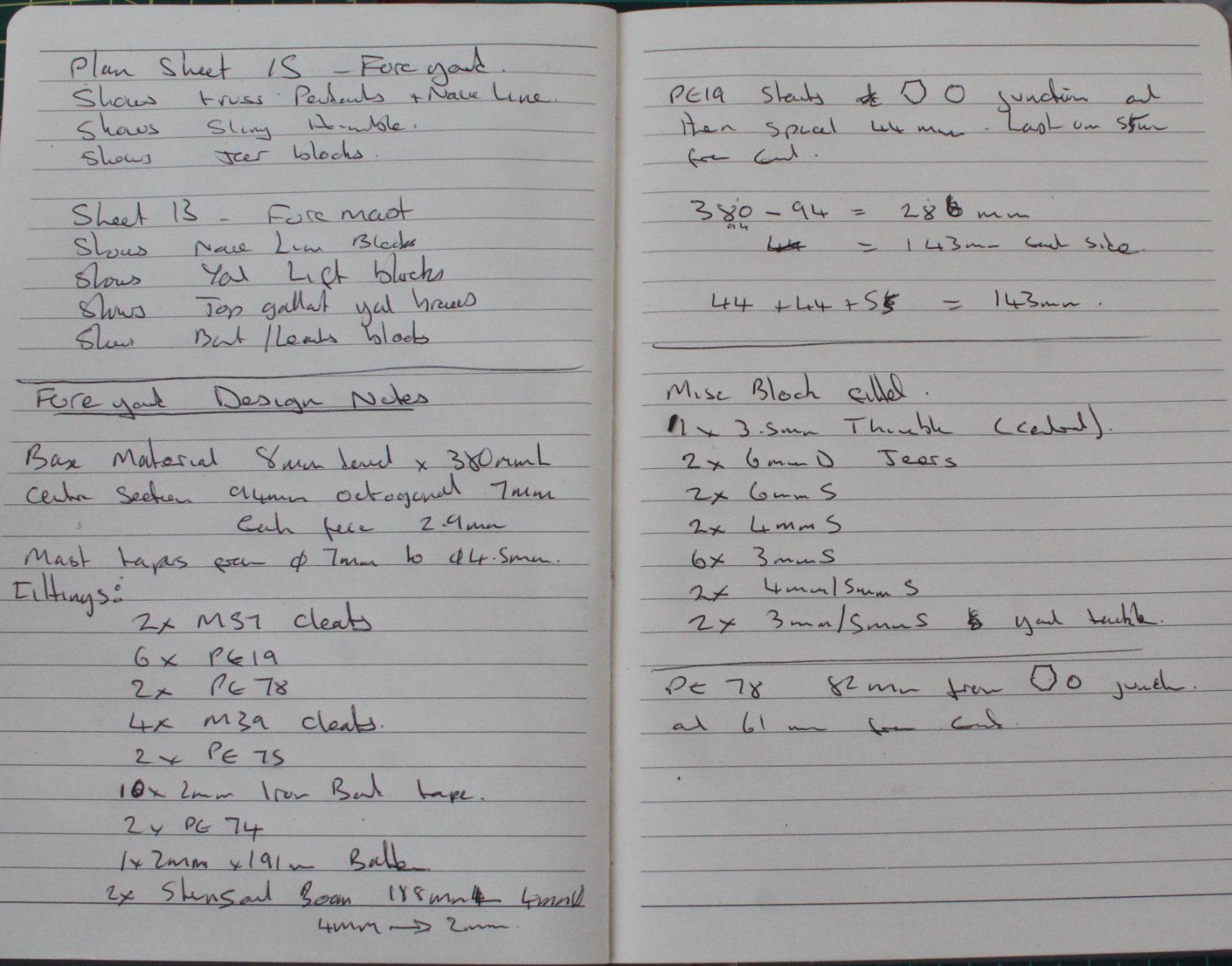
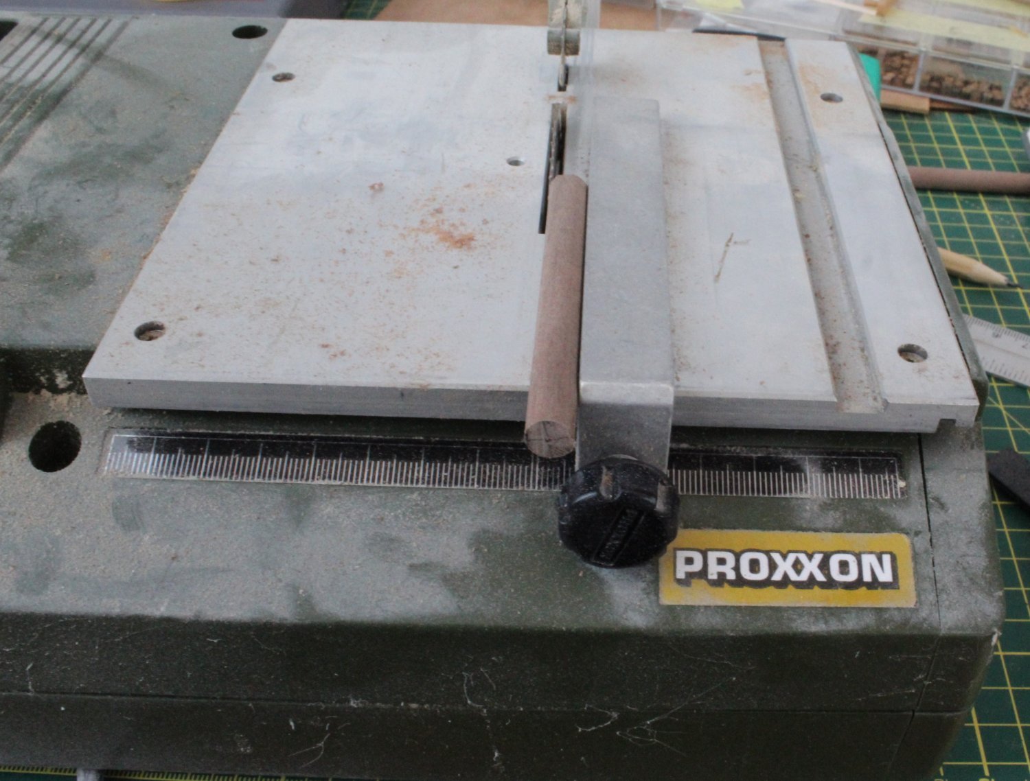
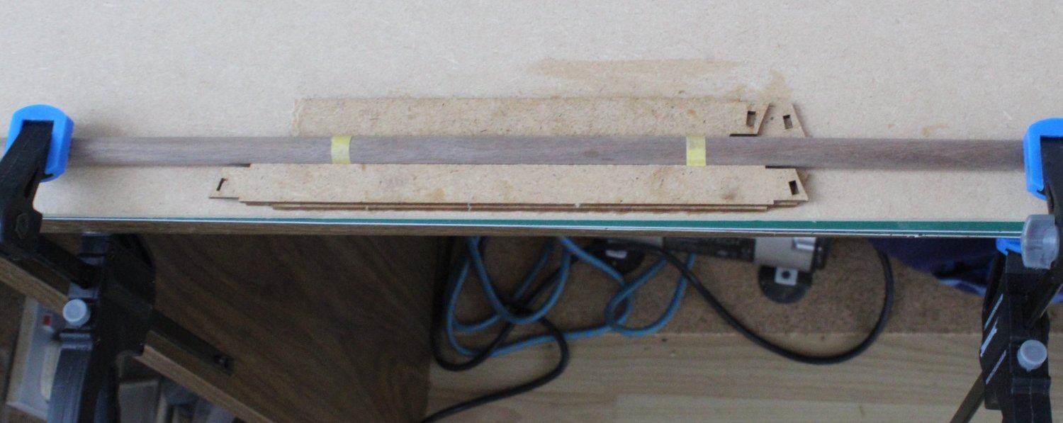
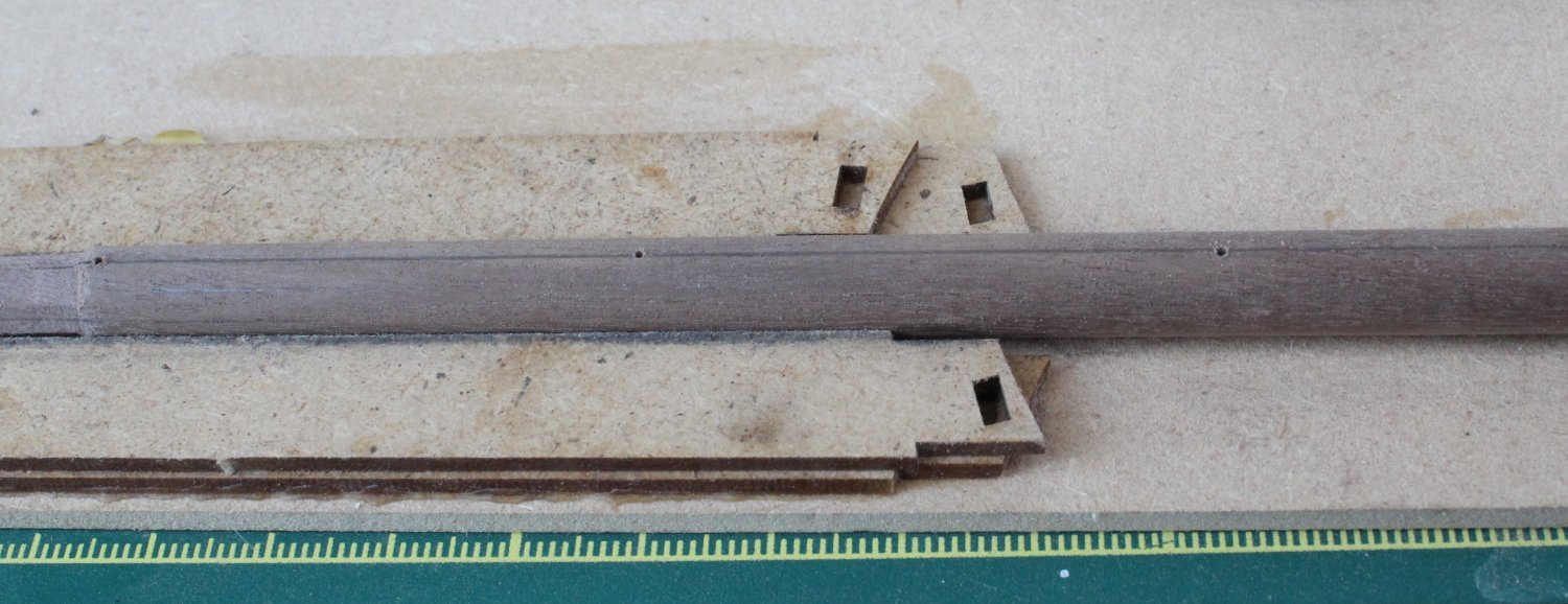
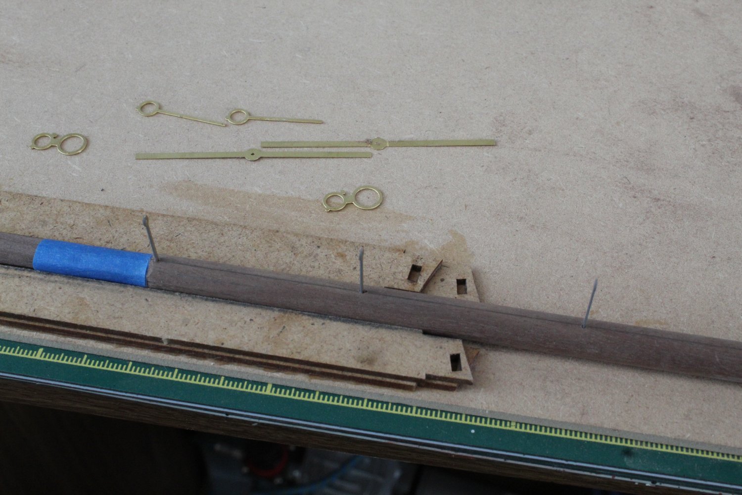
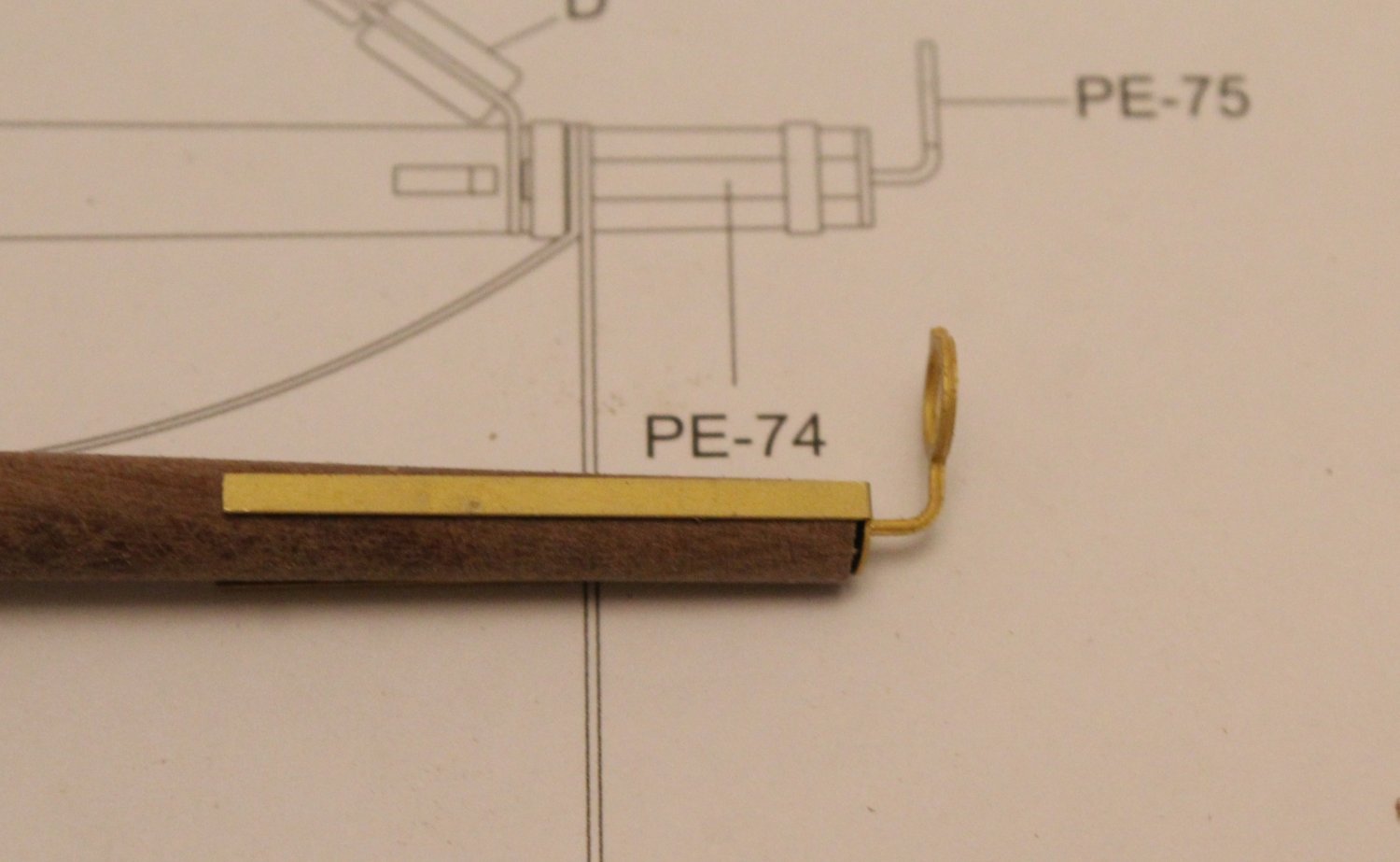
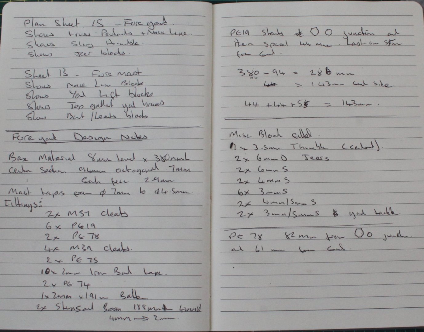
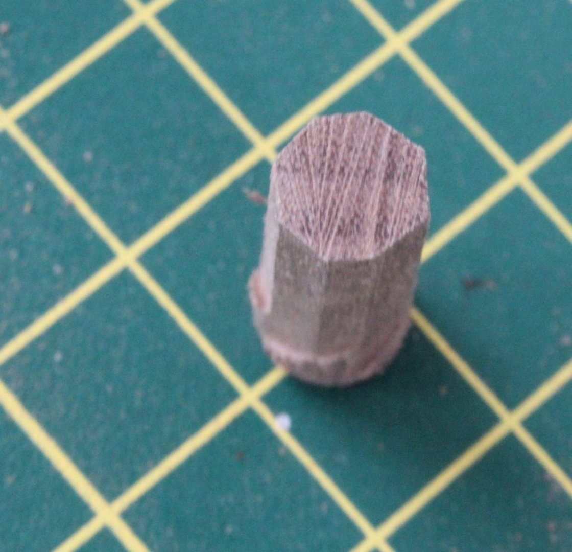
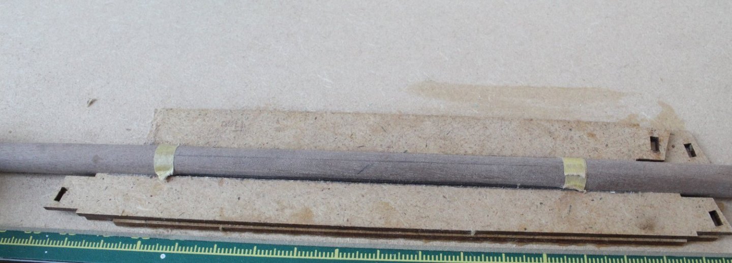
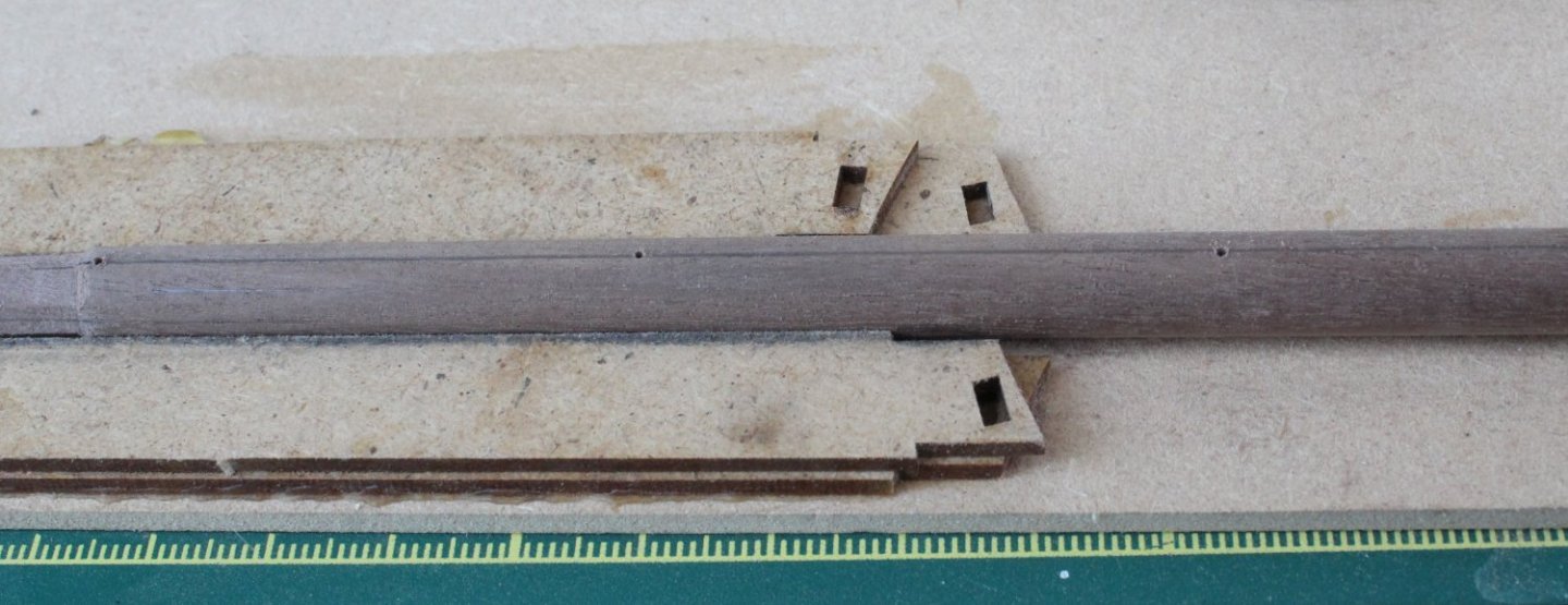
Thoughts and Start of Making The Lower Foreyard Today I started work on making the lower foreyard. The foreyard is 380mm long and is manufactured from a length of 8mm diameter dowel. The central section is octagonal (7mmW) and either side is circular tapering from diameter 7mm down to 4.5mm. There are a few PE parts, cleats and blocks to add to the foreyard, once the foreyard has been made. After looking over the plan sheet I made a few notes for easy reference. I have been considering different options with regards to making the central octagonal section. My first thought was to use a length of square material which will assist greatly with making a nice looking octagonal section. I could then round off and taper either end in my proxxon lathe. I decided to put this method on the back burner for the time being. I also tested a method of making the required shape using my table circular saw. As can be seen in the next two photo's it did work to a degree. However when I tried the same method on a longer piece of dowel I realised this method was not going to be that successful. I decided it might be easier if I could make a simple jig. I added two 4mm high parts to a base plate. These were parts were positioned so the dowel was a snug fit and clamps can be used to stop any unwanted movement. I then used a needle file and a sanding block to add the flat edges. With the brackets being 4mmH meant I could draw lines along the midpoint of the dowel. I start the shaping process by making a 7mm x 7mm square shape. The drawn lines ensures it is easy to accurately rotate the dowel through 90 degrees. It is also easy to add a line so the holes can be drilled for the yard footrope stirrup. I find it easier and more accurate to add these holes prior to tapering the dowel. Once the octangle shaping was complete I added the first taper, using my proxoon lathe. I started by reducing the overall diameter from 8mm down to 7mm along the whole length. I then created the required taper checking the diameters for both the inner lower stunsail boom iron and lower stunsail boom end cap. As can be be seen in the final three photo's everything seems to be a good fit, noting they are only dry fitted. Inner Lower Stunsail Boom Iron and a Yard Footrope Stirrup Outer Lower Stunsail Boom Iron and Lower Stunsail Boom Iron Cap


-
Thanks, I think I need to remove and reshape it a bit to match the picture provided in Longridge's book
-
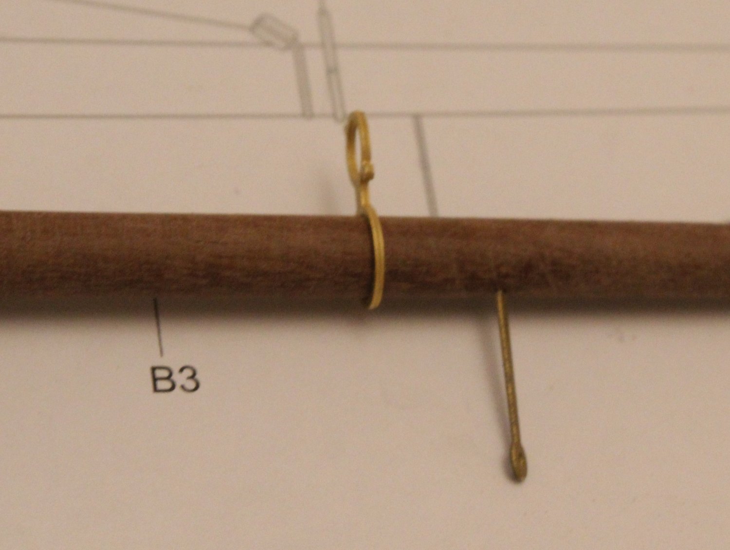
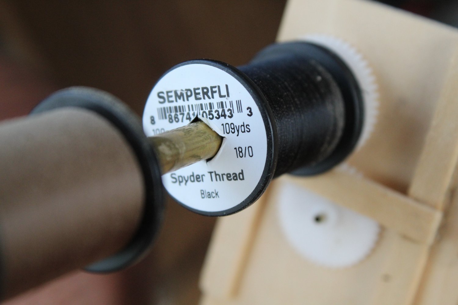
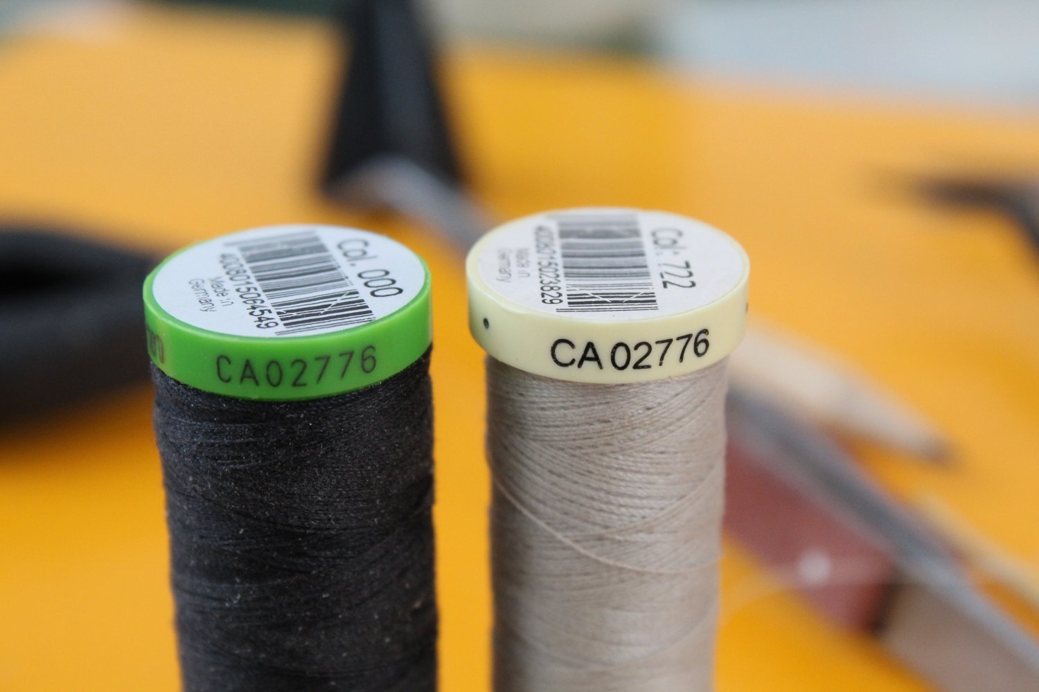
Thoughts On Adding Foreyard to Foremast As mentioned in a previous post I think it might be easier to secure the foreyard to the foremast before the stays and shrouds are rigged. The reasoning behind this is for ease of access and I know @ECK has done this with his Indy build. I plan to add the threads for the burton pendant, shrouds and stays to the mast before I add the mast cap but I will not rig the other ends so they can be kept out of the way whilst I rig the yard jeers, sling, truss pendants and nave lines. To help me fully understand the yard rigging process I have made the following notes. It has very interesting to work out the function of the various aspects of hoisting and securing a yard to the mast. Jeers The yards are hoisted up into position using the jeer block and tackles. Two double blocks are located on the yards, each situated either side of the mast. Two more triple blocks are seized to the figure of 8 wrapping around the mast (above the platform) and they hang down, so they are positioned below the platform but above the yards position. The rigging between these blocks then allows the yard to be lifted up in position. Once in position the free end(s) are belayed. Slings Once the yards have been raised to the required height, using the jeers, they are then supported by a sling arrangement. A loop is wrapped around the central point of the yard with a thimble. A second longer loop is wrapped around the mast cap with a thimble on the end. The two loops are then linked together with thread, via their respective thimbles. Truss Pendants Once the yard has been hoisted, using the jeer block and tackles, and held in place with the sling, truss pendant are used to keep the yard in place with the mast. The truss pendant comprises two parts, with each part located either side of the mast. Each pendant is a loop tied around the yard with a thimble on one end. With the yard in position the other end of each pendant is placed behind the mast and is then feed through the other pendants thimble before they are belayed to the deck via a block and tackle arrangement. Nave Line The nave line is used to hold the truss pendants in place. The nave block is located on the underside of the platform, centrally on the rear crosstree. The thread that passes through the nave block has a thimble on one end and the other end is belayed to the deck. A length of thread is passed through the thimble and each end is then secured to the truss pendants. More Thoughts And Progress on Rigging I have been doing a little bit more on some rigging and testing bits and pieces on the foremast and I thought I would this section of this post with some information regarding the seizing threads I like to use. Seizing Blocks When seizing blocks I use different threads, depending on the block and / or rigging thread size. For most 3mm and 4mm blocks I normally use Semperfli 18/0 spyder thread (black, white or beige). For larger rigging thread and / or blocks I normally use Gutterman thread CA02776 (COL722 and COL000), which is akin to 0.1mm thread. Foremast Top Section When looking at the following photo in Longridge’s book I noted there is a curved section added to the top of the mast cap. I decided to add this feature to my Indy build. I also noted the figure of 8 wrapping required which the jeer blocks are seized to. I simply cut a slice from a dowel and then added the groves for the lifts and sling rigging. The curved block top does need to be painted black. I then made the slings and lifts rigging which were then very loosely test fitted in the slots. Sorry the photo is out of focus. The lift blocks will be secured to the cap using the lashing method as shown in Fig 174 (Longridge). I tested this method in the following photo (blue arrow). The yellow arrow in the photo shows the sling test test fitted. The free end of the sling thread has been fed through the eyelet on the other end of the thread but I will seized once the yard has been fitted so the sling's thimble can be set to the required height above the yard. I have also added the figure of 8 wrapping around the top of the foremast (orange arrow). I then threaded the two triple jeer block threads in place. I have not seized the jeer blocks threads to the wrapping as this will be done once the foreyard has been added so I can ensure they set to the right height above the yard. I am about to start the manufacturing process of the lower foreyard which should keep me busy for a few days, noting my wife and I will looking after our 2 year grandson this weekend so I'm not expecting to spend any time in the shipyard.


-
I agree it is better to do that than sand away.
-
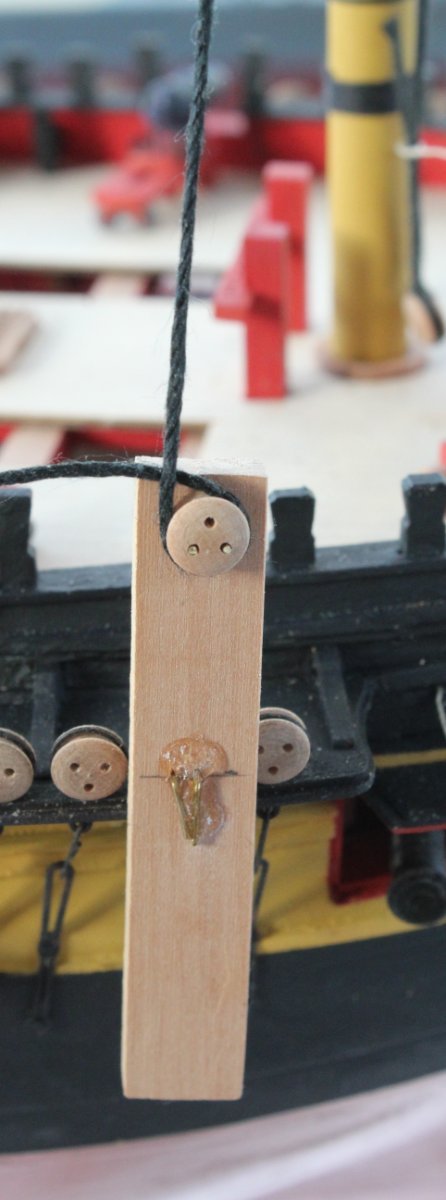
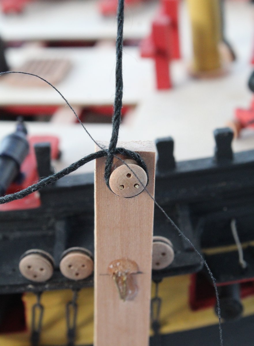
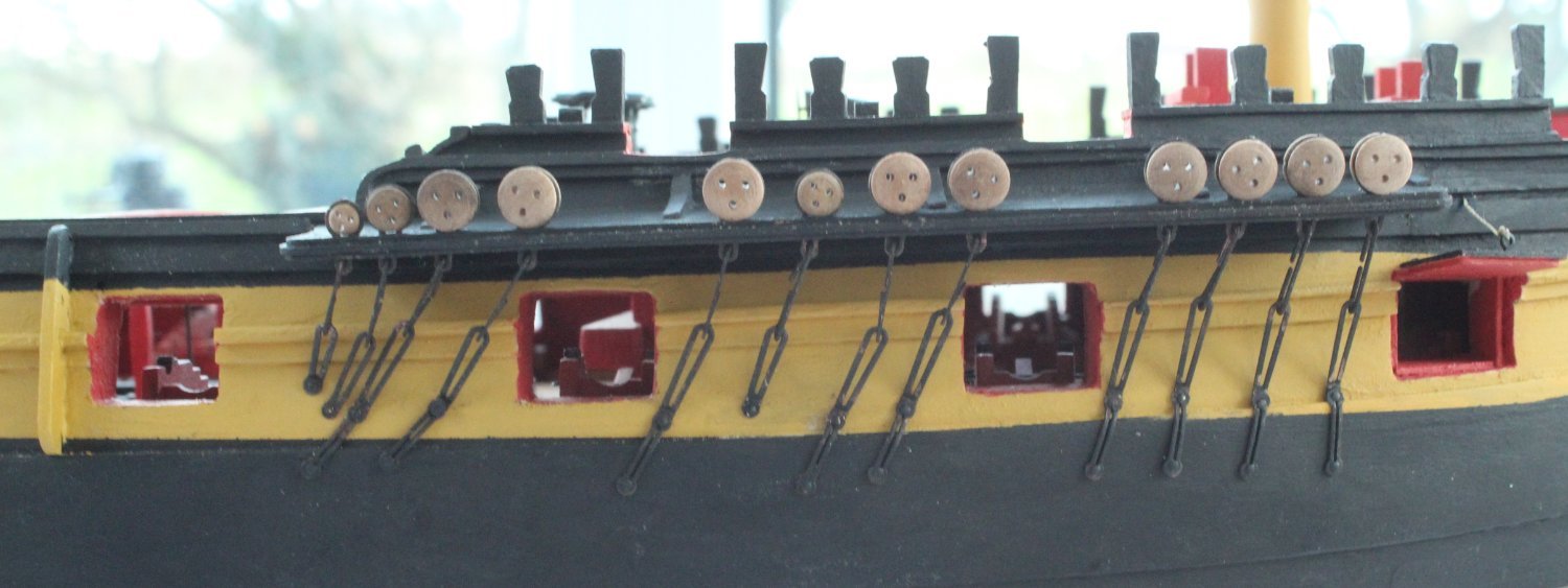
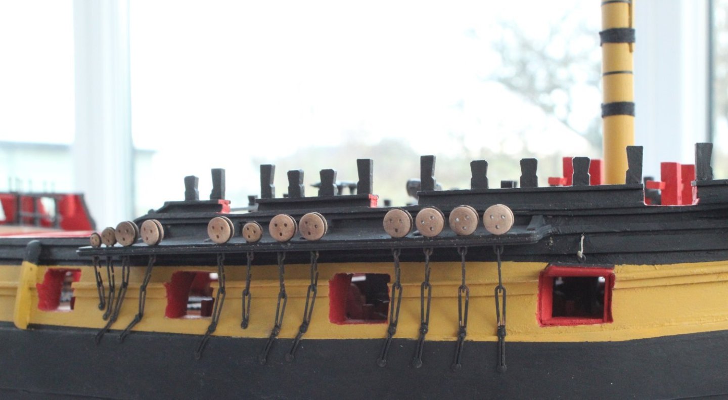
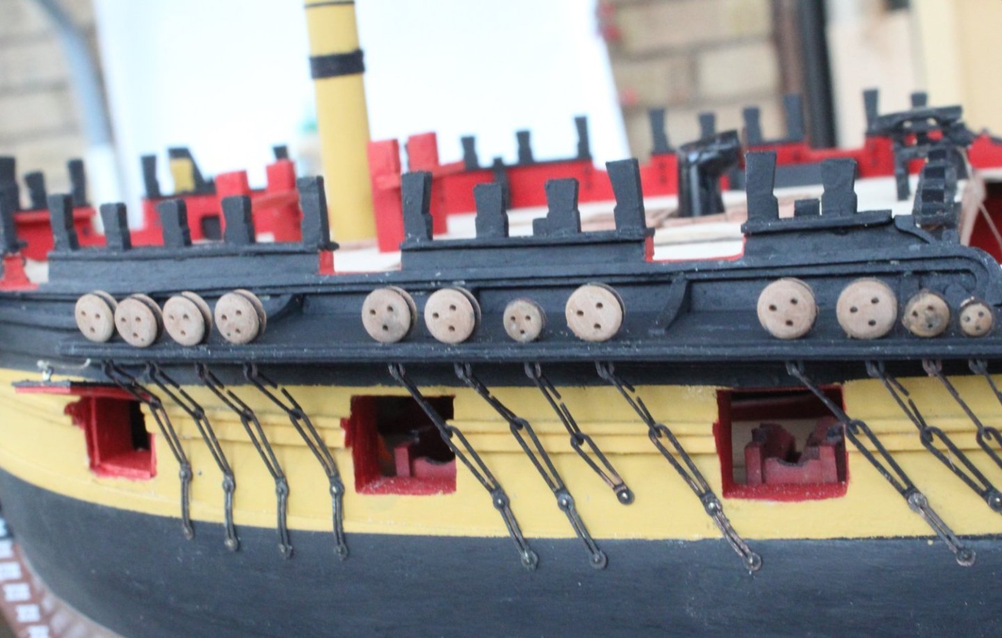
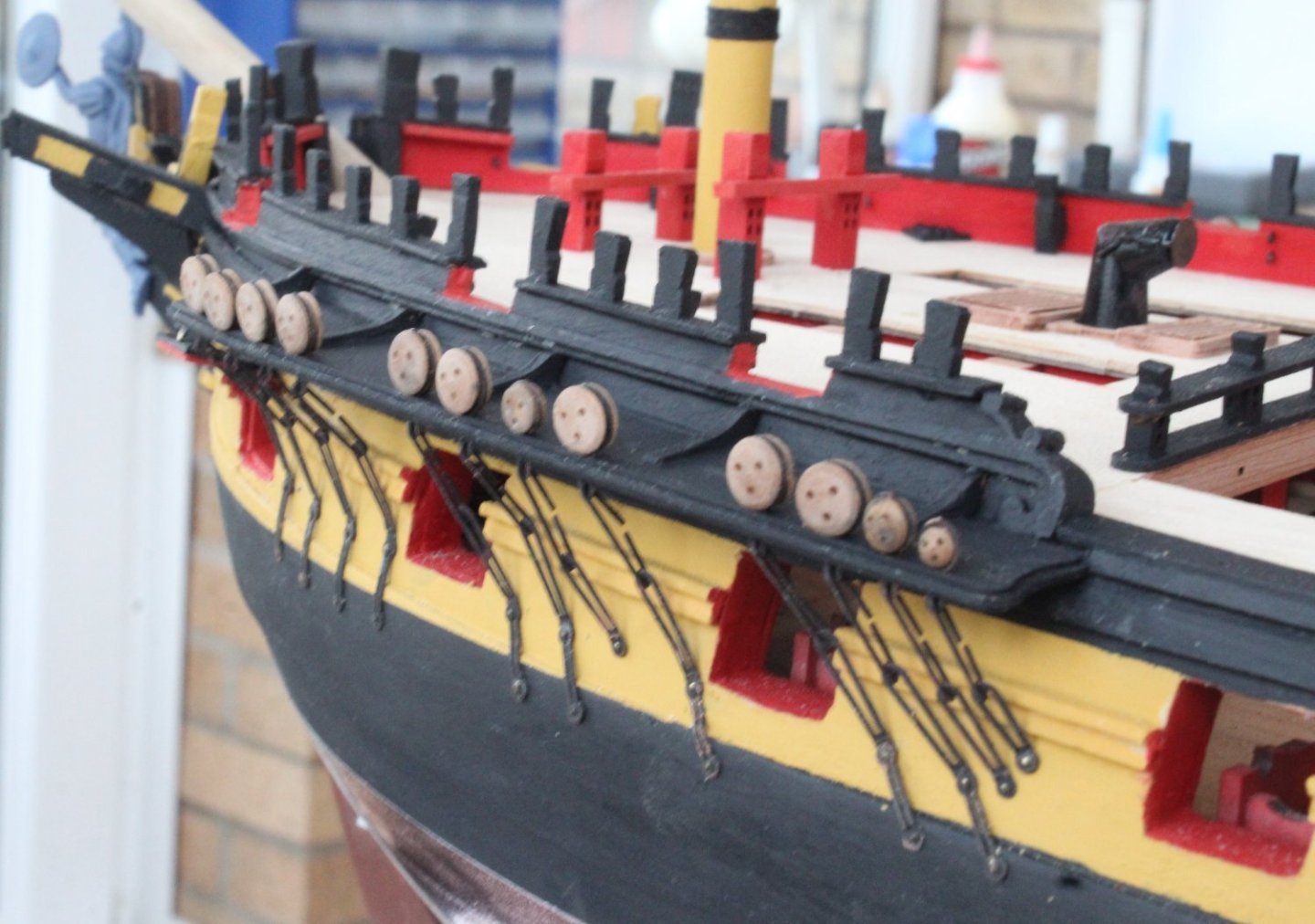
Foremast Channel Chainplates I have now added the various deadeyes, strops and chain plates to both foremast channels. I am reasonably happy with how these have turned out. I did use a diluted mixture comprising 50% wood filler / 50% titebond to fill some of the small gaps between the channel and hull.

-
The rigging looks great
-
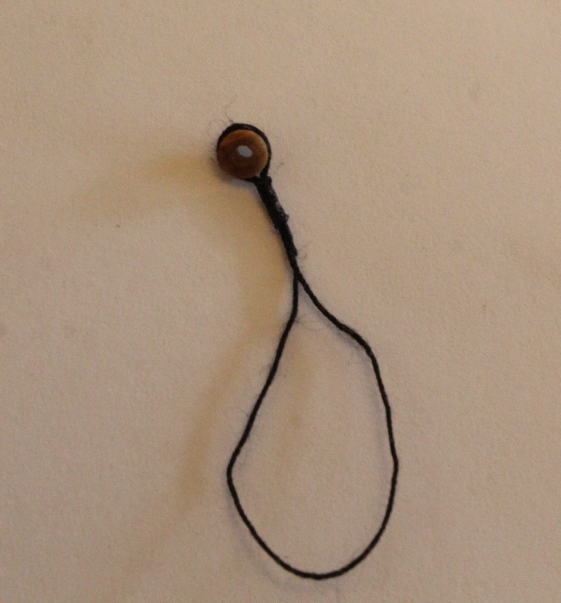
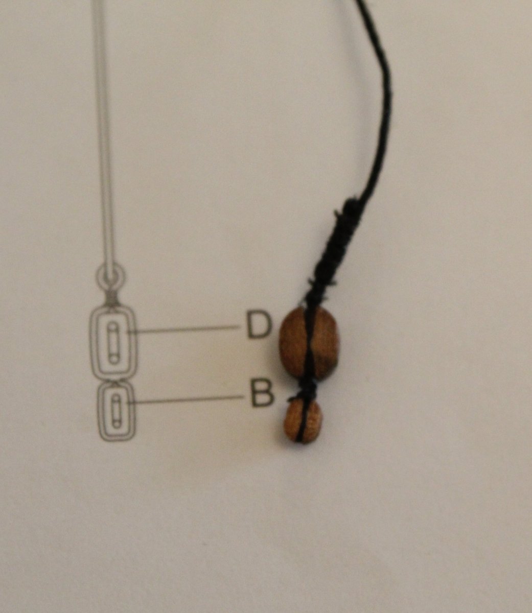
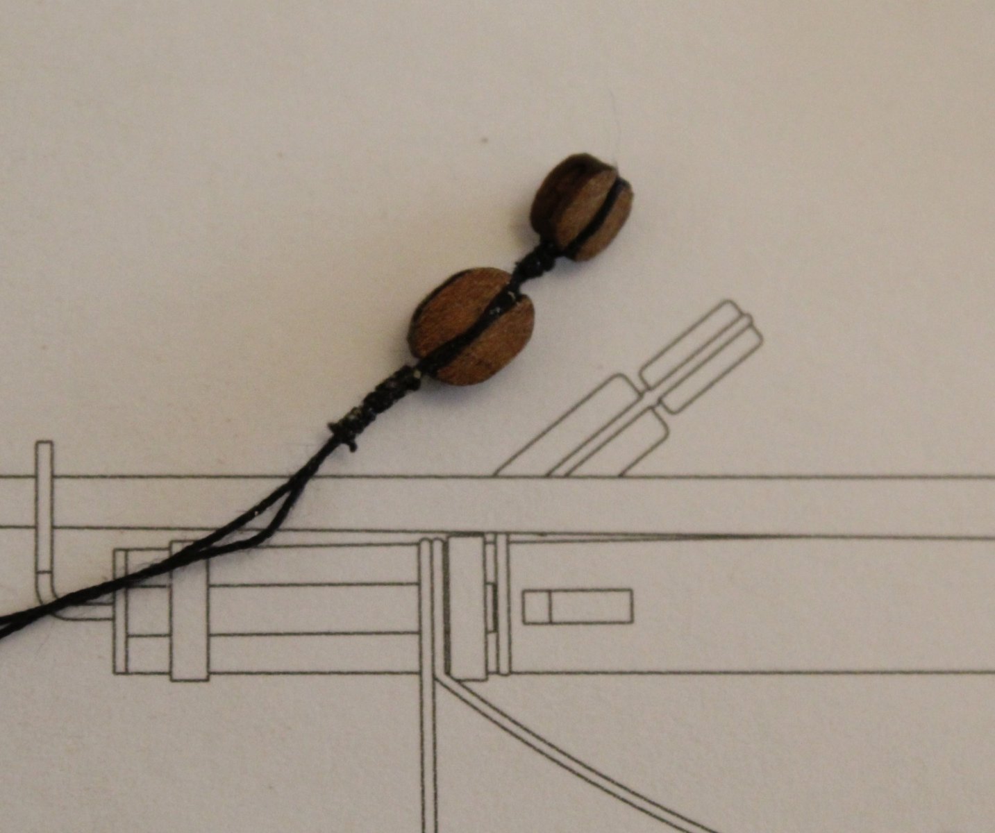
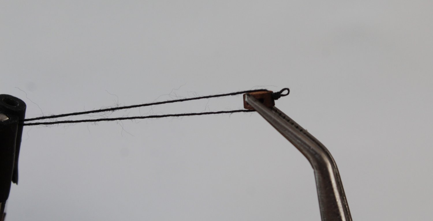
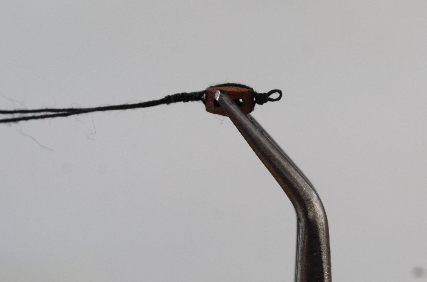
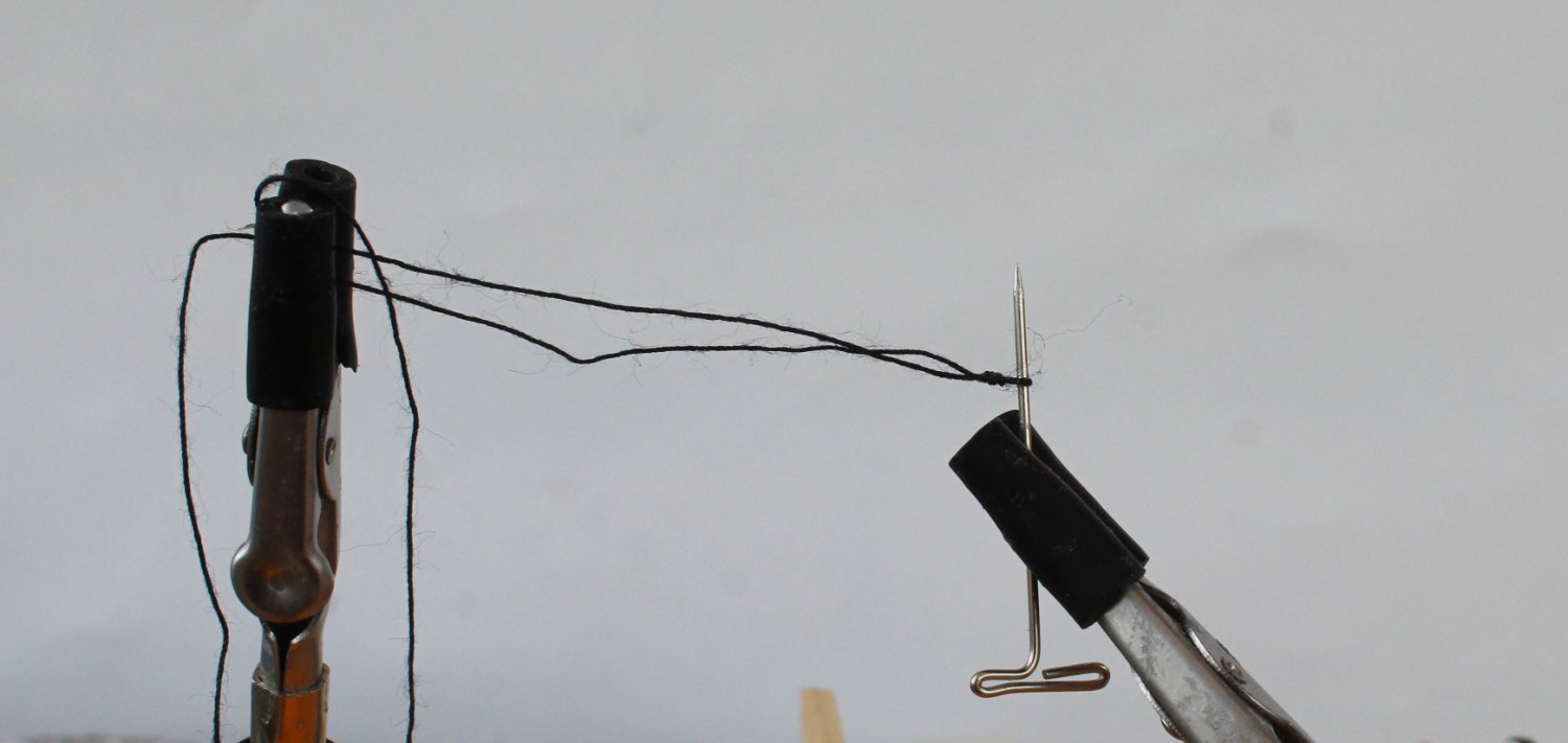
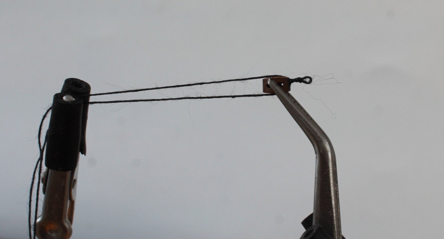
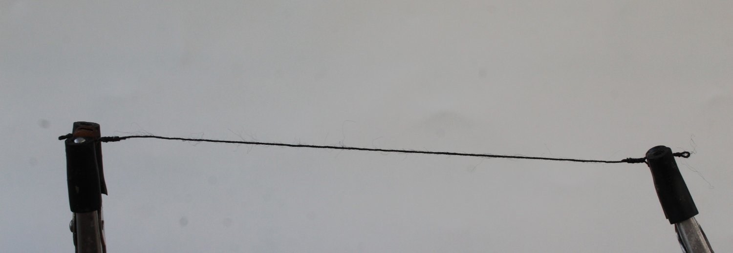
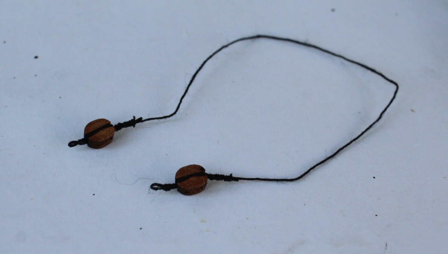
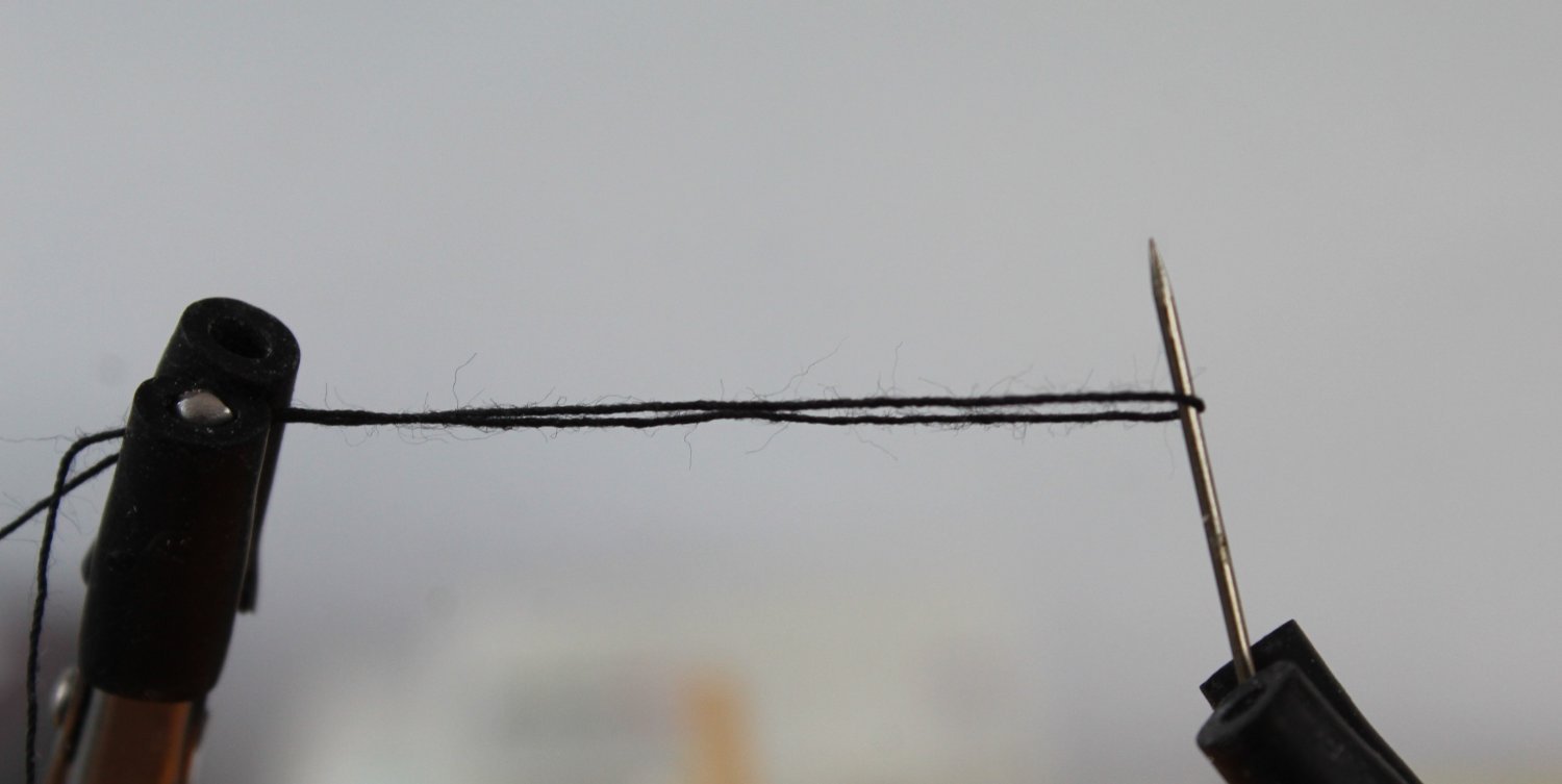
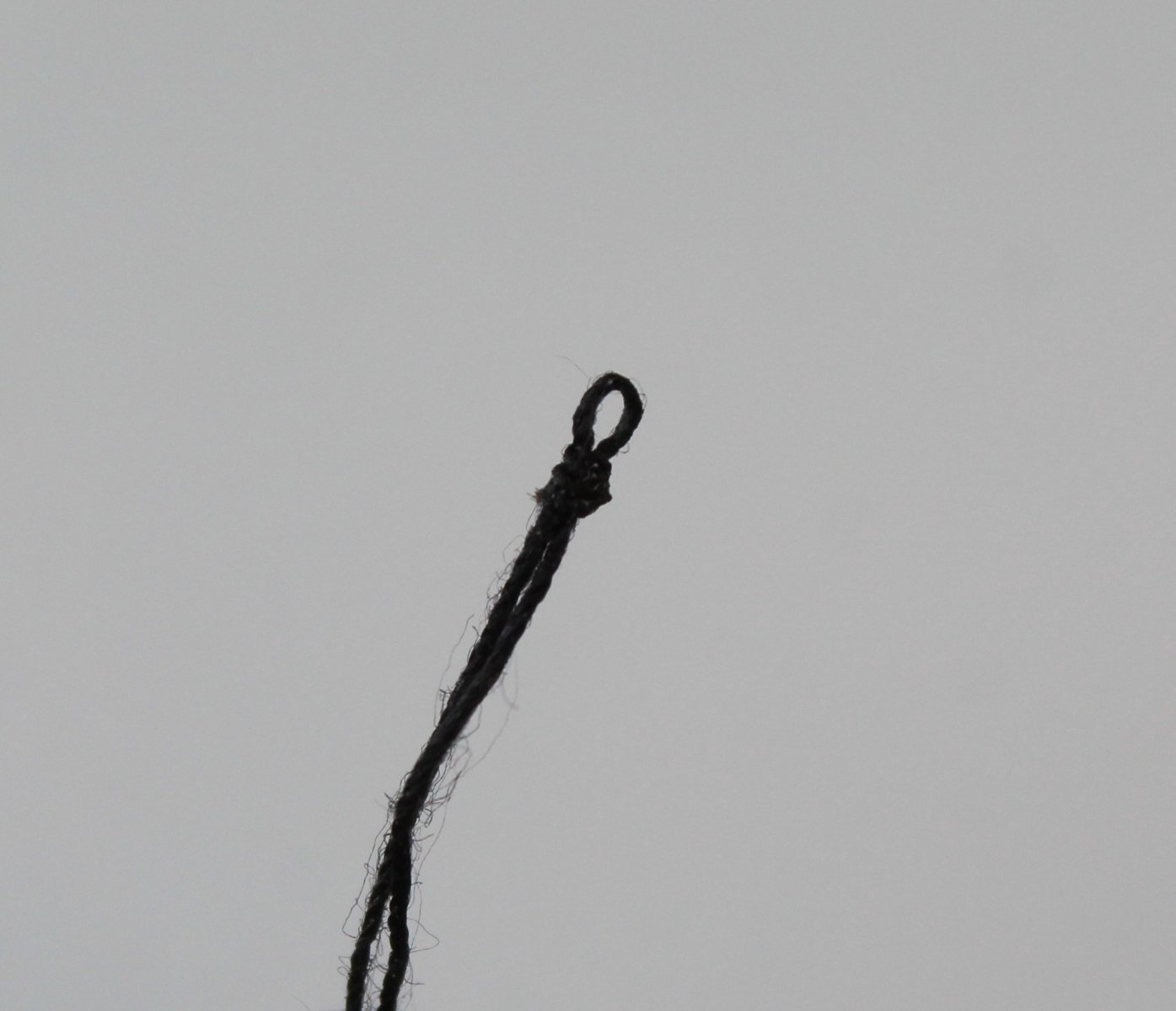
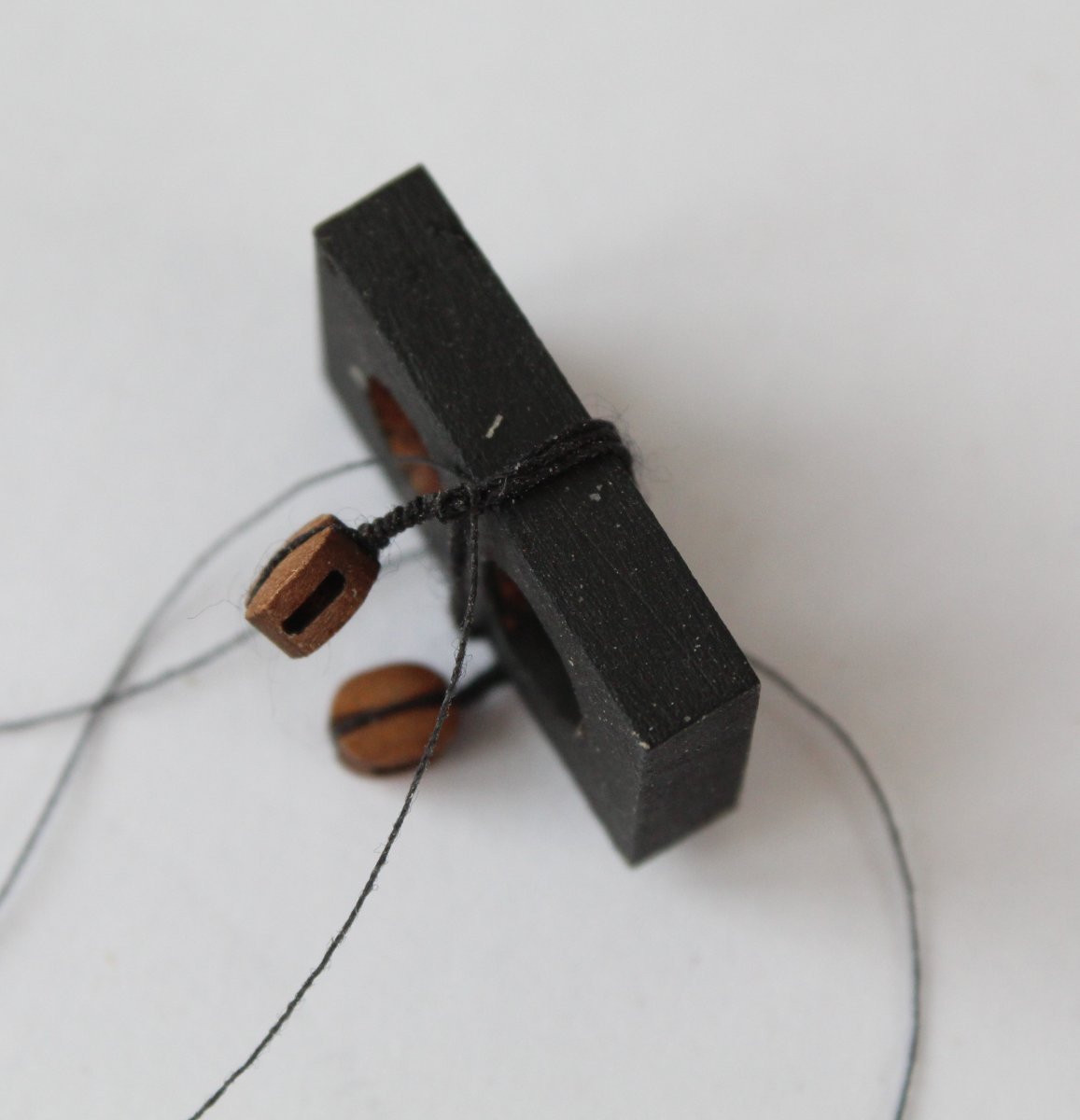
Foremast Work and Yard Lifts I have spent a bit more time working on the foremast. It was pointed out to me by @davyboy that the top of the lower foremast which located in the mast cap should be square and not round to be historically accurate. This is also shown in Figure 96 (page 166) of C Nepean Longridge's excellent book The Anatomy of Nelson's Ships. But as @chris watton pointed out most kits, for ease of building, show them as round, as once they're secured in the mast cap and painted black, it really doesn't matter as they're not seen at all. I concur with Chris's point of view. I have now added the platform rail assembly to the lower platform. The unpainted cleat in the photo below has now been painted black. Next I added the foremast channel to the hull. After the channel was pinned and glued in place I added the 5 supporting knees. After chemically blackening the strops and chainplate parts I inserted the various deadeye in to their respective strops which have been pushed in place on the channel. I normally add the eyebolts to the channel during the rigging process, as I find it is sometimes easier to add the rigging to these eyebolts before they are installed. How I Made the Yard Lifts This next part of this post is the method I used to make to yard lifts which will be added to the mast cap. The yard lifts consists of 2 x 5mm single blocks secured to a single length of 0.25mm black thread. Each 5mm block also requires an eyelet (thimble). I started with a length of 0.25mm black thread which I wrapped around a metal pin, as shown in the photo below. I am using my quad hands to hold the thread and pin in place. Using some 0.1mm black thread I added the seizing to create the loop. The seizing consisted of a series of half hitch knots, three lower and three upper. A touch of ca glue was used to stiffen the thimble before it was removed from the metal pin. I am not that worried about the fluffy thread as it will not be visible once added to the foremast. A 5mm single block was then held in the quad hand and the thread was wrapped around the block, ready for the seizing process. Using 10 lower and 10 upper half hitch knots the block was seized with 0.1mm black thread. From a previous test I required a distance of 110mm between the blocks, therefore it was a case of setting the distance and wrapping the thread around the metal pin again to form the second thimble. Once again I used 3 lower and 3 upper half hitch knots to create the thimble. The seizing was done using 0.1mm black thread and the thimble loop was stiffened with ca glue before it was released from the metal pin. The second 5mm single block was then placed in the quad hands, so it could be seized with 0.1mm black thread. The seizing, once again, consisted of 10 lower and 10 upper half hitch knots. The end result was a length of black thread with two 5mm single blocks seized at each end, each complete with a thimble.


-
Good to see you're still making progress.
-
Looks great. I am finding making the masts and yards is very time consuming.
- 233 replies
-
- 2
-
-
- Indefatigable
- Vanguard Models
- (and 1 more)
-
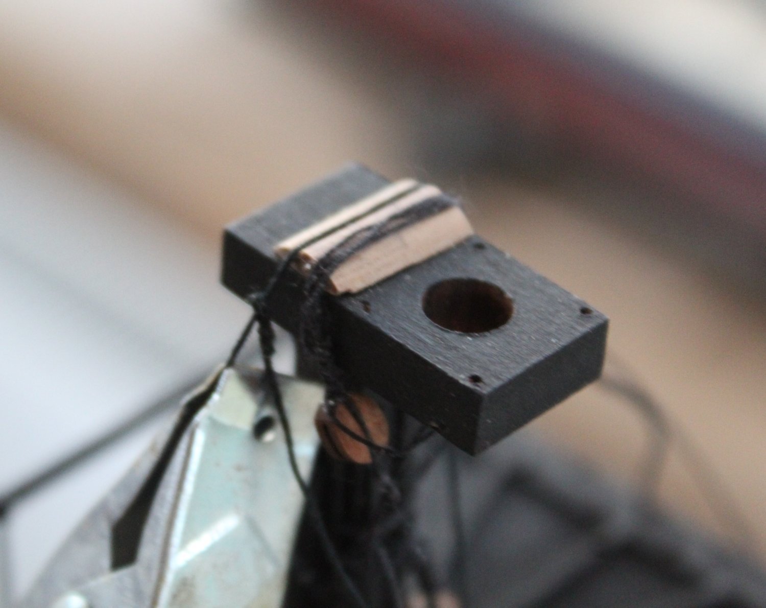
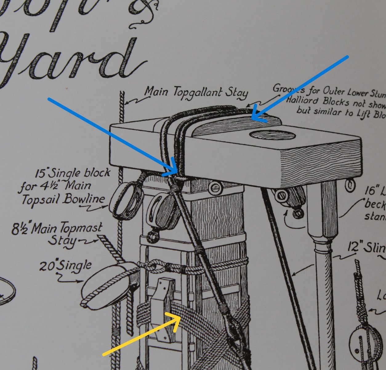
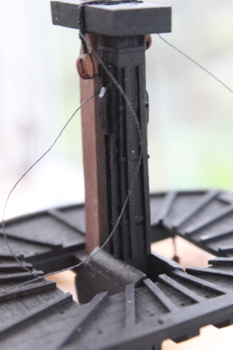
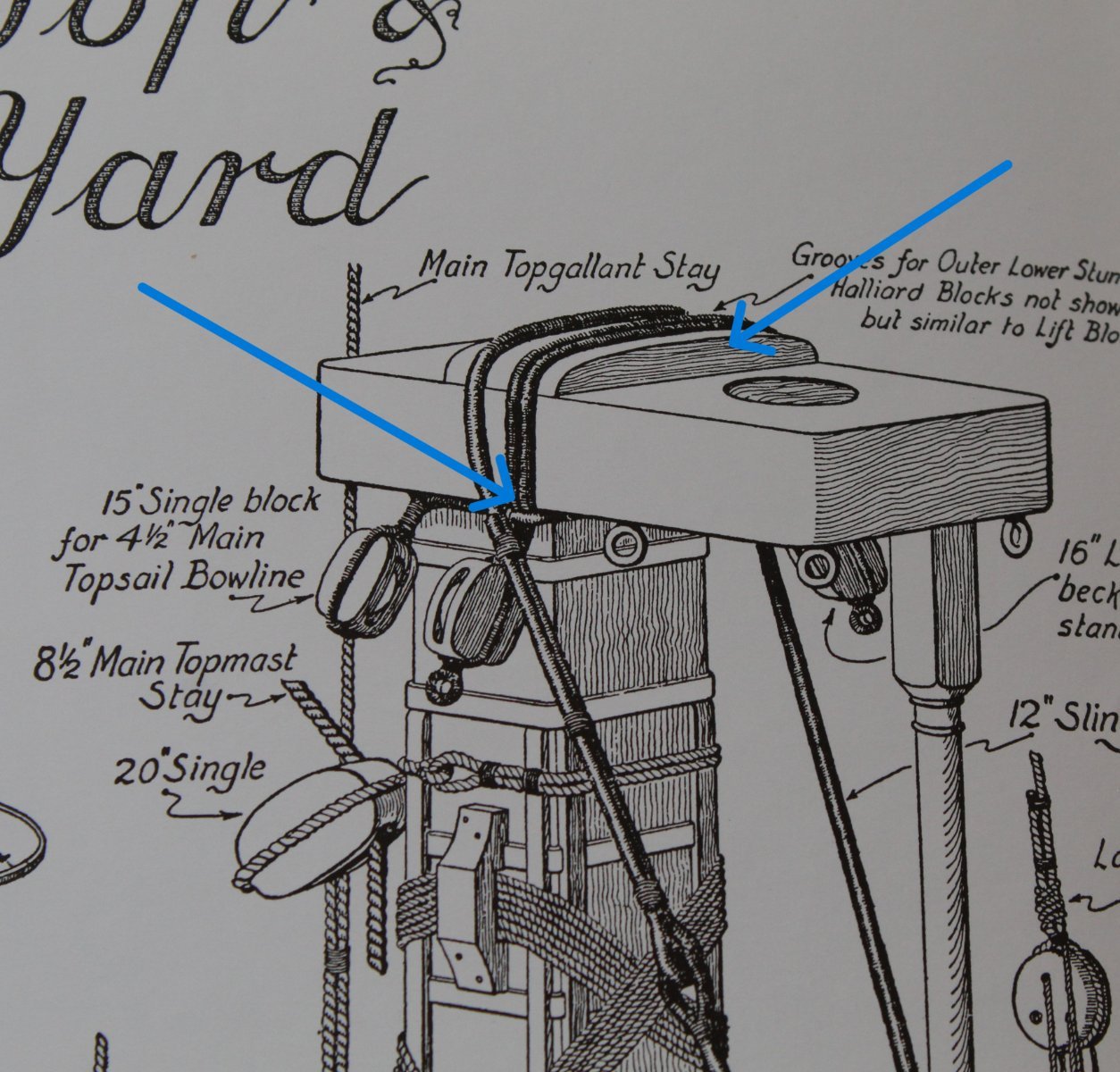
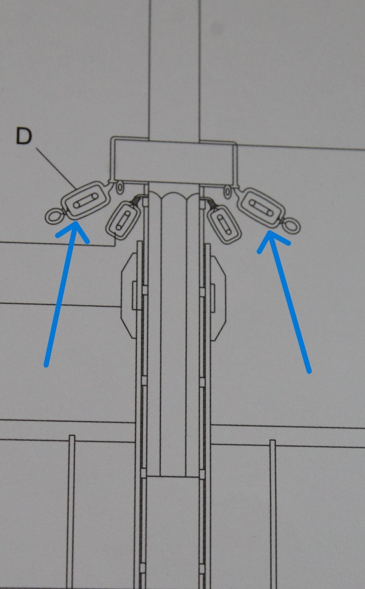
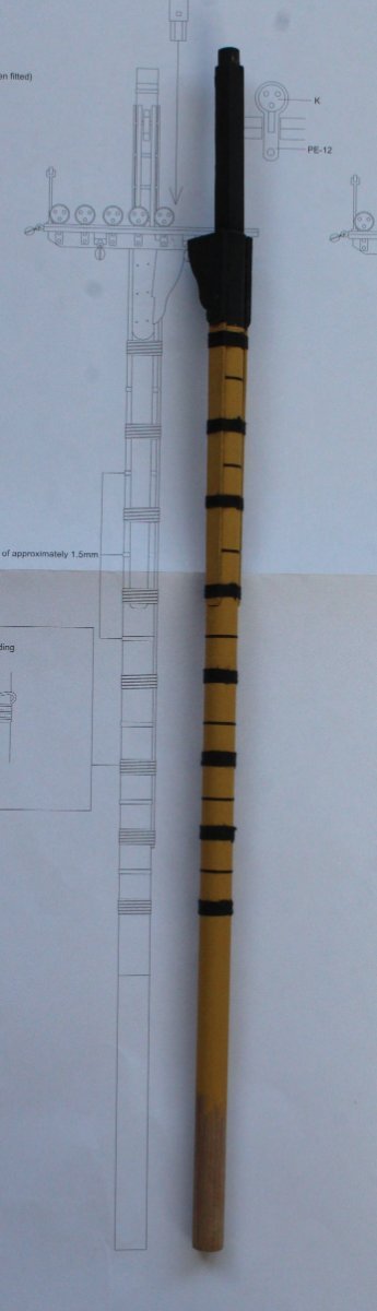
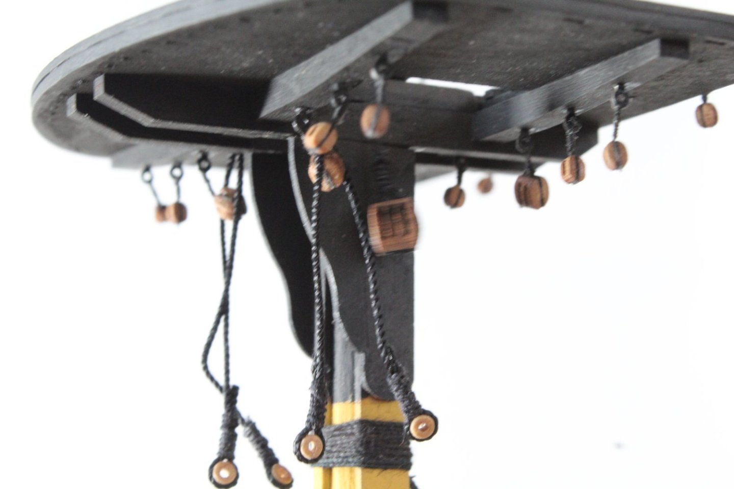
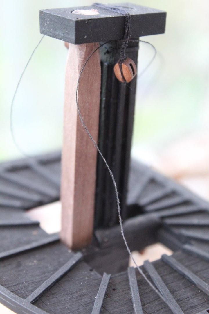
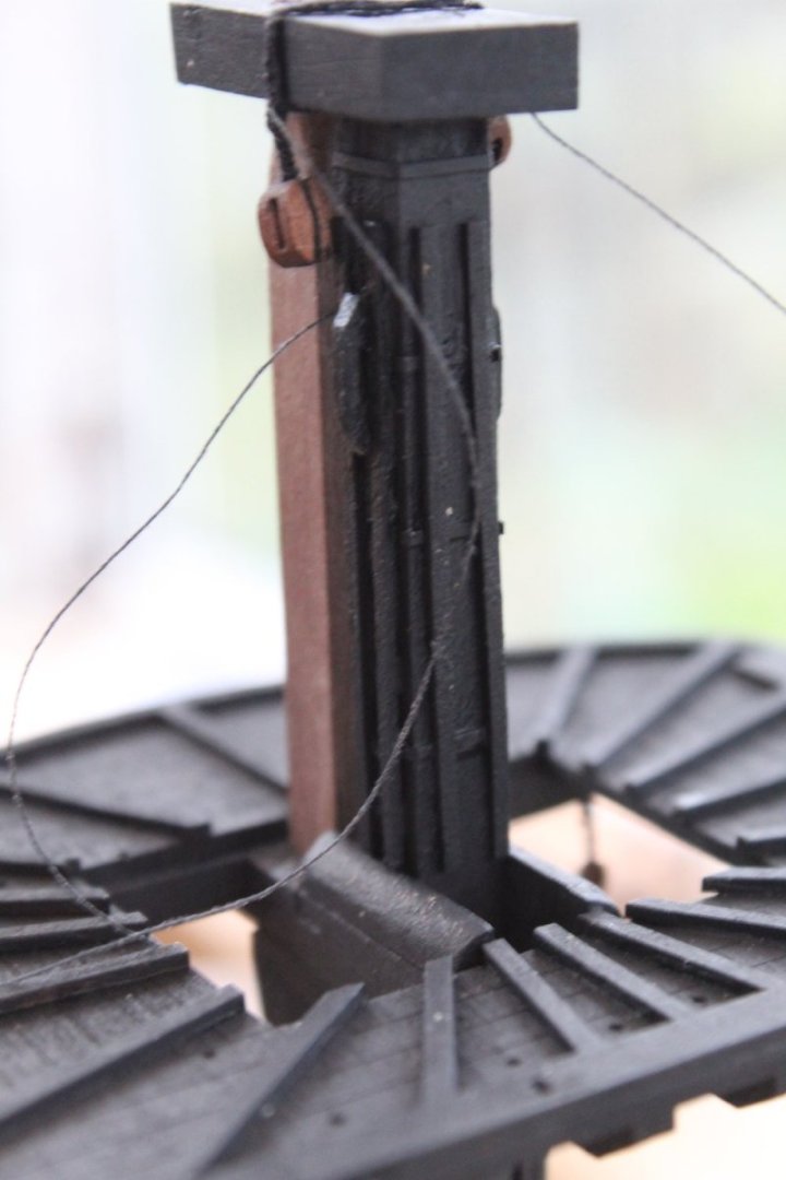
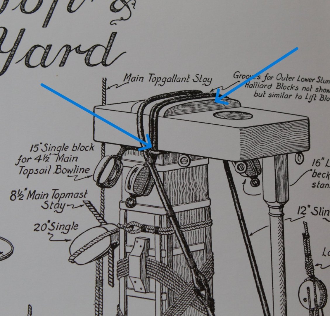
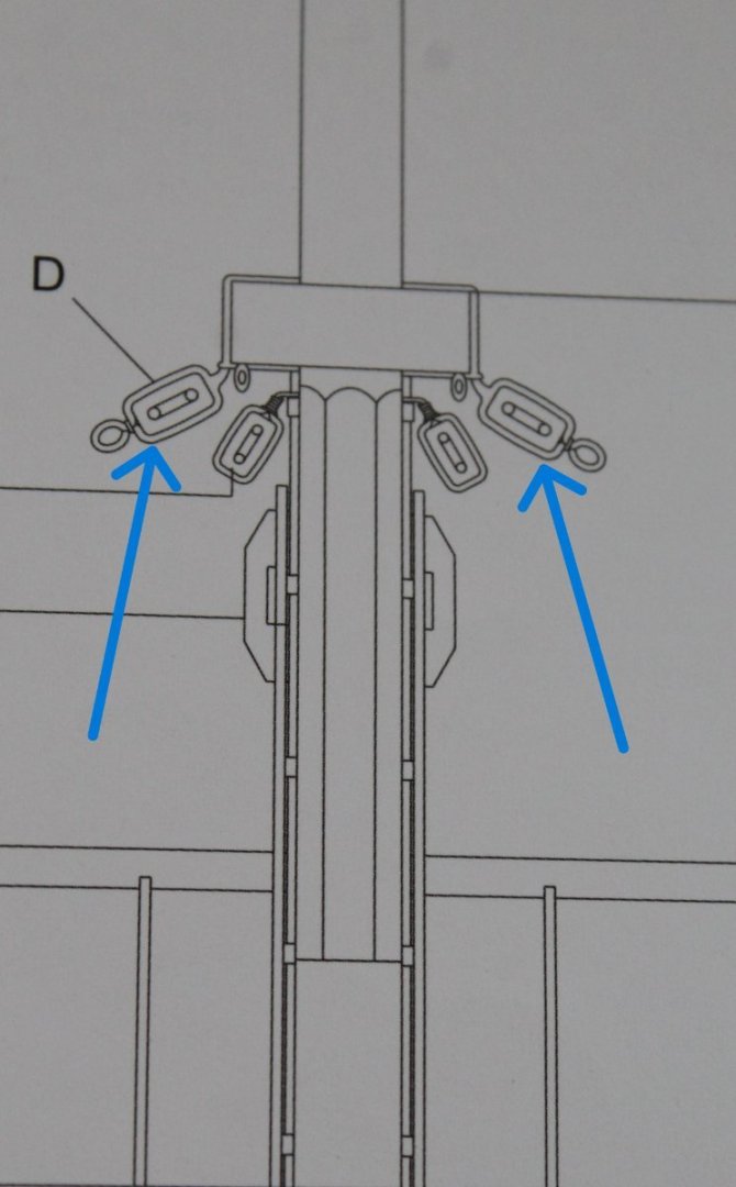
Lower Foremast Progress and Thoughts One area of the lower foremast assembly I have been contemplating is how best to secure the two yard lift blocks. These are 5mm single blocks, each with a thimble, and are wrapped around the foremast cap, as shown below (blue arrows). This arrangement is also shown in C Nepean Longridge's excellent book The Anatomy of Nelson's Ships. There are two things to note when looking at the following photo. The first is the curved section fitted to the top of the mast cap, complete with grooves for the rigging as indicated by a blue arrow. This is a simple modification to the end cap and something I might consider adding. The second thing is how the the blocks are seized at the lower point of the block, as indicated by the the second blue arrow. They look like they are held in place by the main topsail bowlines and are also seized to the sling rigging. After a little bit of experimentation I determined the distance required between two block should be 110mm, without a curve top section added. I did add some seizing to hold the blocks in place once they had been wrapped around the end cap. However this should not be necessary when they are finally fitted as they will be held in place by the topsail bowline rigging which is wrapped around the mast. The yard slings, when fitted, will also help to keep these two blocks in place. In my haste to test this method I forgot to add the thimbles to the ends of the 5mm blocks, so I will need to remake them. I also need to experiment with making and adding the 2 x topsail bowline 3mm blocks which wrap around the top of the foremast and will be positioned just below the mast cap as they will also hold the two yard blocks in place when fitted. Using a piece of 6mm x 6mm dowel with a round end I was able to simulate the lower part of the next section of the foremast assembly. This was then used to ensure the lower foremast platform was correctly set when it was glued in place. I was really pleased with the alignment. In the next photo I have also added the iron bands (using black tape) and head battens (x8) to the square section of the lower foremast. he In the final photo I have also added the two cleats which are positioned between the head battens. There is still a bit more work required to complete the lower foremast section, such as adding the main mast top stay block, the two main topsail bowline blocks, the two yard lift blocks, complete with thimbles, and the top rail assembly. The deadeye strops are also ready to be fitted. I need to make sure when these are added that I will leave enough room below the strop and above the platform for the belaying of the topmast shroud lines.

-
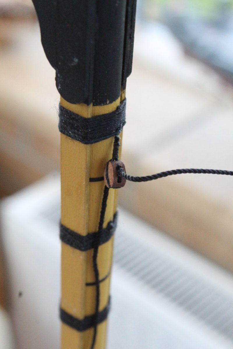
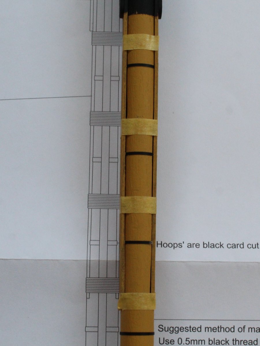
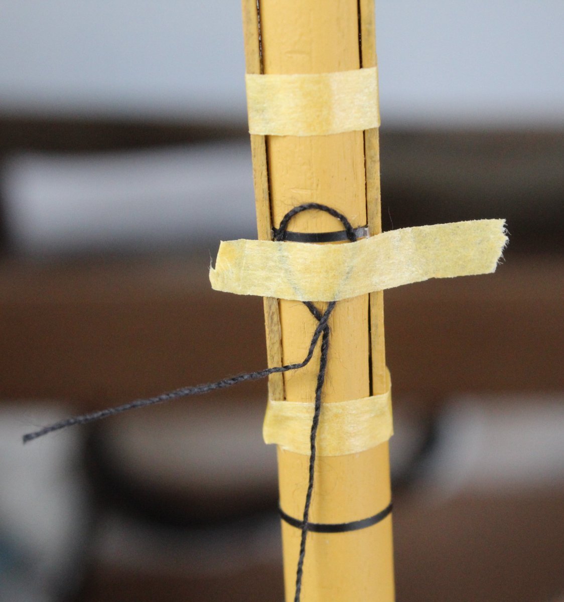
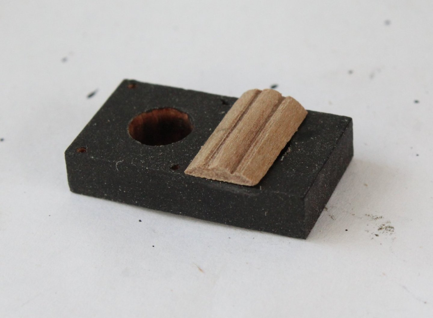
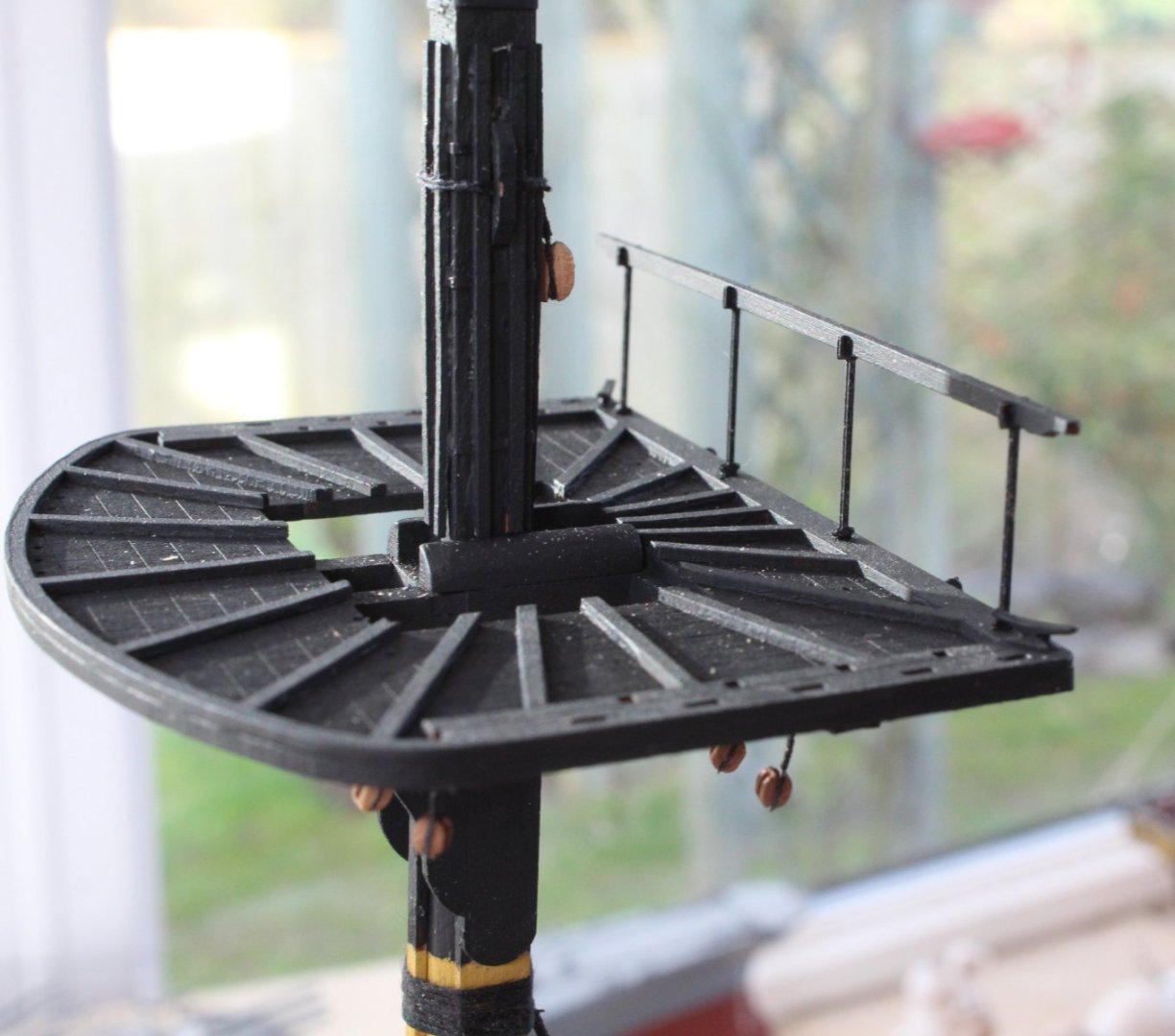
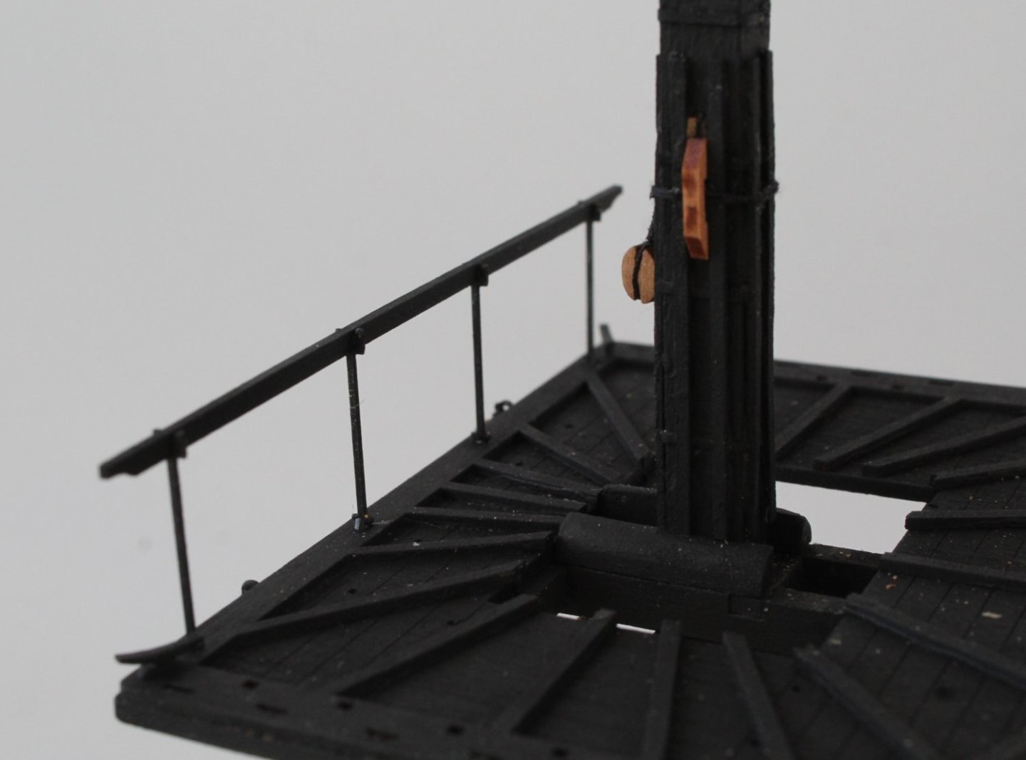
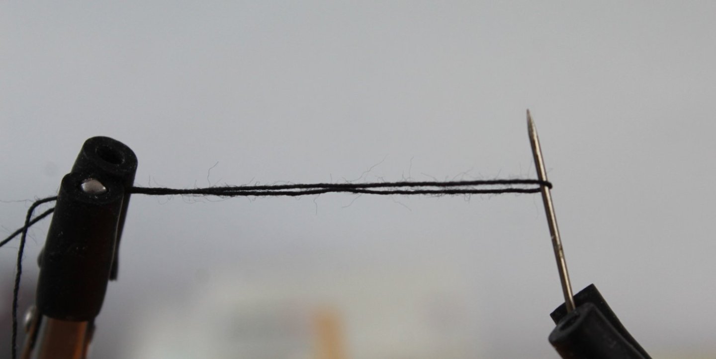
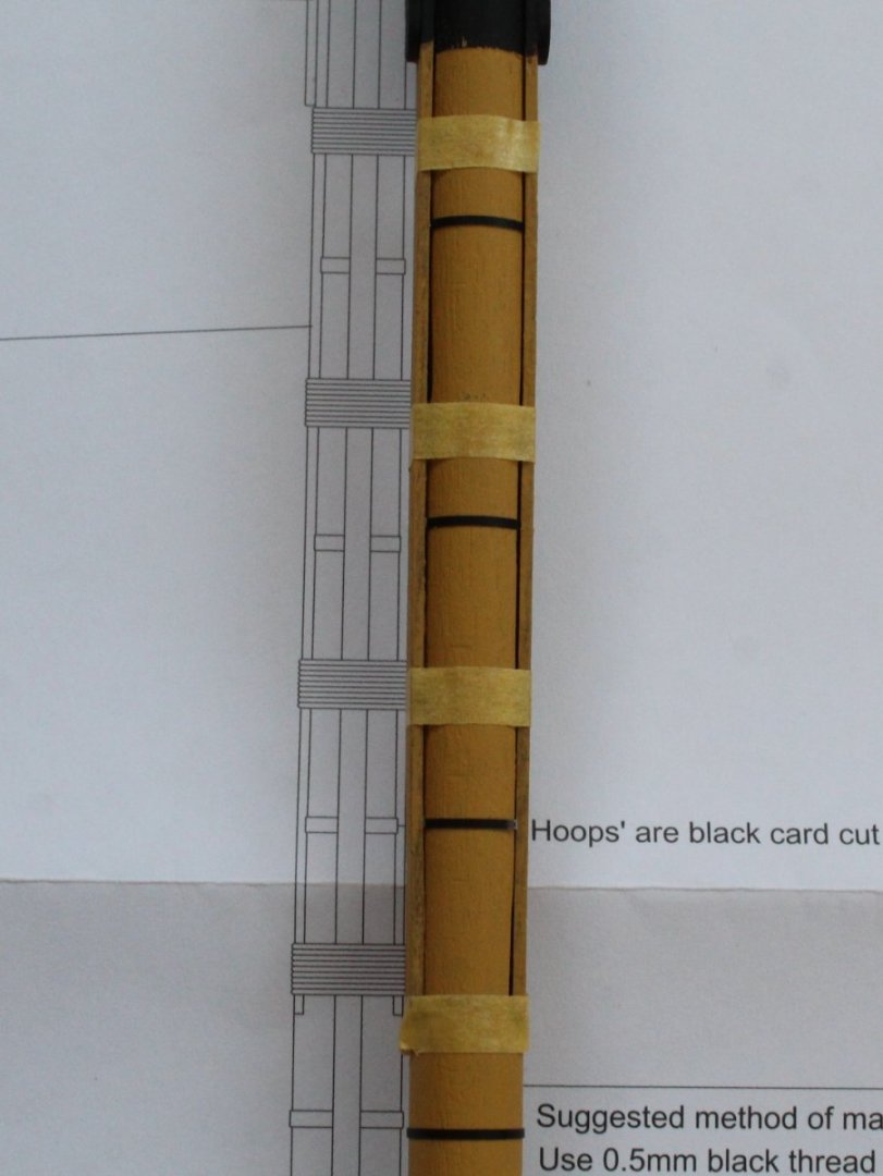
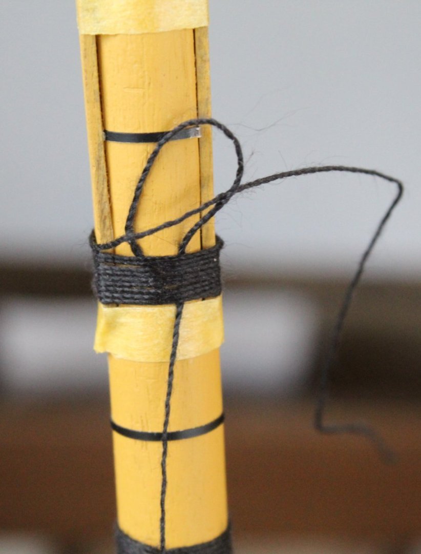
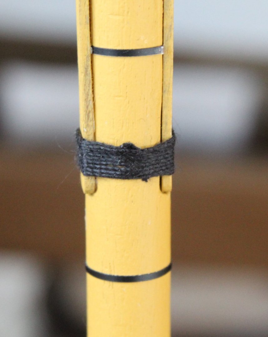
Foremast Wolding I thought I would share my method for adding the wolding to the foremast. With reference to the plan sheet I did add some tape to indicate the lower edge of each wolding. The upper tapes are in the correct position, but they look wrong in the following photo due to the angle used to take the photo. I cut a 500mm length of 0.5mm black thread and made a small loop in end which I then taped to the mast. It was then a simple case to add the wolding, by wrapping the thread around the mast 10 times. The tape securing the loop end was then removed so the thread could be passed through. The bottom end of the thread was then gently pulled down to trap the other end in the loop. The wolding was then adjusted as necessary and the excess material trimmed. It did not take too much time or effort to complete the task. There is a 5mm single block to be secured to the mast below the upper most wolding. Once the block had be seized with some 0.25mm black thread it was secured to the mast using a simple clove hitch knot. I also made sure that a sample length of 1mm black thread could be fed through the block hole, as can be seen in the photo below. Foremast Platform When working on the foremast platform I did wonder about the 8 square holes which did not seem to serve any purpose. Chris did kindly inform me that they are placements for temporary swivel gun posts, although rarely used in actual combat.


-
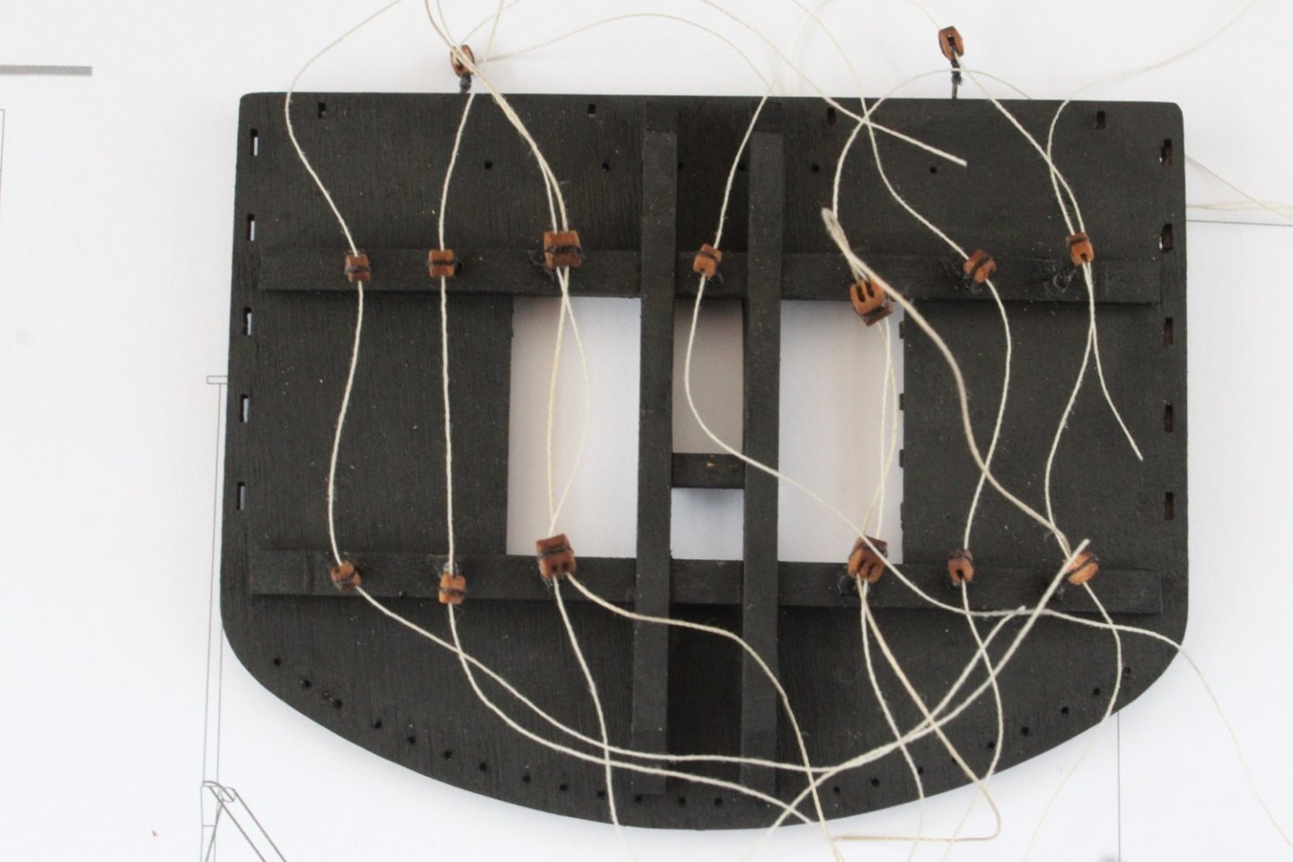
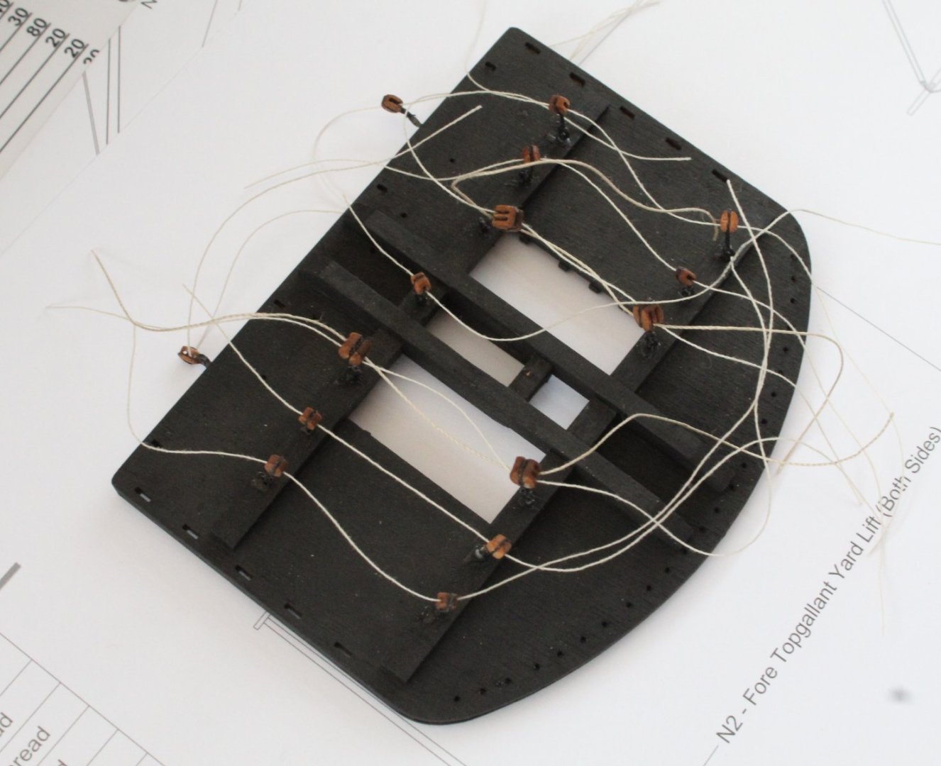
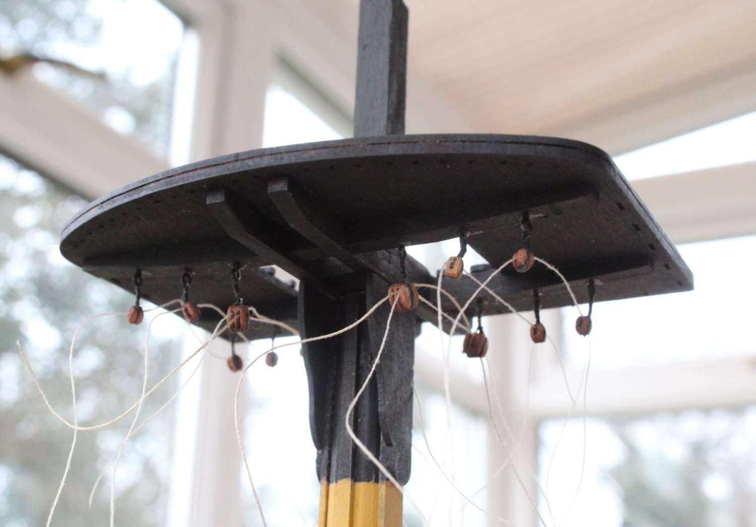
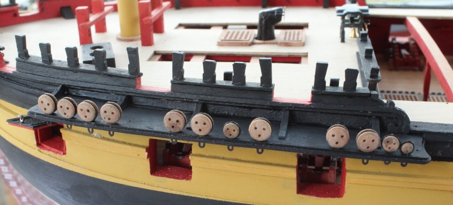
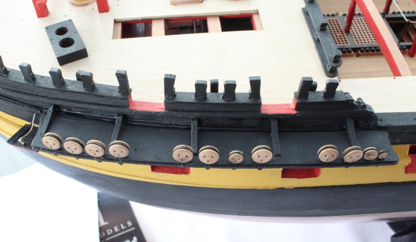
Foremast Lower Platform Blocks The lower foremast platform has a number of blocks fixed to it, via eyebolts. There are 11 x 3mm single blocks and 4 x 4mm double blocks. It was quite a time consuming task to seize the block and then to add the eyebolt, using the method detailed in my last post. The key aspect with this task was to ensure the blocks were on the required alignment for the rigging, once the eyebolts are added to the platform. It was also important to check that the required rigging thread could be fed through the block holes. Once all the blocks were completed and added to the platform I did make some test threads. One end of each test thread was stiffened with ca. to aid the threading process. As can be seen in the attached photos I was able to fit the test threads. I have noted that the top right hand eyebolt is not fully seated, which has been fixed since taking the photos. Thoughts On Moving Forward with Mast and Yard Rigging Moving forward I am now going complete the work on the lower foremast, such as adding the wolding, adding the iron banding to the square mast section above the platform, adding the various mast blocks, adding the cleats, etc. After that I will prepare the foremast shrouds so I can add the foremast channels to the hull so the chainplates are aligned to follow the flow of the shrouds. The normal process for rigging a model boat is to add the standing rigging, such as shrouds, ratlines, futtock staves, stays, etc. before adding the yards. I have always found it awkward to rig things like the yard lifts and truss pendants after the standing rigging has been added. I have often thought it might be easier to add the yards to the mast first but not sure if there will be other issues with adding the standing rigging with the yards in place. I noted that @ECK has adopted this approach on his Indy build. I am going to give this method a try on the foremast to see how practical it is. Fun time ahead.