HOLIDAY DONATION DRIVE - SUPPORT MSW - DO YOUR PART TO KEEP THIS GREAT FORUM GOING! (Only 72 donations so far out of 49,000 members - Can we at least get 100? C'mon guys!)
×

archjofo
-
Posts
1,497 -
Joined
-
Last visited
Content Type
Profiles
Forums
Gallery
Events
Everything posted by archjofo
-
 Hello fellow model builders, Thank you so much for the likes and your kind Christmas wishes. I hope things will continue here soon.
 -
@GeorgeKapas A beautiful model ship!
-
Hello, These are so-called timber hitches (see LINK ). A knot that was used in various rigging situations, including for temporarily securing the bowlines. However, this was primarily used in the British Navy, as already mentioned.
-
@Kenchington Hello Trevor, Thank you, very exciting that you experienced the Rose before her ‘career’ as Surprise. Your note on English practice complements the French sources wonderfully and makes the differences even clearer.
-
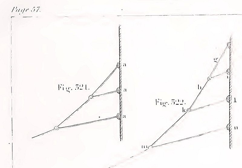
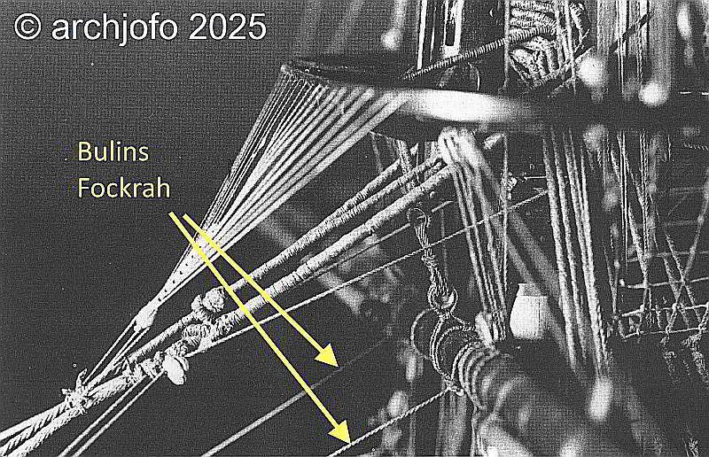
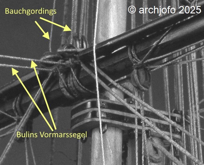
Bowlines and Bridles – Boulines et branches In continuing my research on the bowlines (boulines) for my French corvette, I came across an intriguing national distinction that manifests not only in theory but also in practical model execution. I have since identified a differing treatment of bowlines when sails are struck, between British and French practice. The aim of these measures was to prevent the lines from becoming entangled and to ensure immediate readiness when re-rigging. These differences are well documented in contemporary sources and observable in period models: a) British Practice: British manuals such as David Steel (1794), Darcy Lever (Sheet Anchor, 1808/1843), and Brady (The Kedge Anchor, 1841) depict bowlines fitted with spliced-in thimbles, through which the bridles were rove. Lever states explicitly: “The bowlines are rove through thimbles spliced into their ends, to which the bridles are attached.” Source: The Young Sea Officer’s Sheet Anchor, Darcy Lever, p. 57, 1843 Accordingly, the British rigged the bowlines together with the bridles to the outer yardarms. This arrangement was certainly robust, but less flexible when striking sails, as bowlines and bridles had to be handled as a single unit. Source: K. Schrage – Rundhölzer, Tauwerk und Segel, p. 144 b) French Practice: Baudin (Manuel du jeune marin, 1828) notes that bowlines were rolled up and secured to the mast or yard after the sails were furled — “roulées et assujetties au mât ou à la vergue.” He does not elaborate on the exact method of securing them to the yard. However, his description suggests that the bridles remained attached to the sail. This interpretation is supported by illustrations in the Atlas du Génie Maritime, where bowlines are shown fastened to the bridles using toggles. This solution facilitated rapid bending and unbending of the sails. The bowlines of the mainsails require separate consideration, as discussed in a previous contribution of mine. Source: Atlas du Génie Maritime On the period model of La Créole, as well as on numerous other models in the Musée national de la Marine, one can observe bowlines secured amidships on the yards, without bridles. In the case of La Créole, the bowlines in this example appear to be connected to the buntlines via eye splices or stopper knots, and thus stowed securely. Source: Detail from the original model of La Créole, Musée de la Marine, Paris Source: Detail from La Flore, Frégate de 18, Musée de la Marine, Paris, 1806 Personal Conclusion: The French employed toggles at the bridles and secured the running ends of the bowlines amidships on the yard, where possible, e.g., in conjunction with the buntlines — in my view, a practical solution that facilitated swift re-rigging. The British, by contrast, preferred spliced-in thimbles at the ends of the bowlines, through which the bridles were rove — a permanent and solid connection, but likely less flexible when striking sails. This reveals a clear national differentiation, as seen in many other rigging elements. As a result, I now need to revise the detail of the bowlines on the fore yard, which I had mistakenly and prematurely executed in analogy to British practice. It seems important to me that such details shouldn't be viewed too absolutely. Depending on the ship type, time period, or source, different solutions may have existed side by side—and therefore, variants that deviate from the "schema" are not automatically wrong. I welcome any feedback or additions — especially references to French sources that further illuminate the use of toggled connections.

-
@matiz These plans look familiar to me...😁
-
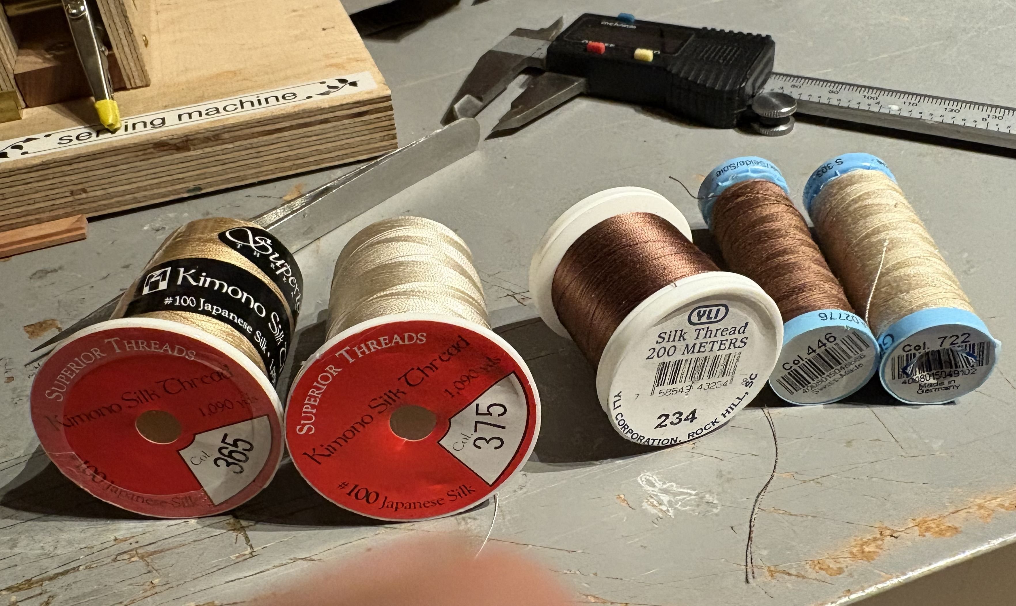
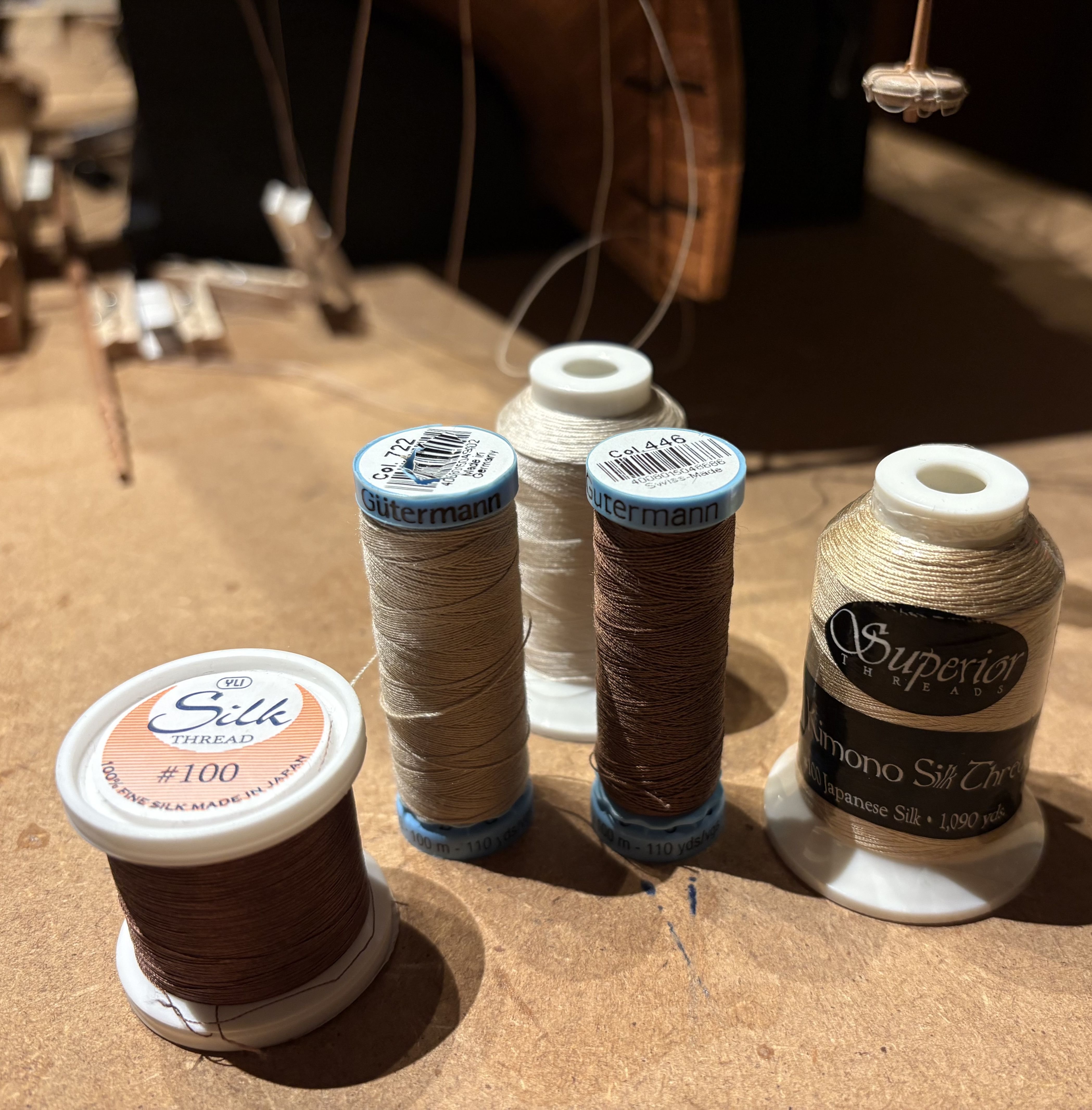
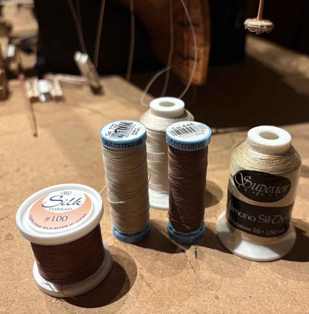
@Loracs Hello, No problem, of course I'll show you which yarns I use as the raw material for making my ropes. It's silk yarn, which isn't entirely undisputed in terms of durability. Nevertheless, I chose it because, in my opinion, it's the ideal raw material for model ropes. You can read an interesting post by Greg Herbert about the use of silk in model making and in general in my topic: LINK I use silk yarn from Gütermann, Ylk, and Kimono. The following pictures also show the color numbers used. If you have any further questions, please feel free to contact me.

-
@Pirate adam Hello, Thank you very much for your appreciative words—they truly mean a lot to me. Regarding your generous remark about this build log becoming a “valuable resource on rigging,” I’d like to add a small clarification: just as with ship construction, rigging practices must always be understood within their specific historical and geographical context. My research and conclusions are focused on the early to mid-19th century, particularly within the French naval tradition. Sharing these findings feels natural to me—especially since I continue to benefit greatly from the many outstanding build logs and discussions here on the forum.
-
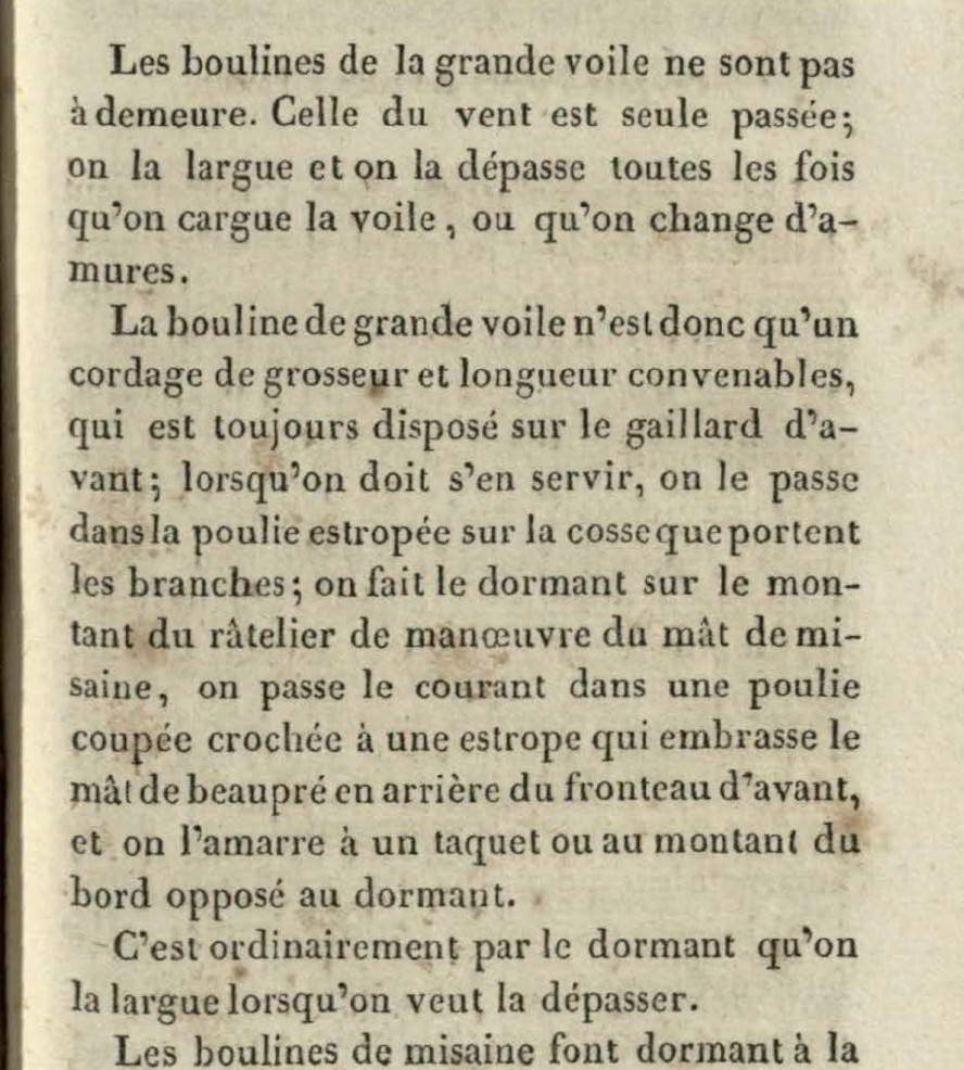
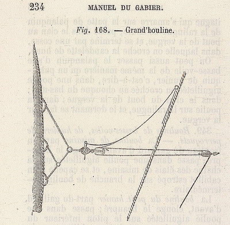
Rigging of the Mainsail Bowlines – Boulines de grande voile In the meantime, I have been able to clarify the principle of how the mainsail bowlines were rigged on my French corvette through the study of contemporary technical literature. It is important to maintain both the chronological and geographical context. My findings are consistent with the observations made on the period models in the Musée national de la Marine. The mainsail bowlines were led through snatch blocks (fr. poulie coupée), which were attached amidships on the deck abaft the foremast and belayed, for example, at the pin rail behind the foremast. Since the mainsail bowlines of larger ships required considerable force, they were usually double-purchased. Accordingly, blocks were fitted at the ends of the bowline bridles through which the bowlines were rove. Whenever the bowlines were not in use, they were unrove from the snatch blocks. Whether La Créole actually carried double-purchased bowlines could not be determined with certainty. What is decisive, however, is a finding from contemporary literature: The mainsail bowlines were not permanently rigged, in contrast to those of all the other sails. They were only bent on when actually needed; otherwise, they were kept ready for use on the foredeck. Source: Nouveau Manuel complet de Marine by M. Verdier, Capitaine de Corvette, Paris 1837, p. 175. This also explains why, on the period models (rigged without sails) in the Paris museum, bowlines are always to be seen on the other yards – but never on the main yard. The same applies to the original model of La Créole. For this reason, I will consequently not represent mainsail bowlines on my model. Nevertheless, for illustration, I show here how the rigging of the mainsail bowlines would have looked in principle: Source: Manuel du Gabier, Paris 1875.
-
@druxey @wefalck @JerryTodd Hello, I would like to expressly thank you for your precise and helpful contributions on the question of the routing of the mainsail bow lines. The different perspectives on historical practice, especially in the English context, as well as the technical information on possible interference with the headsail rigging, have greatly helped me to consider the issue in a more nuanced way. Your assessments contribute significantly to critically questioning the plausibility of the solution presented in Boudriot's monograph. I will incorporate the suggestions into my further planning and look forward to further discussions.
-
Supplementary Note on the Routing of the Mainsail Bowlines To further illustrate the issue described above regarding the routing of the mainsail bowlines (blue lines), I’d like to share two visual references. These are based on cropped images of my model and excerpts from Boudriot’s monograph, and are intended to clarify the technical challenge posed by the forward-leading arrangement. From my perspective, the solution depicted in the monograph—leading the bowlines over the foredeck—raises questions, particularly with regard to potential interference with the foremast rigging. This configuration seems unusual when compared to other period models, where bowlines are typically belayed aft of the foremast. I’d be very interested to hear your thoughts on this matter, and whether similar arrangements have been documented elsewhere.


-
After the Summer Break – Continuing My Build Log The days are growing shorter, the world outside is quieter—and with autumn comes a renewed passion for model building. After a brief creative pause, I’m looking forward to resuming work on my French corvette La Créole. As a starting point, I’ve recently focused on clarifying the belaying points in the foredeck area, in order to complete the rigging of the fore yard as well as the jibboom and flying jibboom. In this context, I’ve created two illustrations (based on cropped images of the original model and excerpts from J. Boudriot’s monograph), which I’d like to share here. These sketches are not yet complete, but they serve as a foundation for further development and offer a glimpse into the research that preceded this stage. Once again, working through these details has shown how multifaceted and rewarding the engagement with historical sources, technical drawings, and contemporary models can be—and how much it contributes to the vitality of a project like this. One aspect that remains unclear to me is the routing of the mainsail bowlines, as depicted in Boudriot’s monograph. According to his illustration, the bowlines are led forward over the foredeck—a solution I hadn’t encountered before. Based on my current understanding—and after reviewing several period models—bowlines are typically belayed aft of the foremast. Routing them over the foredeck seems not only unusual but also technically problematic, as it could potentially interfere with the foremast rigging. This point therefore remains unresolved and will require further investigation. I look forward to exchanging ideas with you and am eager to hear your thoughts and suggestions regarding the sketches I’ve shared.


-
Roter Löwe 1597 by Ondras71
archjofo replied to Ondras71's topic in - Build logs for subjects built 1501 - 1750
Hello Ondrasch, First of all, let me say you're building a wonderful model with outstanding craftsmanship. I'm also truly honored to be mentioned in your build log—thank you for that. I'd like to offer a small tip: If you carve a shallow groove into the round wood used for attaching the deadeyes—just as shown in my photo—it becomes much easier to push the needle through. It’s a simple adjustment that can really streamline the process and improve alignment. Looking forward to seeing more of your progress. Your work is a pleasure to follow!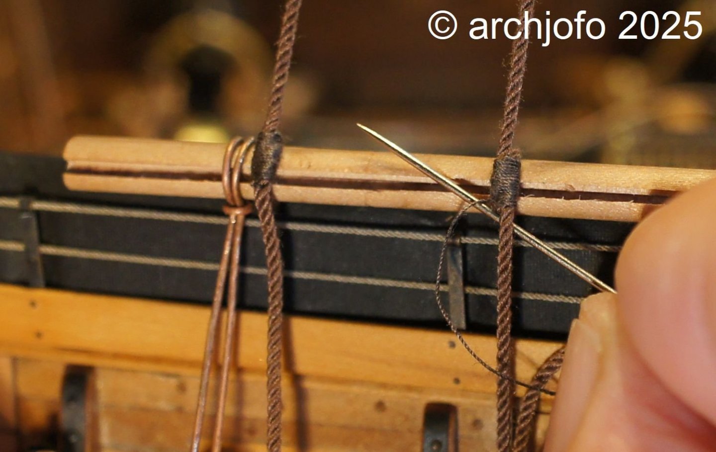
-
Hello Eberhard, I was a little surprised when I read that you also cited F. A. Coste as a source. But, as always, excellent research.
-
Photo Book - LA CRÉOLE CORVETTE DE 24 BOUCHES À FEU 1827 DU L’INGÉNIEUR LEROUX Sometimes a project needs a little break – and sometimes you need something to remind you why you started it. Since I can't currently continue working on the running rigging of my French corvette, La Créole, for personal reasons (my son's house building and a few age-related aches and pains...), I've created a photo book: as a source of motivation, a look back, and a look ahead. In this video, I take you on a little journey through this book – a piece of model building history in pictures.
-
Hello, Actually, the studding sail boom irons were very delicate holders made of iron.
-
Hello, Allow me to ask the following question: Why did you make the studding sail boom irons out of wood? Was that part of the plan?
-
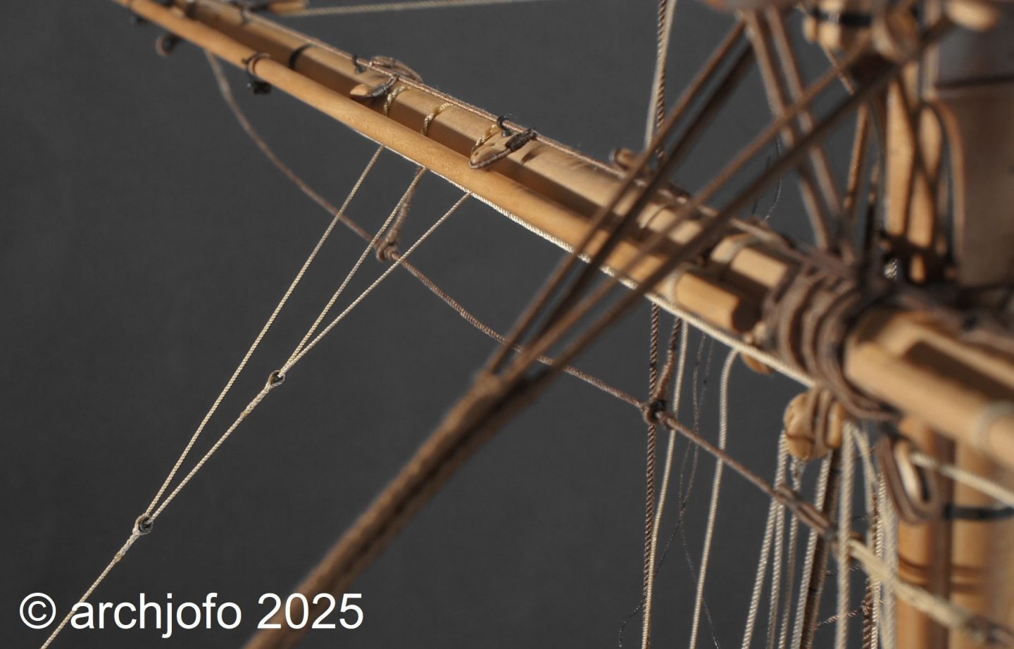
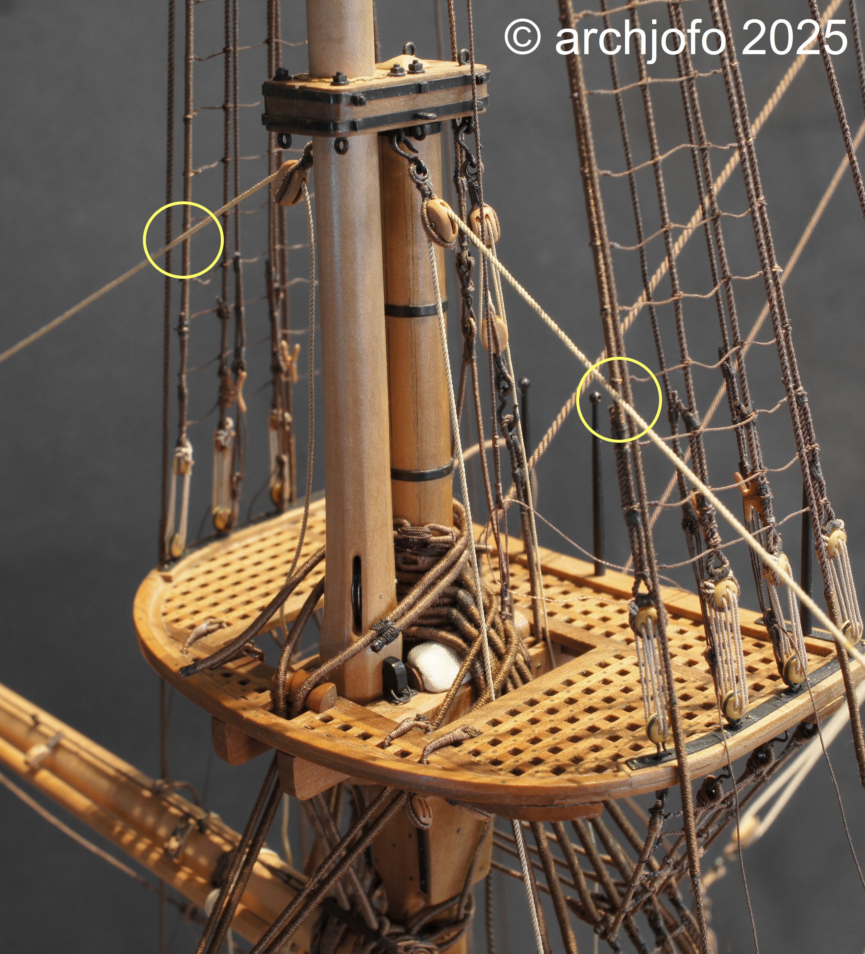
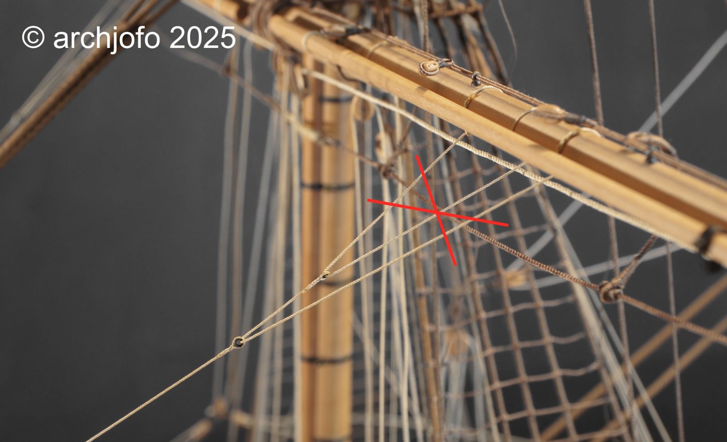
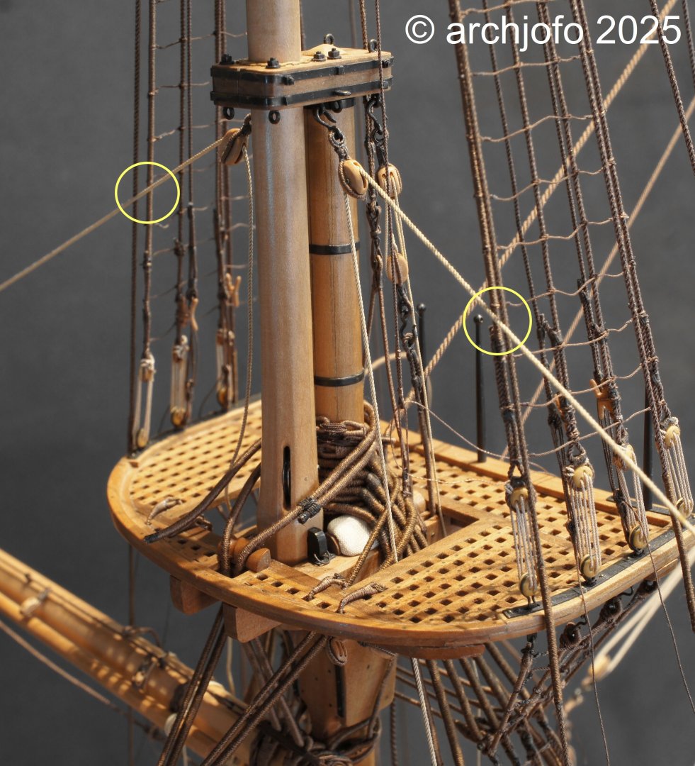
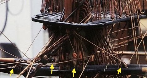
There's not much model building going on at the moment. Summer, house building for juniors, gardening, and so on... So here's a quick summer lull filler😁 Note on the routing of the lower yard lifts The following topic will be familiar to many experienced model builders who have already rigged a historic sailing ship, and it’s been discussed in this forum before. On my corvette, the same phenomenon appeared when belaying the lifts of the unbraced foreyard, as shown in the photo below: The lifts lightly touch the forward topmast shrouds. Since this might unsettle some beginners, I’ll briefly summarize why this happens. Lifts are usually led from the center of the mast cap -i.e. behind the topmast- out to the yard arms. The foreyard hangs in front of the lower mast, and so lies beneath the topmast. In side view, the forward topmast shrouds run verticaly up from the lower mast to the topmast head. Because of this geometry, the lower yard lifts inevitably come into contact with the forward topmast shrouds even when the yard is unbraced, and certainly when it’s braced in. Accordingly, the forward topmast shrouds are always served against chafe. This is not an error; it’s simply a result of the rigging’s geometry and layout.
-
@Richard Braithwaite @shipman @dvm27 Hello Greg, Hello colleagues, I deliberately chose silk yarn as the raw material for the La Creole ropes, knowing that it wouldn't be very durable in the long run. However, the decisive factor for me was the look of the ropes, and that convinced me. What counts is the here and now. What happens to the model after me is beyond my control anyway.
-
@Richard Braithwaite Hello Richard, Thank you for your interest and the nice comment. I made the ropes myself from silk yarn on my rope walk.
-
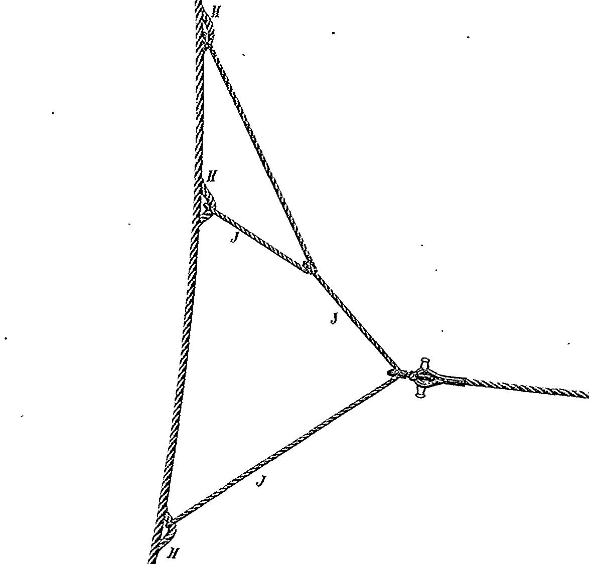
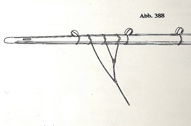
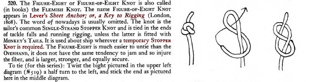
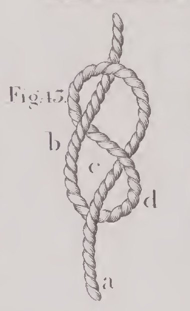
Continuation: Fore yard – Leech lines and bunt lines / Cargo-fonds et cargo-boulines I'm still wondering how the leech and bunt lines were secured without sails to prevent them from slipping off the blocks. After further research, I've now come across a stopper knot called the figure-eight knot (French: Noeud de huit). This seems to be the ultimate stopper knot, especially well-suited for temporarily tying lines, such as leech and bunt lines without sails. When attaching the sails, it can be easily untied, even when attached to a block. It's stronger than a bowline and easier to control. This is also how it is described in principle in "The Ashley Book of Knots" with reference to the Lever's Sheet Anchor, as the following excerpts show. Source: The Ashley Book of Knots Source: The young sea officer's sheet anchor; Darcey Lever, 1813 The French call this knot a "noeud de huit." Once again, as so often with specific, detailed questions, G. Delacroix provided me with expert support. When I asked about the figure-eight knot in connection with leech and bunt lines, he told me that these knots are generally referred to as "stopper knots" in historical descriptions, and he could imagine that the figure-eight knot would have been quite suitable for this purpose and that its use is not uncommon. As for L'Egyptienne 1799, the loop-shaped knots should be viewed with skepticism, as the rigging is likely questionable in terms of restoration. In summary, I have come to the conclusion that I consider the figure-eight knot to be a completely historically credible variant for my model and will implement it accordingly. To be continued...
-
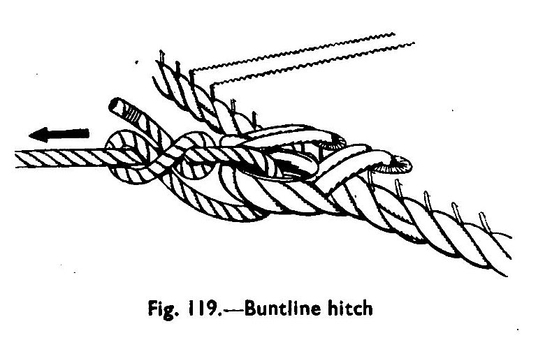
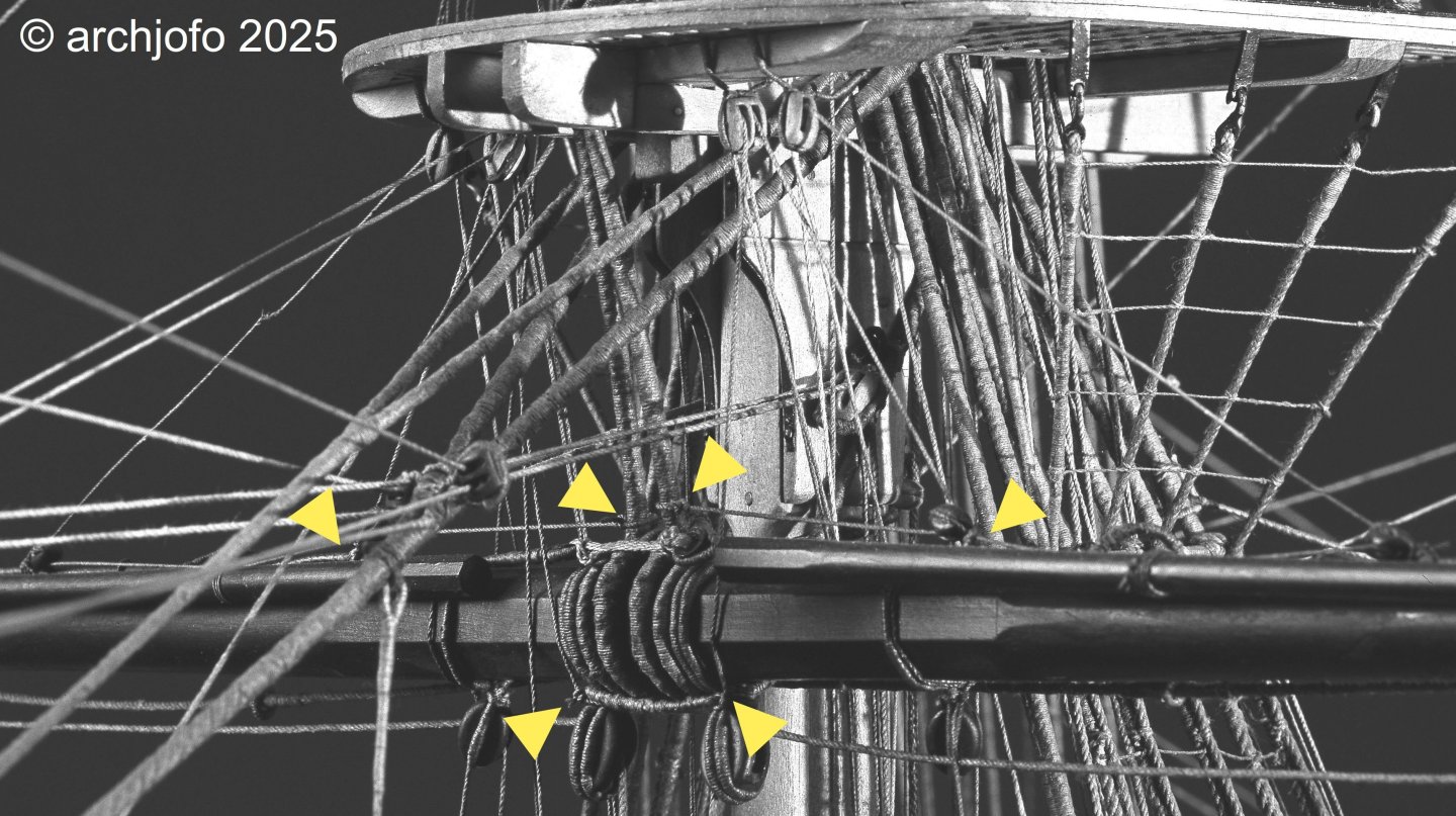
Continuation: Fore yard – Leech lines and bunt lines / Cargue-fonds et cargue-boulines Among other things, I am currently preparing to attach the leech lines and bunt lines to the fore yard. The corresponding blocks are already in place both on the yard and in the form of guide blocks under the fore top. Since I am rigging my model without sails, these ropes must be secured against slipping from the corresponding blocks. Knots have been tied to the lines for this purpose, as seen on many models, including contemporary ones. However, what I have also occasionally seen in illustrations of these on models from the Musée de la Marine in Paris are loop-shaped knots, presumably buntline hitches, but could also be bowline knots or similar. The leech lines and bunt lines are then securely attached to the corresponding cringles of the sail using buntline hitches. Source: Manual of Seamanship, Vol. 1, 1951 In any case, a knot that can be easily untied when the sails are hoisted back up. Here, using the example of L'Egyptienne from 1799, the "loops" are clearly visible upon closer inspection. Source: Image detail from the original model of L'Egyptienne 1799 in the Musée de la Marine in Paris A third way to secure the bunt lines against slipping out of the blocks would be to simply tie the ropes, as can be seen on the original Paris model of La Créole. Source: Image detail from the original model of La Créole in the Musée de la Marine in Paris Three possibilities, which naturally raise the question of which one is closest to historical reality. Therefore, I would be very grateful if you could share your expertise with me. I look forward to your contributions.
-
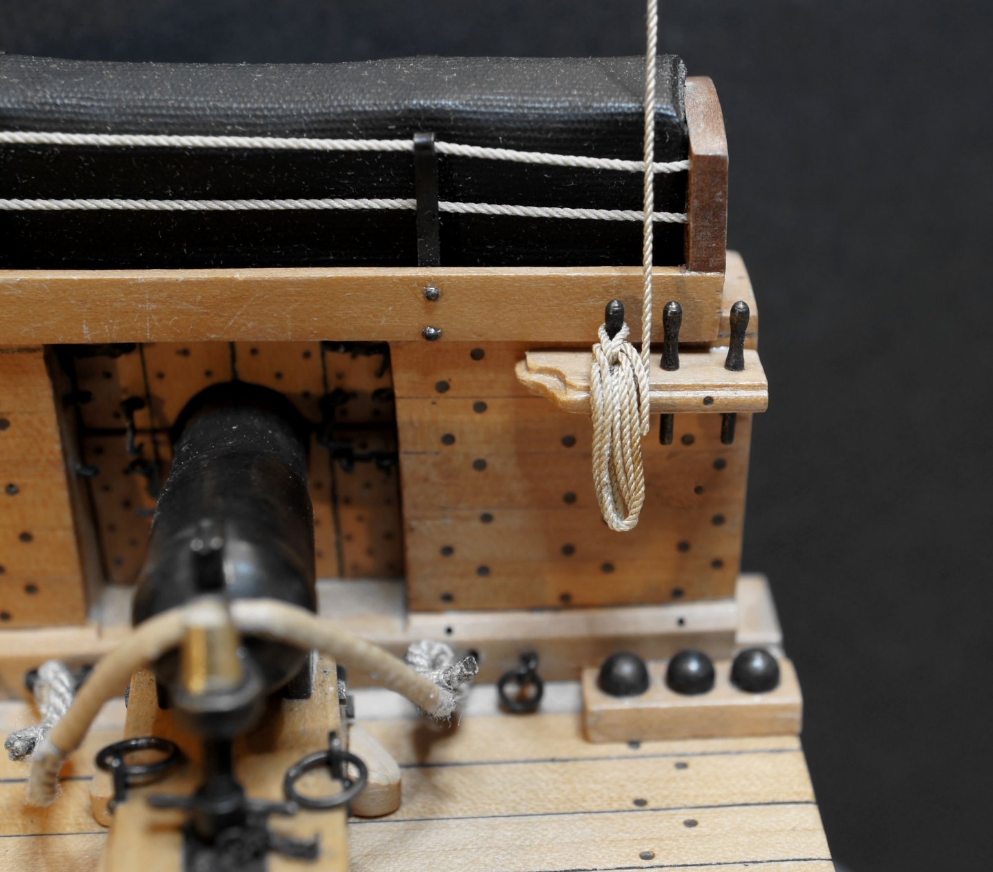
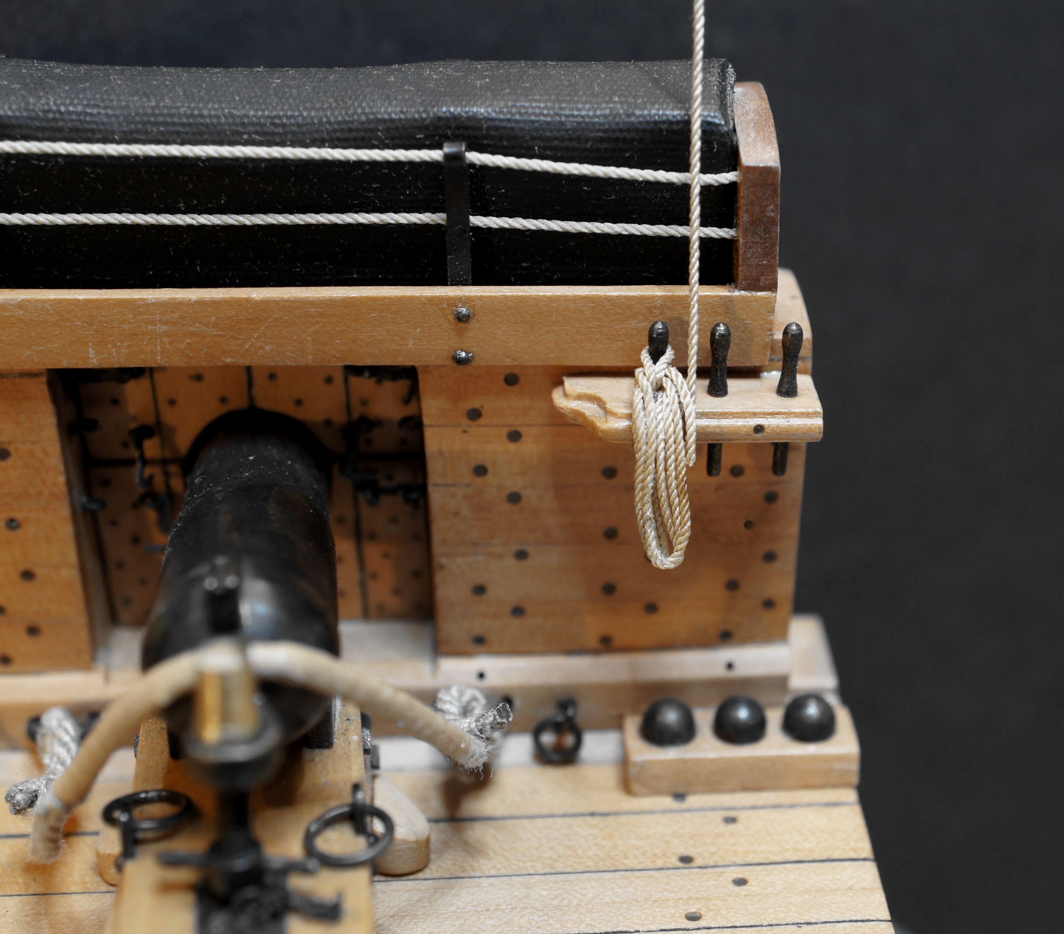
@shipman @SaltyScot Hello, Thank you very much for the nice comments. I'm very happy. Thanks also to everyone else for the many likes. Continuation: Fore yard – Bowlines / Boulines I've also since read up on the arrangement of the bowline bridles in the contemporary specialist literature "Manuel de Greement" by F. A. Coste from 1829, starting on page 167, and it fits. The only thing is that it refers to thimbles through which the individual rope limbs are threaded. I also looked again in Marquardt, which also covers the rigging of French ships, although again only up to the end of the 18th century. If I now incorporate the aforementioned contemporary illustrations from the early 19th century and models from the Paris Museum into my considerations, I come to the conclusion that the bowline bridles on my corvette could well have looked the way I have since attached them to the fore yard. I can't clearly verify the attachment of the bowlines without sails for the French, as shown in the K. Schrage's book – Rundhölzer, Tauwerk und Segel – . But I think it's quite realistic that the French did it the same way as the British. I'm currently building a jig to make rope coils for the belaying pins. I imagine it might look like this: More on that soon...