HOLIDAY DONATION DRIVE - SUPPORT MSW - DO YOUR PART TO KEEP THIS GREAT FORUM GOING! (Only 20 donations so far - C'mon guys!)
×

archjofo
-
Posts
1,495 -
Joined
-
Last visited
Content Type
Profiles
Forums
Gallery
Events
Everything posted by archjofo
-
 @matiz Your stove has become a small work of art. And the preparatory work for the gun carriages again promises very nice guns. I'm really looking forward to that.
 -
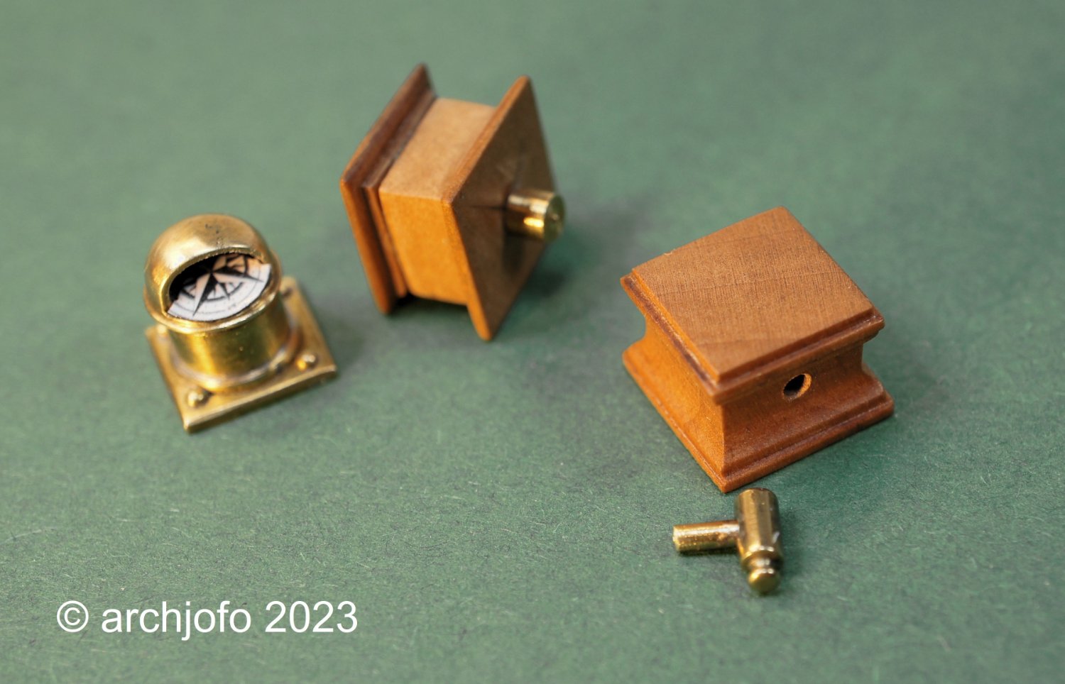
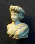
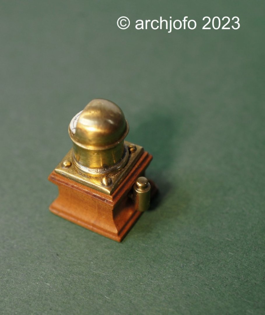
Continued: ship's compass Some time ago I was concerned with the question of what the part at the back of the binnacle of the La Créole is. There is much to be said for a soft iron corrector, the so-called flinders bar. Lighting would also be conceivable based on the shape. The discussion, including in the MSW, does not yield a clear result. After I got to see historical compass housings in the meantime, where the lighting was arranged below the compass rose, I personally tend to think that this could have been a lamp. Also because of the fact that this corvette was a wooden ship, i.e. had little iron to influence the compass, and on the other hand lighting seems to be quite useful and necessary. In the end I can't say for sure. So I decided to just build this thing and leave it up to the viewer what he thinks it is. On this occasion I revised the compass and remade the wooden case. The lamp ? or the soft iron corrector? was made from a round brass rod ø 1.5 mm analogous to the photos of the Paris model available to me. Sequel follows …

-
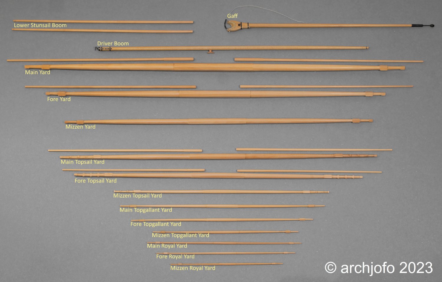
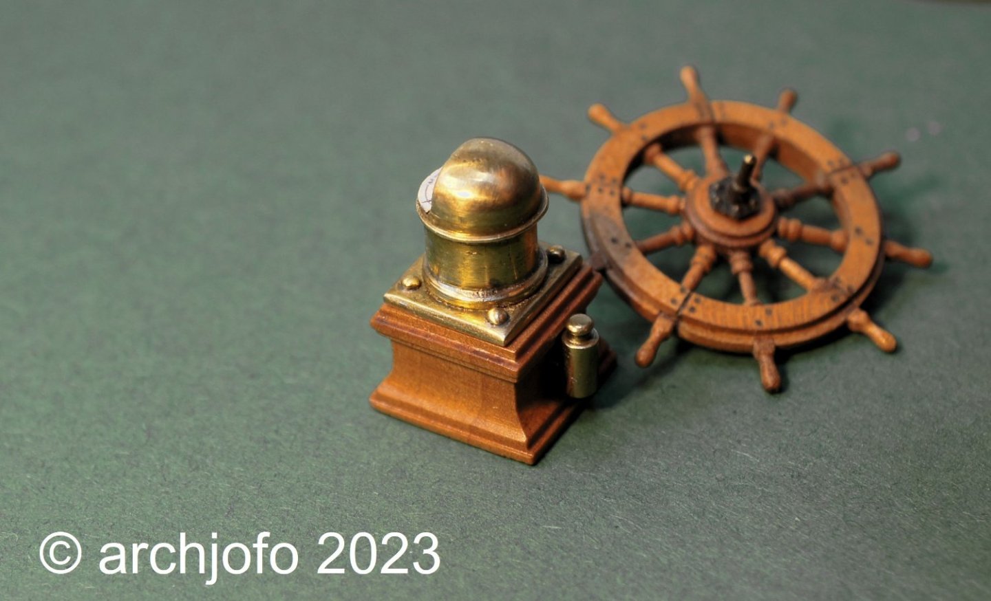
@jdbondy Hello, I sand the surface of the spars with 500 grit sandpaper and finish with a fine steel wool. Completion: Yards and spars With the production of the lower studding sail booms, which are attached to the fore-channels, I could finish the chapter yards/spars for my corvette. So I had to show all the spars in their entirety, as you can see below: This completes the woodwork on this model except for more blocks and a few odds and ends. I am currently researching the studding sail boom iron, among other things. Also for this there is a multiplicity of variants, which are to be evaluated and classified chronologically correctly. The monograph of J. Boudriot leaves some questions open. See you soon ...
-
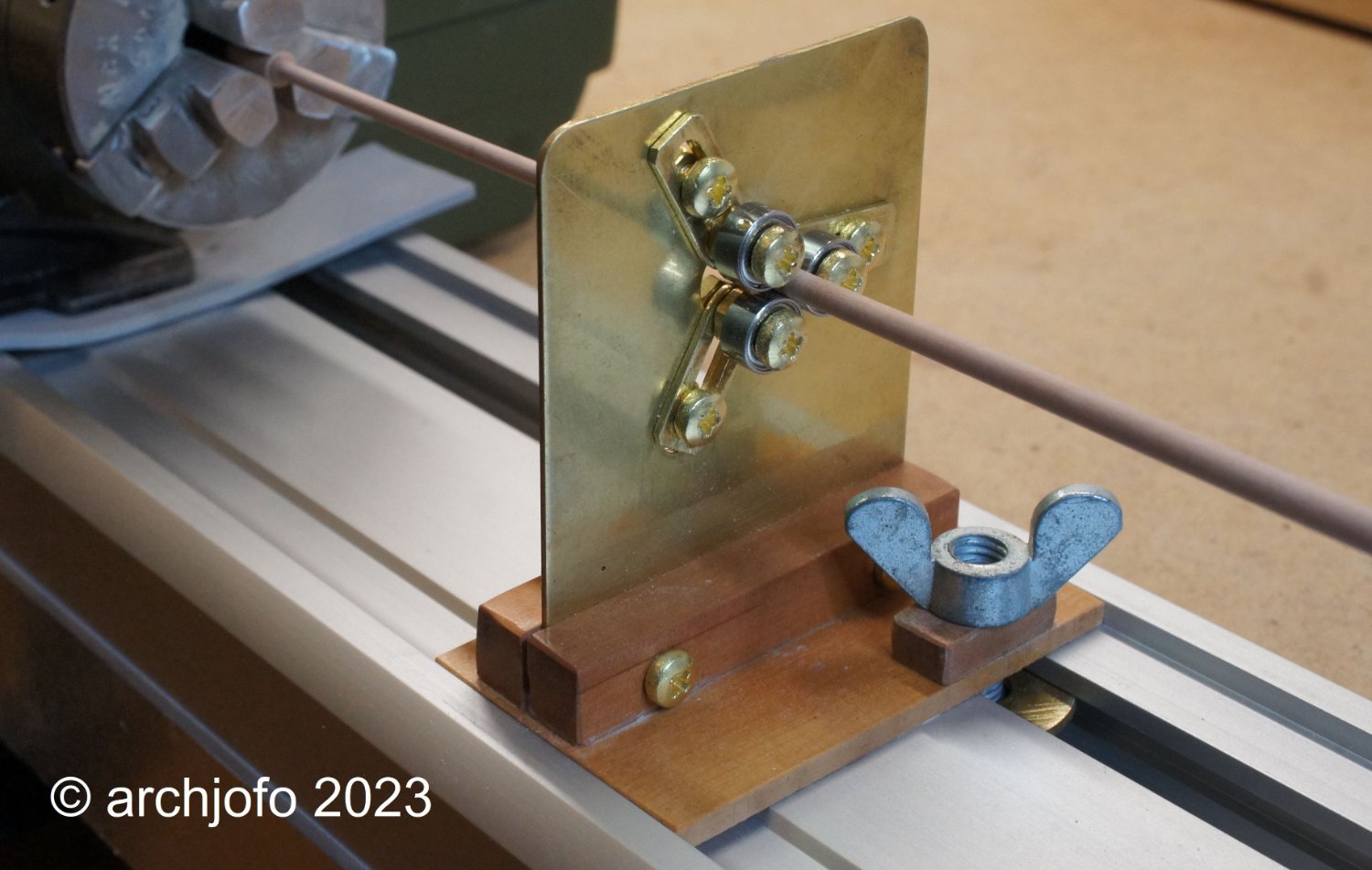
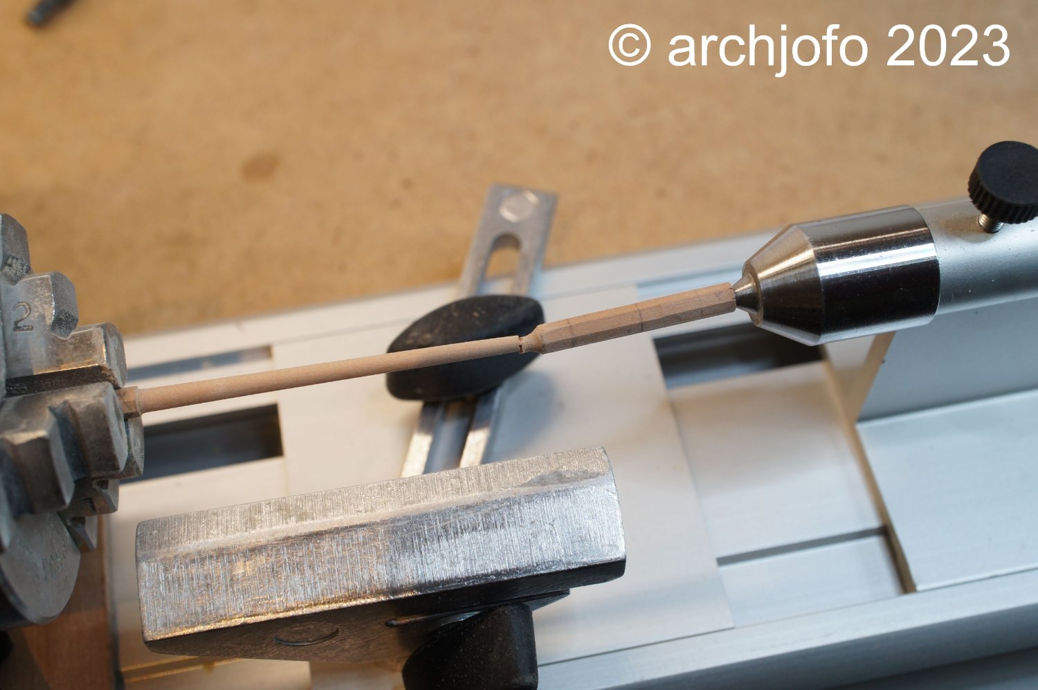
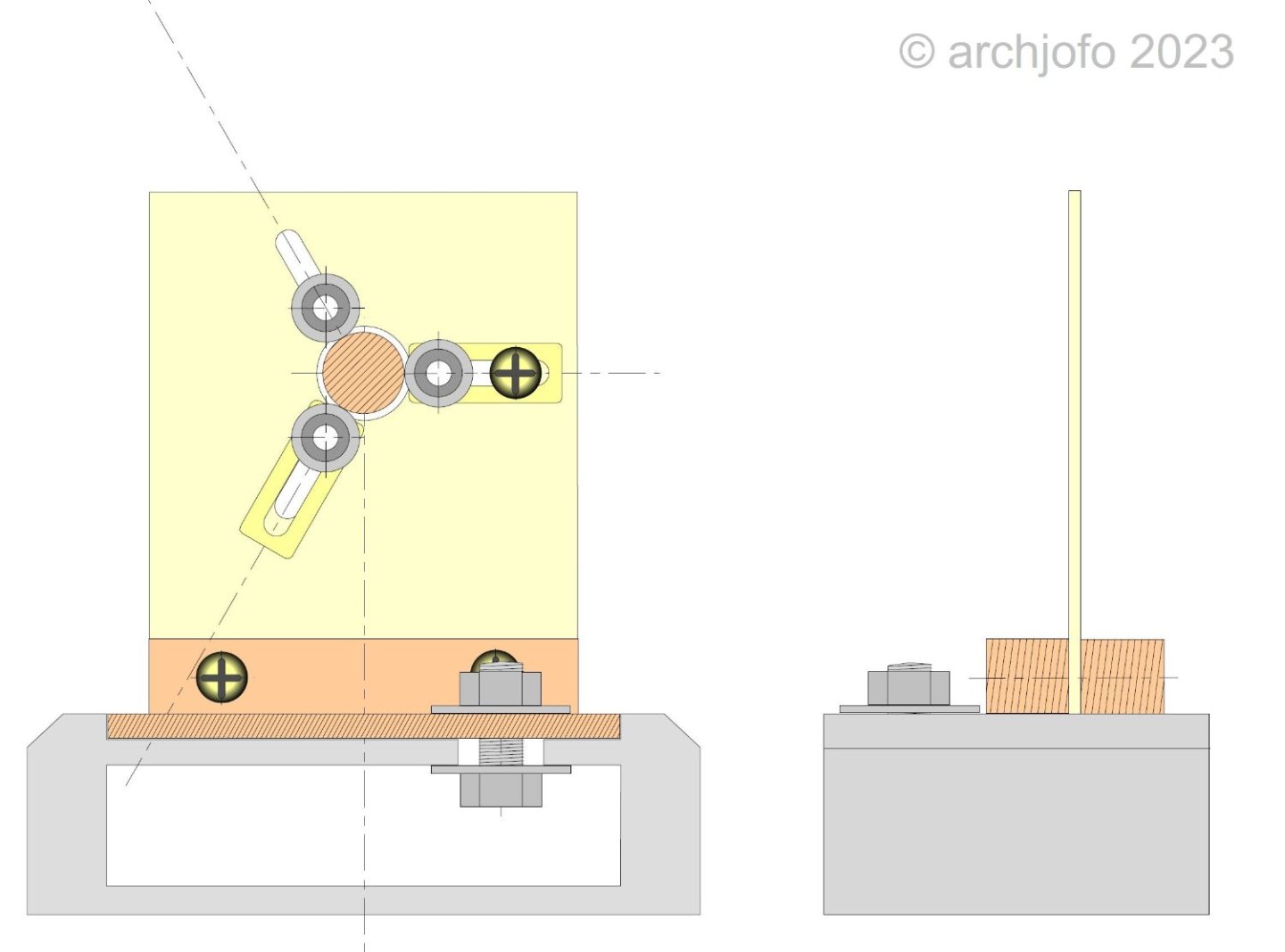
@shipman This steady rest I have built with simple means. With this I can position small ball bearings for round logs with diameters of 1 - 10 mm for support. The simple tool has already proven itself very well.

-
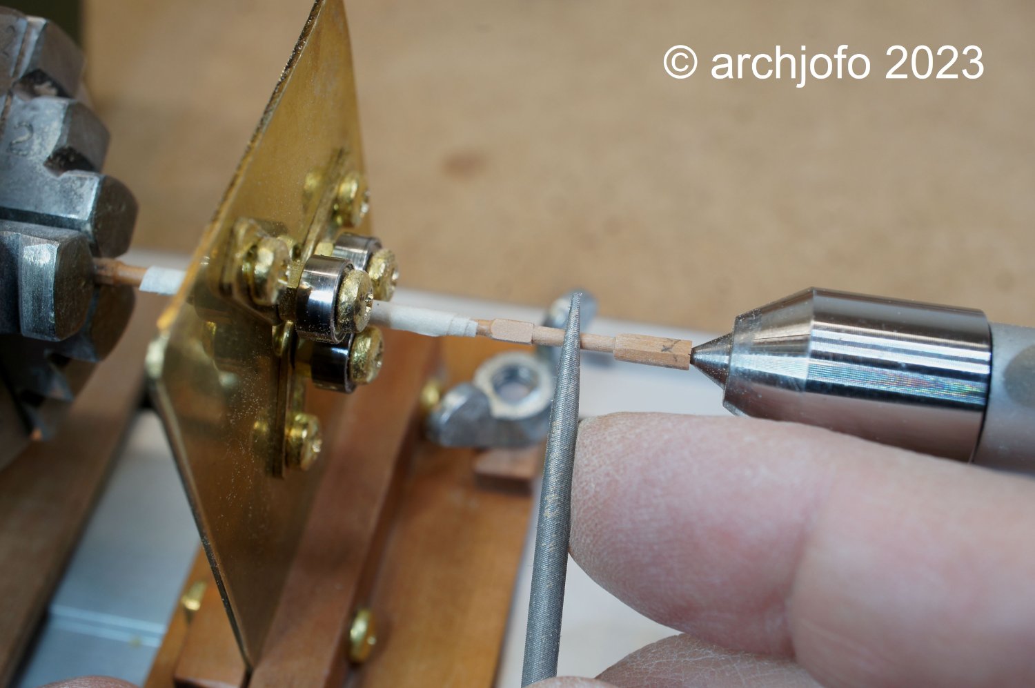
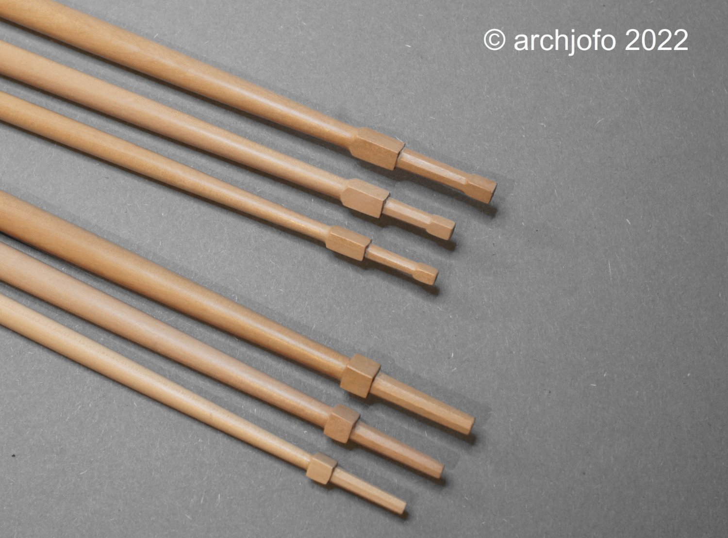
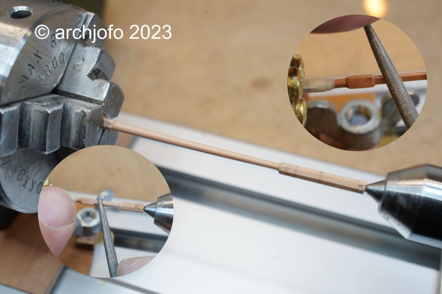
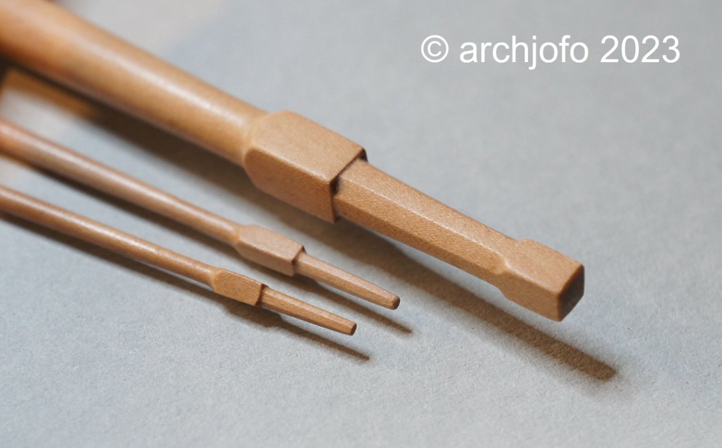
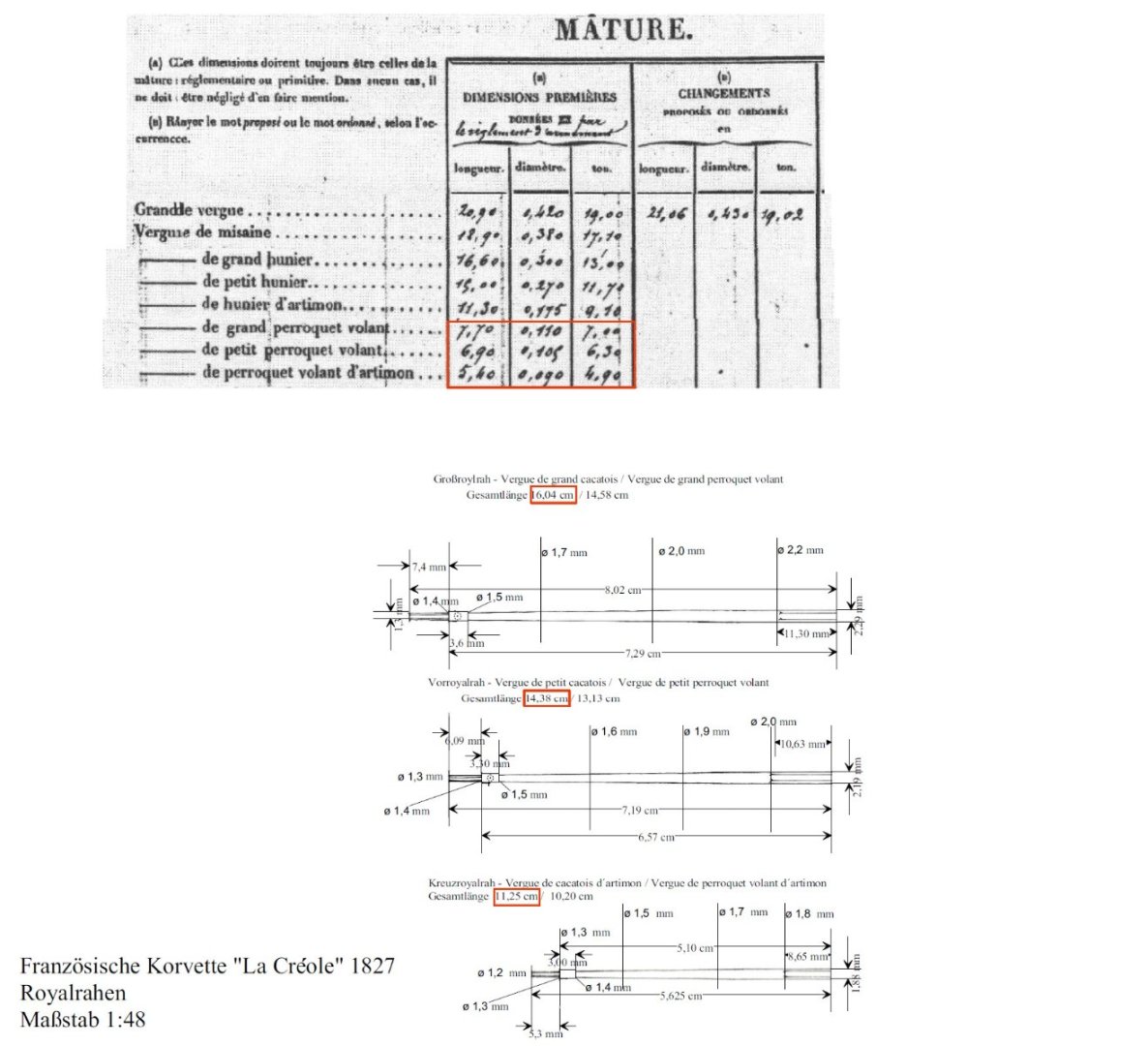
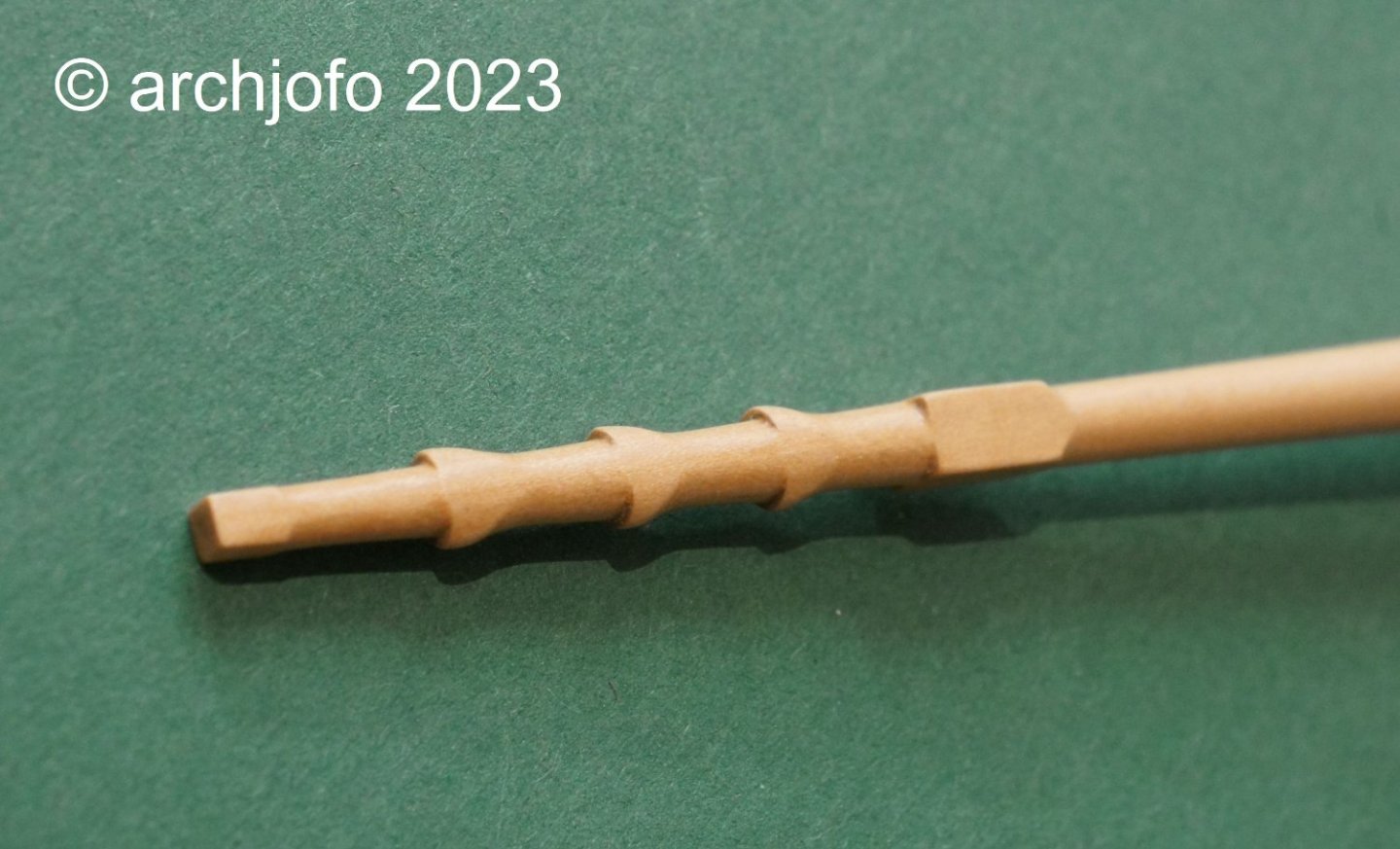
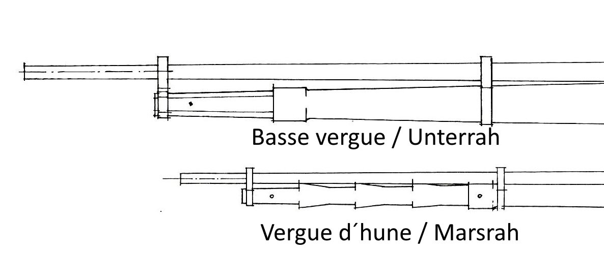
@Nunnehi (Don) @matiz Hello, thank you for the interest and the good comments, and thank you also the others for the many LIKES. Continuation: Making the topgallant yards - Vergue de cacatois In the meantime, I have started making the topgallant yards. As already written in the last report, the topgallant yards are even thinner and more filigree, like the topsail yards. The dimensions from the plan documents of J. Boudriot were again compared by me with the data of a contemporary original document. This table shows the dimensions of the masts and yards of the La Blonde, which is identical in construction to the La Créole. All dimensions corresponded to the drawings, as is clearly shown in the following drawing. I have already noted that with these dimensions at ø 1.4 mm it is no longer feasible without a steady rest. A toothpick, for example, has a diameter of 1.8 mm. In this respect, particular care should be taken here and not too much pressure should be exerted on the roundwood. The shaping of the square edge with the octagonal yardarm also requires sensitive processing, which can be seen in the next picture. At the end of this work, a comparison of yardarms: Main yard, mizzen toppsail yard and mizzen topgallant yard Now two lower studding sail booms have to be made to hang on the fore channels. With the gaff (upper spar) and the driver boom (lower boom) already made some time ago, all the sail-carrying spars for the French corvette are then ready. They will then be equipped with the necessary fittings (sheaves, boom irons, etc.). To be continued ...

-
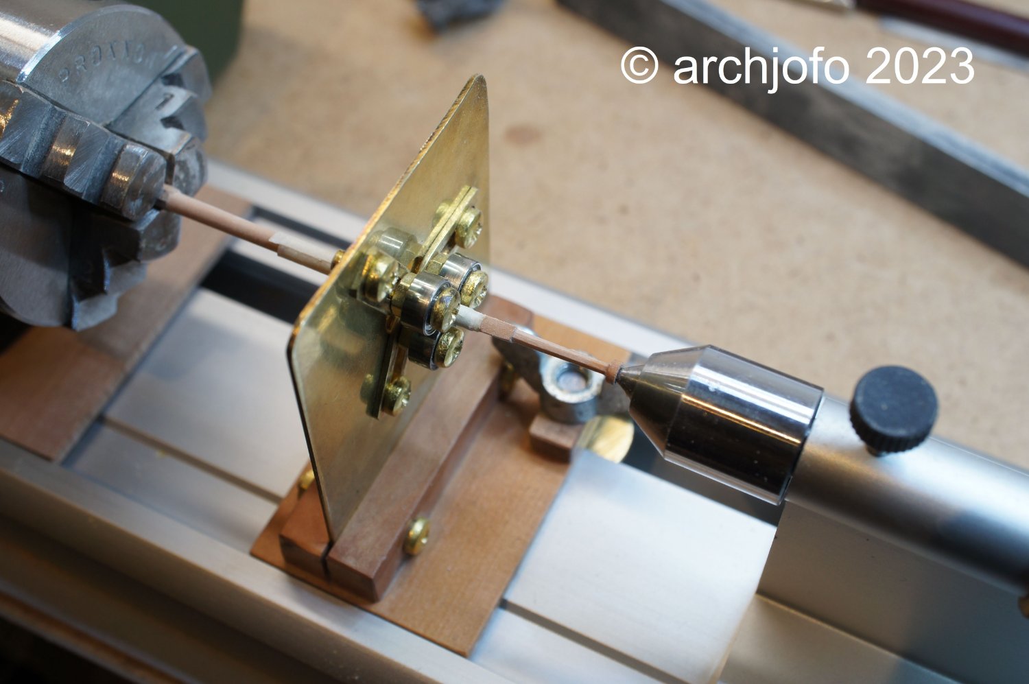
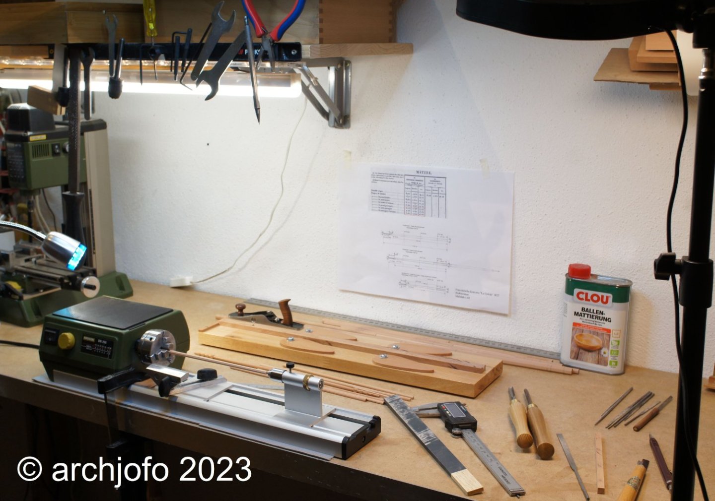
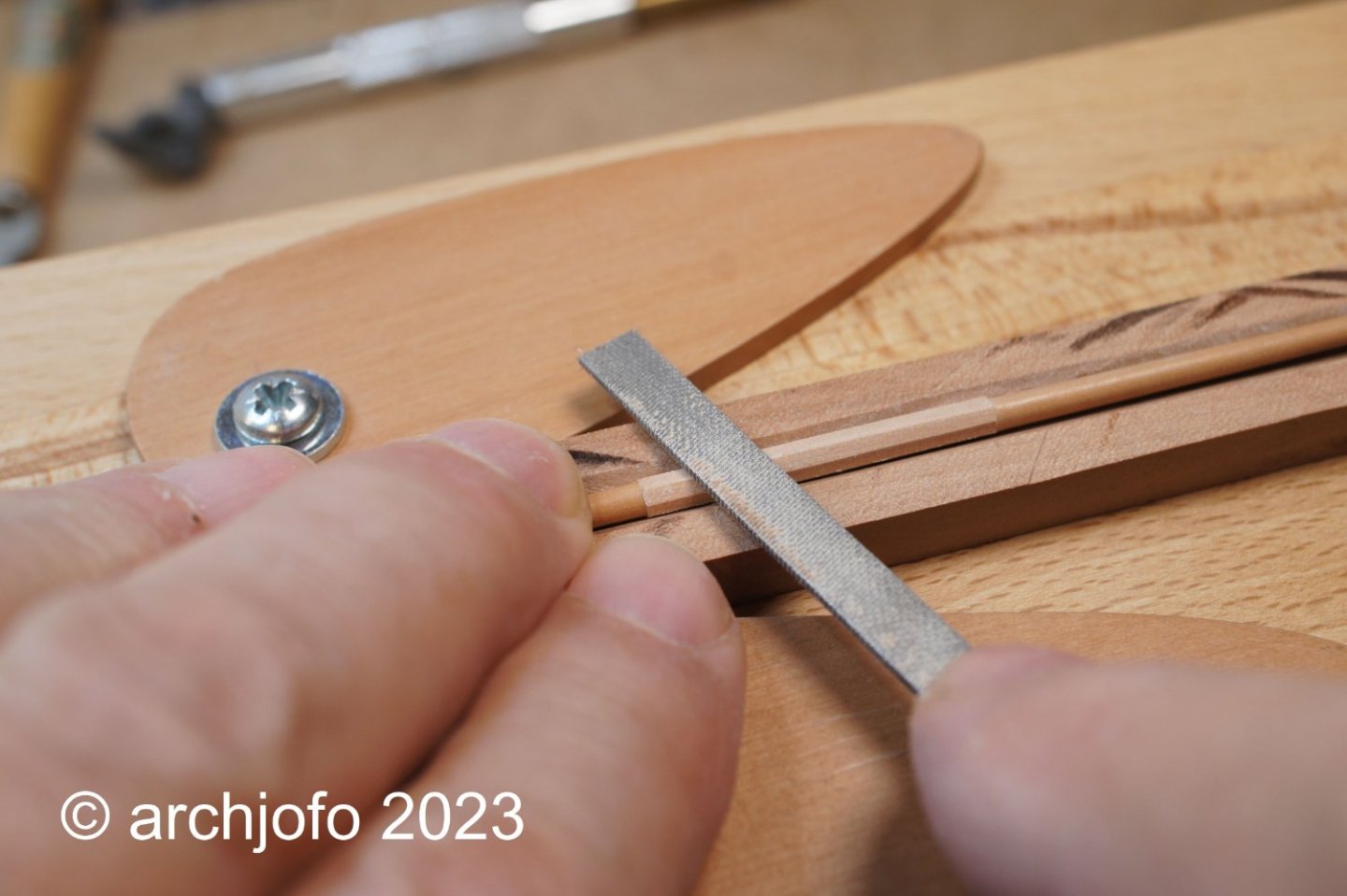
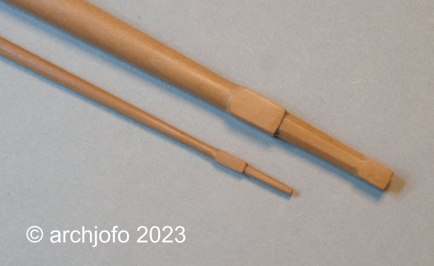
Continuation: Making the yards - Topgallant yards - Vergue de perroquet After the topsail yards, we continued with the making of the topgallant yards. Here is a quick look at my workplace with the most important utensils for making the yards: The diameters of the topgallant yards, especially in the outer sections, range around 1.6 mm. In this respect, it is not surprising, if you work without a steady rest, that it can sometimes come to breakage. At the latest when working on the yardarms, it is advisable to support the filigree yards with a steady rest. The next picture shows the finishing of the octagon in the center of the yard. The last picture should give an impression of how filigree the topgallant yards are compared to the lower yards. It shows the yardarms of the main yard compared to the mizzen topgallant yard. The octagon of the yardarm of the mizzen topgallant yard still has a width of 1.3 mm at the outer end. Of course, the royal yards can be made even thinner and more filigree. Especially the octagonal shaping at the yardarms requires special care. To be continued ...


-
Hello Siggi, Thanks for the pictures. It looks as if this is a lamp that is placed below the wind rose. Accordingly, Keith's ( @Keith Black ) reasoning would be absolutely correct.
-
Maybe the compass question can still be solved, in the meantime things will continue with the yards: Continued: Making the yards - main topsail yard - Vergue de grand hunier For long enough I evaded the decision to execute the yardarms of the main topsail yard. Further research on this did not bring any new findings. Now that the holidays are over and with renewed vigor in the new year, I have decided on the following embodiment of the yardarms of the topsail yards, as already signaled in one of the last posts: So now we can continue with the production of the yards. Sequel follows …
-
Hello Keith, this question is quite justified, and of course I have already asked myself. So I looked for examples where a lamp is attached to the bottom of the case. Like Bob, I reasoned that this is how the light shines from below between the hanger and the compass card. But like I said before, I couldn't find anything about it. In the end I don't know.
-
Hello Bob, I have also considered this possibility and searched for examples on the Internet. After I have found no similar cases, I have discarded these thoughts. There seems to be a lot to be argued for a flinders bar.
-
Hello fellow colleagues, Thank you for your interesting contributions. Andy's explanation (@realworkingsailor) meanwhile I also think it's very plausible. Thank you for this post too.
-
It's an interesting approach, let's see. Isn't it too far down for a lamp?
-
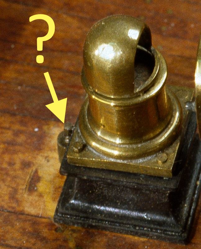
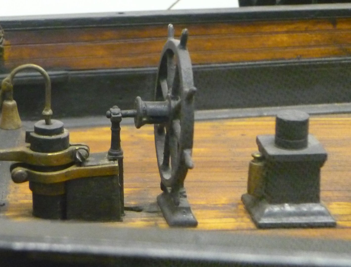
Hello fellow colleagues, happy new year 2023, and above all health. Before we continue with the yards with fresh energy and motivation, I would like to clarify one more question about the ship's compass. ship compass There is a cylindrical part on the back of the La Créole compass housing, which I recently discovered in one of the high-resolution images from the Musée national de Marine Paris. Source: Musée national de Marine Paris This part can be seen even better on a photograph of the steering gear of a contemporary model from the Paris Museum (compass is unfortunately missing). Source: Musée national de Marine Paris I would like to add this part to my model and find out more about its function. Based on what I've learned so far, I see two possibilities: - It could be a so-called flinders bar (soft iron corrector), which reduces the influence of the compass needle on iron parts; - or to a lighting. However, the fact that it is a wooden ship speaks against the flinders bar. Only the guns could have a corresponding impact on the compass needle. Basically, these brass binnacles of the compasses were illuminated with oil lamps, which were also cylindrical and designed with a round attachment (ventilation). From what I saw on the internet, for example, these cylindrical parts were located directly on top of the housing and were usually attached on both sides. Therefore, I see this part in its function as a soft iron corrector, or is there another explanation? I would be very grateful for your help with this. It would be nice if I could get more information on this.
-
Very nice work !
-
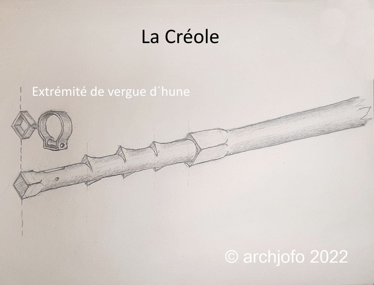
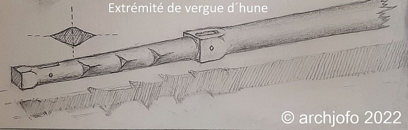
Continuation: Clarification of the yardarms As already announced, I have now also drawn a variant with vertical cleats. However, with this variant I see a big problem with the guidance of the topgallant sheets. In addition, I find on the contemporary ship models actually predominantly horizontally arranged cleats. The pictures of the La Créole, which were kindly given to me by the Musée national de Marine Paris, do not show the decisive details of these filigree parts in spite of a higher resolution. But in connection with the already shown yardarm of the Le Suffren I will most likely realize the previously drawn variant. The yardarm of the Le Friedland 1810 also goes in this same direction. During all the research I also found out that the yardarms of the lower yards so far are not quite correct, so I simply made these yards (shown in the picture above) again, as shown below: To be continued ...

-
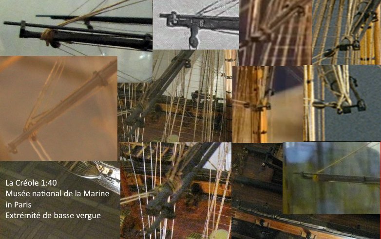
Hello Gerard, Thank you very much, that is a very big help, especially the chronological classification. This gives me confidence in my decision to bring the studding sail boom irons directly in front of the yards. I recently received higher resolution images from La Créole from the Musée national de Marine Paris. You can see the details of the yardarms a little better there. But only so far that you can see that the studding sail boom irons do not have a 45 ° angle, but place the studding sail boom directly in front of the yards. Here I show a compilation of the lower yard arms of La Créole in the form of excerpts from the image material available to me. Source: Musée national de Marine Paris
-
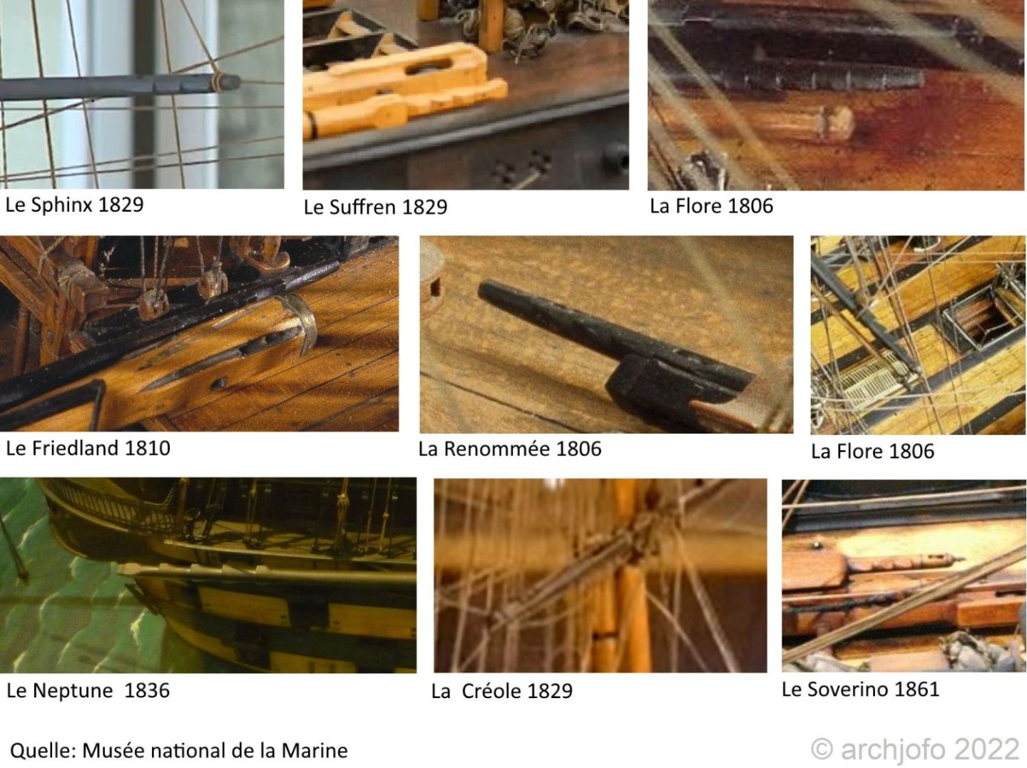
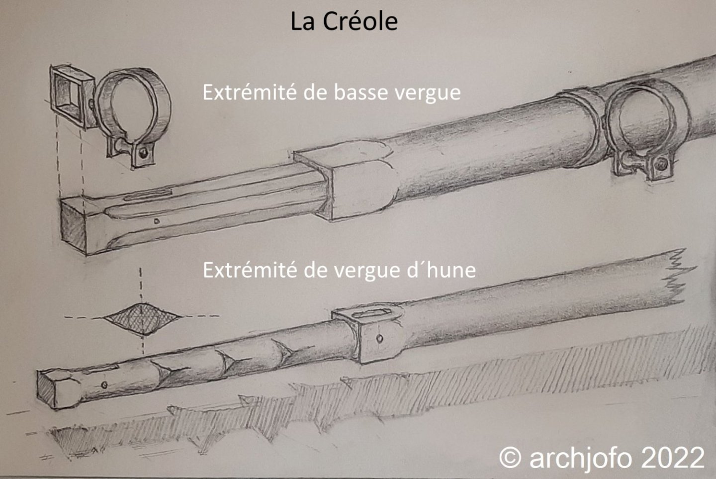
Hello, many thanks to you for your interest and your contributions, as well as thanks to the many LIKES. Continued: Clarifying the yard arms After researching contemporary ship models from the Musée national de Marine, I assembled a collection of yard arms as shown below: As you can see, there were the most diverse forms of yardarms, probably also depending on the shipyard in which these yards were manufactured. But they all have the "spiky" cleats, which do not always stick out vertically, but often horizontally and are mainly to be found on the topsail yards. The yard arms of the lower yards were somewhat simpler and often designed like the following example from L'Achille 1804: Source: Musée national de Marine, L'Achille 1804 Source: monograph La Créole v. J Boudriot Taking into account the results of the research in connection with Boudriot's drawings, I tried, initially in drawing, to represent the yards of the Mars yards of La Créole as they might have looked. In particular, I orientated myself on the yard arm of the yard on the model of the Le Suffren 1829. Not only does the period fit, the Le Suffren was also designed by the naval architect P. M. Leroux, like the La Créole. Therefore, I see my subsequent attempt at reconstruction as a thoroughly realistic variant. The cleats may also have been vertical. In this respect, I will also draw a variant and then make a decision. Sequel follows …
-
Hello Gerard, no problem. Discussion was factual, and was not uninteresting. Now back to the real problems of the world ... to the yard arms of La Creole ... 😁
-
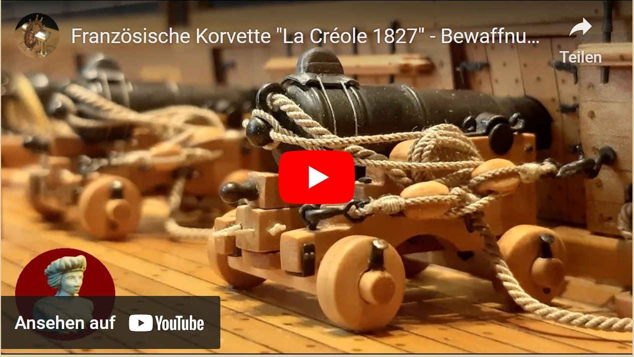
Hello, in between I made a video about the naval artillery of my french corvette. I tried to show the different stages of construction. I hope that one or the other likes it and perhaps serves as inspiration. Have fun ! LINK
-
@John Fox III @Keith Black @JerryTodd @wefalck Your posts on this topic are really very interesting. Ultimately, I will make my conclusions about the details of the yard arms from all the information I have been given, visual material from the Internet and from contemporary literature. I hope that this will result in a viable design for my model.
-
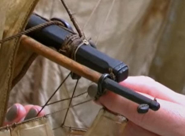
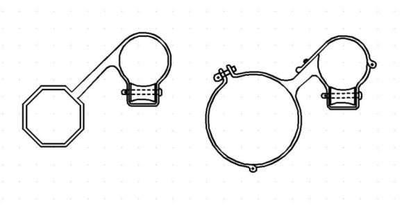
At LA CRÉOLE the stun'sail boom irons probably looked like this:
-
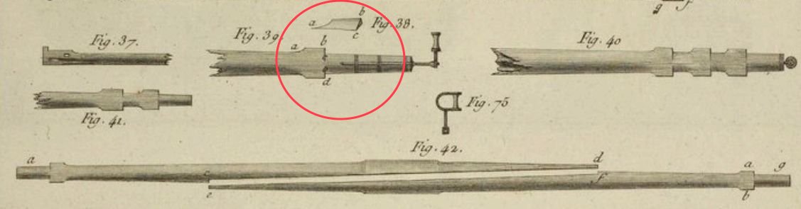
Continued: Clarifying the yardarms After an extensive web search I came across this book: "Description de l'art de la Mâture" (published in 1778) by Charles Nicolas Romme. Below are excerpts of the yardarms: Fig. 38 clearly explains the "oval" cross-sections in the area of the cleats on the yardarms. In connection with the design of the yardarms for the La Créole, the question of the chronological classification naturally arises: The Le Rivoli is from 1810, the Le Sphinx from 1829 and the Le Neptune from 1836. In this respect, this is for the epoch of the La Créole applicable. Apparently I'm not the only one who stumbled across this problem. So thanks again to G. Delacroix who gave me the crucial hint. For my model, however, the question now arises as to how I can reconcile this detail with the drawings by J. Boudriot. I would prefer to stick to the original model. Unfortunately I don't have any meaningful detailed pictures. Ultimately, I will have to make a decision about this detailed design, even with the risk that it will not be entirely correct.