HOLIDAY DONATION DRIVE - SUPPORT MSW - DO YOUR PART TO KEEP THIS GREAT FORUM GOING! (Only 20 donations so far - C'mon guys!)
×

archjofo
-
Posts
1,495 -
Joined
-
Last visited
Content Type
Profiles
Forums
Gallery
Events
Everything posted by archjofo
-
 @G. Delacroix Thank you in advance for the valuable information. I obviously misinterpreted the drawing by J. Boudriot. Now following your hint I see that it only works graphically as an oval. I also researched my picture collection again and found a picture of the Le Neptune 1836 from the Musée national de la Marine Paris. A yard can be seen there as a reserve, comparable to that of the Rivoli. Allowed me to include your drawing and that of J. Boudriot in this example. Source: Musée national de la Marine Paris, G. Delacroix, J. Boudriot I also found a very interesting picture of a yardarm from the mizzen topsail yard of Le Sphinx 1829. Source: Musée national de la Marine Paris Will now try to make the yardarms of the topsail yards for the La Créole in the oval version according to the drawing by J. Boudriot. I am very open and grateful for further hints and examples.
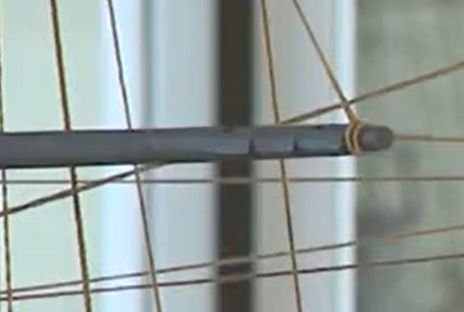
-
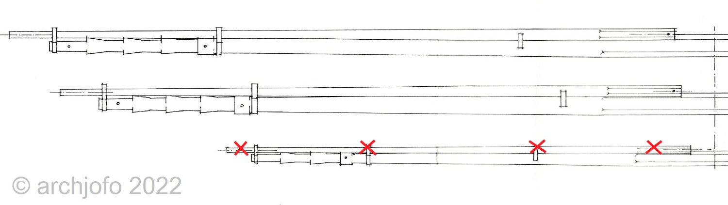
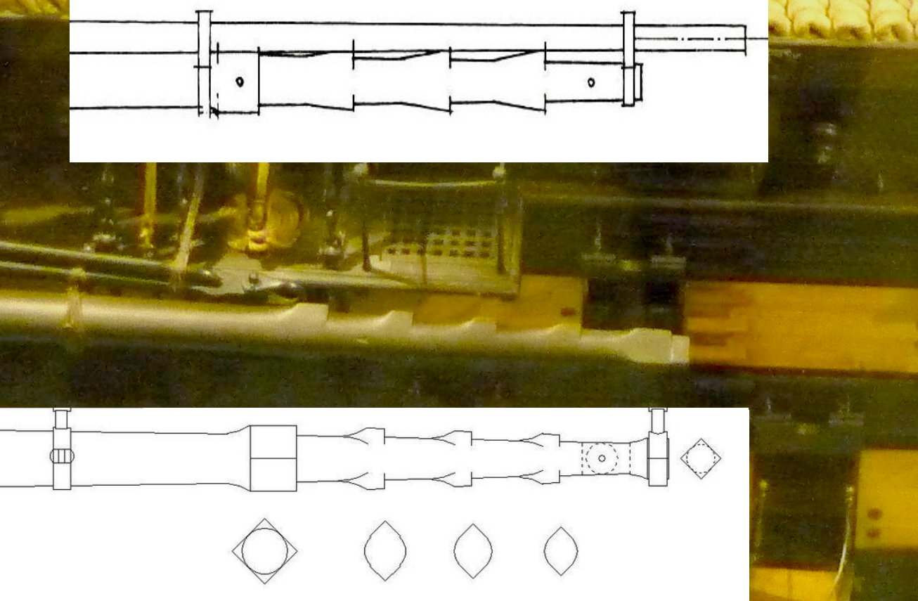
Continuation: Making the yards - Fore topsail yard - Vergue de petit hunier After making the lower yards, I started working on the topsail yards. In contrast to the yardarms of other navies in the comparable period, the ones of the French navy seem adventurous. Probably due to a higher flexibility of the sailing maneuvers, these topsails are a certain challenge for the modeler, as can be seen on the following pictures for the mizzen topsail -, fore topsail - and main topsail yard of the La Créole. Source: Monograph La Creole by J. Boudriot Unfortunately, I do not have sufficiently sharp images of the original model from which one could derive further details. So I rely on the plan drawing of the monograph except for the formation of the studding sail booms at the yards of the mizzen mast. For this I again follow the original model, which clearly shows no studding sail booms at the mizzen mast. Further research shows that many contemporary French models also do not have studding sail booms at the yards of the mizzen mast. John Harland in his book "Seamanship in the Age of Sail" writes about studding sails on the mizzen mast that in his opinion they were neither popular nor particularly practical. After several attempts, the fore topsail yard seems to have succeeded according to the drawing specifications, at least I am satisfied. The next picture shows the fore topsail yard compared to the main yard, where the yard arm has a simpler design. The drawing with dimensions for the main topsail yard is already available. Soon it will go further ...

-
Hello Giorgio, this will be a very nice model. Very good work so far.
- 21 replies
-
- 3
-

-
- Swift
- Artesania Latina
- (and 2 more)
-
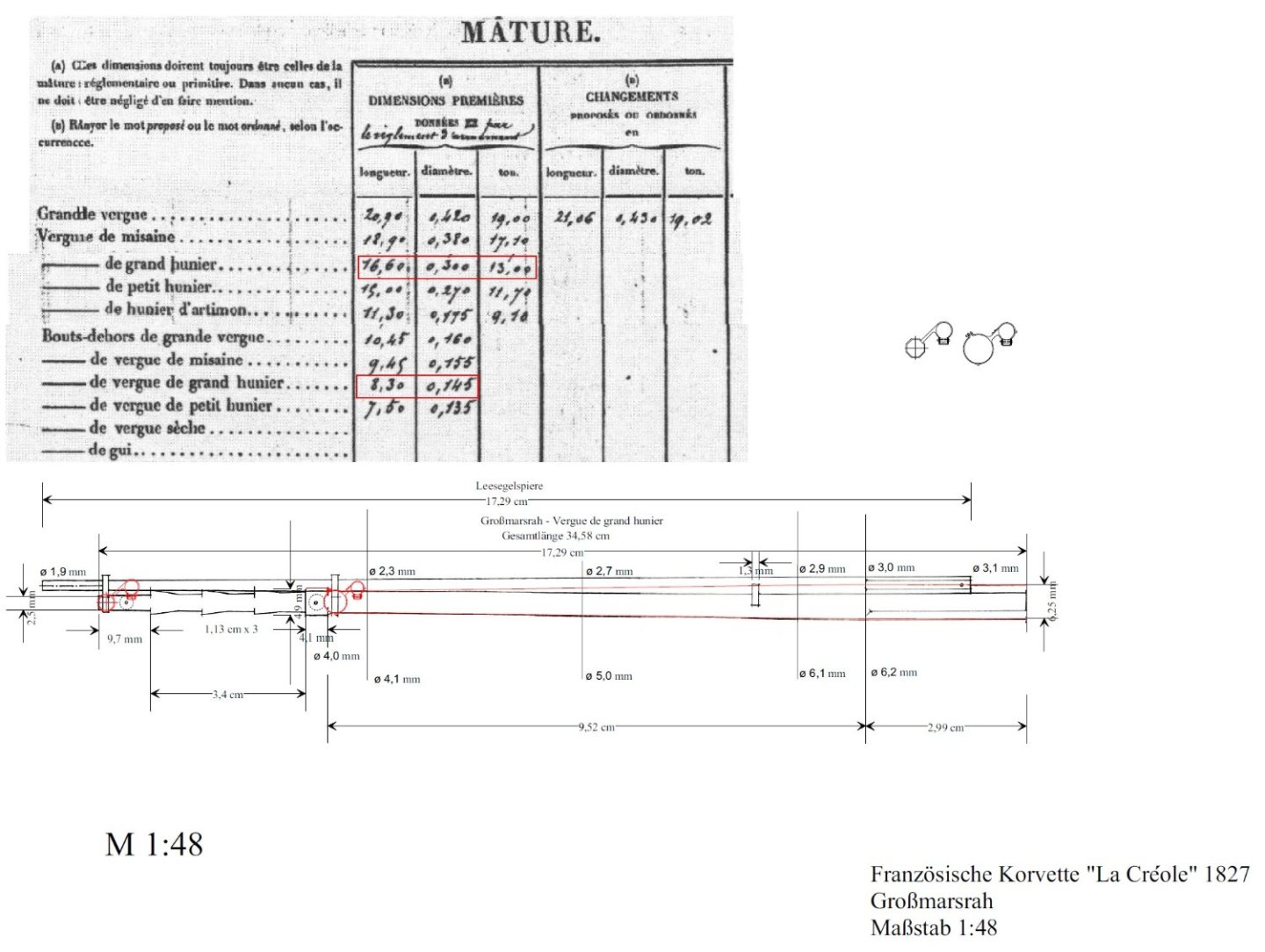
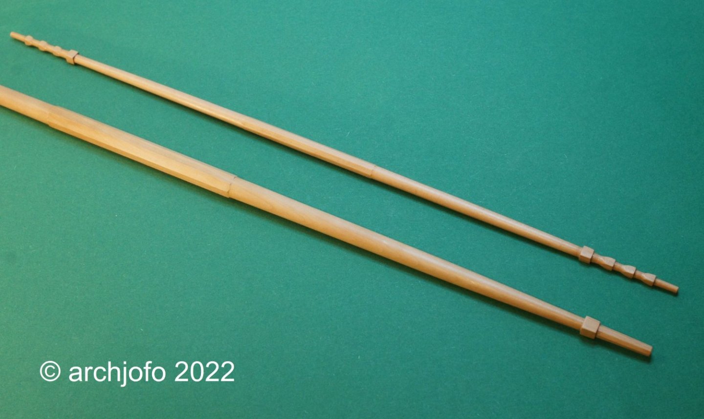
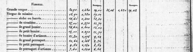
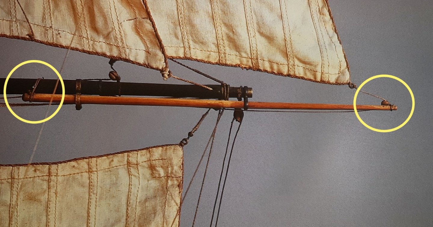
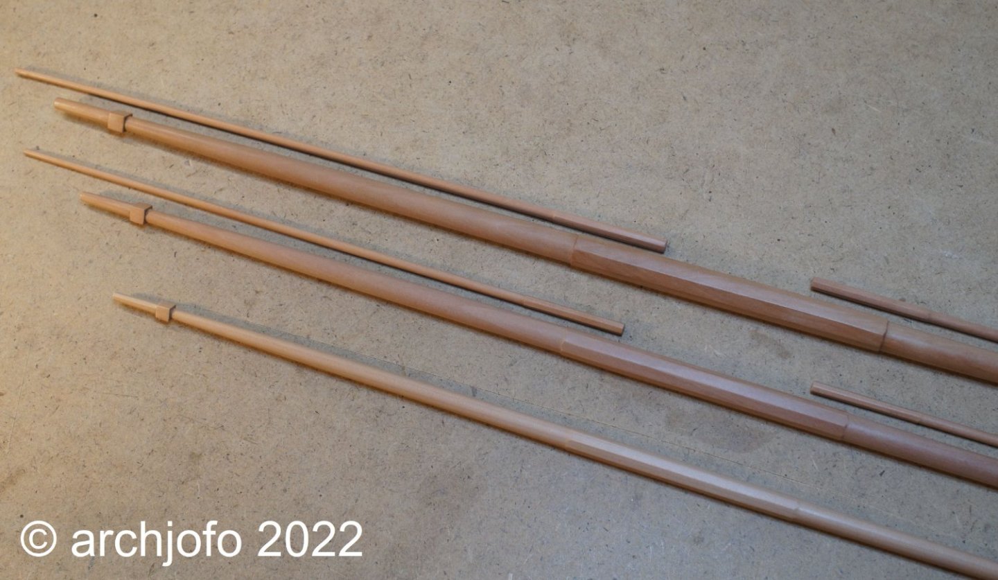
@Gahm @matiz @FriedClams @Vladimir_Wairoa @dvm27 Hello, I am very grateful for your interest and the nice comments, as well as for the many LIKES. That motivates immensely. Continuation: Production of the yards - Vergues We continued with the production of the yards. With the help of G. Delacroix I was able to clarify a few questions about the dimensions of the yards. Accordingly, I used the following table for the dimensions of the masts, yards and spars of the "La Blonde", which is identical in construction to the "La Créole". Source: Monograph on La Créole by J. Boudriot, page 56 There, among other things, the diameters are given in addition to the lengths. As a rule, the small diameter of a yard is 2/5 of the large diameter, as I could learn from G. Delacroix. As you can see on the following pictures, the lower yards with the studding sail booms have been made so far in the meantime. Various details on the yard arms, such as for the installation of sheaves for the sheets still require final clarification. Also with the studding sail booms there are still questions about details, as shown in the following example of the model of the "Le Cotre 1830". I would be very grateful for any suggestions and hints. Source: Modèles Historiques au Musée de la Marine - Volume 2 - Jean Boudriot To be continued ...


-
It's hard to believe that this is 1:350 scale. To produce these tiny details so cleanly and accurately is worthy of special recognition. A very nice modelship, congratulations.
-
Hello , very nice work, and good research.
-
Hello Nils, again really a beautiful model become, with all the many beautiful details. Also the presentation will be fitting.
-
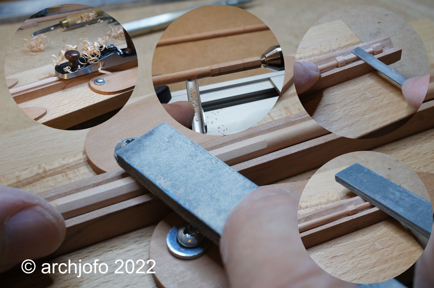
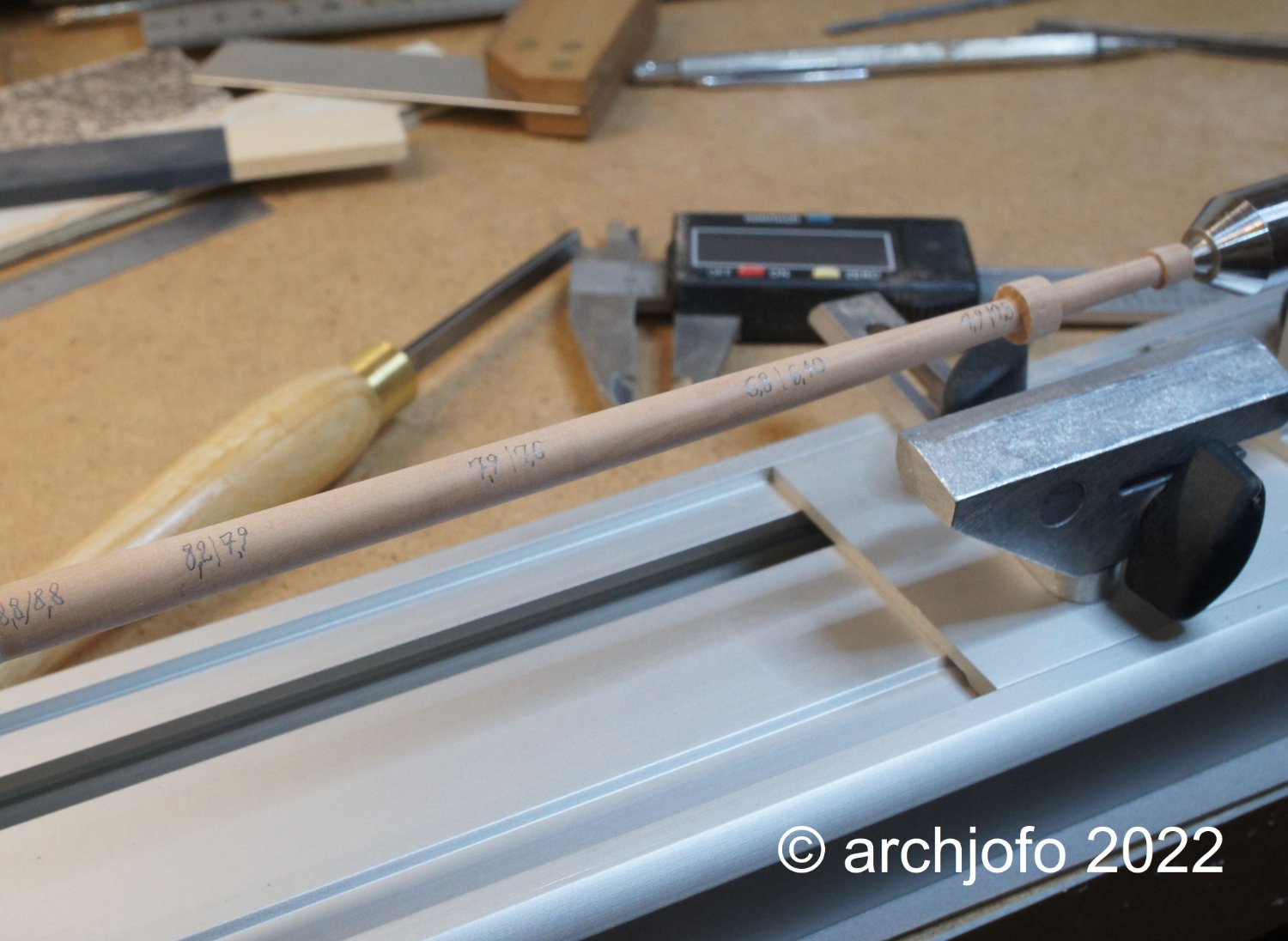
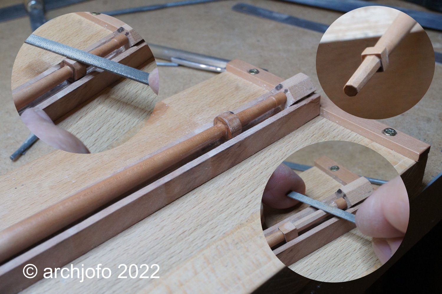
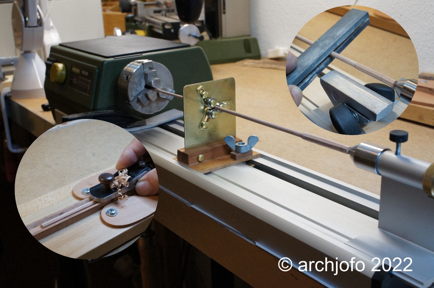
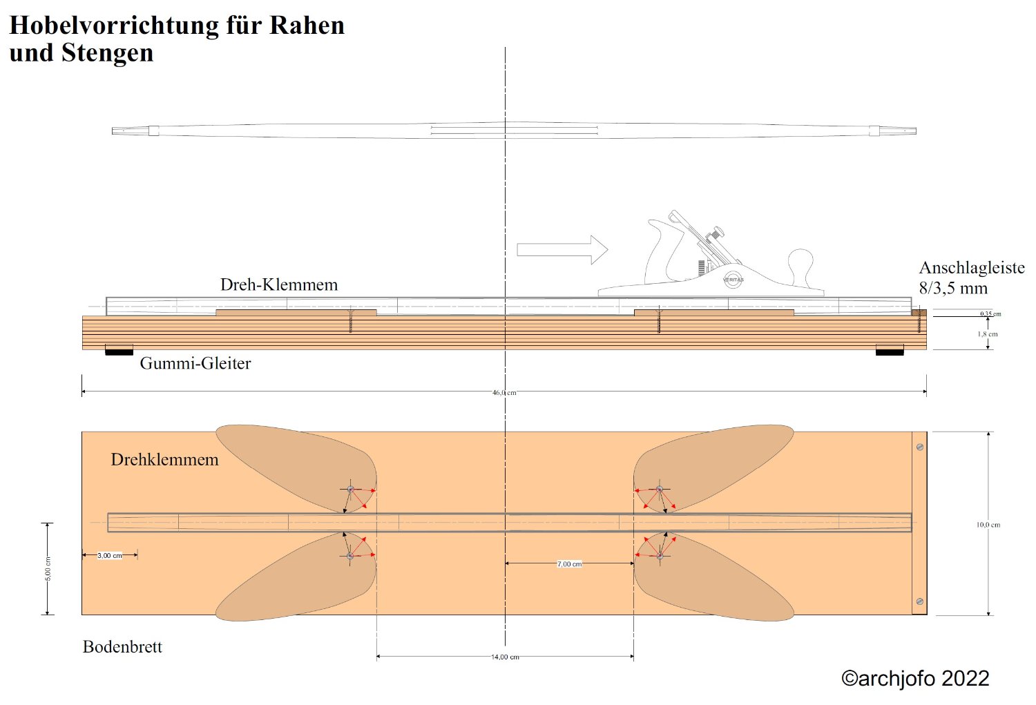
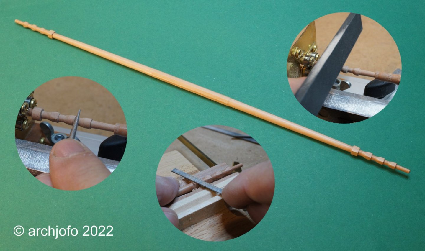
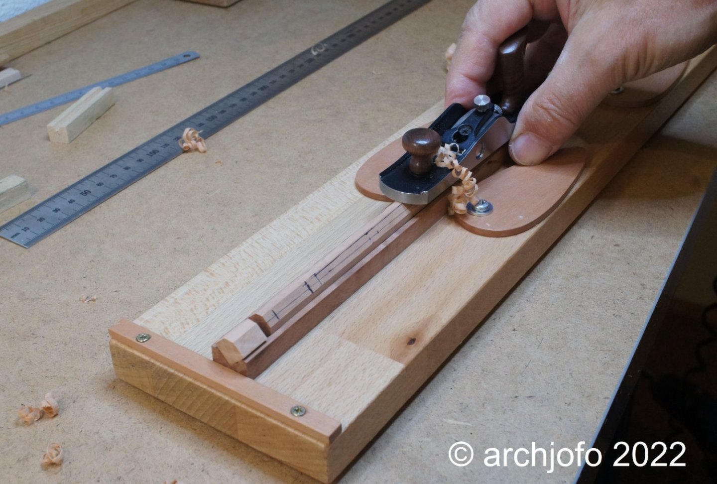
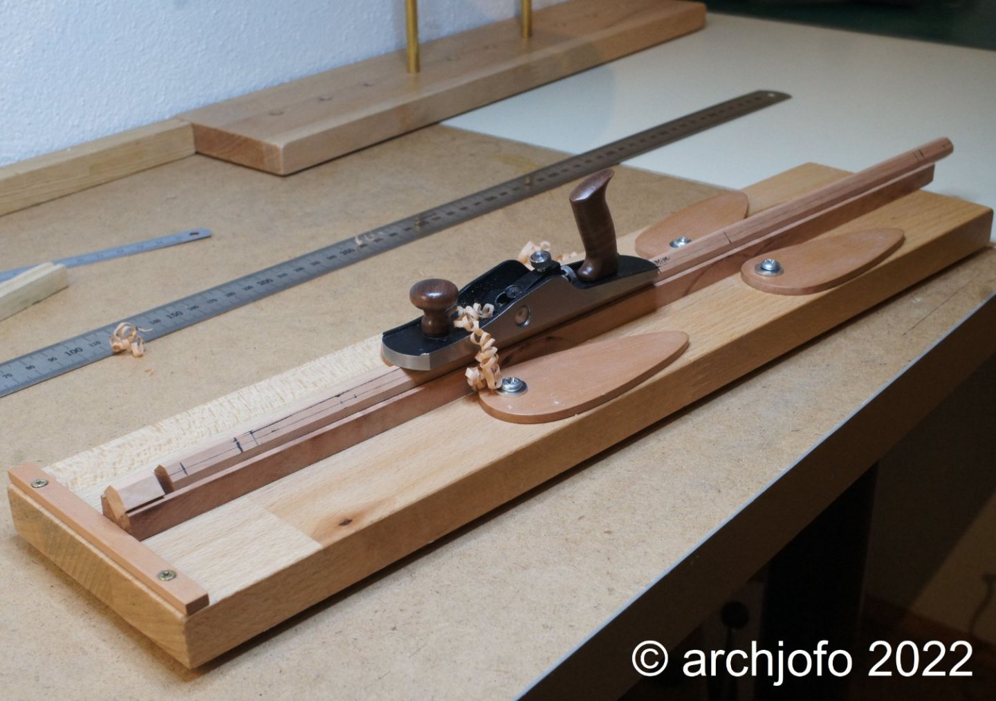
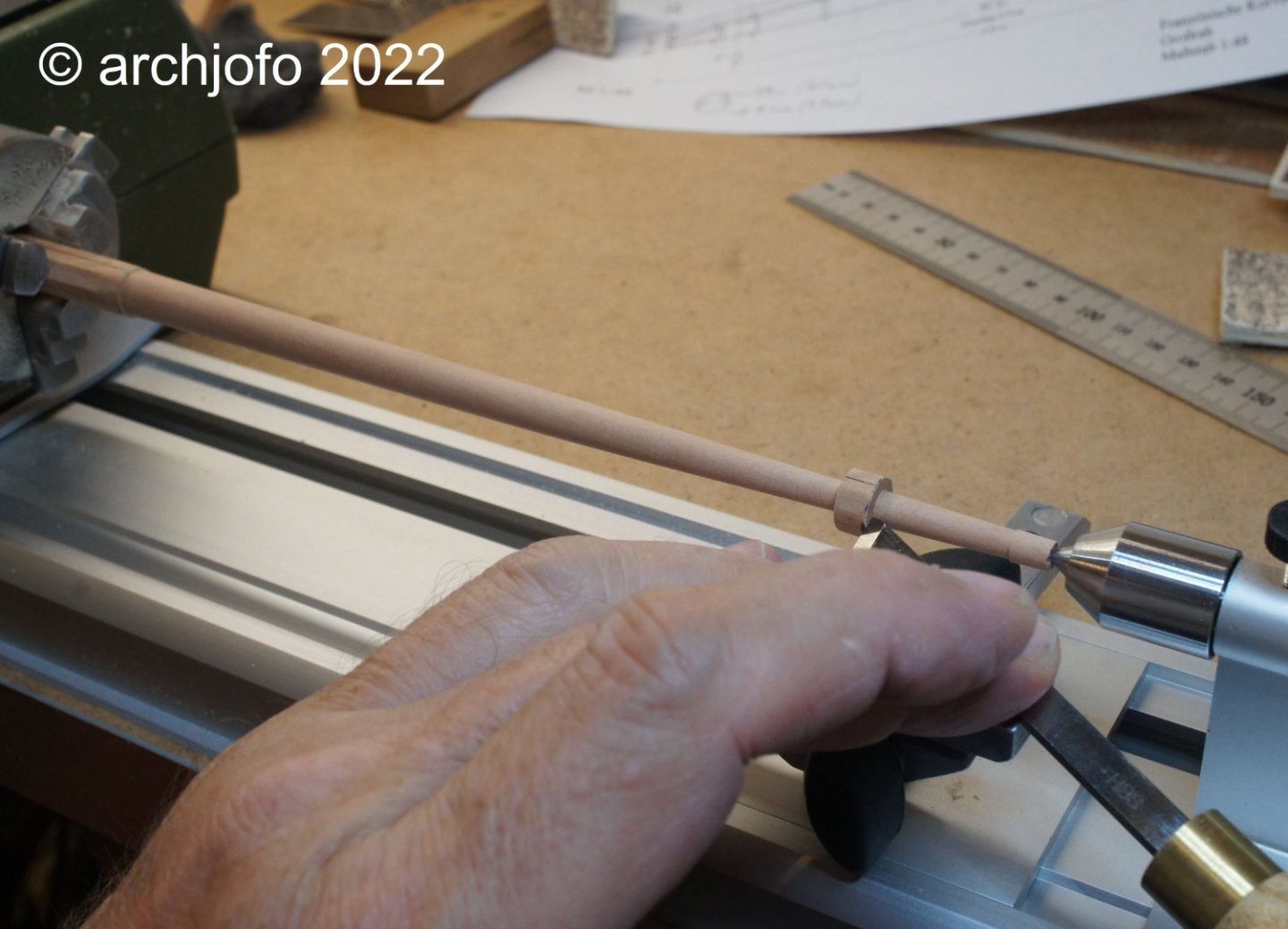
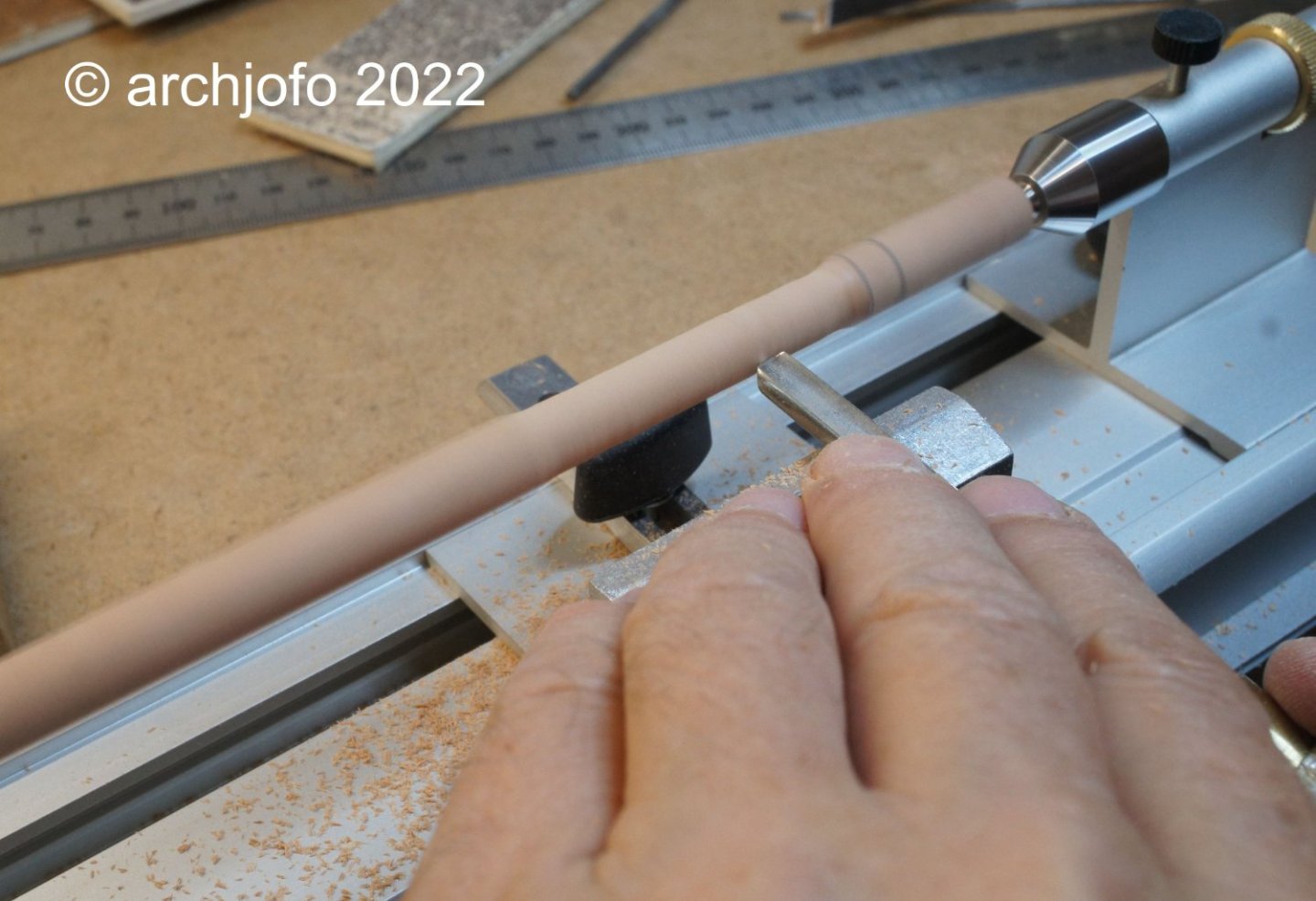
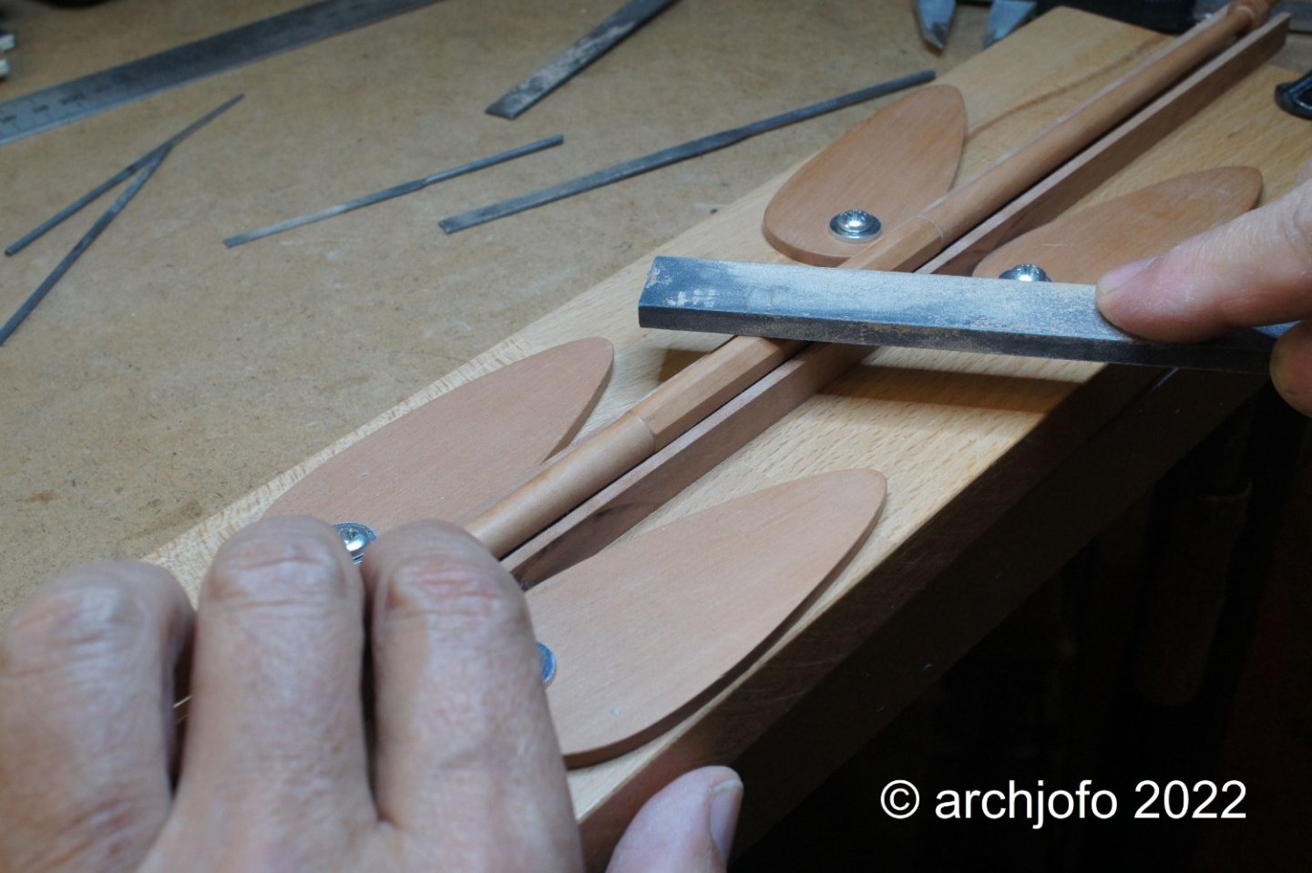
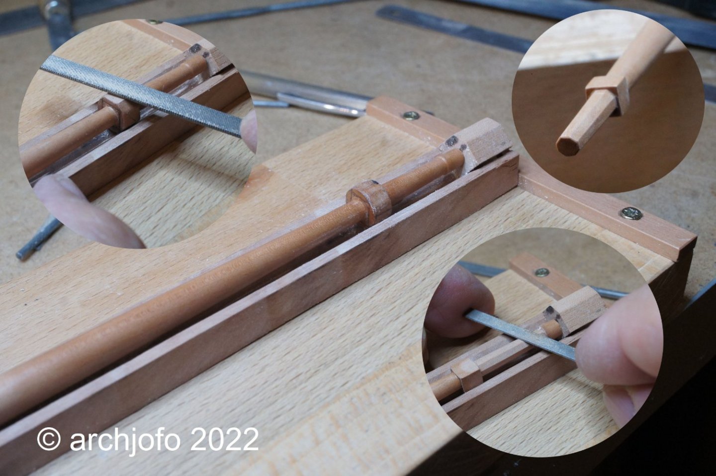
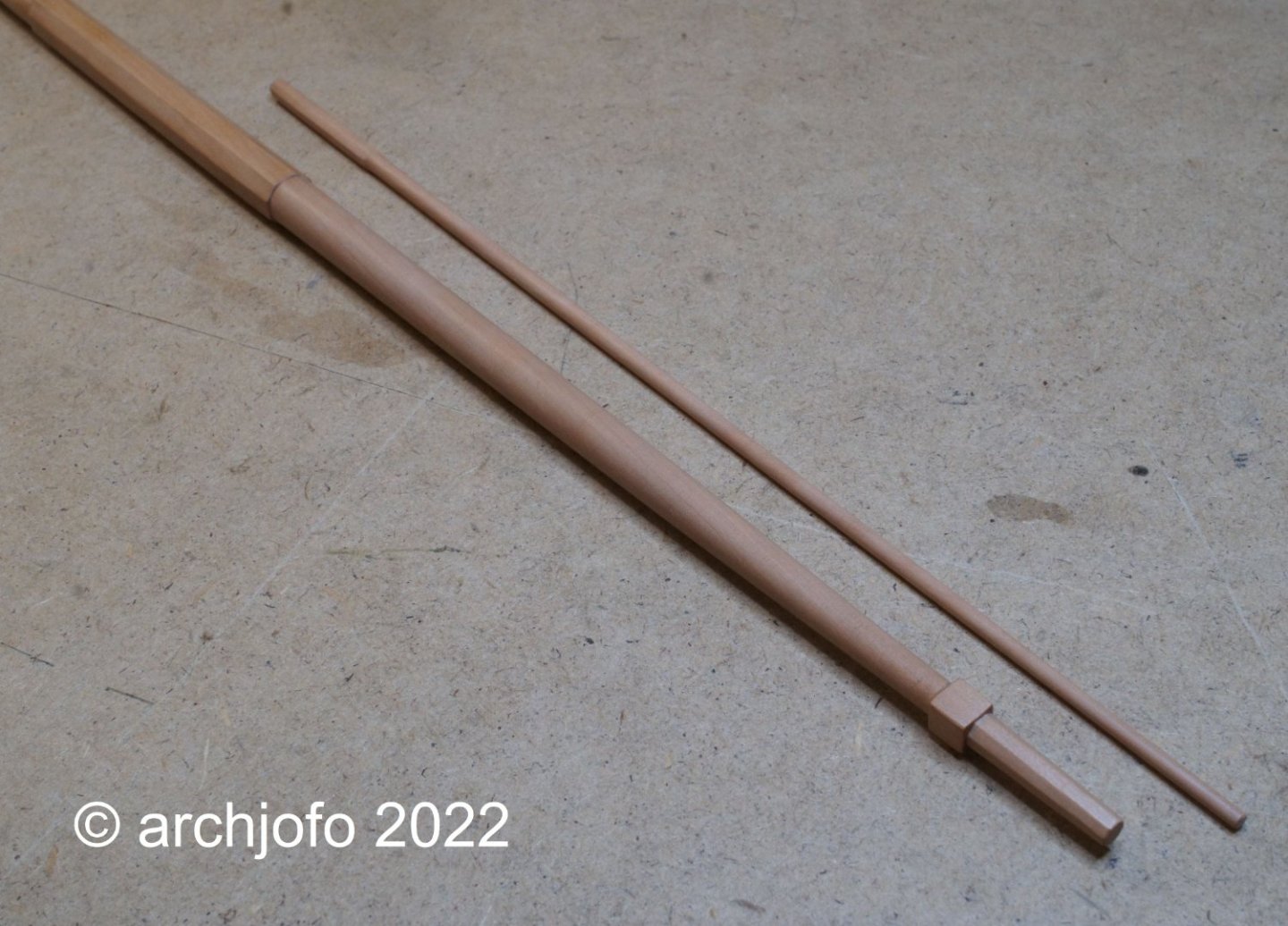
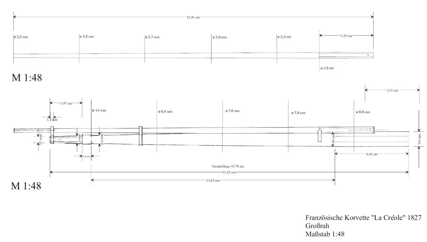
Making the yards - Main yard - Grande vergue Before starting to make the yards, I made myself a planing jig in advance, inspired by Ed Tosti's build report for the clipper "Young America" in the MSW, as shown in the drawing below. Rotating and locking clamps allow lumber of various widths and lengths to be fixed in place for machining, especially with a wood planer. To make the main yard, I prepared a drawing with dimensions based on the plan by J. Boudriot. The next two pictures show how the holding device mentioned at the beginning of the report can be used in practice. It performs valuable services in the manufacture of yards. For example, a wooden strip with a V-shaped groove was clamped in place. A square timber inserted in this way can easily be planed into an octagonal timber. In this case for the main yard and later for the leeward spars. These timber blanks are then much easier to machine on the lathe. In addition, they are used to roughly preform the octagonal areas of the yards or studding sail booms. With the following pictures I illustrate the further processing steps in the yard production. In contrast to the main yard, the studding sail booms are much more delicate logs with diameters of 3.7 to 2.2 mm, which had to be machined. So that this succeeds also without breakage, I built for this with simple means a small steady rest. With this I can bring small ball bearings for round timber with diameters of 1 - 10 mm into position for support. In the meantime, the small tool has already proven itself very well. On the last picture you can see the first results. To be continued ...


-
This is the finest woodwork. It is always a pleasure to be able to share in the progress.
-
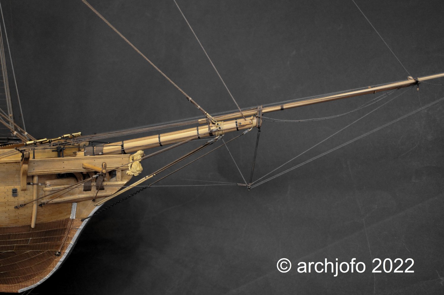
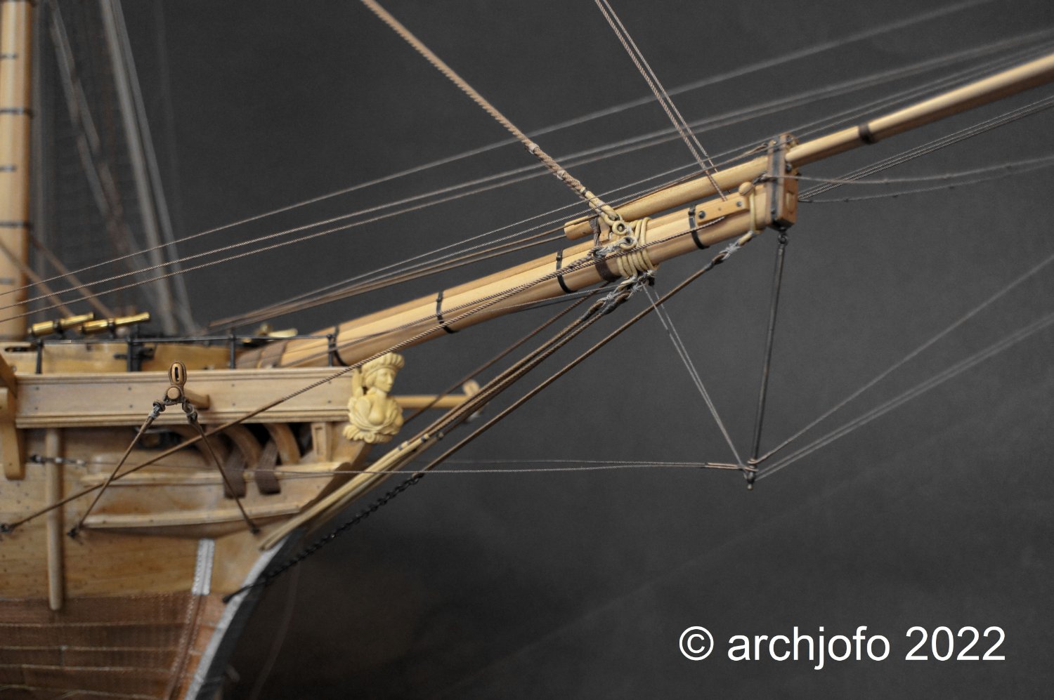
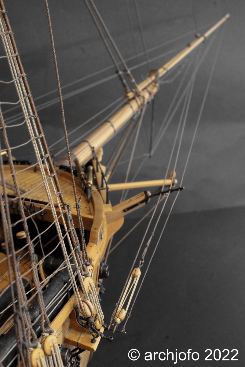
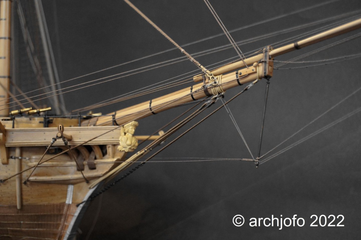
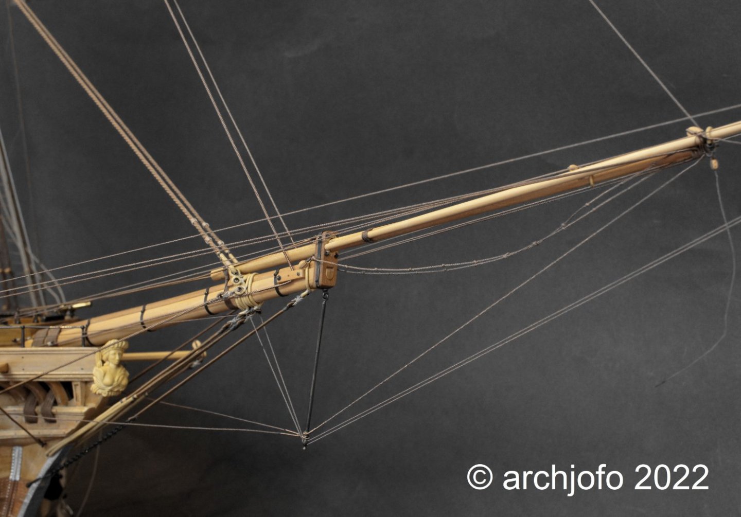
Hello colleagues, I am very pleased that despite a long break there is still interest in the progress of my model. A hearty thank you for it. Completion: Standing rigging for jib and outer jib boom - Bâton de foc et bâton de clinfoc After the final work on the standing rigging for the jib boom and the outer jib boom, I can also finish this chapter. So the standing rigging for the French corvette is finished except for a few minor details. Accordingly, here are a few pictures that give an overview of the bowsprit rigging. Soon I will dedicate myself to the production of the yards. So I am looking forward to work more intensively with wood again. To be continued ...


-
Hi Giampiero, fantastic work !
-
@Dziadeczek Hello, you are right, but in this drawing I was only concerned with the connection of the guys by means of thimble. I based the tackle on the model of the L'Inflexible.
-
Hello Brian, almost finished ! This has become a wonderful model. A lot of beautiful detail finishes. Maybe you'll make it to the 160th anniversary after all. Good luck.
-
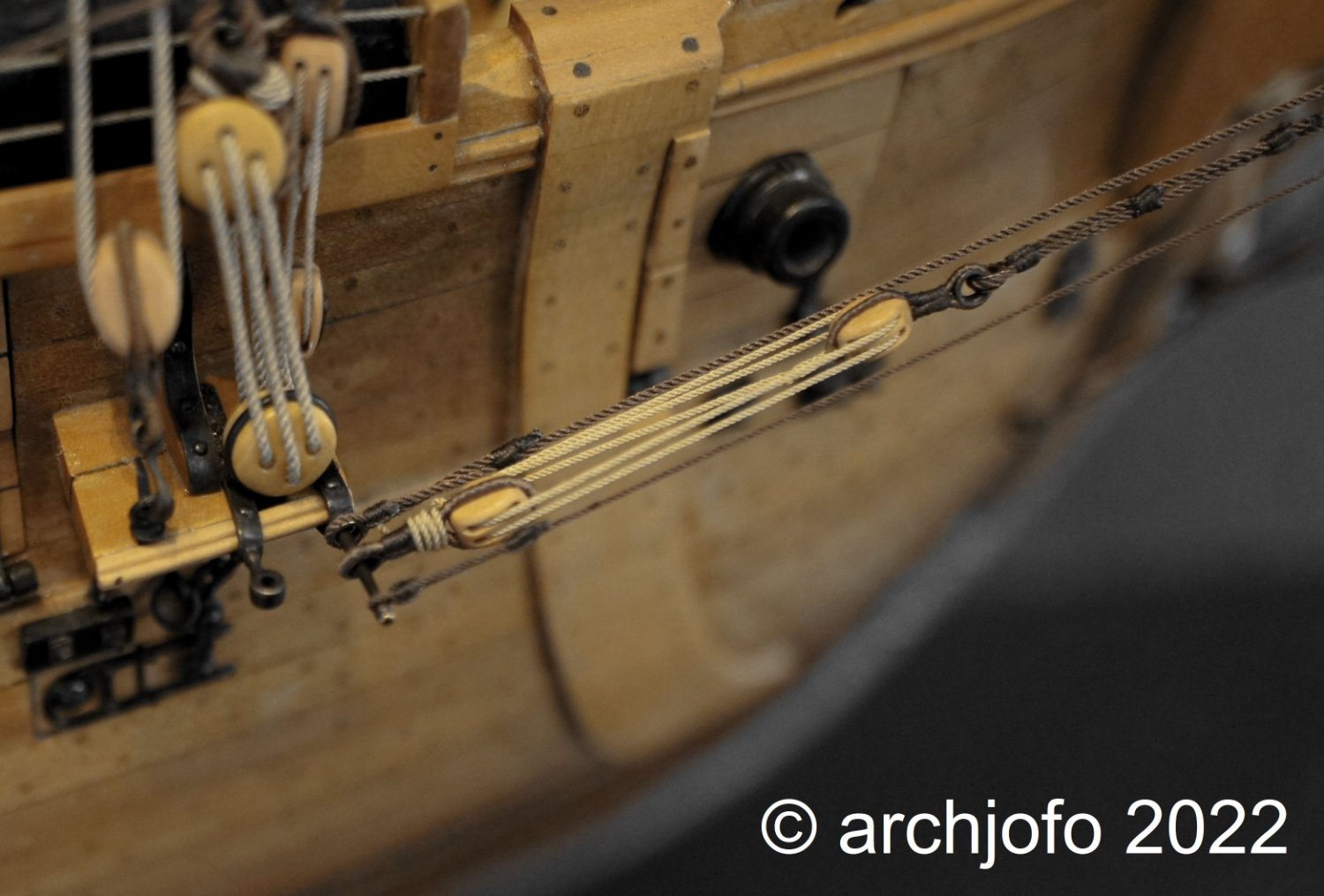
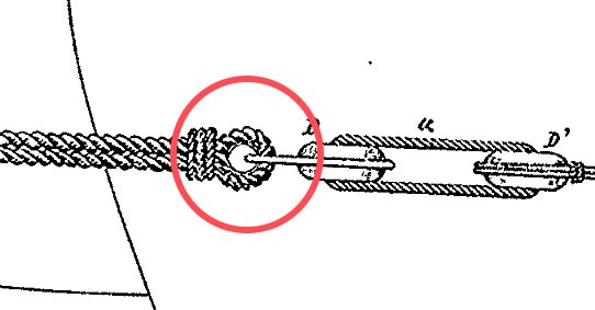
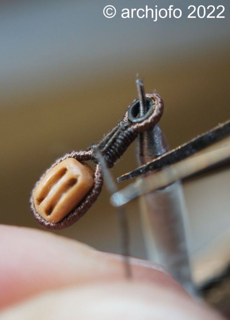
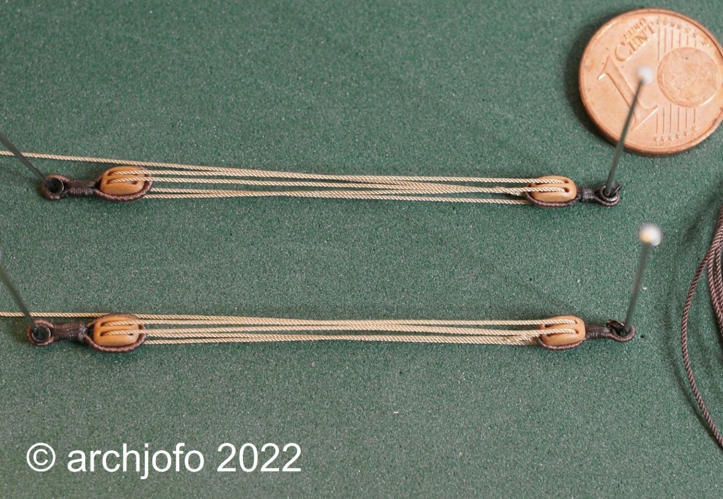
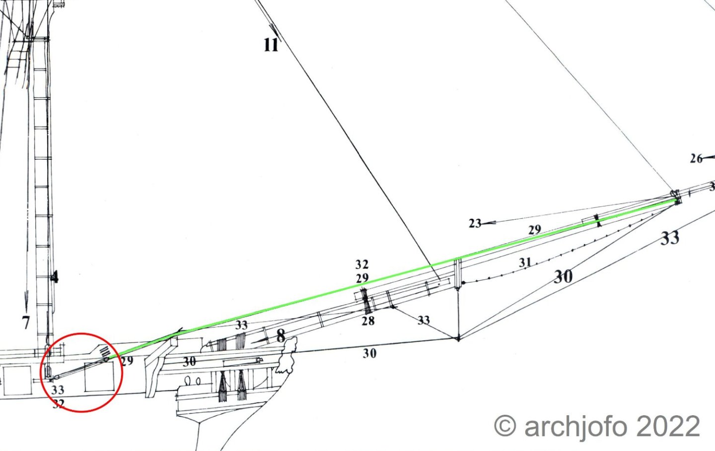
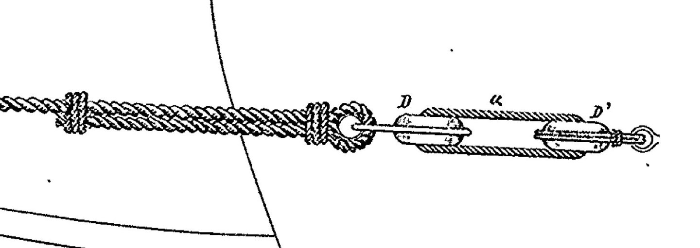
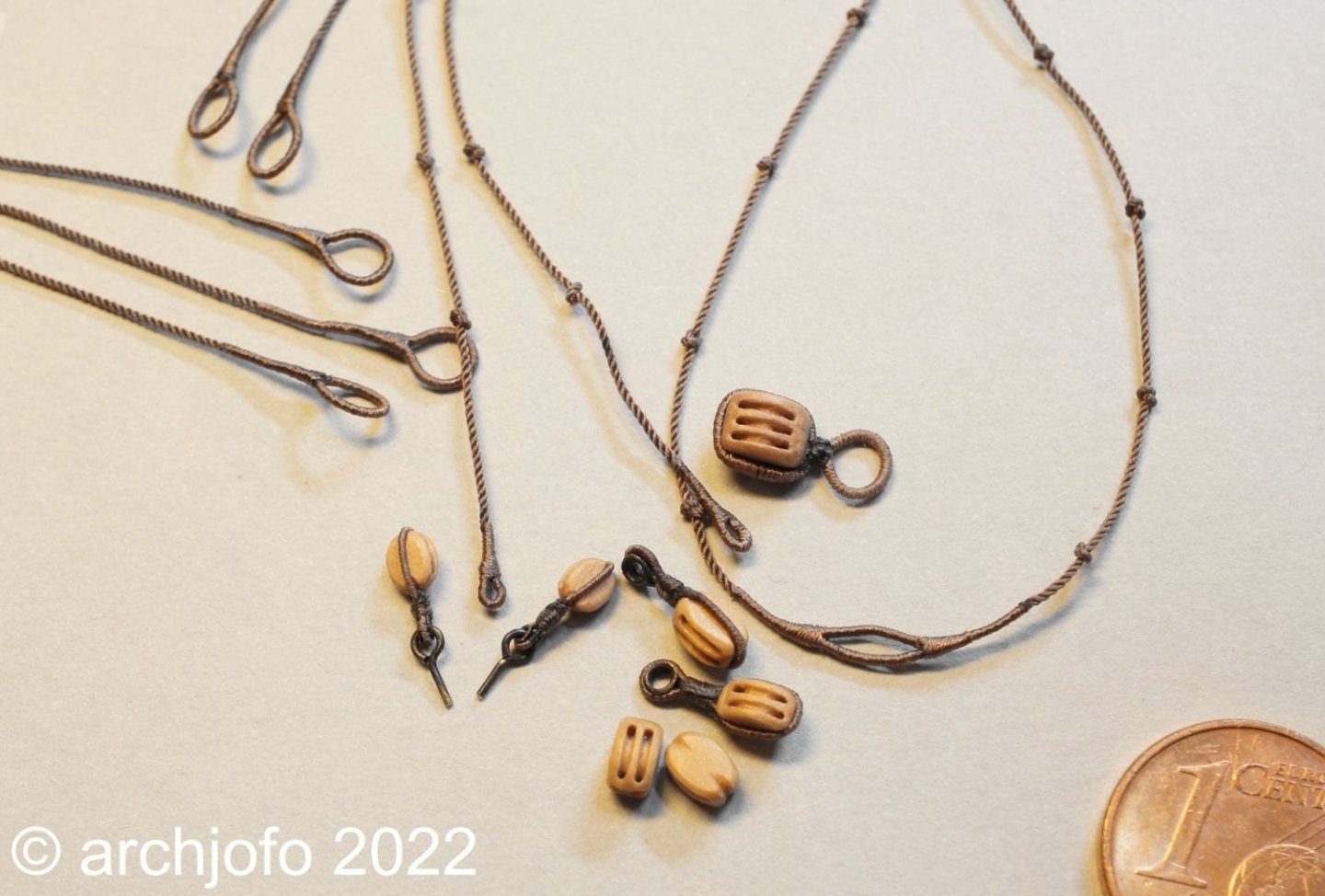
@Wishmaster Thank you vor the kind words. And to all the others, thanks for the LIKES, The days are getting shorter again, so the times spent in the basement shipyard are getting a bit longer again ... 😁 Continuation: Standing rigging for jib and outer jib boom - Bâton de foc et bâton de clinfoc This is a continuation of my last construction report. To finish the rigging work for the standing rigging of the bowsprit with the jib boom and outer jib boom, the jib boom and flying jib boom stays still had to be fastened. The jib boom was stabilized laterally with two jib guys on each side, one of which was fixed by means of a tackle. Source: Monograph La Creole by J. Boudriot p. 129 For the detail of the tackle I followed the model of L'Inflexible and the Atlas du Génie maritime. Source: Extract from Atlas du Génie maritime, annexe No. 1, Pl. 10 Attached are two pictures of the implementation and the completed tackles, consisting of double blocks. The ends of the jib guys are then fastened by means of thimbles and seizings. See you soon ...
-
Hi Thomas, this will be a particularly beautiful model. The last pictures of it is admirably beautiful.
-
Hello Greg, the belaying pins look very realistic. A very fine shape. In addition, the Speedwell will be a fantastically beautiful model. The beautiful woodwork is admirable. The standing rigging of the lower masts also looks really great. I look forward to the progress of the work.
-
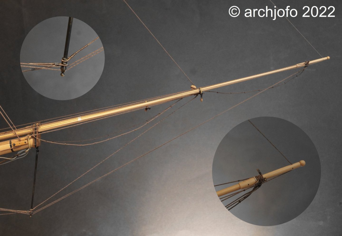
@Dziadeczek @Nunnehi (Don) @albert @AJohnson @Pirate adam First of all, I would like to thank you very much for the interest in my work and the nice comments. Also I would like to thank you for the many LIKES. Continuation: Standing rigging for jib boom and flying jib boom - Bâton de foc et bâton de clinfoc On a grommet strop (ring rope) as a base, the standing rigging for the jib boom was laid on top. Building on this, first come the footropes, which are slipped over the boom with a served cut splice. At both ends the footropes had a served eye for tying to the top of the bowsprit at the back eyebolts, to which the single blocks for the bowlines of the fore top sails were also attached. In order to guarantee the sailors a secure hold during their work, knots were worked into the 22 mm (ø 0.46 mm in model scale) thick rope of the footropes at intervals of two feet, e.g. as Turkish head knots. In 1:48 scale, I think it seems quite sufficient in this case to make overhand knots. After the abolition of spritsail yards in the 19th century, the jib boom guy and flying jib boom guy were often spread to the cathead by means of iron outriggers, thus giving the jib boom and flying jibboom greater strength laterally. Accordingly, this was also the case with the La Créole. The rigging was mounted on iron spike-like outriggers on the fore channels. In principle, the jib boom guys perform the same function as the shrouds, hence their designation by the French, such as Haubans bout-dehors beaupré, which corresponds to the jib boom guy. The jib boom of this corvette had two 22 mm dia. ropes on each side, one of which was stiffened with tackles and double blocks. The jib boom guys were attached individually with served eyes to the top after the footropes, and as already described, led through the outriggers to the cathead to the fore channels for mooring. The area of the lead through the booms was served against rubbing. Next came the jib boom stay, also a 22 mm dia. rope. This was slipped over the top with a served eye and attached to the iron martingale in a groove provided for it. Underneath, the two jib boom stays were slipped over as counterparts, which were then attached to eyebolts on the port and starboard sides of the bow. With the already shown triple block for the bowlines and the fore topgallant stay, the rigging of the jib boom came to an end. The following picture shows the rigging elements that were partially mentioned before. The second picture shows the finished jib boom top. After all, six ropes have been laid there, as well as the grommet and the triple block strop. And in the last step, the flying jib boom was rigged, as can be seen in the last picture. Building on the grommet, the following ropes were stripped over the flying jib boom top: - footrope ø 19 mm (ø 0.40 mm in model scale) - flying jib boom guys ø 22 mm (ø 0.40 mm in model scale) - pair of flying jib boom guys ø 19 mm - strop with 2 thimbles for the bowlines Finally, the fore topgallant stay ø 15 mm (ø 0.35 mm in model scale) could be passed through a disc in the flying jib boom top and fitted in the forecastle. See you soon ...

-
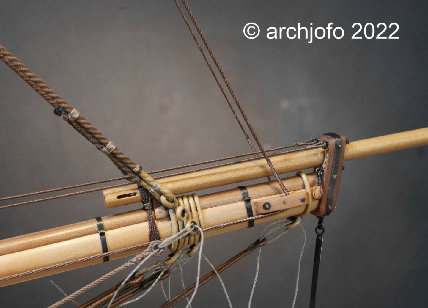
@French Mr Bean @Gahm @jdbondy @dvm27 Hello, Thank you in advance for your nice comments and the many "likes". I am always happy and motivated by positive feedback. Constructive criticism and suggestions are still very welcome. Greg, I'm also very glad that my rigging inspires you. Continuation: Standing rigging for jib and outer jib boom - Bâton de foc et bâton de clinfoc First I had to attach the jib boom. I lined the jib boom passage in the cap of the bowsprit with a specially split leather (d=0.2 mm). The jib boom was placed on the prepared wooden pad or spacer so that it runs parallel to the bowsprit. Then I lashed the jib boom to the bowsprit analogous to bowsprit gammoning. I added small details to the cap, as can be seen in the last picture. These are single blocks (l = 3.5 mm) on each side for the bowlines of the fore topsail. Next to the block you can also see the leather lining mentioned at the beginning. Sequel follows …

-
USF Essex by mtbediz - FINISHED - 1:50
archjofo replied to mtbediz's topic in - Build logs for subjects built 1801 - 1850
Wonderful model ship. Fantastic Work! -
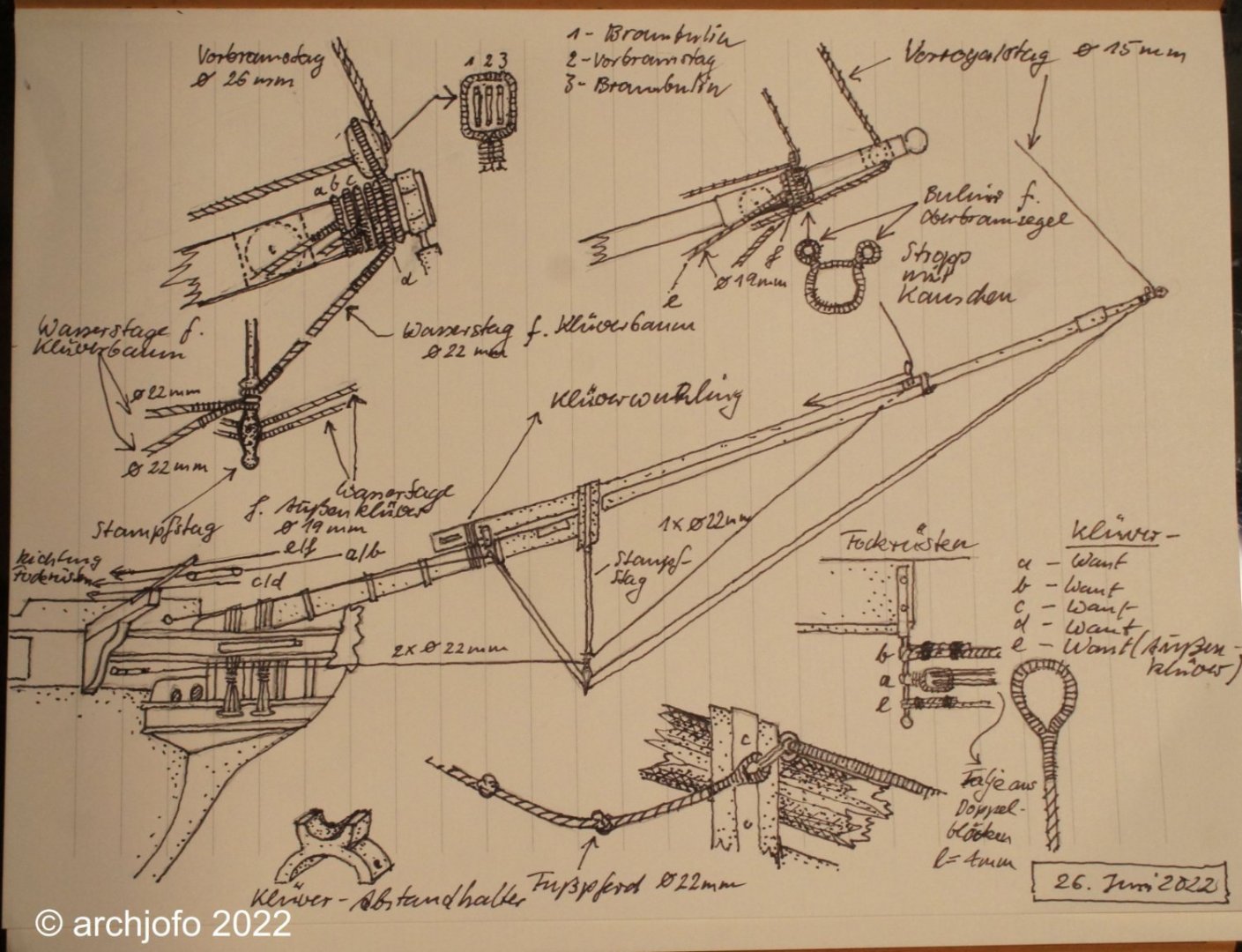
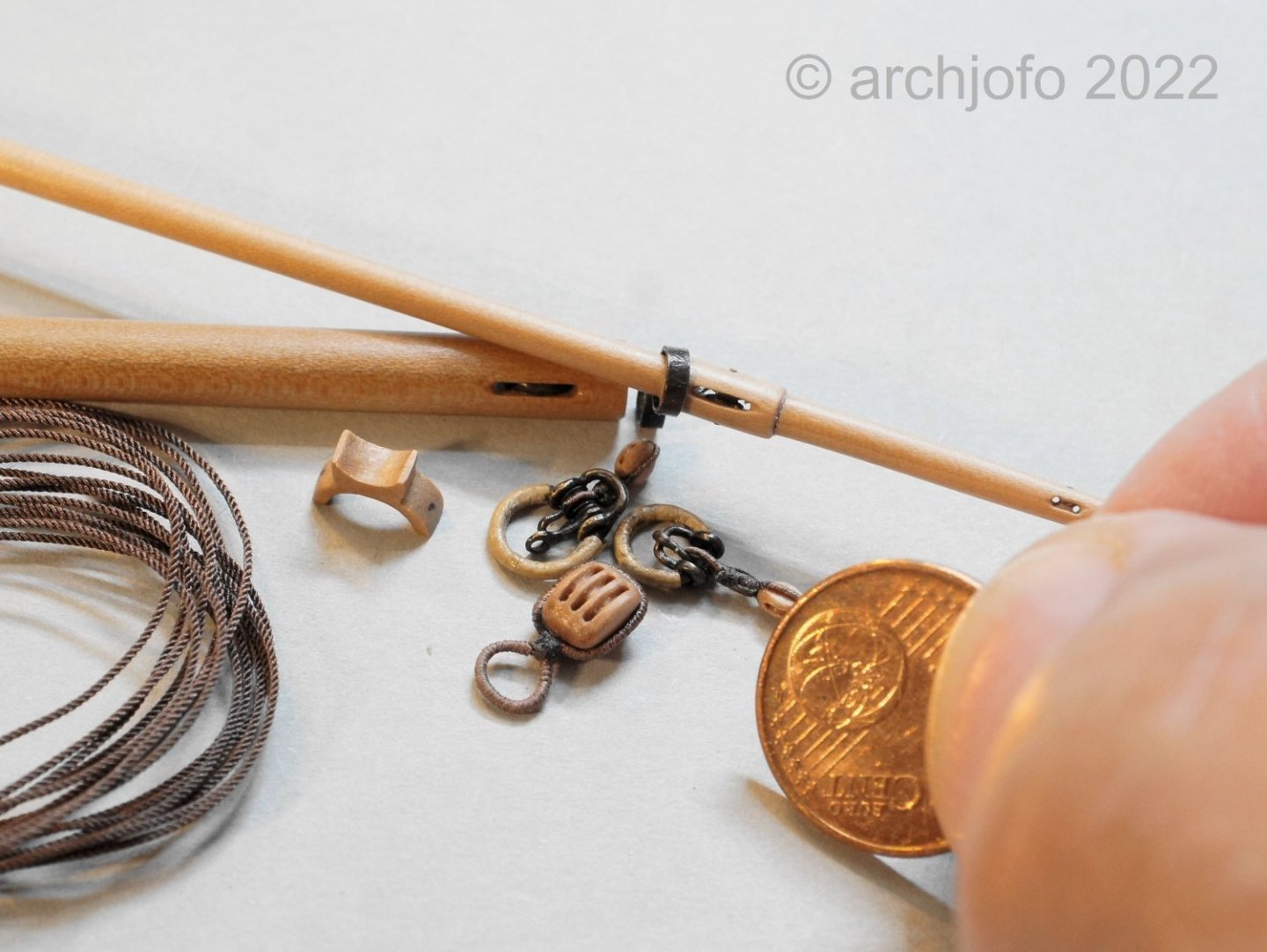
Standing rigging for jib and flying jib boom - Bâton de foc et bâton de clinfoc To complete the standing rigging (fore topmast stay and fore topgallant stay) for my French corvette, it finally became necessary to attach the jib and outer jib boom. Since these are very delicate and therefore very sensitive parts of the model, I delayed their assembly as long as possible. One or the other ship modeler might have already made the painful experience that a small carelessness leads to the breakage of these booms. Before the realization, extensive research was done on the required detail elements. The information in the monograph on La Créole by J. Boudriot is not sufficient for this. In addition, some points concerning the guidance of the rigging (mooring in the forecastle), the dolphin striker (angular position) and the flying jib boom (length and attachment) had to be clarified. I tried to record the compiled results in my new sketchbook (the old one is already full), as can be seen below: After more intensive occupation with this topic, I have only realized what a wealth of detail it contains. However, a few open questions still remain, such as whether foot ropes were also attached to the flying jib boom and whether they were single or double. On the next picture you can already see some rigging elements with jib and flying jib boom. Besides the spacer and the triple block, the travelers are also shown. The so-called jib inhaulers are later guided over the single blocks attached to them. It should be mentioned that these are the smallest blocks of the model I have made so far, with a length of 2.8 mm. After making the necessary ropes, I will soon be able to start rigging the jib boom step by step, but more about that soon. To be continued ...
-
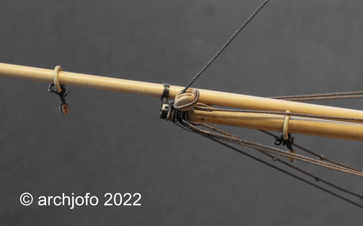
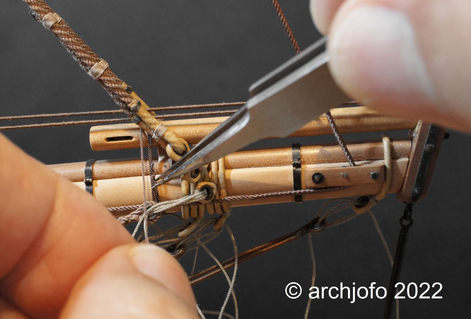
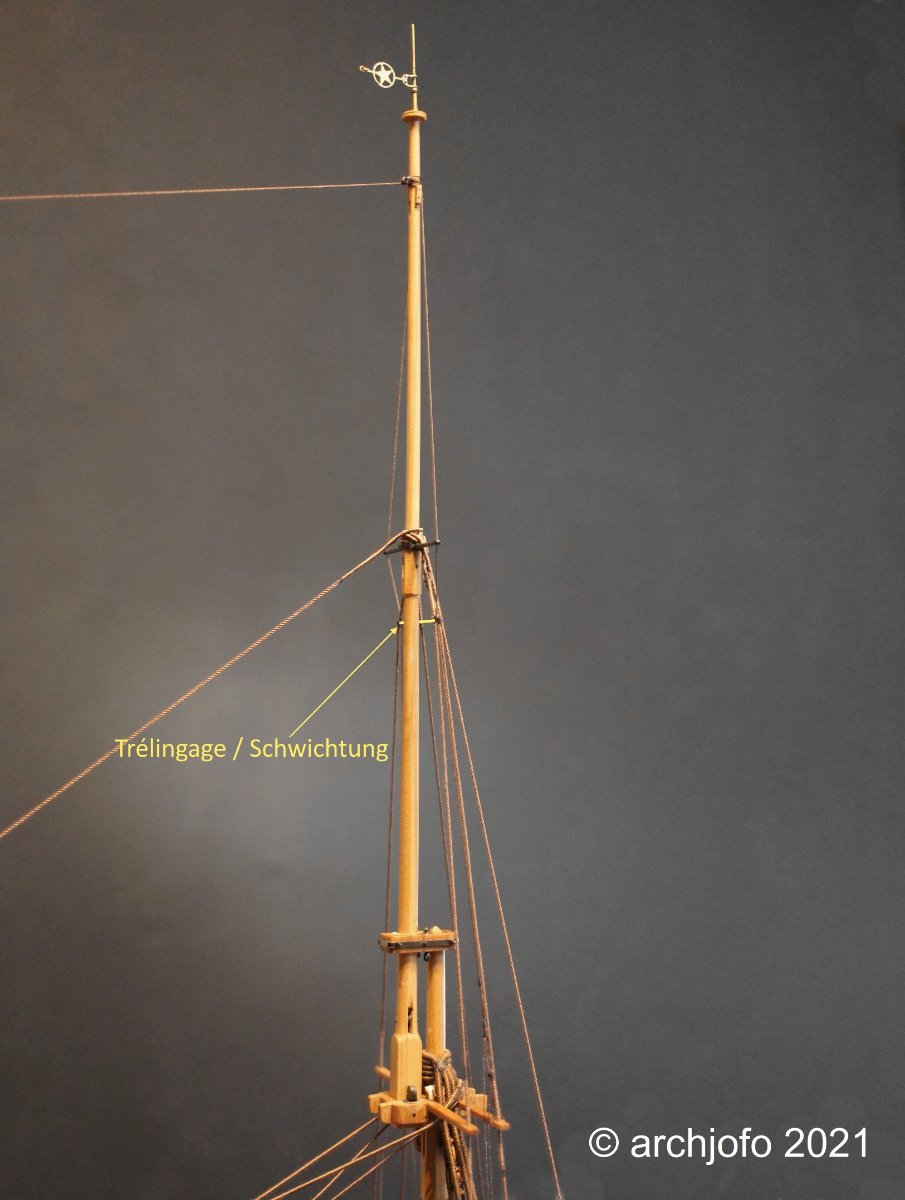
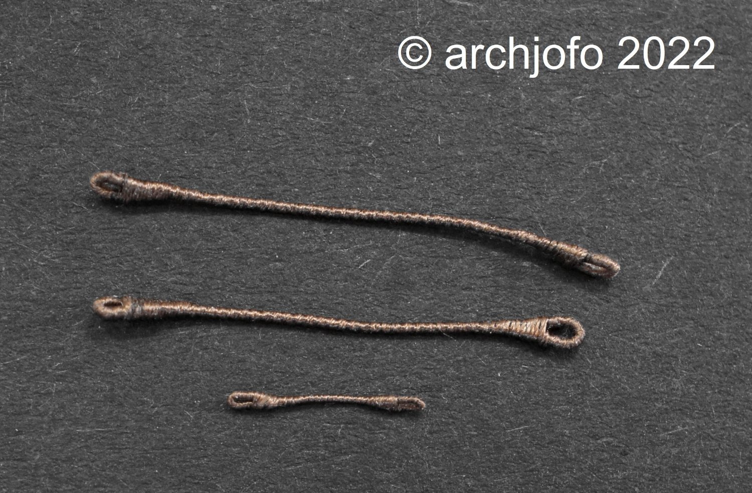
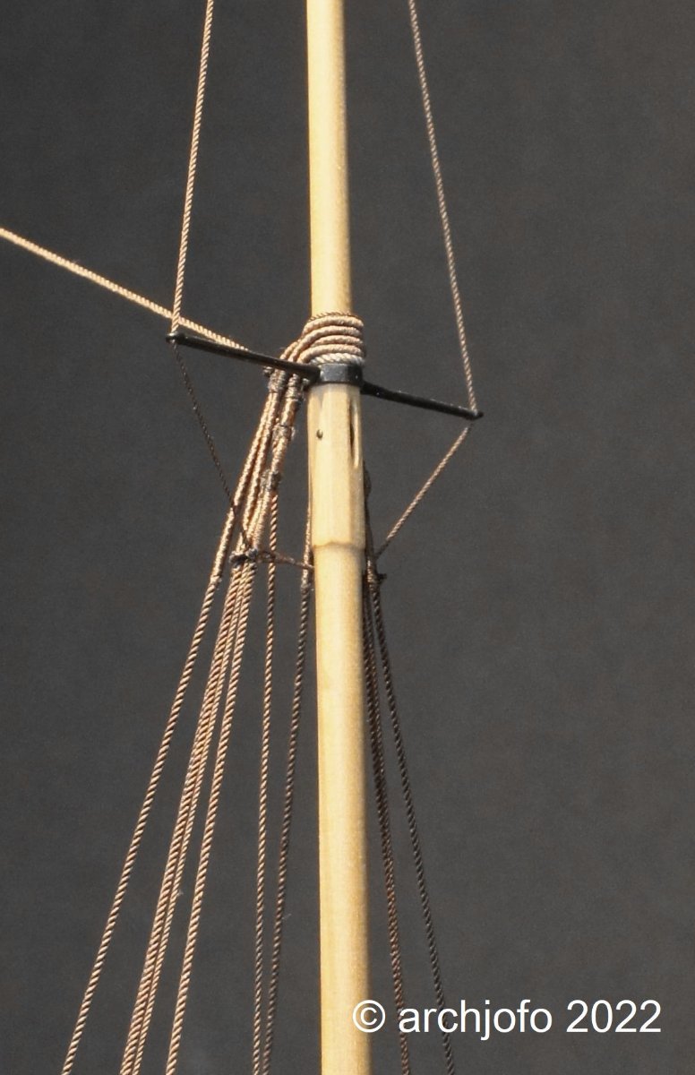
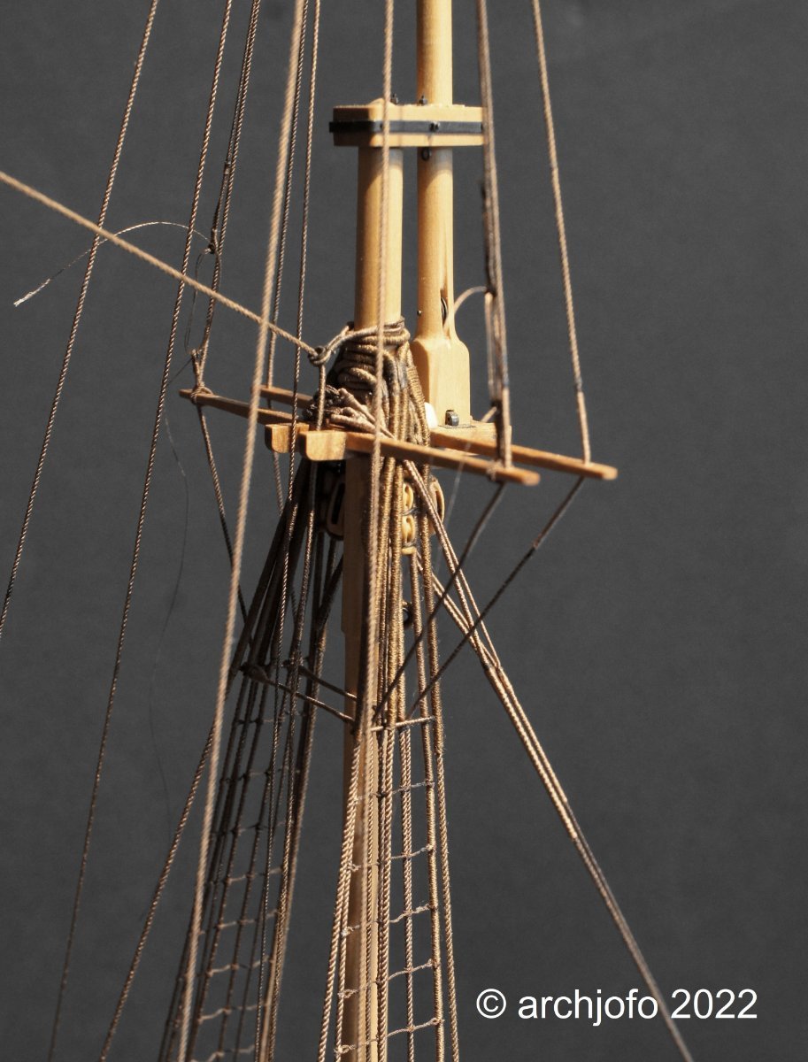
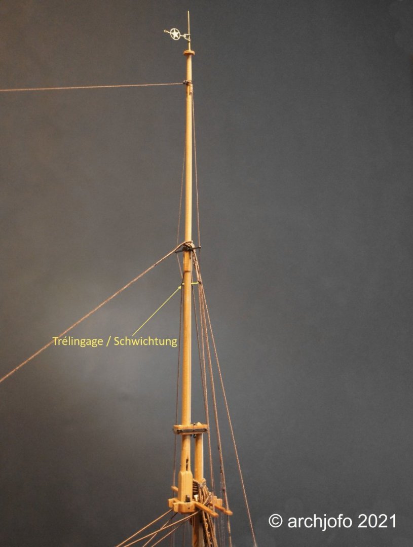
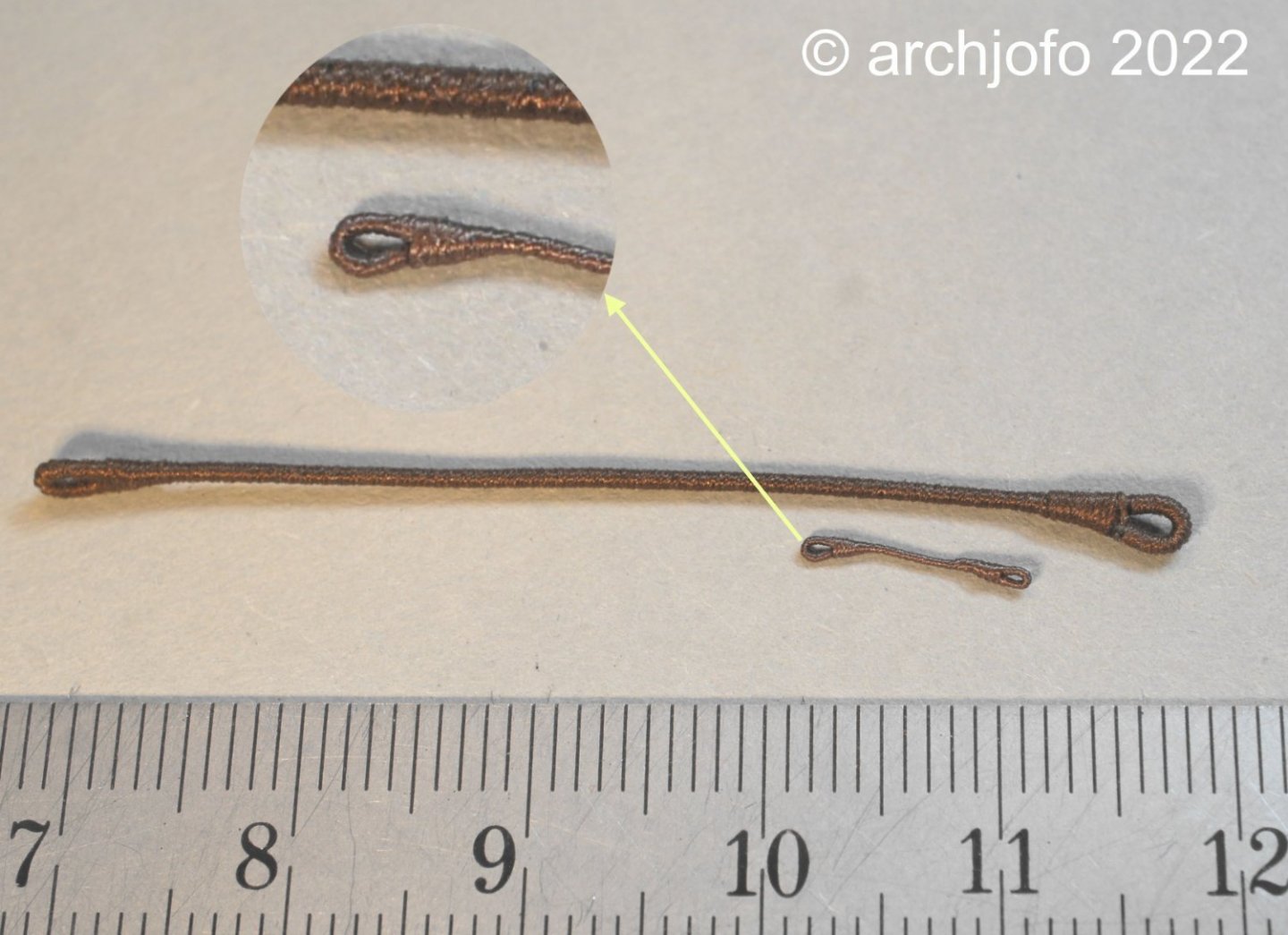
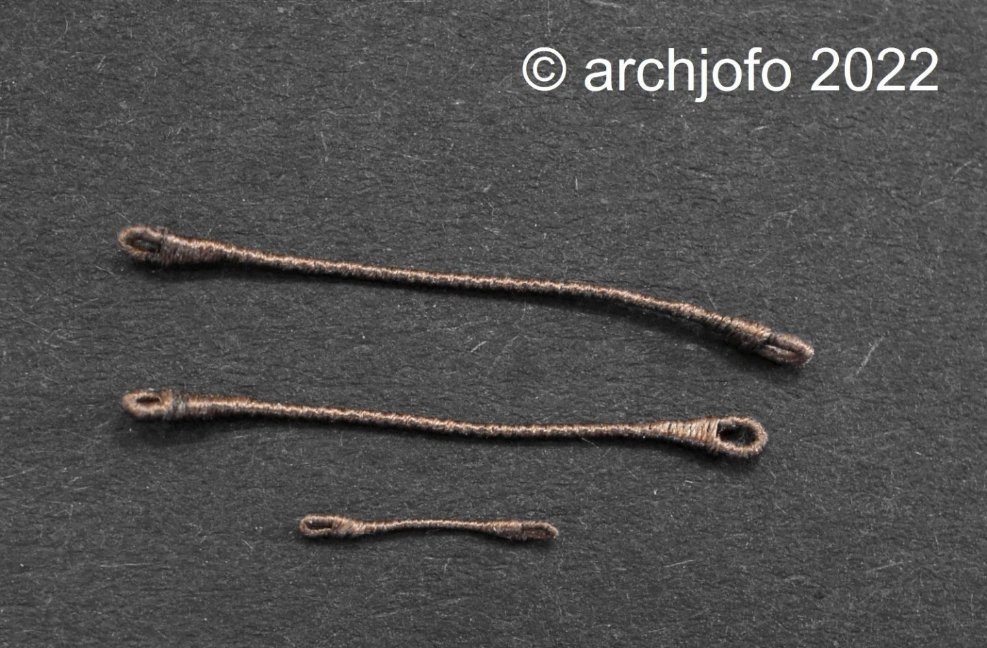
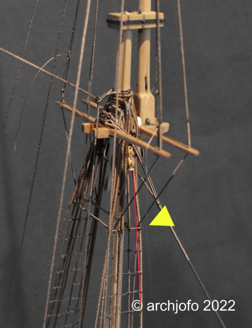
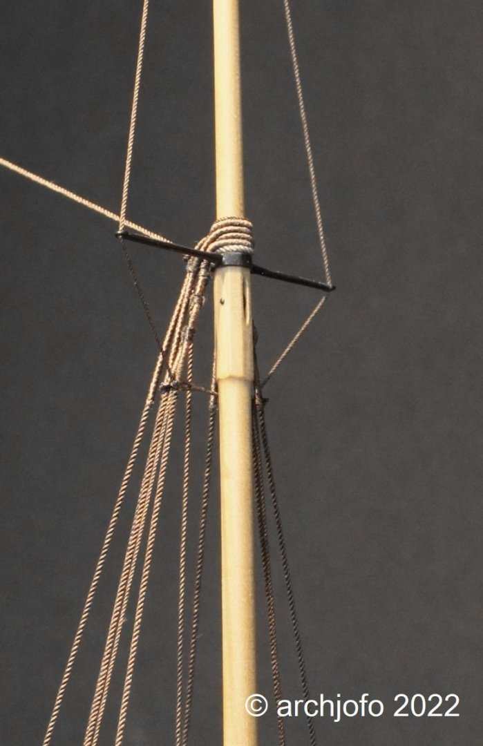
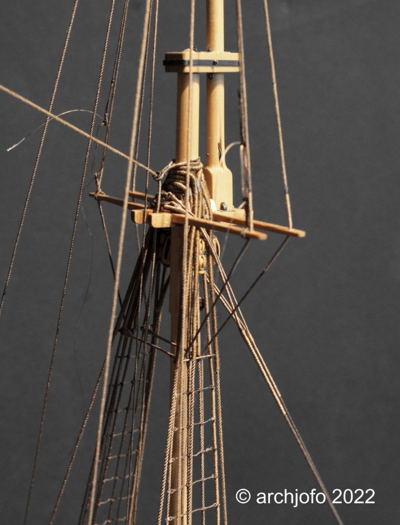
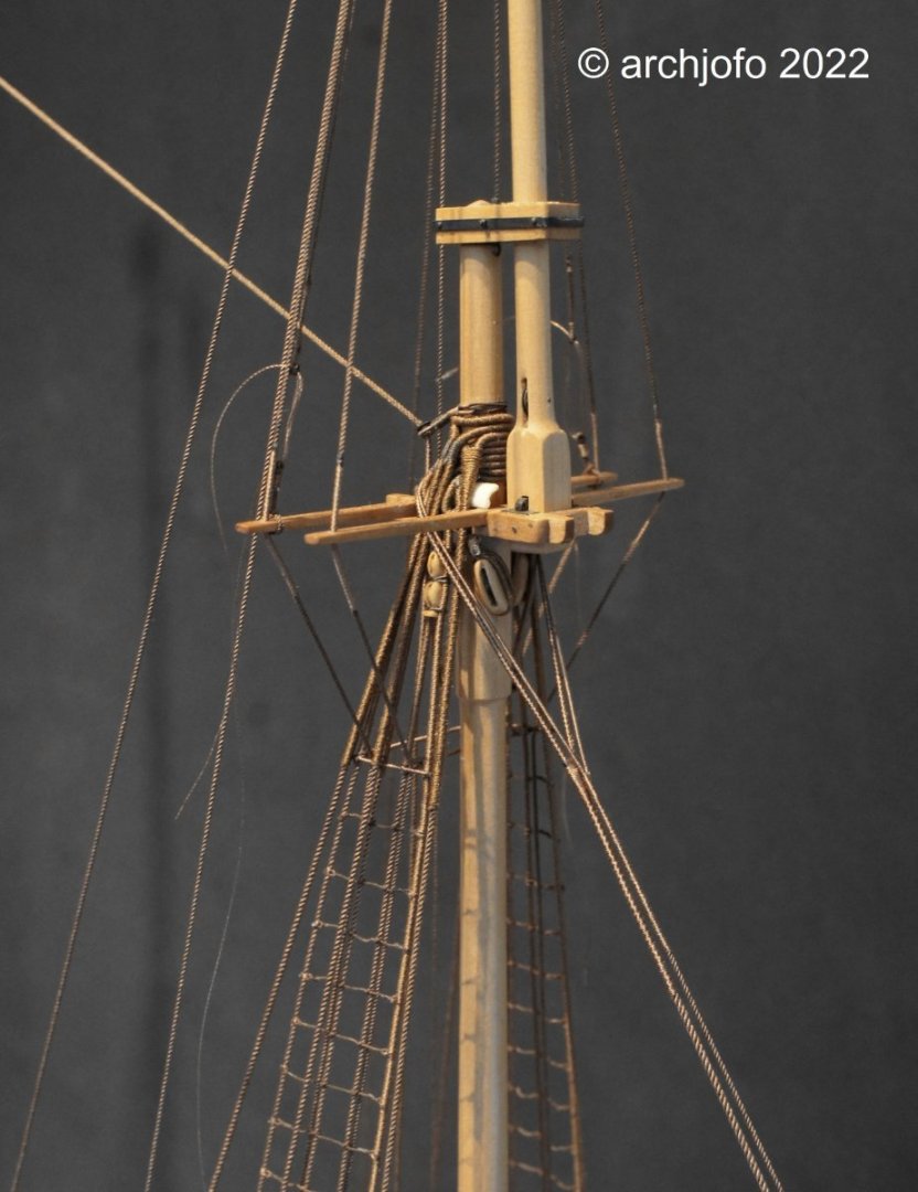
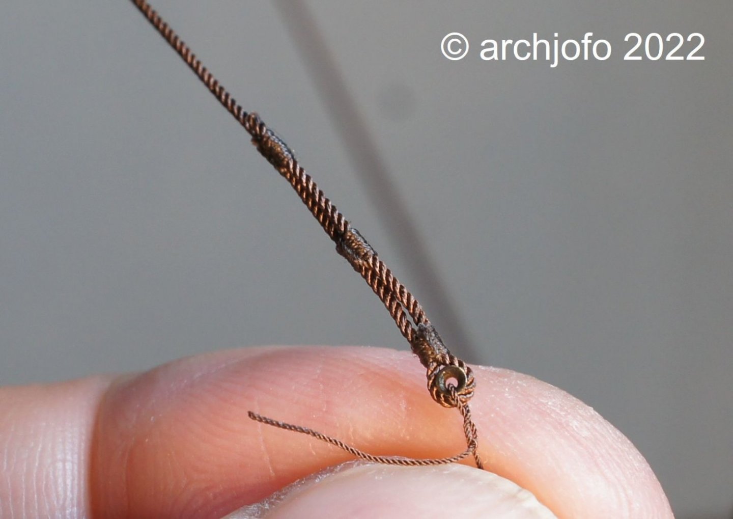
@jdbondy @Gahm Thank you for the interest and the nice comments. Also thanks to all for the many LIKES. Continuation: Catharpins - Trélingage As already explained some time ago in my construction report LINK, the shrouds of the topmasts and topgallant masts of the La Créole were also equipped with catharpins. The following picture shows that the catharpin for the topallant shrouds is much smaller compared to the catharpin of the lower shrouds of the mainmast. The next picture compares catharpin for the lower shrouds, the topmast shrouds and topgallant shrouds. With a length of about 10 mm from a 0.25 mm served rope, the catharpin of the fore topgallant shrouds was then lashed in place. The last pictures show the already lashed catharpins (0.35 mm served ropes) of the topmast shrouds. The comparison shows what happens if the length of the catharpins is not made accurately. When the shrouds are tightened, they give way and move outward. Therefore new catharpins had to be made again. To be continued ...
-
Continuation: Fixing the topgallant shrouds In the meantime, all topgallant shrouds have been attached to the corresponding fittings of the deadeyes. The final fixing of the lashings only makes sense after all the shrouds have been installed. The ropes were fastened with a simple splice. The lashings of the topgallant shrouds are here attached to the foremast behind the 2nd and 3rd top mast shroud. Next I will make the catharpins of the top- and topgallant shrouds. See you soon ...

-
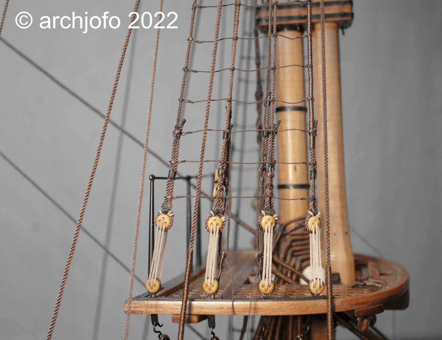
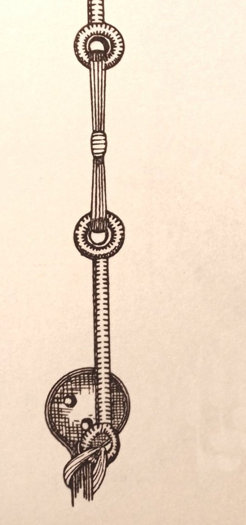
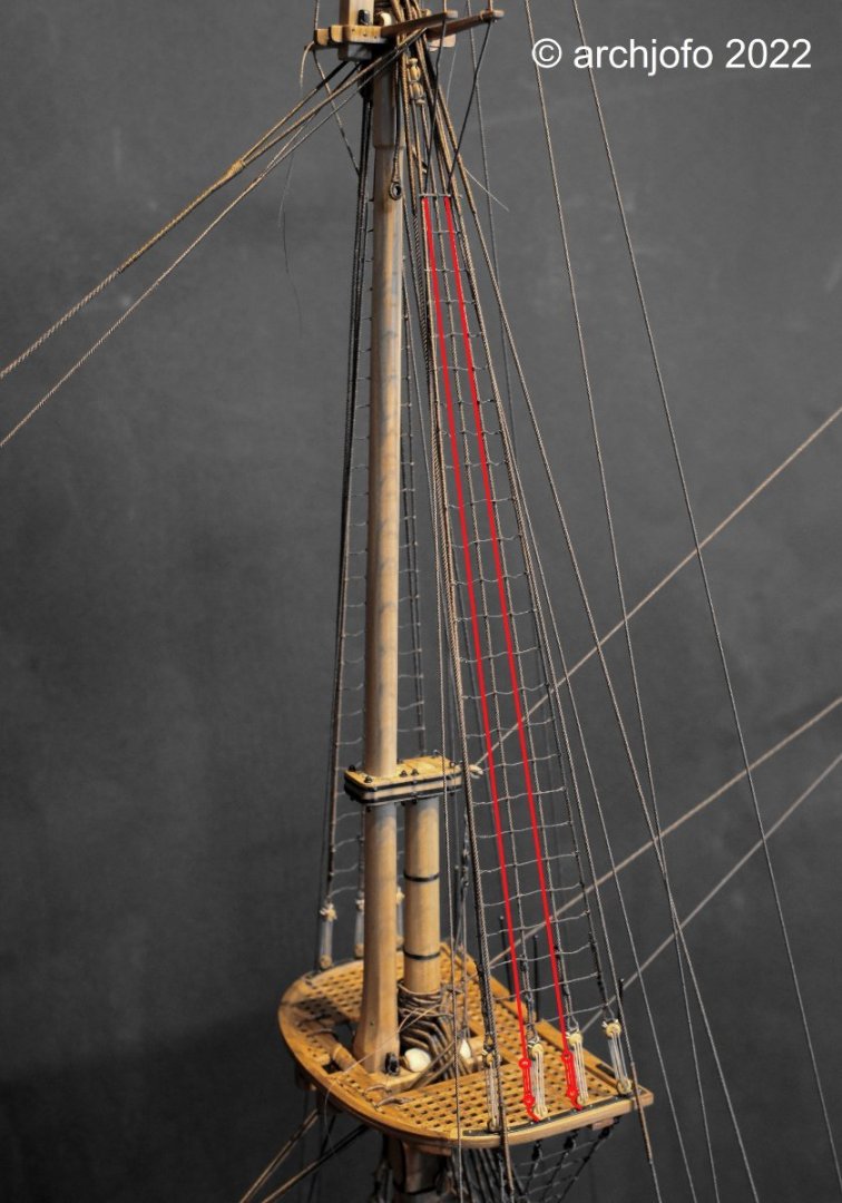
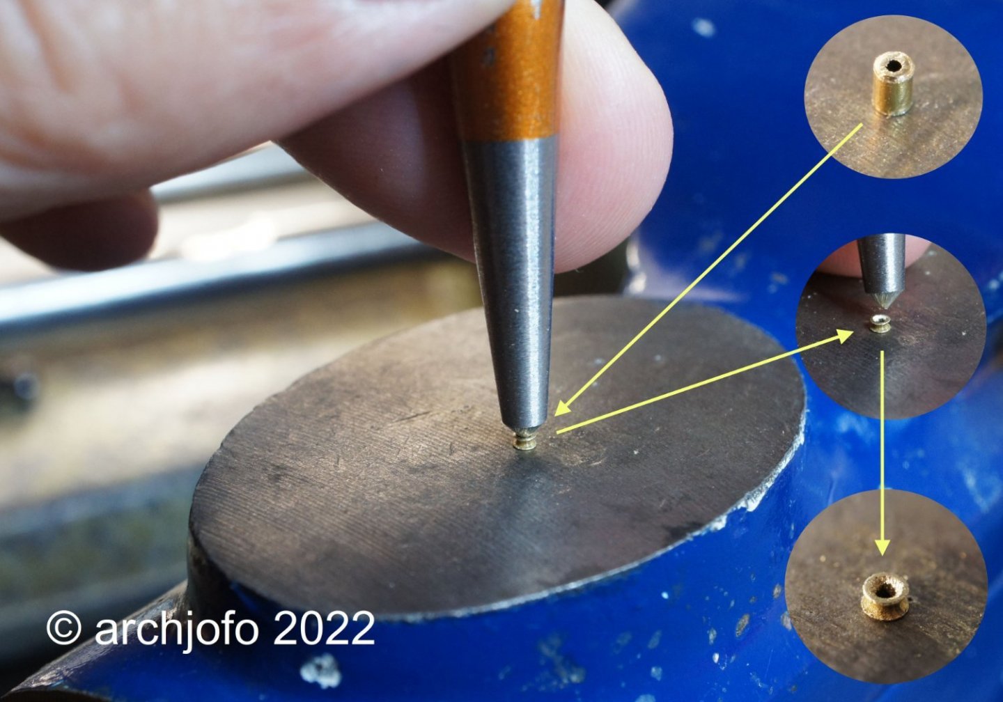
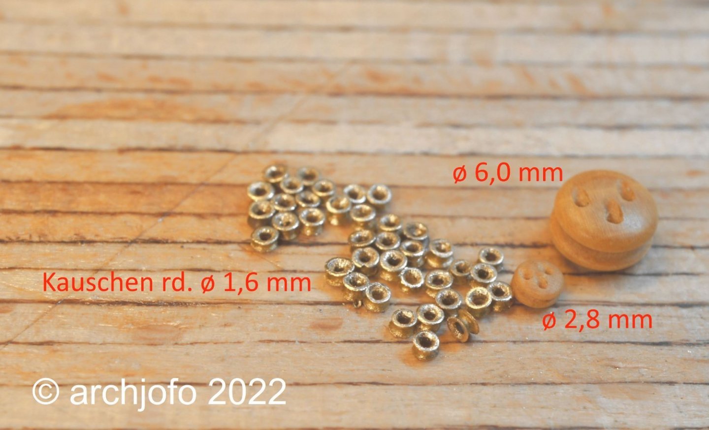
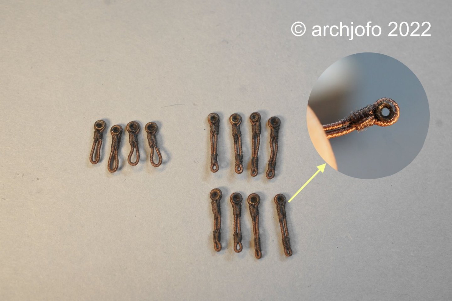
Fixing the topgallant shrouds A long time ago I dealt with this topic in more detail, but without any concrete result. However, I can no longer postpone the implementation of this detail. According to my research and a corresponding interpretation of the description in the monograph of La Créole, the topgallant shrouds are now fixed by lashings, which are attached to the fittings of the deadeyes. The respective lashing is made with thimbles. On the next picture I show the course of the topgallant shrouds using the main top as an example. So once again thimbles had to be made, 24 of them in total. In relation to the deadeyes, the thimbles should not be too big, of course. That's why I had to introduce another thimble size (ø 0.9 mm / ø 1.2 mm / ø 2.0 / ø 2.5 mm) in addition to the ones used for this model so far. For this purpose I bought brass tubes with a diameter of 1.0 mm, which finally resulted in thimbles with a diameter of about 1.6 mm. In the meantime I only make the thimbles with a suitable centre punch. With the cone-shaped point I form the tube section into a thimble with lightly dosed hammer strokes, as shown in the following picture. To make the strops for the lower thimbles I use served ropes with ø 0.35 mm. For tying to the fittings of the deadeyes, eyes are formed as shown in the drawing before. The last picture shows the finished strops, 4 x 3 pieces in total. The shorter strops are for the mizzen mast. I will report about the fixing of the topgallant shrouds on the model soon. To be continued ...
-
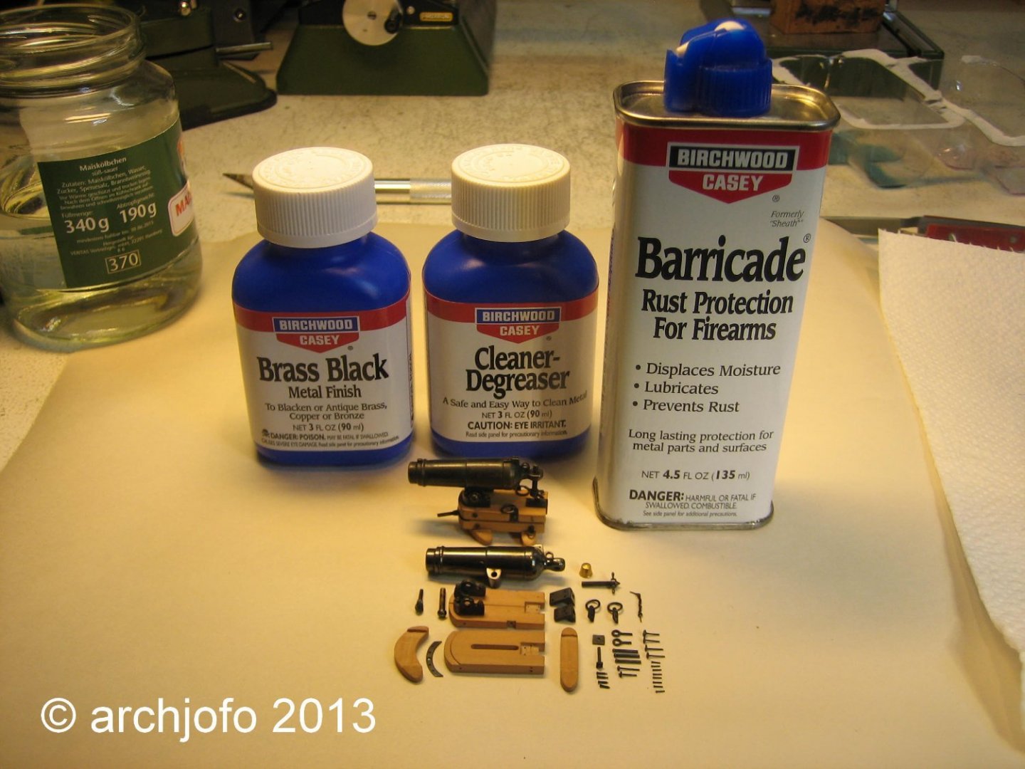
@GioMun Hello Gorgio, Thank you for your interest and appreciation of my work. As you can see in the picture below, I use these products for the brass parts.