


rvchima
-
Posts
678 -
Joined
-
Last visited
Content Type
Profiles
Forums
Gallery
Events
Posts posted by rvchima
-
-
Much Better!
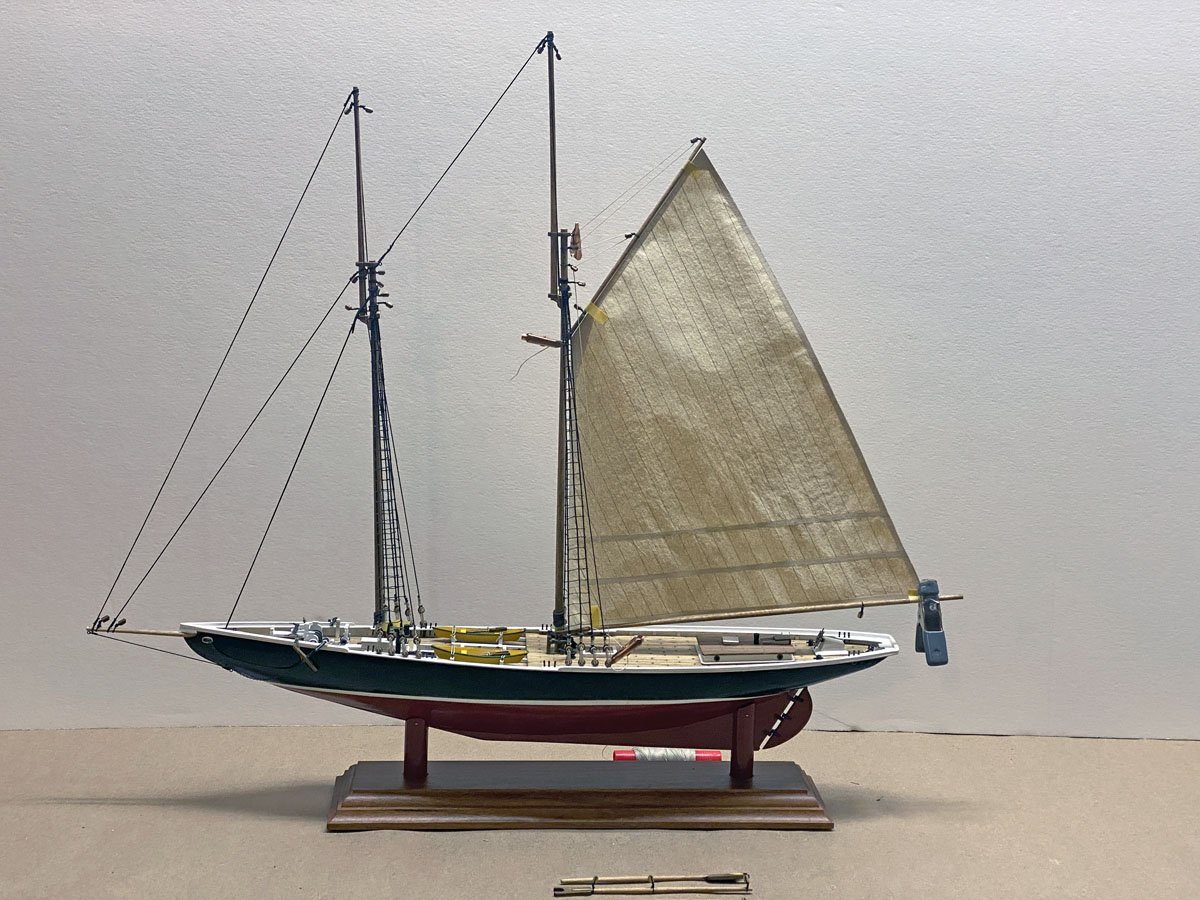
I built a new mainsail from silkspan using Tom Lauria's technique linked above. Tom does not seem to post on MSW but a quick search on Lauria turned up 6 pages of mentions, mostly about making sails or rope hanks.
I had plenty of silkspan from previous model airplane projects. It is strong and does not disintegrate in water - that's why it's also used to make teabags. It is available in three thicknesses from Sig Manufacturing.
Tom said his was .0015" thick. Mine is .003" thick - I suspect it's Sig's medium-weight material. My only concern is that silkspan can become brittle and yellow over the years. However, the first step of Tom's process is to coat the silkspan liberally with artists' acrylic paint, and that should help protect the material.
I chose an off-white paint called Titan Buff. I think it resembles muslin. I painted two sheets about 18" x 24" and used almost half a tube of paint! The silkspan really soaks it up. The paint goes right through the material, so when the front is done the back is too.
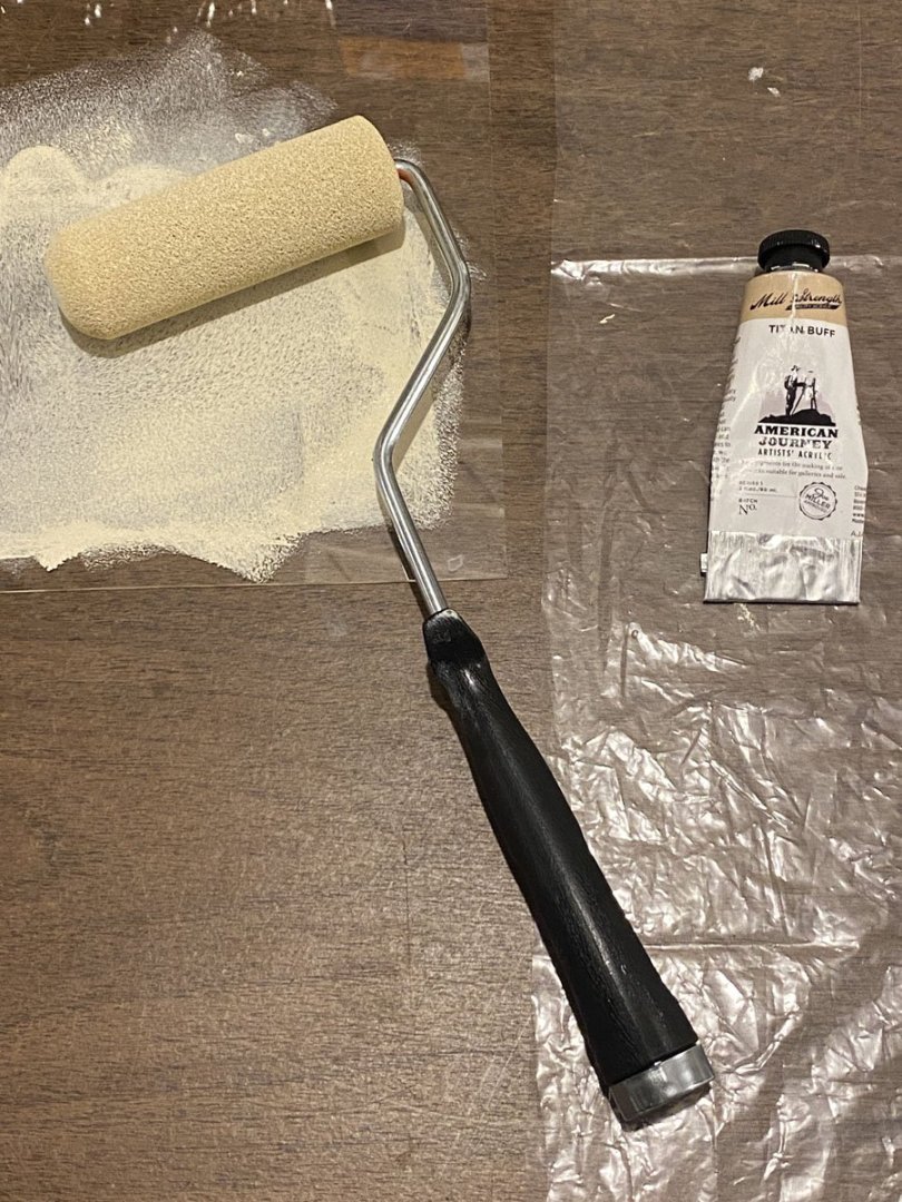
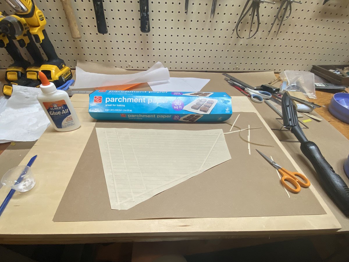
I marked the sails with a hard, dark pencil and attached hem reinforcements with diluted Elmer's glue. Tom recommends using a travel iron to seal the strips down, with a sheet of dry wax paper between the sail and the iron. Dry wax paper is NOT the wax paper you have in your kitchen. It is also called deli paper and has the wax embedded in the fibers so it doesn't come off on your sandwich or your sail. Even better, we had some parchment paper which is silicon-based and used for baking in a hot oven. I only needed a 6" strip.
I don't have a travel iron - I don't think I've ever ironed clothes while traveling. I do have a covering iron used to attach iron-on covering to larger model airplanes. I set it to 250 degrees and it worked perfectly.
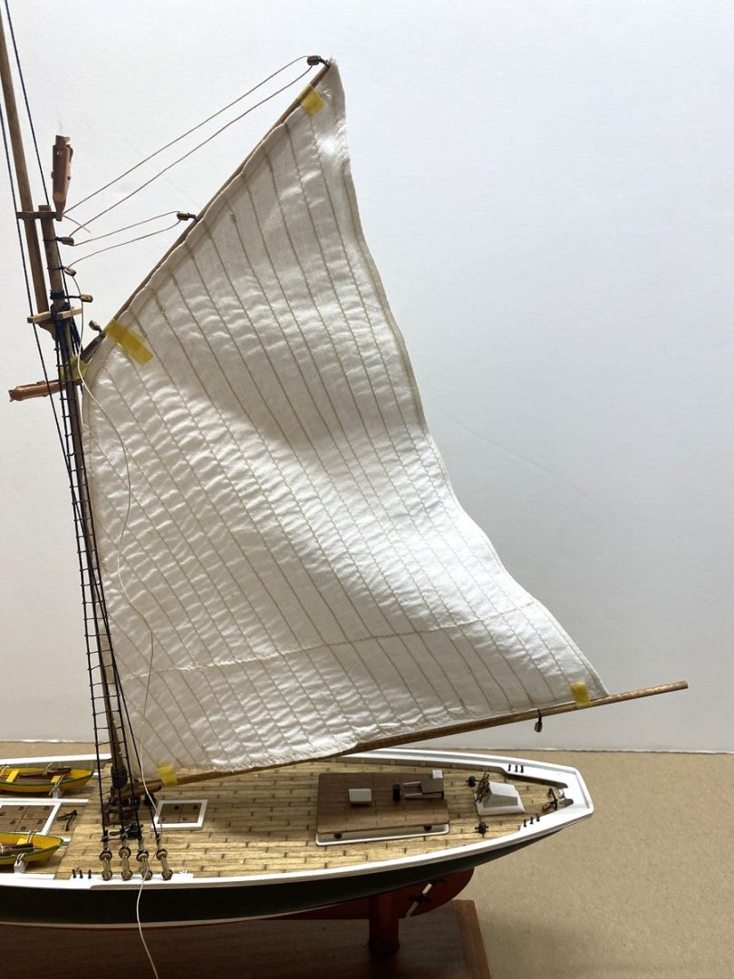
The mainsail took a few hours to make and I am pretty happy with it. I still have to stitch it to the boom and gaff, and attach the sail to the rings on the mast. That looks tricky.
-
Well, That's Not Going to Work
After all the sewing, my cloth mainsail is too far out of shape. I think I will try making sails out of silkspan, as described in this YouTube video by Tom Lauria. I actually have plenty of silkspan left over from my model airplane days.
Making Sails for Ship Models from Silkspan, Parts 1 & 2
-
Every Project Deserves a New Tool - Or Does It?
I was ready to start sewing sails, so I collected all my tools and materials from my basement workshop and carried everything to my wife's sewing room three flights up in the attic. We have an old Viking-Husqvarna sewing machine that we inherited from my mother-in-law 40 years ago. It used to do fancy stitches using various cams. The cam mechanism jammed years ago but it still did beautiful straight and zig-zag stitches, until earlier this summer when it started to smoke. We took it to a local repair shop where the repairman cleaned it and assured us that it was accumulated dust that was smoking.
I set up to sew my mainsail but when I went to wind a bobbin, the bobbin shaft disappeared inside the case. I spent all day disassembling the machine and managed to fix the bobbin shaft. I sewed two seams before the whole machine jammed up. I gave up and ordered a new Brother computerized sewing machine from Amazon. It cost less than what I paid the repairman for the other machine. It doesn't fit inside our old sewing machine cabinet but I think I can make it fit.
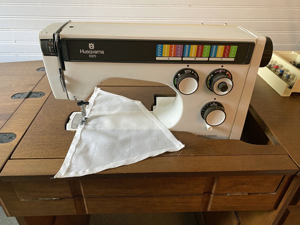
45+ year-old Viking-Husqvarna machine.
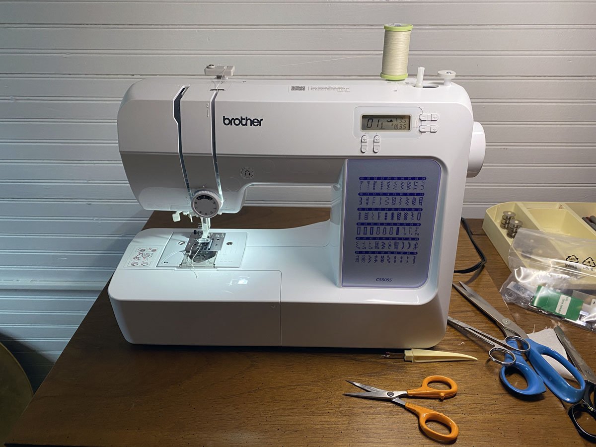
New Brother computerized machine. After a little practice on some scraps I stitched my mainsail.

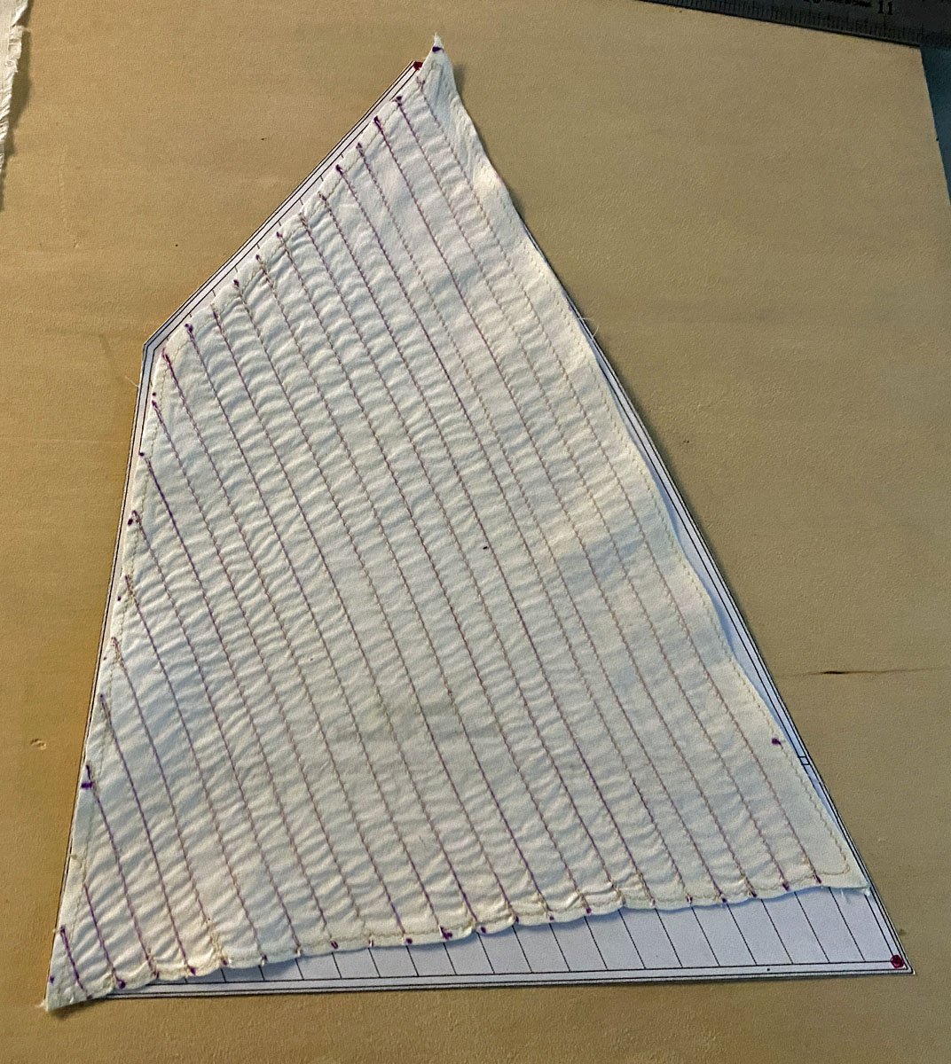
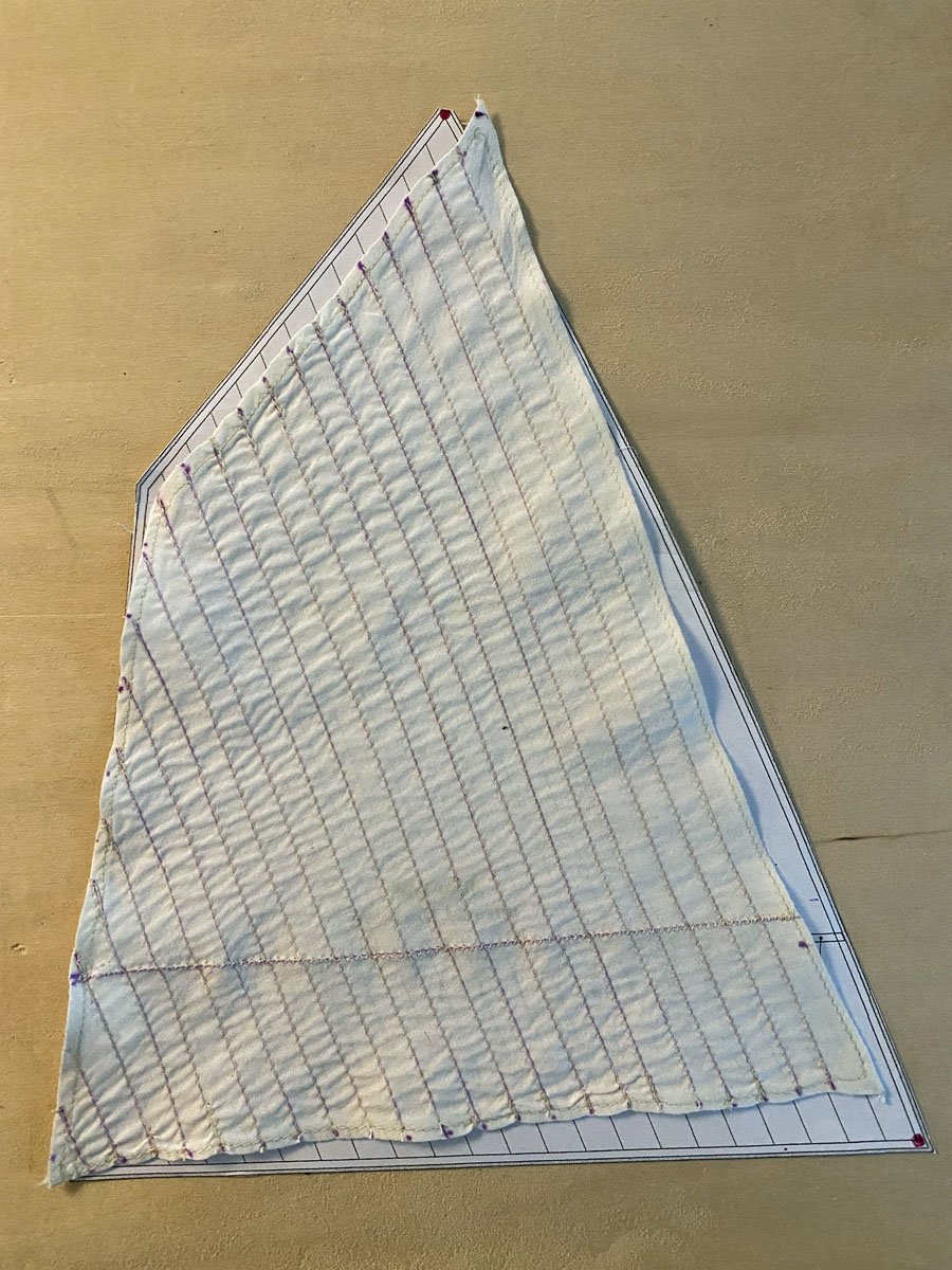
At first the sail matched my plan almost exactly. But after stitching all the scale seams between the individual pieces of fabric, the sail was much shorter than the pattern. (The purple stitch lines are supposed to disappear automatically after a few days.)

After stitching a zig-zaged reefing band the sail was also narrower than before. My wife said "Yeah, sewing can take up a lot of fabric."
By the way, I really like the computerized Brother machine. My only complaint is that there are a few settings that are made by shutting the machine off, holding a button down, and then turning the machine back on. But when you turn the machine off it resets the stitch pattern, width, and length back to the default. It's easy to get confused and end up with the wrong stitch. That never happened with the mechanical machine.
I don't know if I can use the sail or not. I'll have to try it on the ship and see how it looks. Amati was very stingy with their sail cloth and I don't have enough scraps to try over. Fabric is not so easy to find around here since JoAnn Fabrics went out of business. If I can find something appropriate, I could try sewing the fake seams on an extra large piece first, then cutting the sail slightly oversized and hemming the edges to fit the plan.
In a private conversation David Lester sent me information about making sails out of silkspan, a strong tissue that I used years ago for covering model airplanes. The seams can be drawn on it with pencil and the hems can be glued down. Maybe I should have listened to him in the first place.
-
Trevor,
Thank you so much for your comments about the alignment of the fabric on a sail. I know more about weaving than I do about sailing, so I really appreciate the help. As soon as I read
15 hours ago, Kenchington said:But a sail that has to stand up to the wind needs its free edges (i.e. ones not supported by a spar or stay) aligned to either warp or weft.
it made immediate sense. And good catch that the upper part of the "jib" sail has the cloth aligned incorrectly.
15 hours ago, Kenchington said:the one labelled just "jib" has one part with cloths aligned to the luff: Bad mistake by the kit manufacturer!
I am trying to be polite to Amati, but I am not too impressed with this kit.
I will experiment with the mitre joint on the two jib sails. I'm mot sure if I can sew it at this small scale but I will see what I can do.
- GGibson, king derelict and Kenchington
-
 3
3
-
Paper Sails
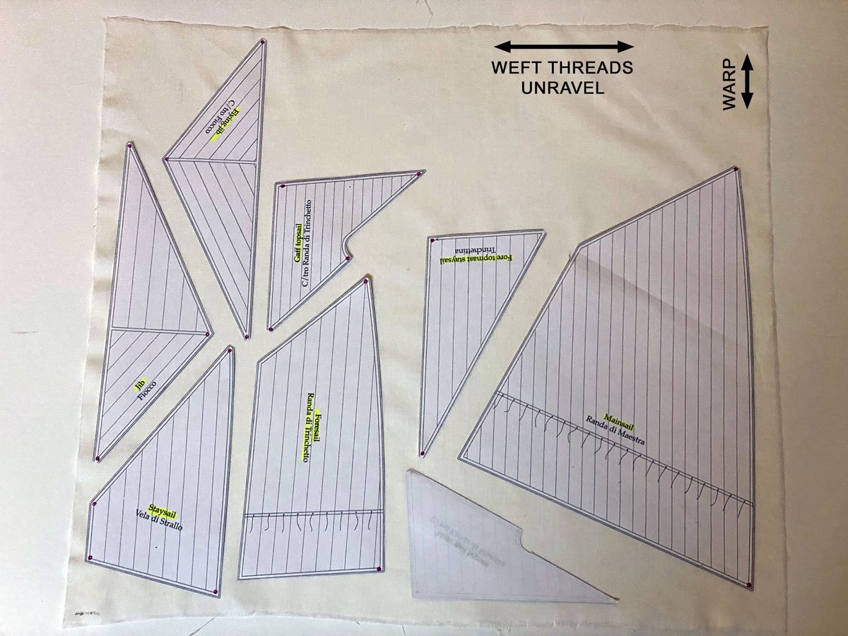
Yesterday I scanned and printed all my sail patterns. It took a little origami to fit each sail in my 8.5 x 11 printer, and I had to print the main sail in two pieces.
Today I washed and ironed the cotton fabric that came with the kit, then laid out the sails on it. Two sides of the fabric unravels - that's the weft. The warp goes in the other direction. The seam lines on the sails follow the warp, and I laid out the sails that way. It probably doesn't matter.
After reading Gregg's advice above I decided to test fit the paper sails. I'm really glad that I did because
1. Now I know where the sails go.
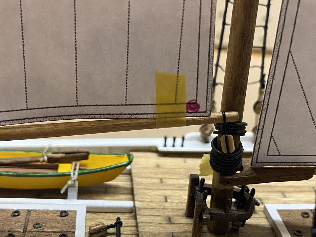
2. The foremast boom is too long.
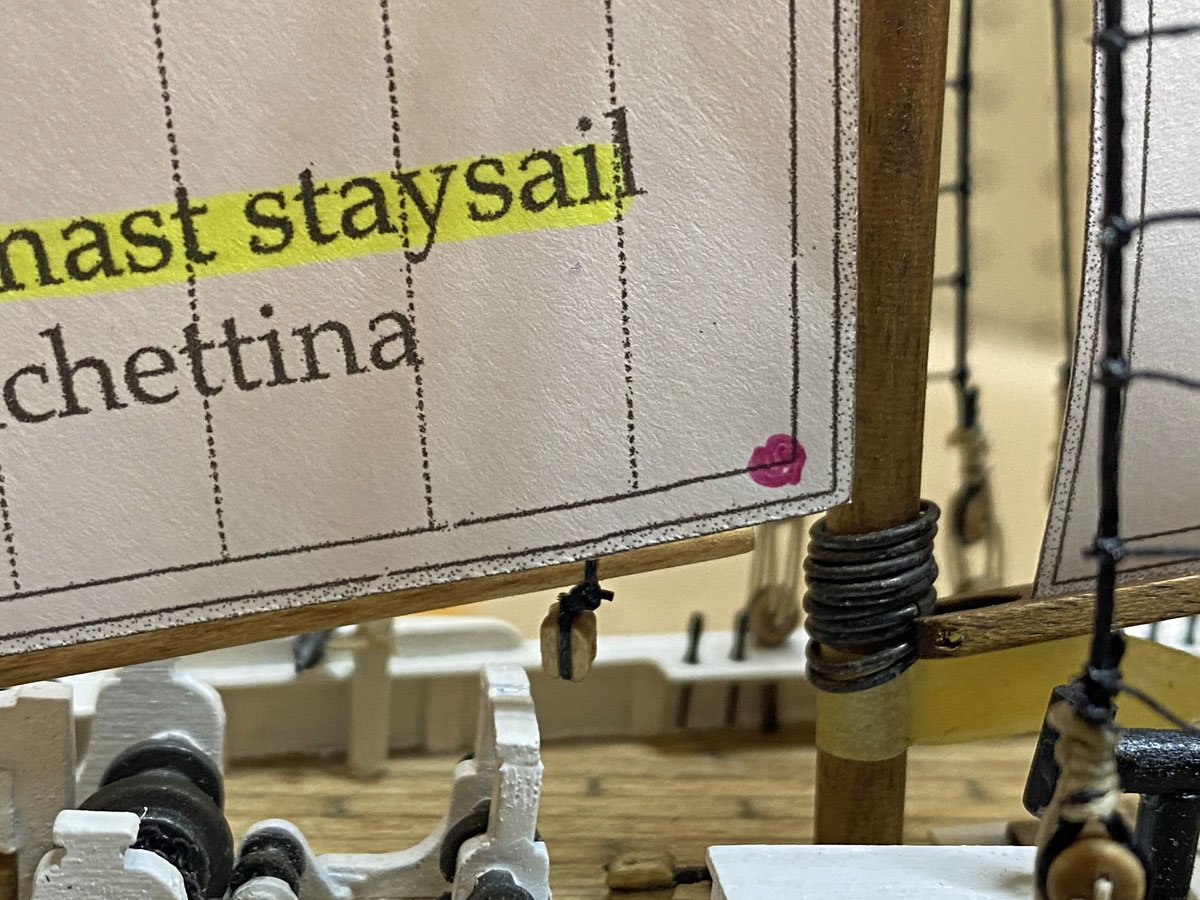
3. The foremast staysail pattern is too big.
After a couple of quick modifications I'll be ready to start cutting cloth.
- GGibson, Knocklouder and king derelict
-
3
-
18 hours ago, GGibson said:
Do as much of the gaff & boom rigging and block preparation as you can off ship.
Gregg,
I've read that elsewhere but never really thought about it until you mentioned it. It suddenly makes a lot of sense. I can attach the booms, gaffs, and blocks to the sails off the ship, and then drop them in place. Thanks for the advice.
- Knocklouder and GGibson
-
2
-
Thank you everyone for all the compliments. After looking at several of the Model Shipways builds on MSW I am realizing that Amati left off a lot of details on this model. It still looks nice, but I do wish that I had gone with the Model Shipways kit.
Question
I am about ready to add sails. I suspect that the gaffs and booms should all be pinned to their respective masts. Is that right, or can I actually rig them in place?
-
Bowsprit with Blocks Re-positioned
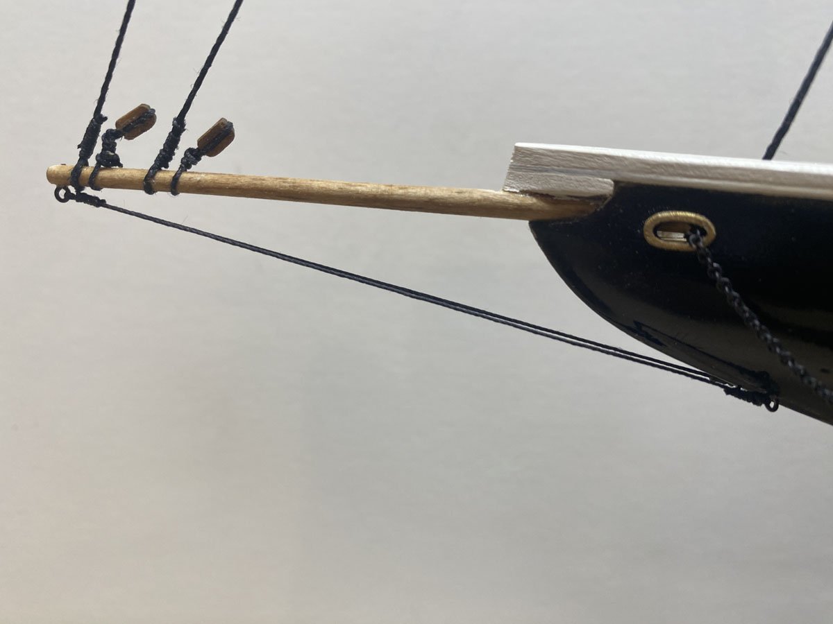
That looks a lot better. And 348 clove hitches later,
I can tell that it is going to be difficult to keep these skinny masts vertical while I attach the remaining standing rigging!
- David Lester, GGibson and Knocklouder
-
3
-
Poor Instructions and Plans
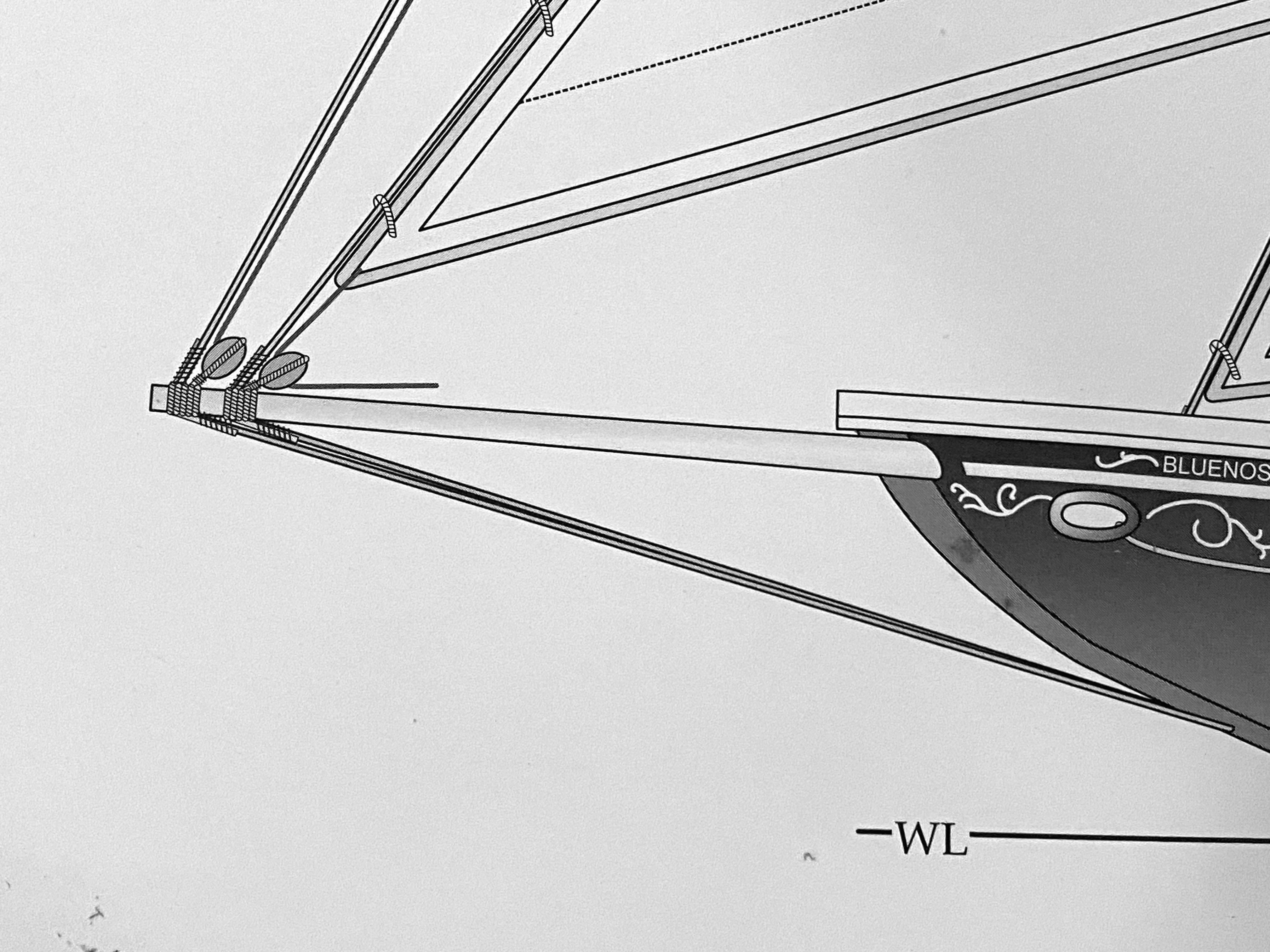
I made the bowsprit with two blocks attached to the end according to the instruction manual. I attached it and then noticed two lower stays on the plans. There was barely room to tie them on. Looking at other builds on MSW it is apparent that there should be several more stays below the bowsprit, but none are shown in the plans.
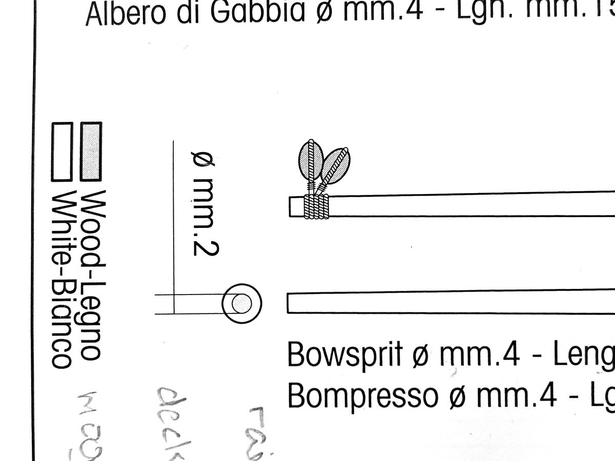
Bowsprit from the instruction manual.
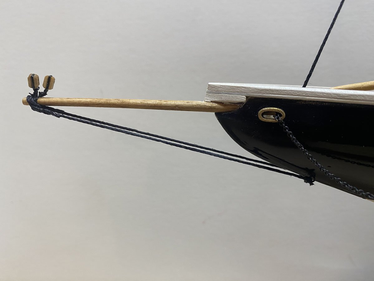
My current bowsprit with lower stays.
Now I realize that two stays for the jib and flying jib have to fit in there somewhere, and I won't have room. The plans show a little space between the blocks. The photo on the box shows even more space.
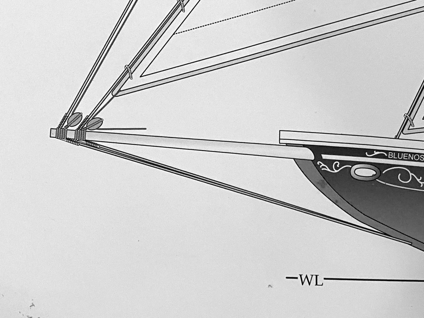
Bowsprit from the plans.
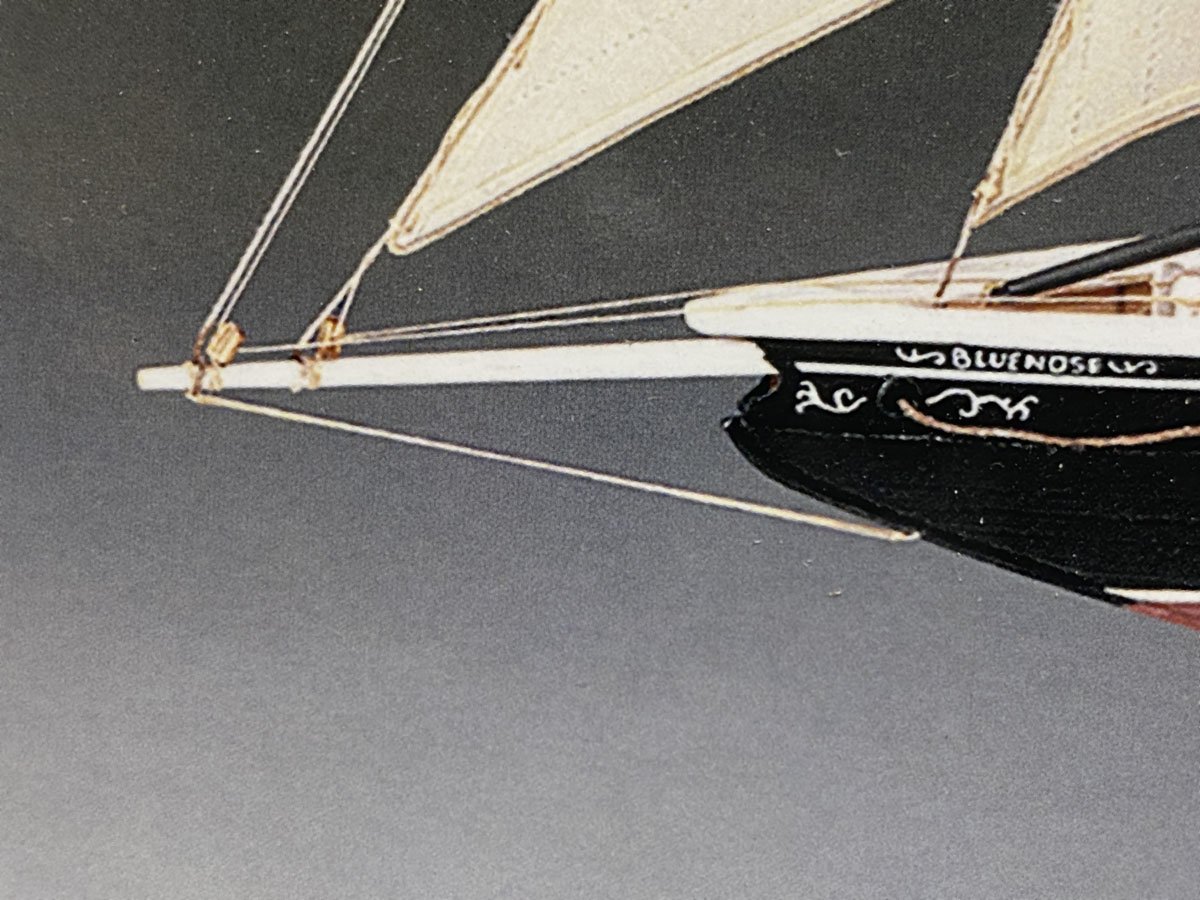
Bowsprit from the box cover.
It looks like I will have to do some deconstruction to move those blocks apart. I think I will also use some thinner line for the lower stays.
-
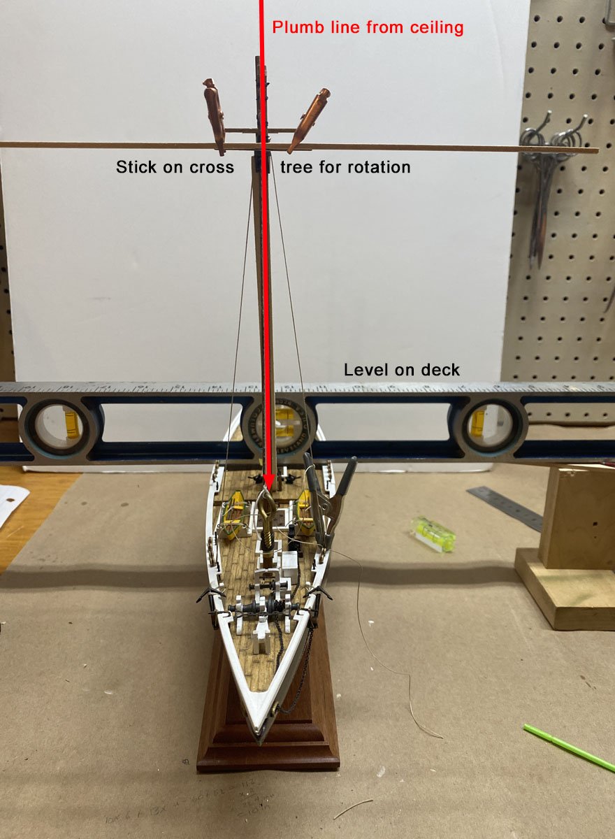
Stepping the Masts
The false keel in this kit is narrow and the slots for the masts and the holes in the deck were too big, so the masts would not stand upright on their own. I came up with a complicated way to set the masts vertical and hold them in place while I glued them.
- I hung a line from the ceiling with a screw eye weight to set the vertical.
- I put a heavy level across the deck, and braced it to hold the deck level.
- I attached a stick to the cross tree to visually set the rotation.
- I attached a line side-to-side across the cross tree and practiced tying it quickly.
When everything was ready I removed the mast, applied PVA glue, and put it all back together. It took a whole evening to step each mast. But they are vertical.

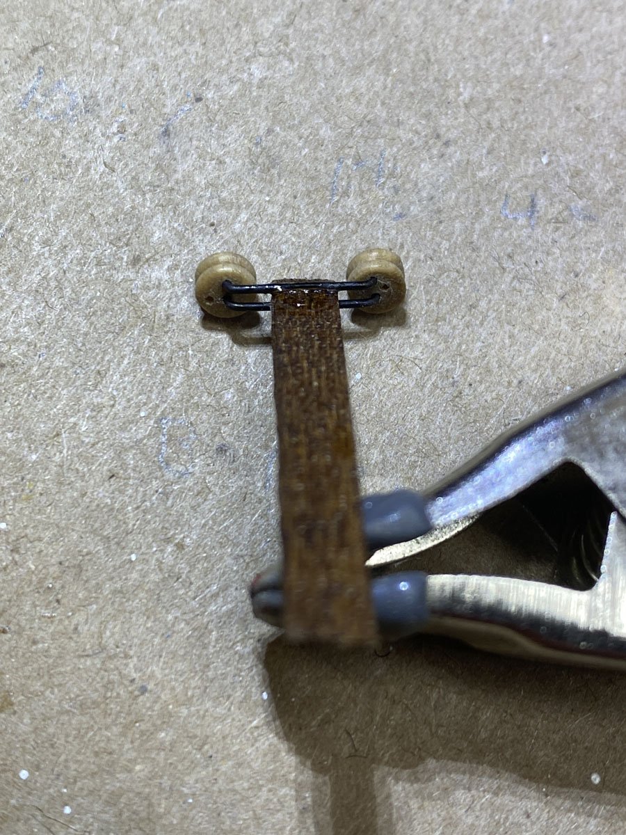
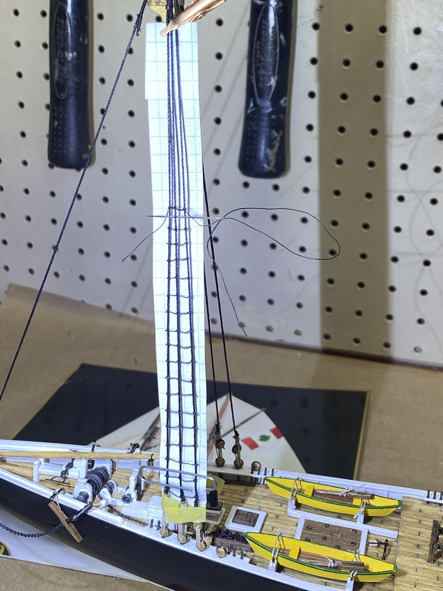
Attaching Deadeyes and Ratlines
I made a deadeye spacer from two butterfly pins and a scrap of wood as thick as the spacing between two holes on a deadeye. The photo shows how it works.


The mast stays are now attached and I am done with half of the ratlines. I worked for a fireworks company all through grad school, and everything was tied together with clove hitches - shell casings, fuses, lances on ground displays, etc. So I am very good at tying clove hitches, and the ratlines are coming along quickly.

The Amati kit comes with two spools of line, thick and thin, and both tan. I will use the thin for running rigging but am using other black line that I have for the standing rigging.
- Knocklouder and David Lester
-
2
-
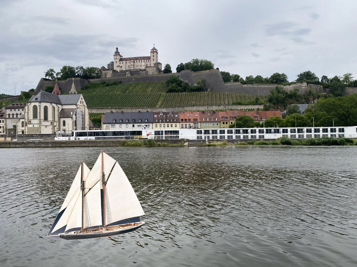
Viking Cruise Lines River Ship vs. Bluenose
In early July my wife and I took a cruise on the Main river through Germany on Viking Cruise Lines. They have 76 longships, all 443 ft long. The Bluenose was 143 ft long. Here is what it would look like next to our ship docked in Würzburg, Germany. It would not fit under the bridges!
-
On 7/28/2025 at 6:23 PM, Snug Harbor Johnny said:
1:100 is a relatively small scale to work in (as it tests my skills)
That's for sure! After looking at some of the 1:64 Model Shipways Bluenose builds I've realized that Amati just left off a LOT of small details on this kit. I'm kind of sorry I didn't go with the larger model.
-
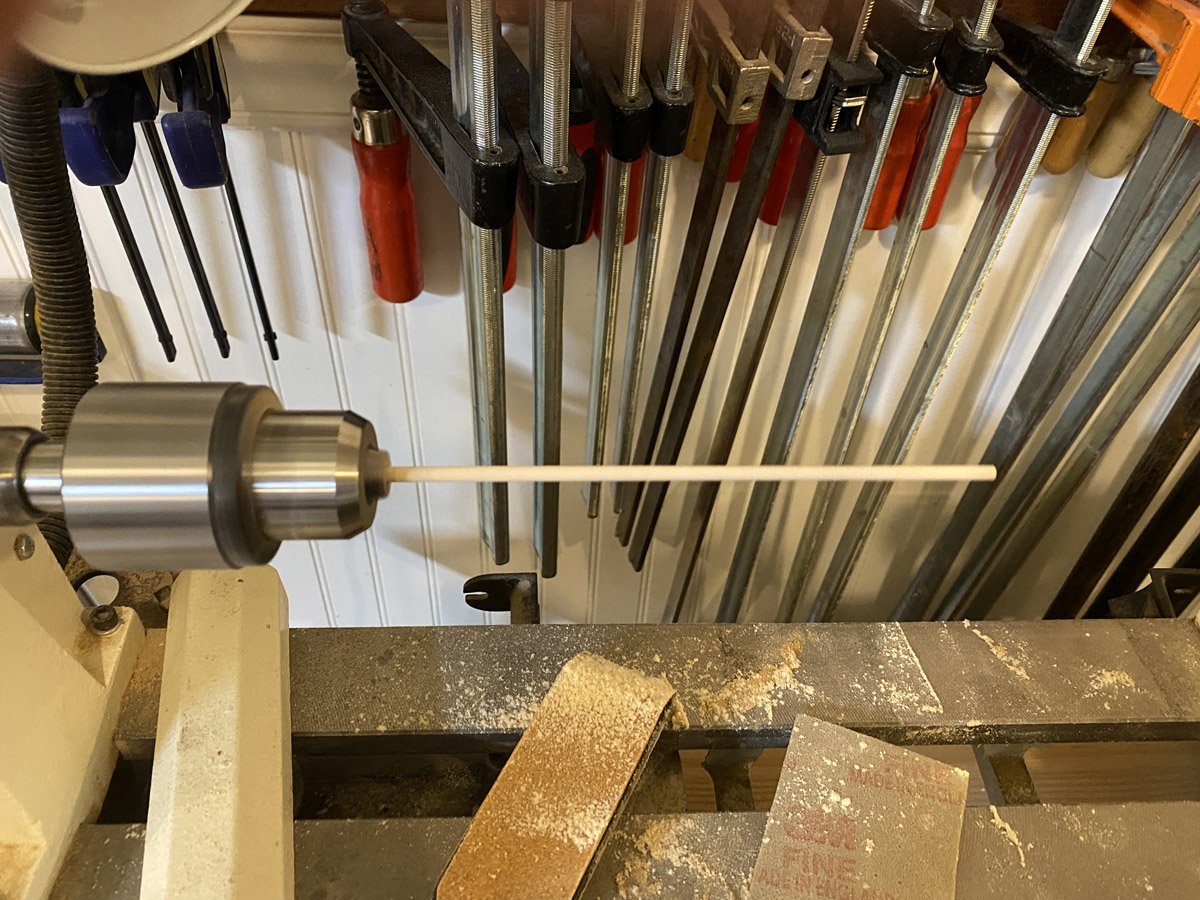
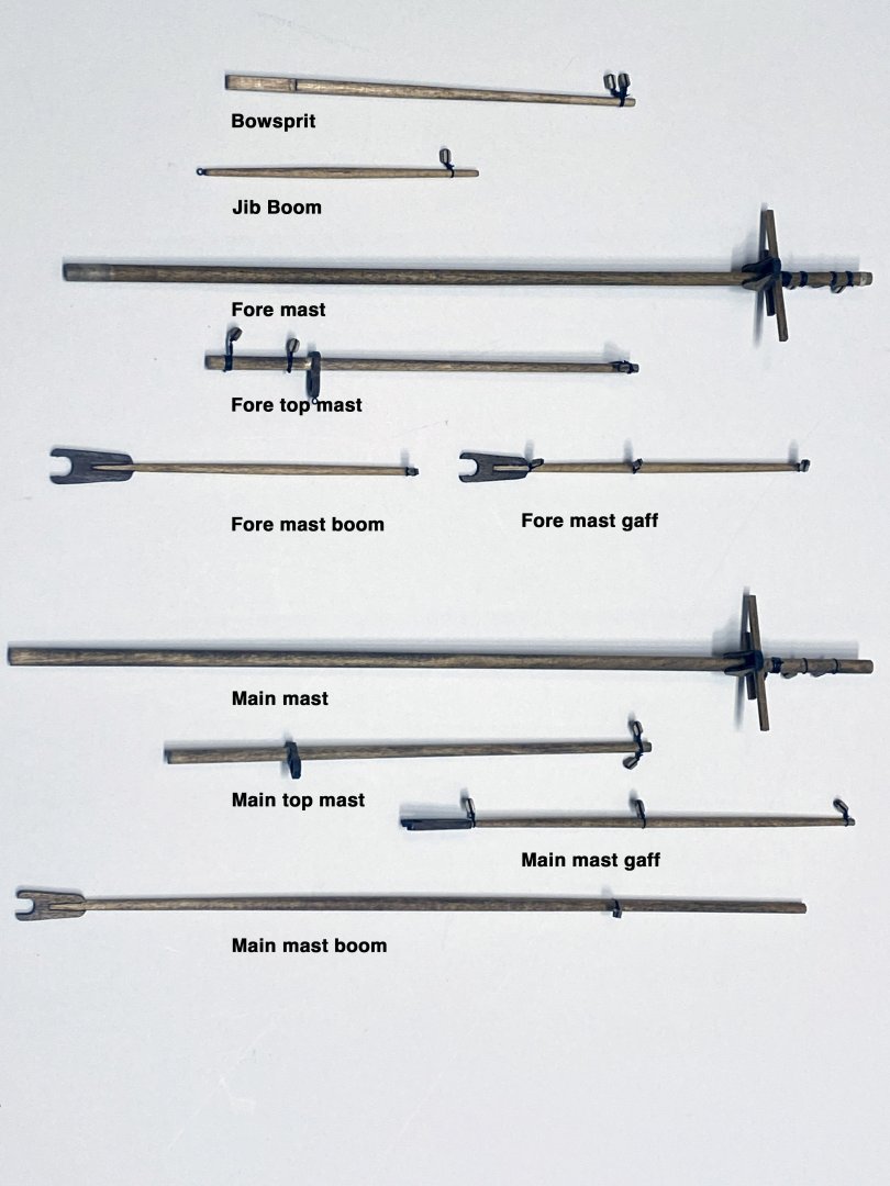
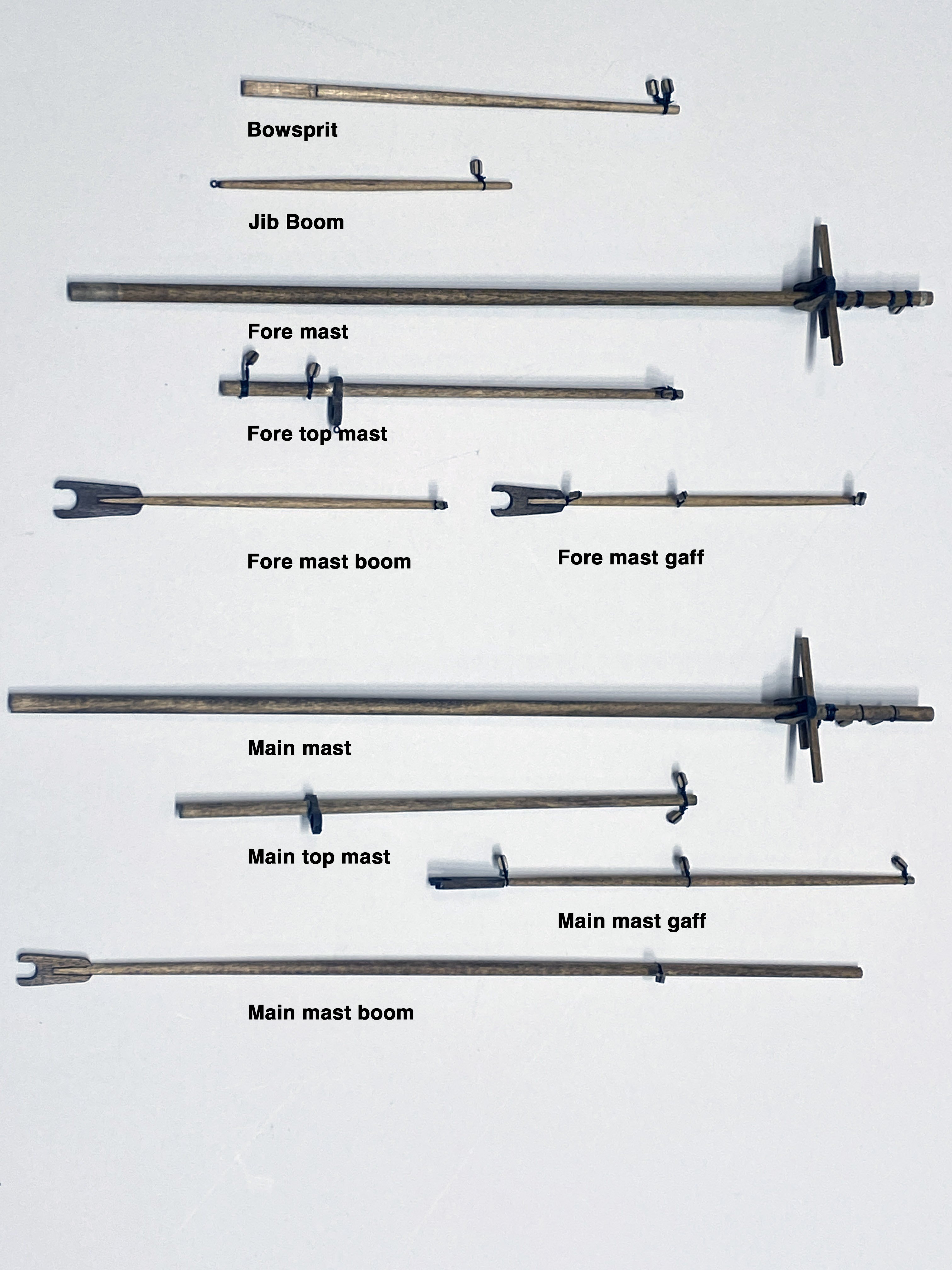
Masts, Gaffs, and Booms
I tapered the masts, etc. chucked on a lathe using sand paper. At first I struggled with how to seize a line to a block and attach it to a mast, until I remembered that I had posted a very simple way to do that under my Endeavour build. It's cheating but it looks fine, goes fast, and hardly wastes any line. All those pieces are done and ready to install.
- Knocklouder, bhermann and David Lester
-
3
-
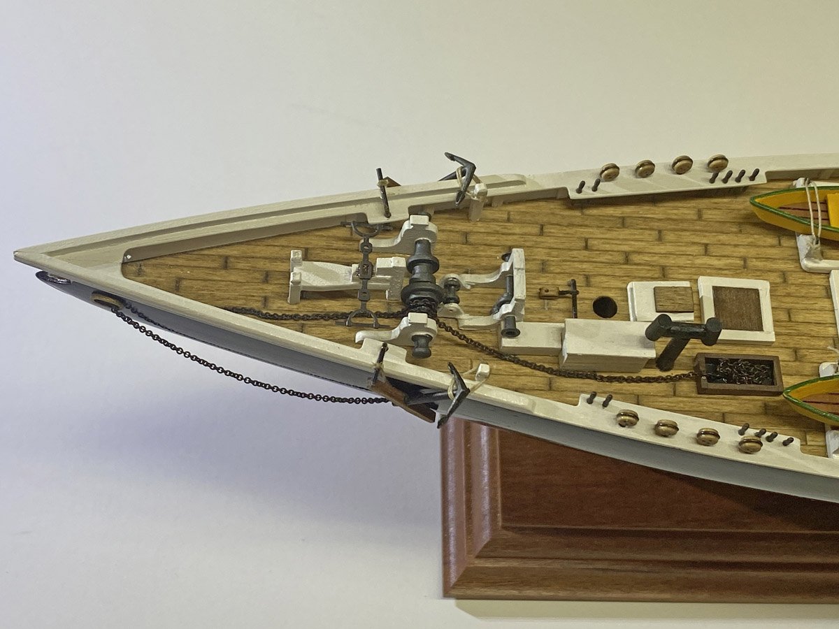
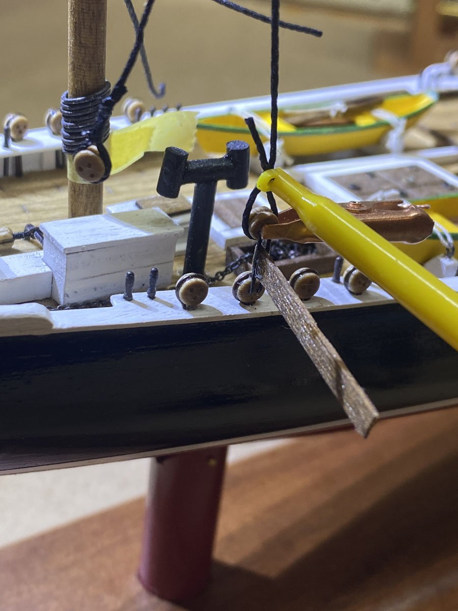
Anchors
The Amati kit came with two cast anchors but no stocks or chain. I made stocks from some scrap walnut, and I had a long piece of brass chain that I blackened. The instructions show the anchor tied to the cathead by the shank, and a rope from the ring to the hawsepipe, where it disappears. I searched several Bluenose builds on MSW and saw chains leading to the winch, around the engine box, and into a chain box (or possibly into a locker below the deck?) I made something like what GGibson shows in this post.
On 7/26/2025 at 6:42 PM, GGibson said: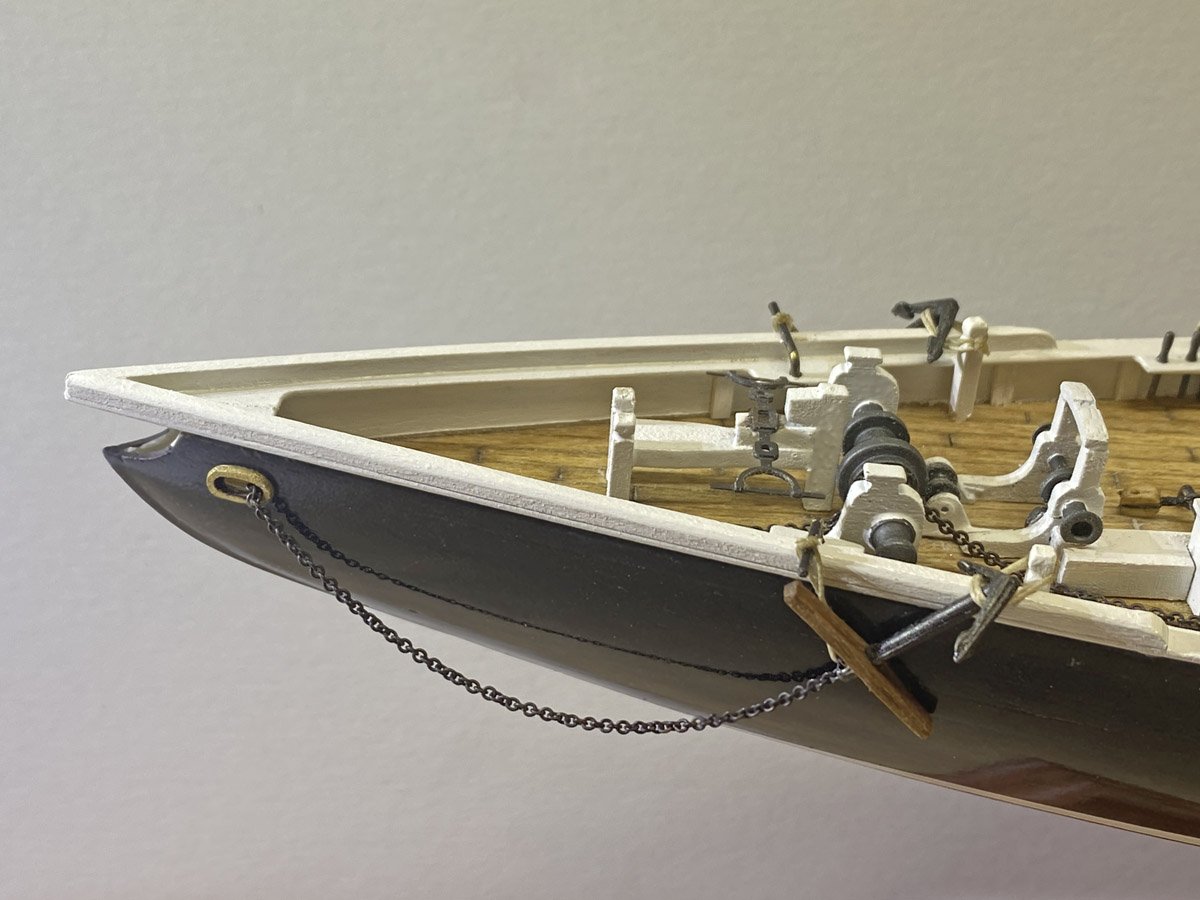
- Knocklouder, bhermann, David Lester and 2 others
-
5
-
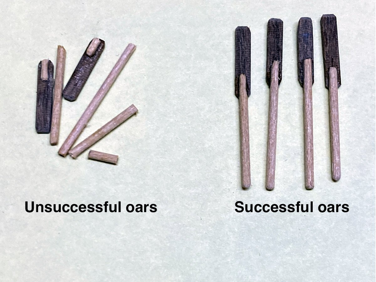
Dories - 13 hours over 4 days
The dories are made of 4 pieces of laser cut plywood assembled over a 4-piece form. The actual construction was pretty simple but I added some details that took a lot longer. Like these oars. They're 25 mm long and the handles are 1 mm dowel. They tended to break where the handles attach to the blades.
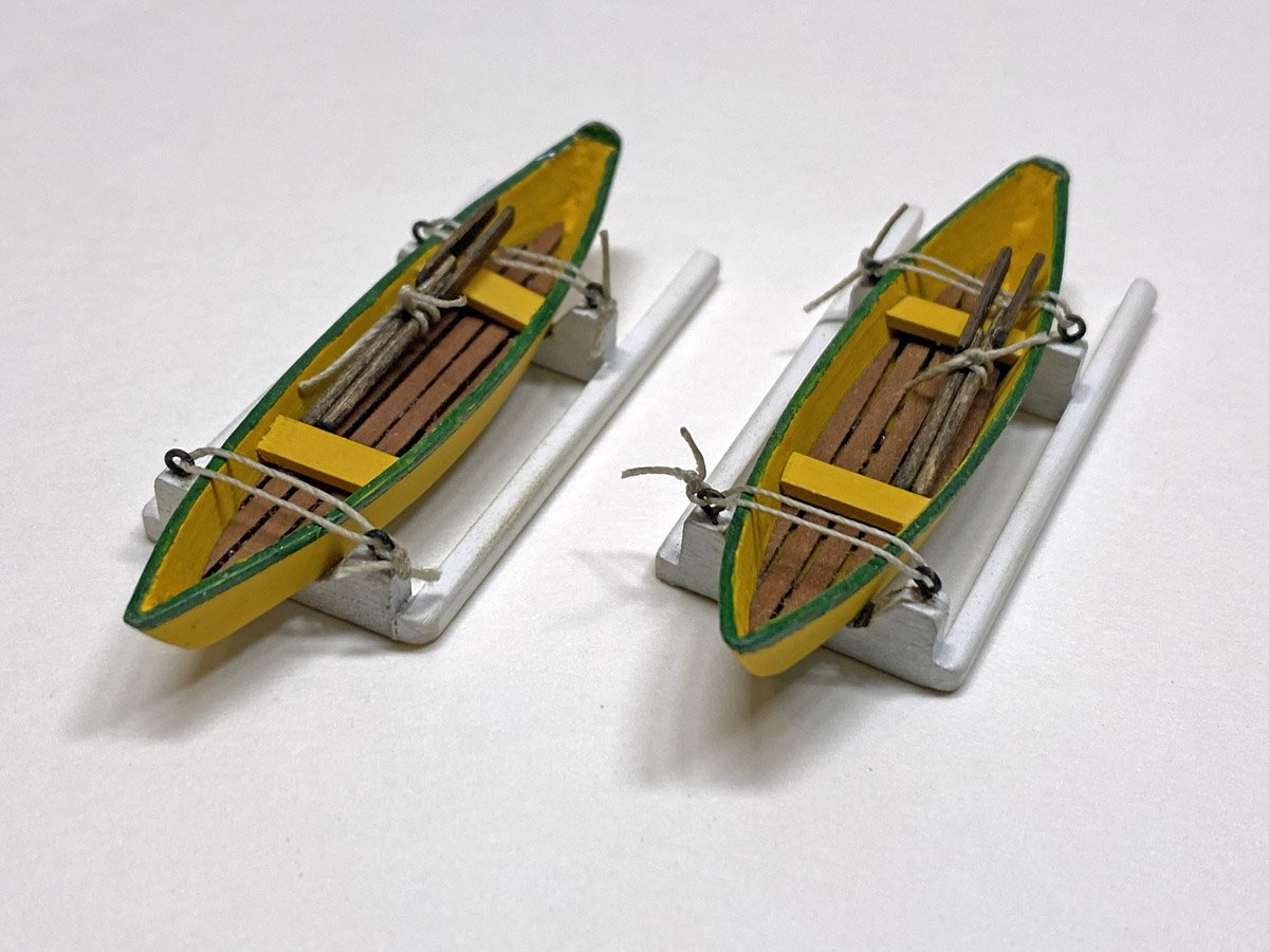
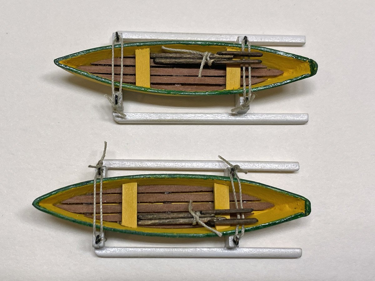
The floorboards are thin walnut strips. The spacing between the strips is exactly the size of my push pins.
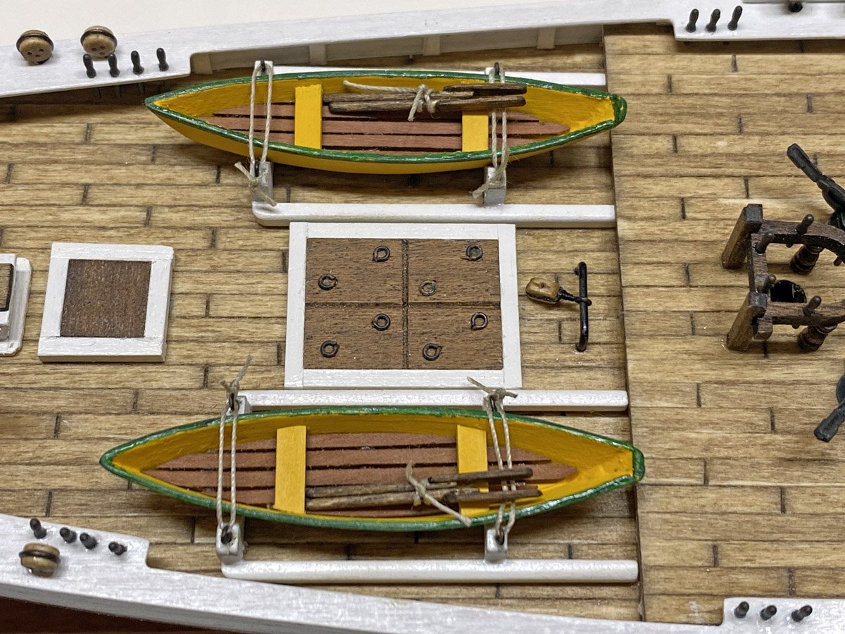
I attempted to paint the dories by hand to avoid setting up my airbrush. When they still looked uneven after 7 coats of Model Master insignia yellow acrylic, I got out my airbrush. In 10 minutes they looked great. The green was masked off but drawn with a permanent marker.
The Bluenose often sailed with 12 dories stacked 6 high. but 2 was enough for me.
-
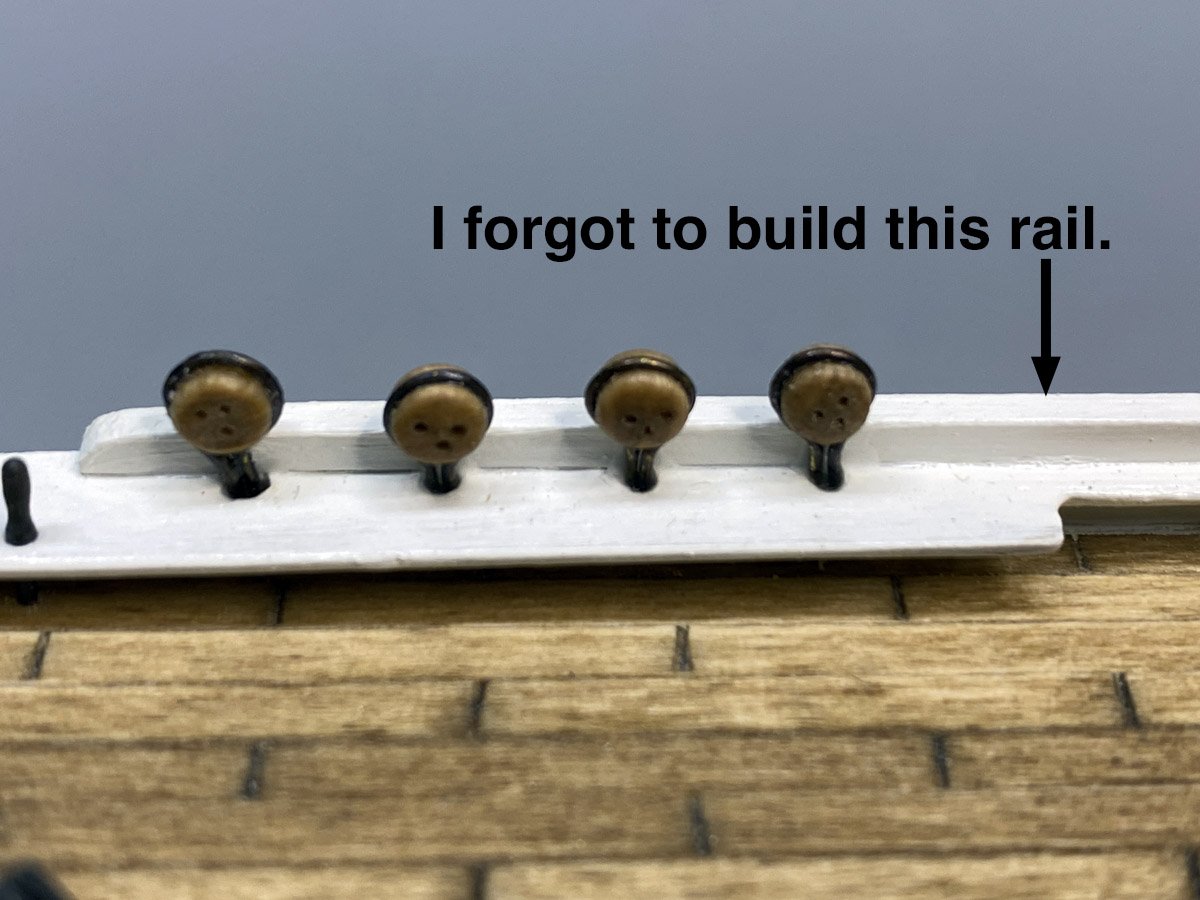
Oops, Missing Rail
I've been working on hatches, cabins, etc. and realized that I had neglected to add a second layer of railing around much of the hull. It wasn't hard to add, except where it interfered with 8 deadeyes amid ship. I had to wiggle them all loose, add the railing, paint it, and replace the deadeyes.
Hatches, Cabins, etc.
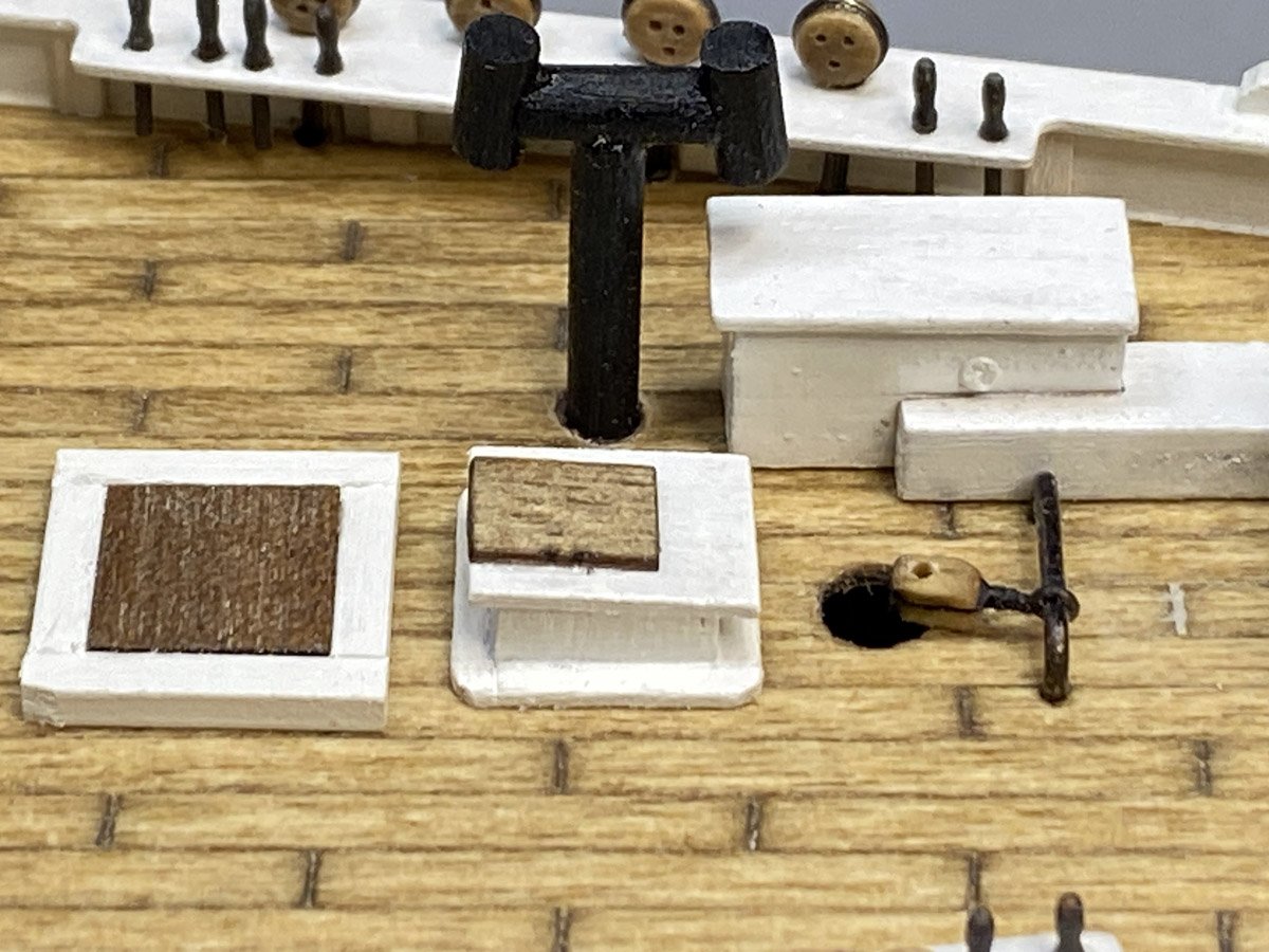
The tiny cabin is about the size of a Monopoly house and difficult to hold while working.
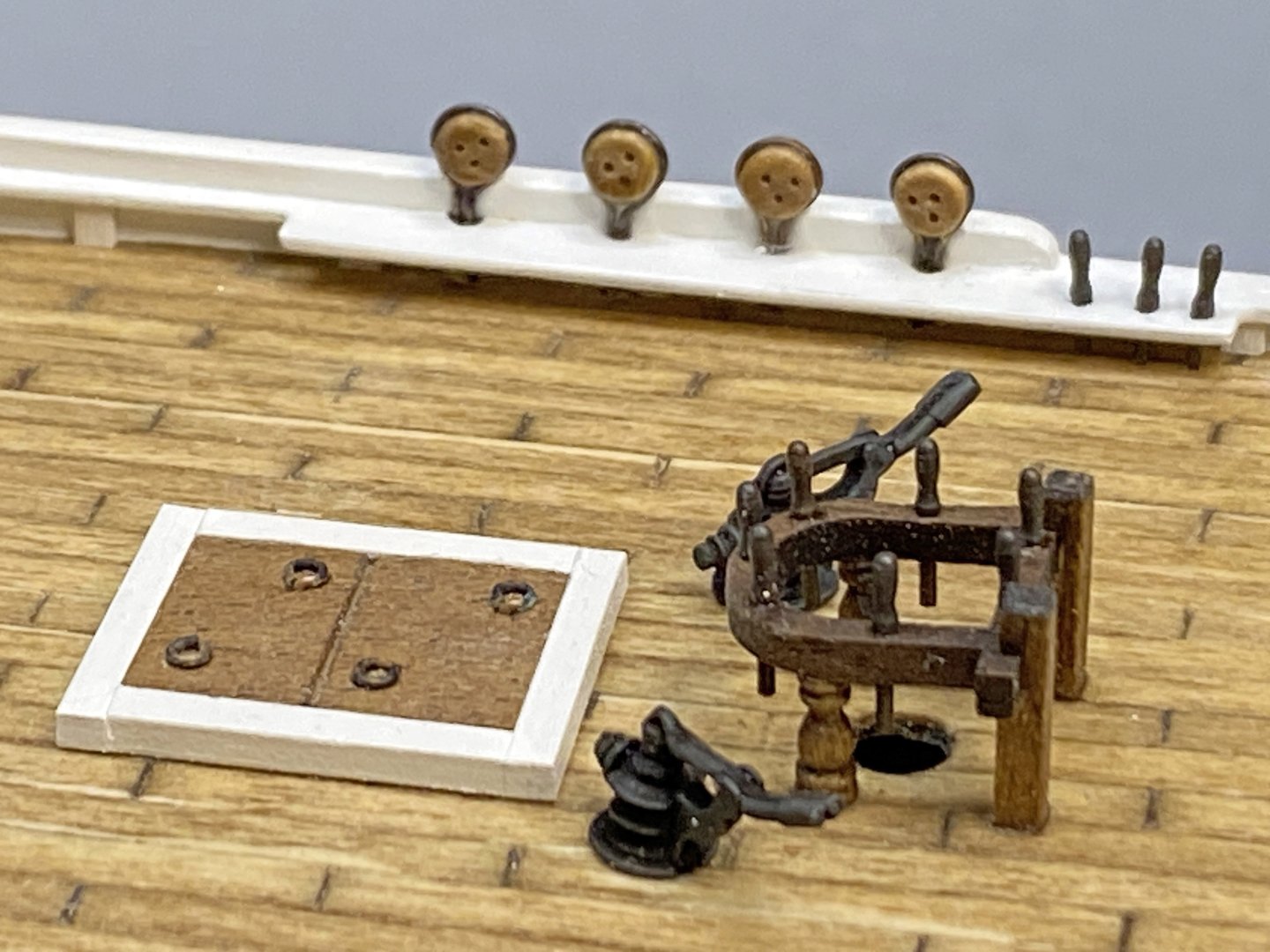
The rings on the hatches are actually eye bolts folded 90 degrees and glued in holes. I did find some belaying pins. They are a bit long where the railing is a bit low, so I will have to improvise when tying lines to them.
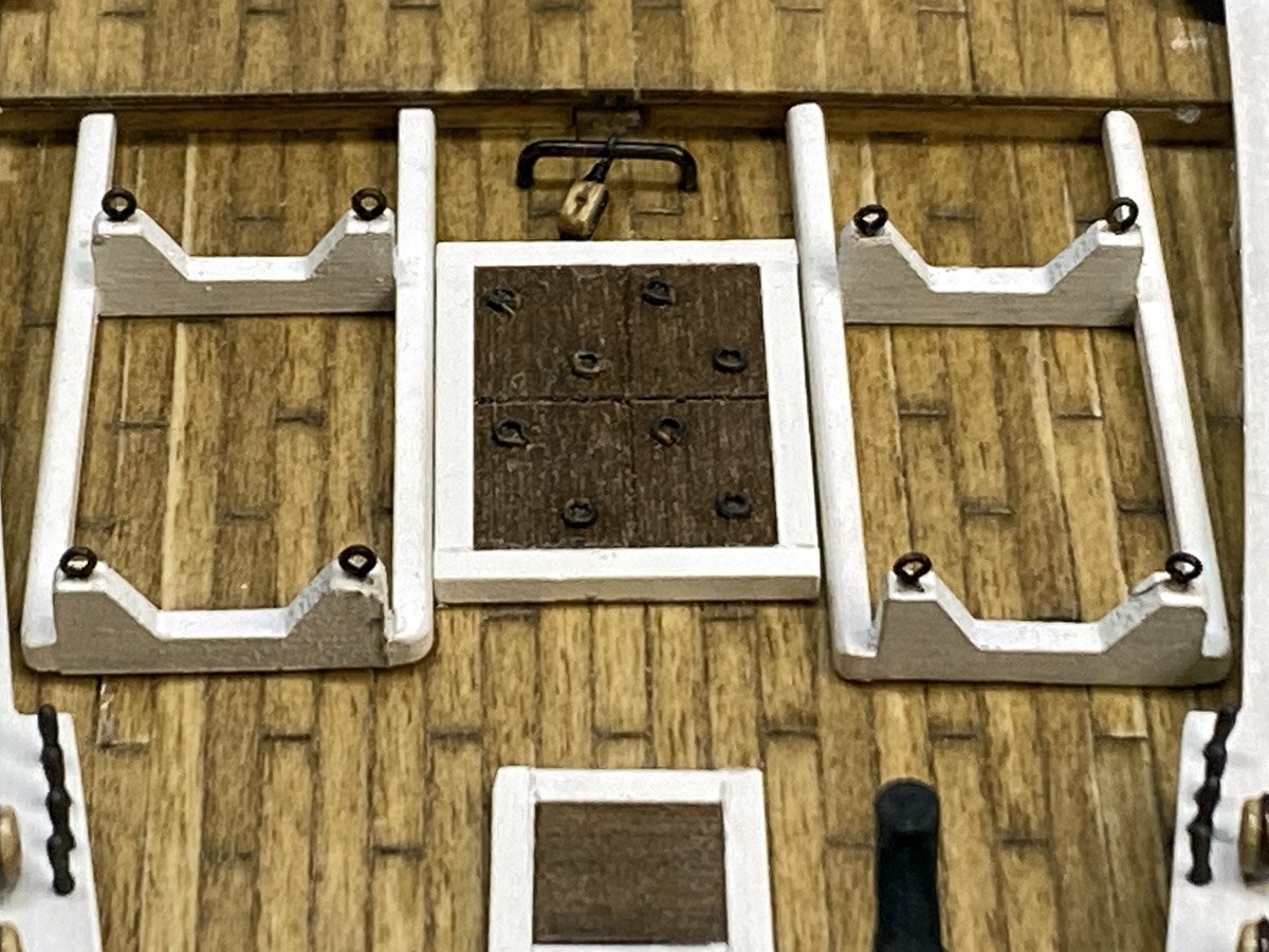
Main hatch and dory racks. The dories are built and currently being painted.
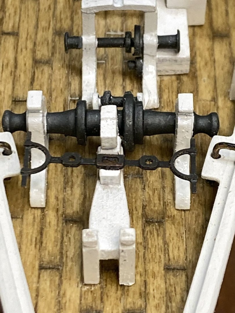
The winch was made from several random pieces - aluminum tube, tiny round disks, 2 cast metal pieces, 2 turned brass pieces, and a piece of photo etched brass.
- RVB, Scott Crouse, king derelict and 2 others
-
4
-
 1
1
-
Back to Work
I just returned from two weeks in Europe, traveling from Prague to Paris mostly on a river cruise. After mowing the grass I got back to work on the Bluenose.
The Amati kit comes with a fairly ugly stand so I spent the last couple of days making a nice one out of cherry. I shaped dowels to make the pedestals.

Old stand
New stand

The instructions say to wrap the deadeyes with fine brass wire. That seems simple enough but it took a few tries to get the hang of it. I darkened the wire with Novocan brand patina for stained glass.

The wires go through the rails and into the deck, and are attached with CA. The remaining holes are for the ropes, but there are no belaying pins with the kit! The instructions just say to run the ropes to the appropriate holes. I hope I have some belaying pins in my spares box.
-
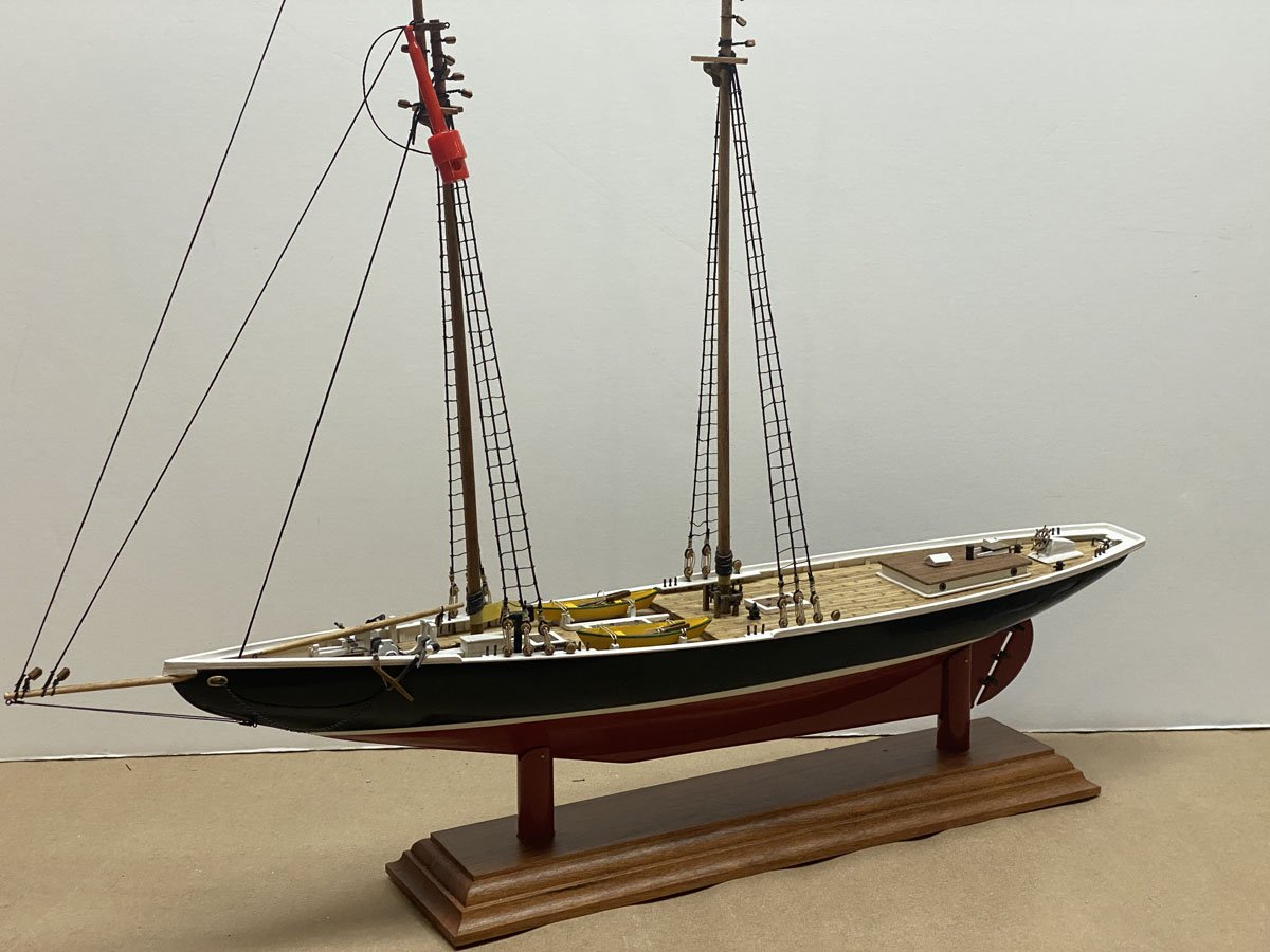
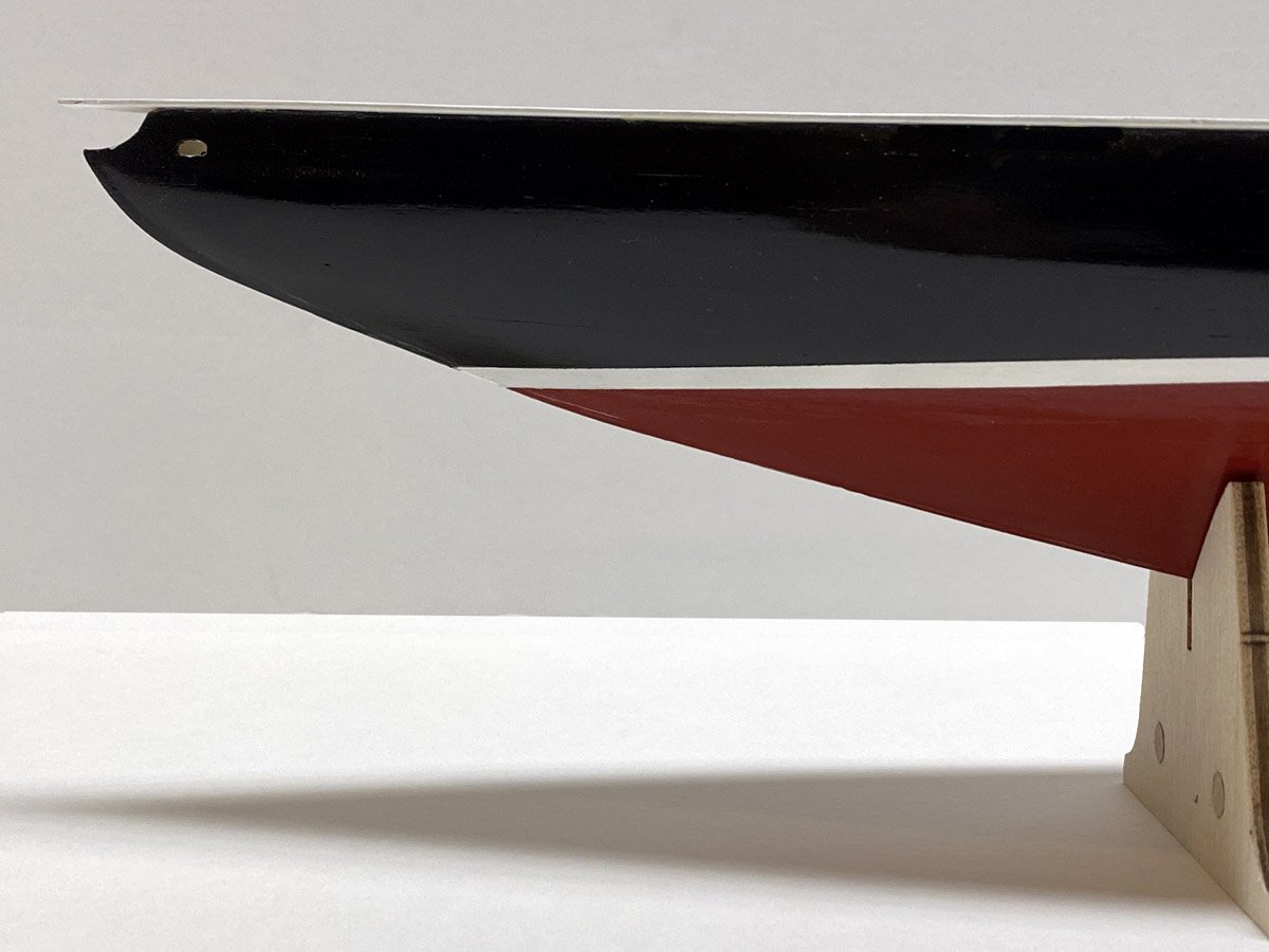
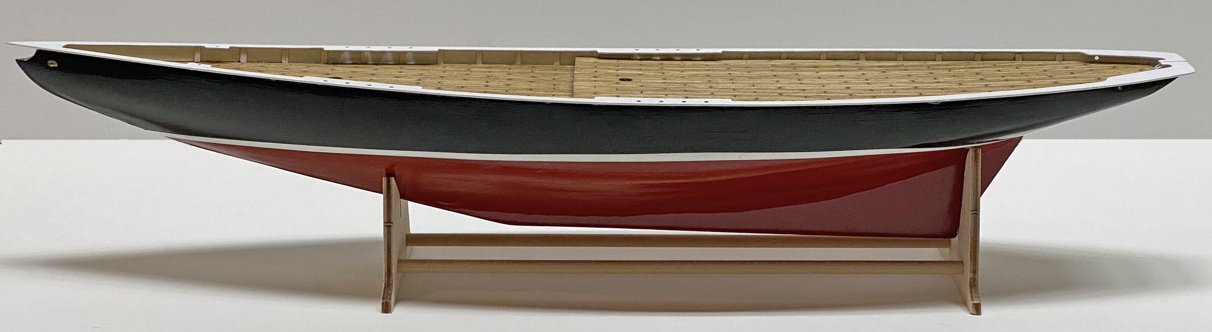
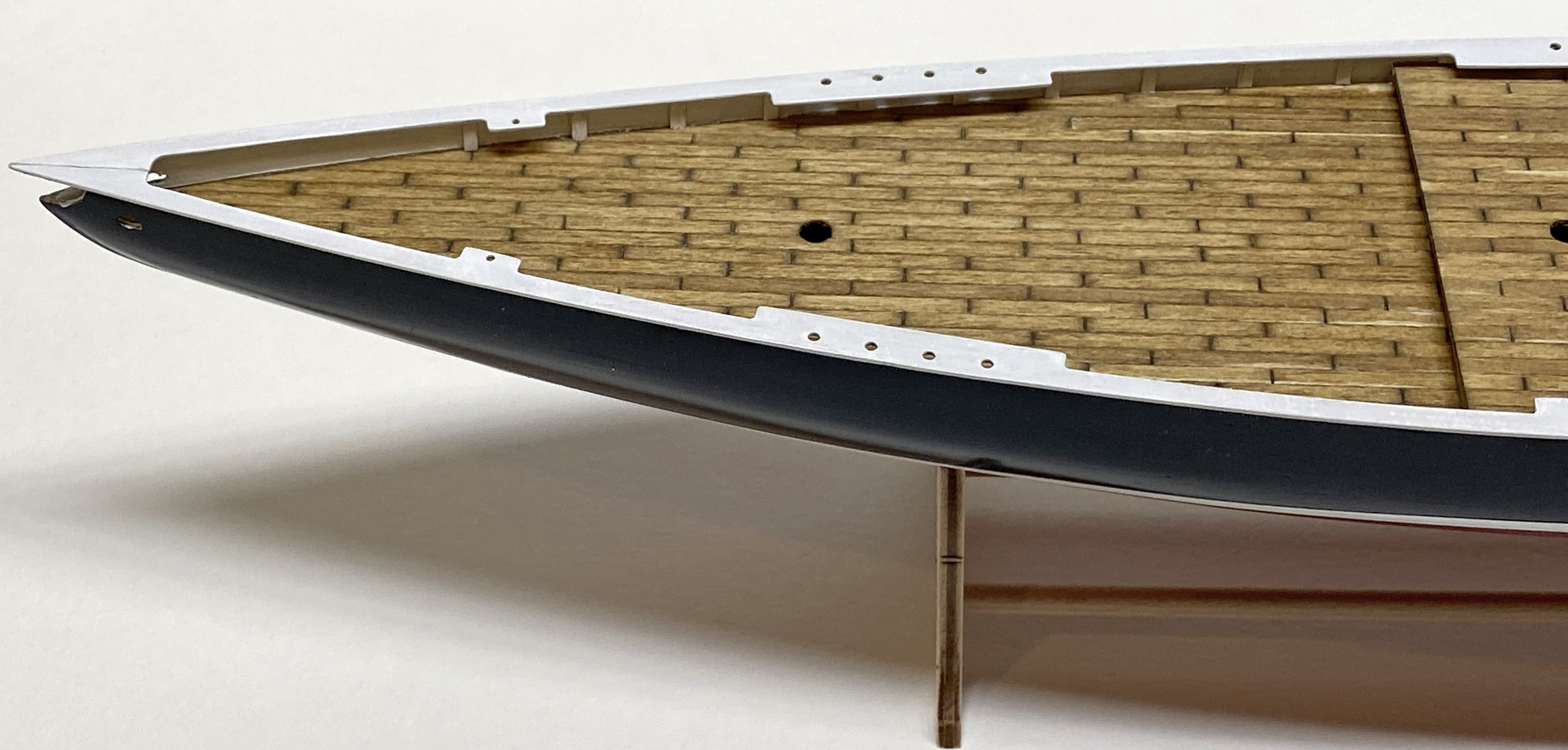
Hull Painted, Railing Installed - 23 days, 55 hours
The hull was painted with three coats each of Rustoleum Colonial Red, Krylon gloss white, and Krylon gloss black from rattle cans. The rails and interior were brush painted with gloss white acrylic. I am leaving for Europe in a few days and rushed to get this all done, but probably should have taken my time. I can see a few seams between boards and a few fingerprints on the black areas. Not bad but I could do better.

- Knocklouder, David Lester, ccoyle and 3 others
-
6
-
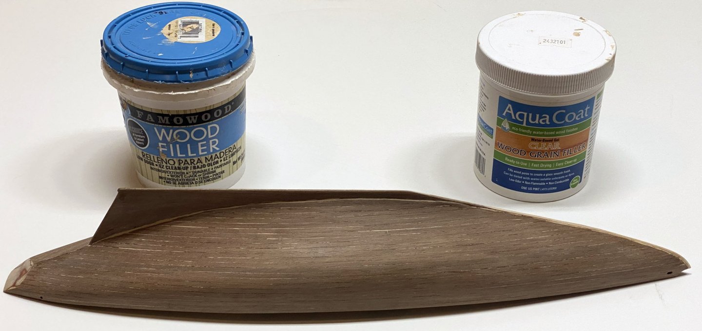
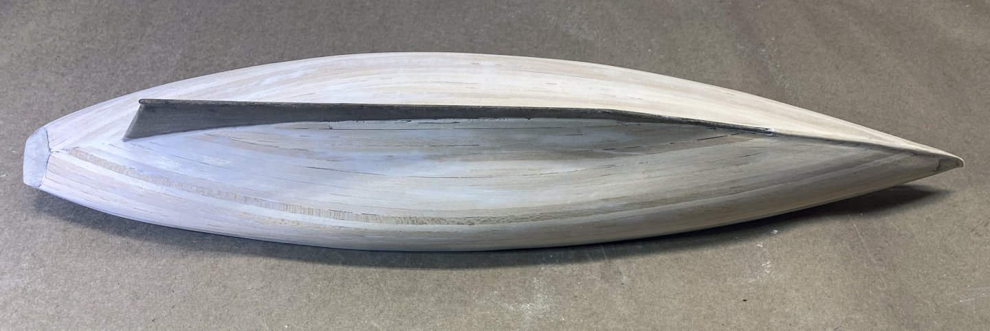
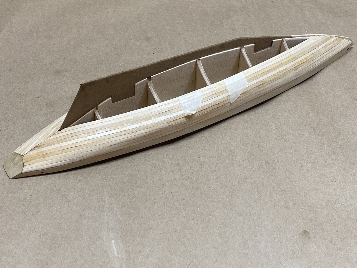
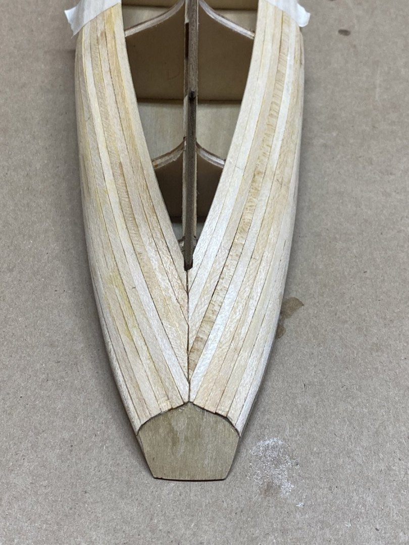
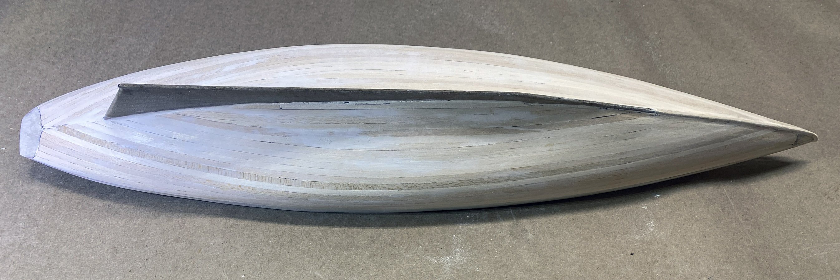
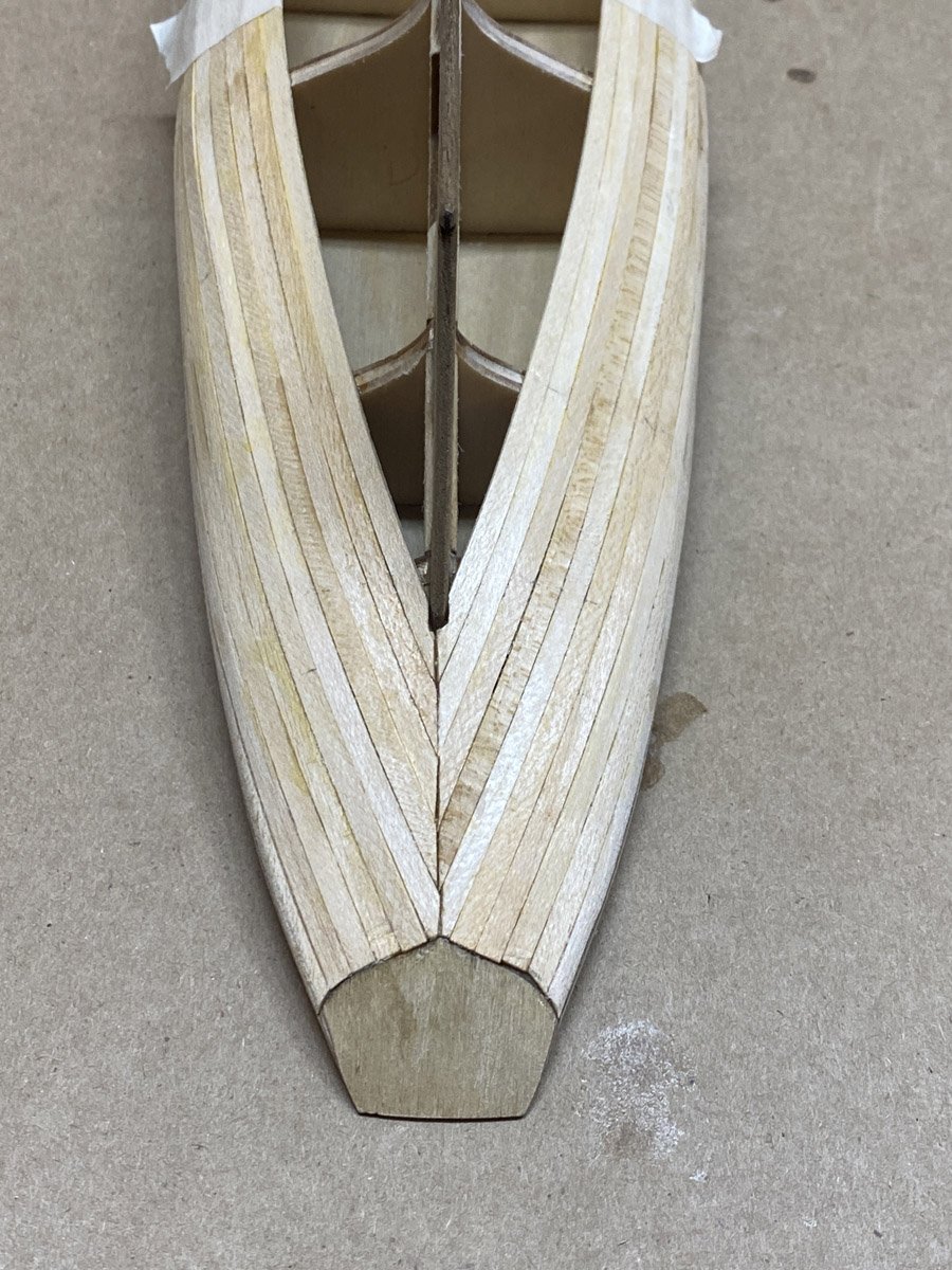
Second Planking Complete
I started at the top rail and worked towards the keel. The thin second layer of 0.5 mm walnut planks were amazingly flexible. I just glued them directly to the first layer with CA. No tapering necessary. After lots of sanding, crack filling with Famowood, more sanding, two coats of Aqua Coat, and more sanding, I think I am ready to paint the hull. At least I'll see how it looks after a coat of primer.
- ccoyle, gsdpic, Knocklouder and 2 others
-
5
-
First Planking Complete - 14 days, 31 hours
The second layer of planking is walnut, 3mm wide x 0.55 mm thick - not much material to sand down when I screw up. And why walnut if it's going to get painted anyway?
- GGibson, ccoyle, Knocklouder and 3 others
-
6
-
There are so many Bluenose build logs on MSW that I debated whether to add another. I am already glad that I did, since I've learned that the Maple Leaf flags that come with the kit are incorrect. However, I looked at the web sites for all the other Bluenose kits and guess what?
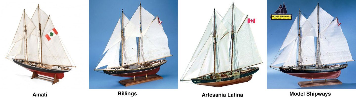
They all have Maple Leaf flags! What gives?
- Canute and king derelict
-
2
-
2 minutes ago, Kenchington said:
Here in Nova Scotia, I'm likely to get burned in effigy (if not in person!) for admitting it, but Bluenose did not win every race she was entered in. She did not even win every series of races, though she did win every International Trophy series, from 1921 on.
Besides, Puritan would have left Bluenose astern in anything but a hard blow, if Ben Pine hadn't run the big halibutter onto the Sable Island bar before she could race. No shame in that: The halibut fishery landed their huge flatfish fresh (on ice) and the schooners had to get their catches home to Gloucester before they deteriorated. The Lunenburg salt-banking fleet had to lie on Grand Bank, slowly filling their holds with split and salted cod. The two fisheries needed different schooners and, when racing-fishermen were developed from the two types, the one led to a light-weather flier, the other to a powerful vessel better able to use winds that were uncommon on the summer-time racing courses.
Trevor
And a P.S.: Please don't use either of those crude parodies of the modern Canadian flag! Bluenose never wore the Maple Leaf, which was only adopted many years after she was lost!
Trevor,
Thank you so much for the history corrections! I'm just repeating the text from the Italian instructions. Regardless of her win/loss record, she sure is a beautiful ship. Thank you also for the tip on the flags. I will certainly not use the ones supplied with the kit, and if you can suggest any alternatives I see what I can do.
- Knocklouder and Canute
-
2
-
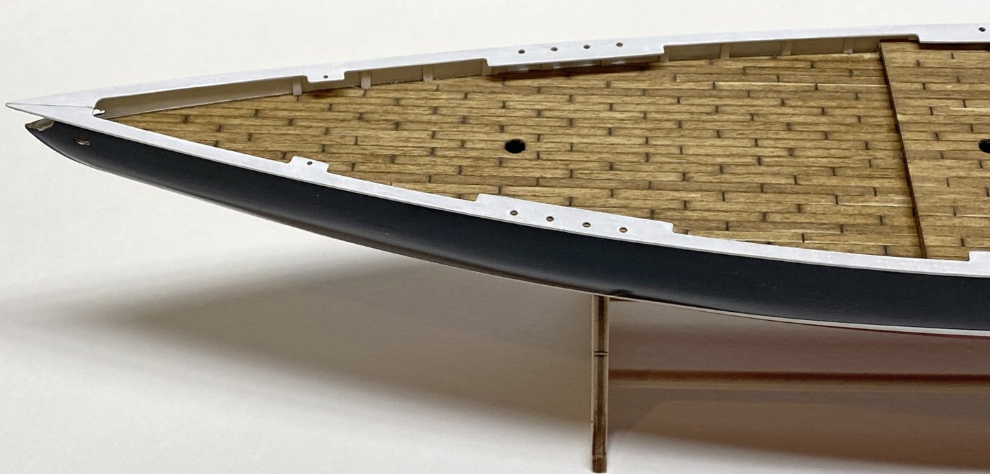
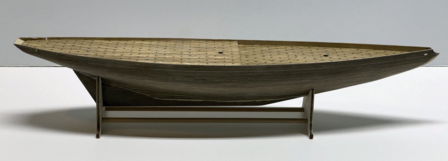
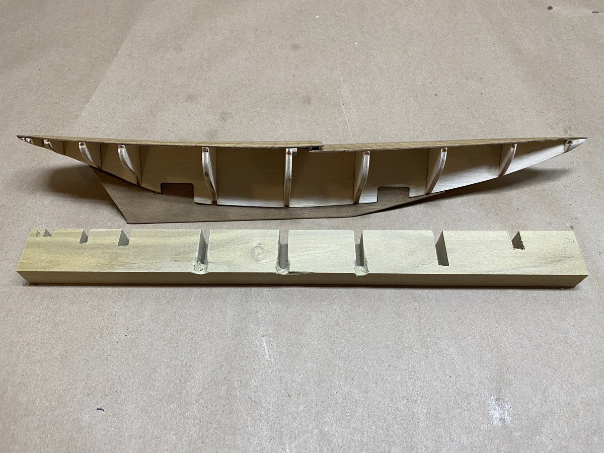
Starting on the Hull and Deck
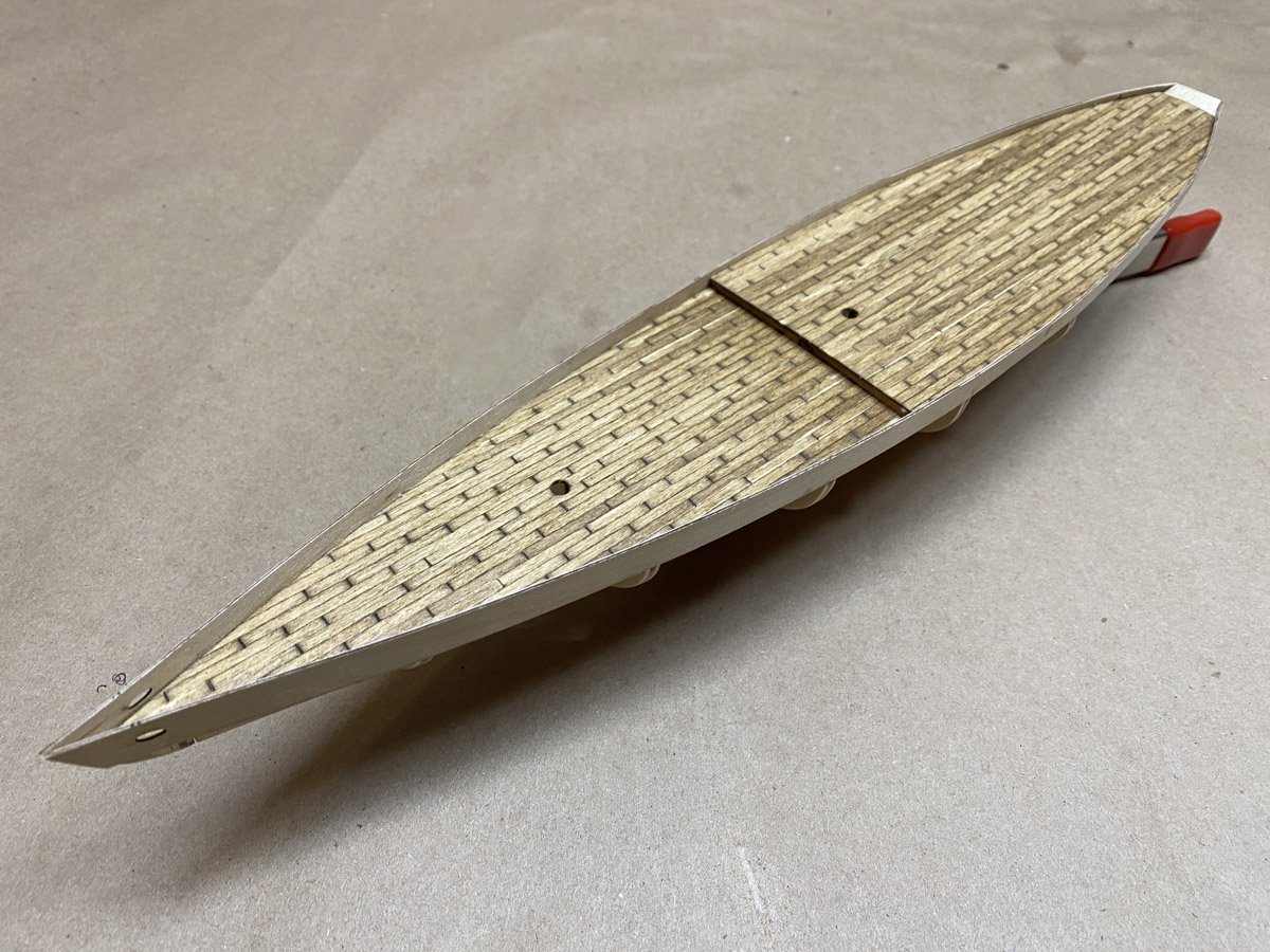
The frames popped out of the laser-cut ply and fit perfectly on the keel. I planked the two thin plywood sub decks by gluing down full-length strips and then notching them with a chisel to make individual boards. The technique is described here. I stained the decks with two coats of Minwax Golden Oak and finished them with Minwax Polycrylic satin from a rattle can.
When I test fit the decks on the keel they didn't line up in the center. Low and behold, the keel was warped about 4 mm off straight. Darn, I wish I had noticed that before I added all those frames. I ended up notching a piece of poplar to go around the frames. Clamped to the keel from below it held it straight while I glued the decks in place. The decks held the keel straight afterwards.
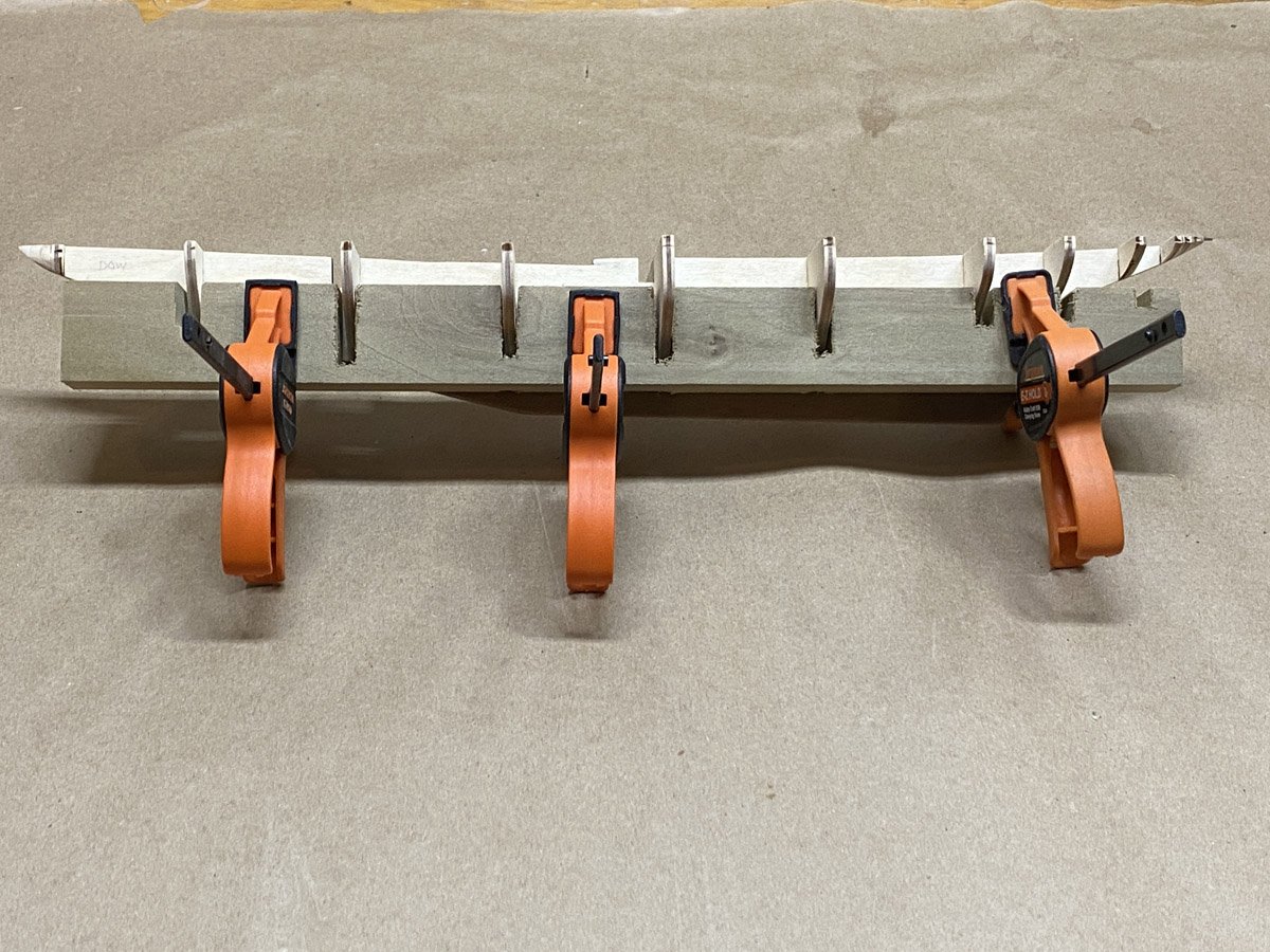
I've started the planking using the technique described in the book Ship Modeling Simplified: Tips and Techniques for Model Construction from Kits by Frank Mastini. Basically you glue the planks to the frames with CA, and glue the planks to each other with PVA (carpenters' glue.) The CA hardens in a few seconds and holds the planks in place, no nails needed. I do about three frames at a time. Oh yeah, I have a hot plank bender now and am using that to roughly shape the planks before attaching them.
The kit comes with a simple stand, but I usually prefer to mount my models on a permanent base - much easier to handle during construction and afterwards. But the sub keel on this model is just 2.25 mm thick, too thin for screws. I don't know what I'll do - maybe turn some wood pedestals and glue in place later?
- Canute, king derelict, hof00 and 2 others
-
5
-
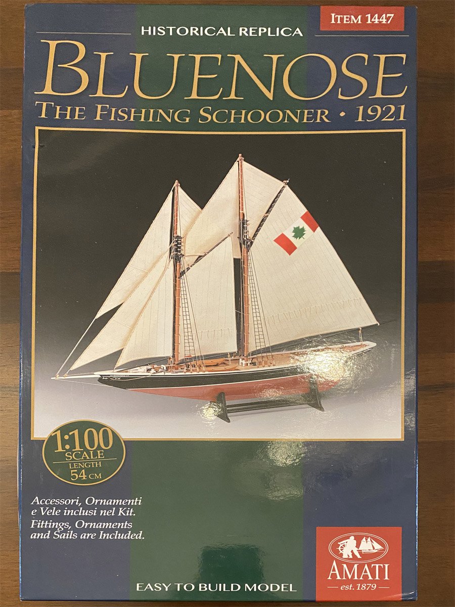
What's in the Box
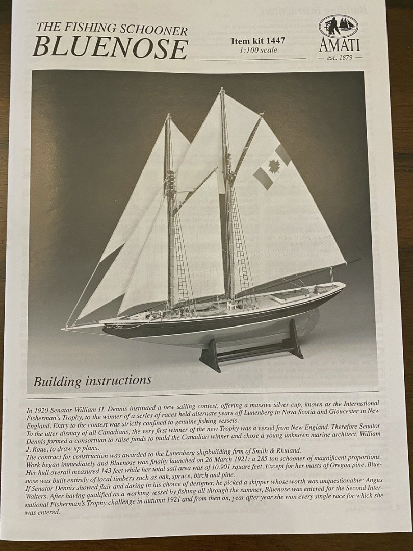
Seems like not much for €106.99, but that's what kits cost anymore.

I love the "EASY TO BUILD MODEL" text on the box. Easier than many of the models I've built lately, but with a planked hull and full set of sails this will be anything but easy.
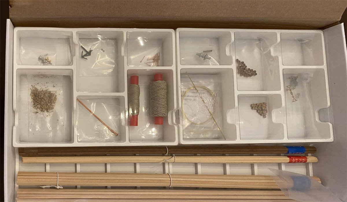
Planks, dowels, thread, blocks, and a few miscellaneous parts.

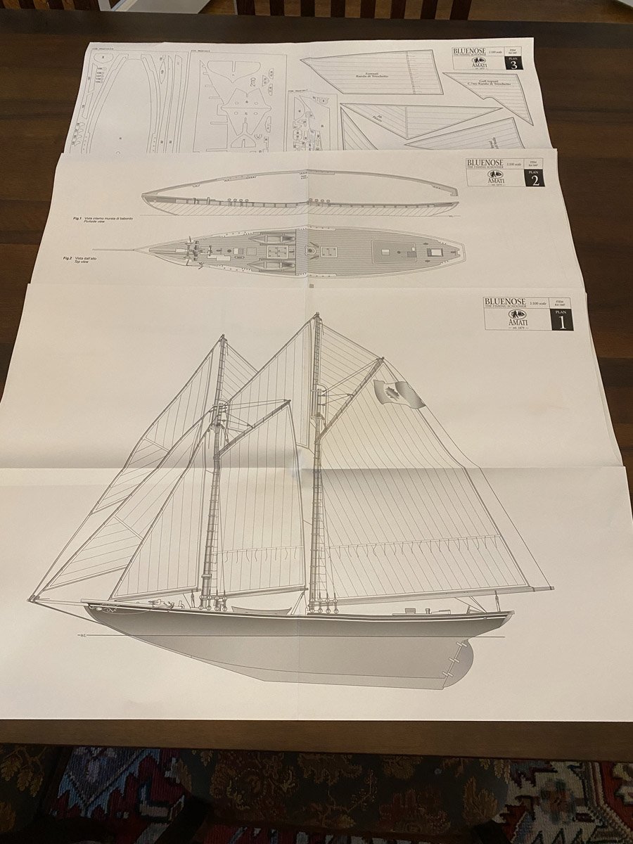
Three pages of full-sized plans.
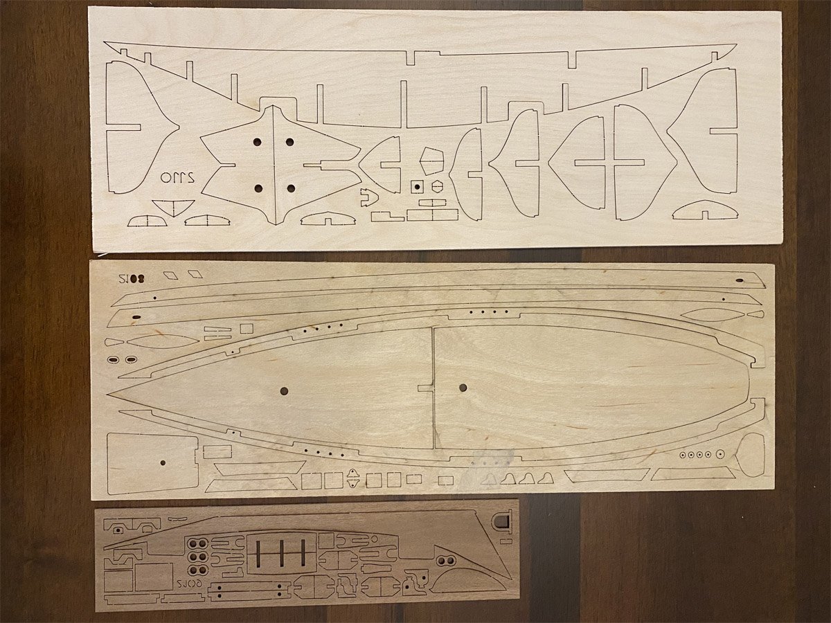
Three sheets of laser-cut parts.
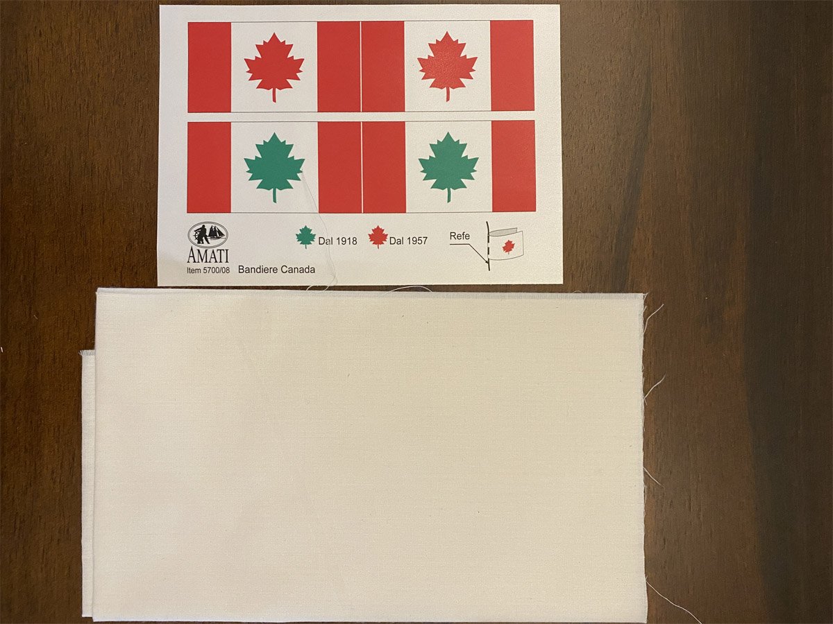
Two flags on adhesive-backed cloth, and cloth for sails.
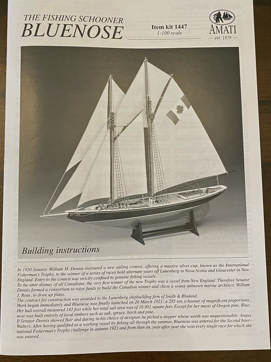
and a booklet with one page each of instructions in English and Italian, and about 20 pages of drawings.


Bluenose by rvchima - Amati - 1:100
in - Kit build logs for subjects built from 1901 - Present Day
Posted
Bluenose II, Saga of the Great Fishing Schooner by L. B. Jensen
I finally bought a good reference book for the Bluenose, at least Bluenose 2.0. The cover is deceptive - the book measures 11" x 14". It is entirely hand drawn and lettered, and is filled with excellent detailed drawings of the ship. Now I can see what details I've already got wrong.
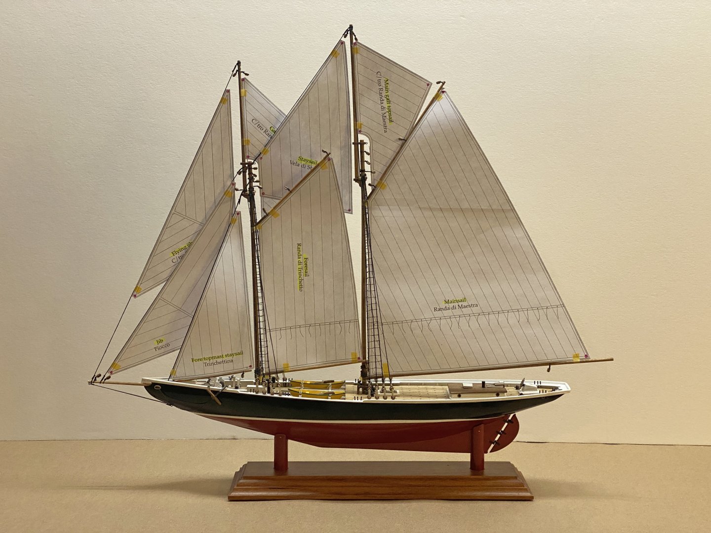
So what's wrong with this picture?
If you guessed that the seams between fabric pieces on the jib and jib topsails are much wider than those on the mainsail you are correct. I copied all the seam patterns directly from the plans and never noticed the discrepancy until now. The seams on the mainsail are spaced 1 cm apart, or 39" at full scale - very reasonable for 1920s fabric. The seams on the jib and jib topsails are 13 mm apart, or 51" at full scale - way too big. Would anyone ever notice? Probably not but I'll have to redraw them anyway. Note: you cannot erase pencil marks on silkspan.