HOLIDAY DONATION DRIVE - SUPPORT MSW - DO YOUR PART TO KEEP THIS GREAT FORUM GOING! (Only 24 donations so far out of 49,000 members - C'mon guys!)
×


rvchima
-
Posts
697 -
Joined
-
Last visited
Content Type
Profiles
Forums
Gallery
Events
Everything posted by rvchima
-
 Wow, I wish that was available a couple of years ago!
 -
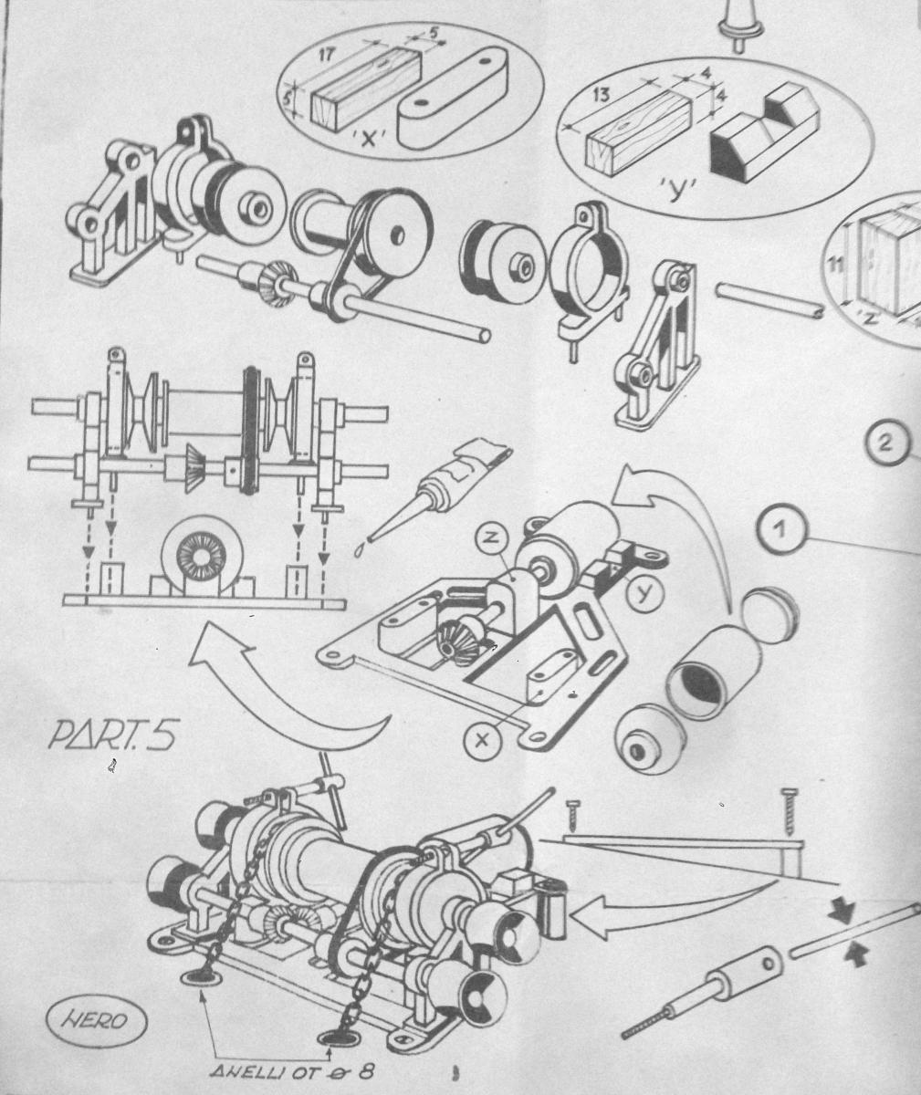
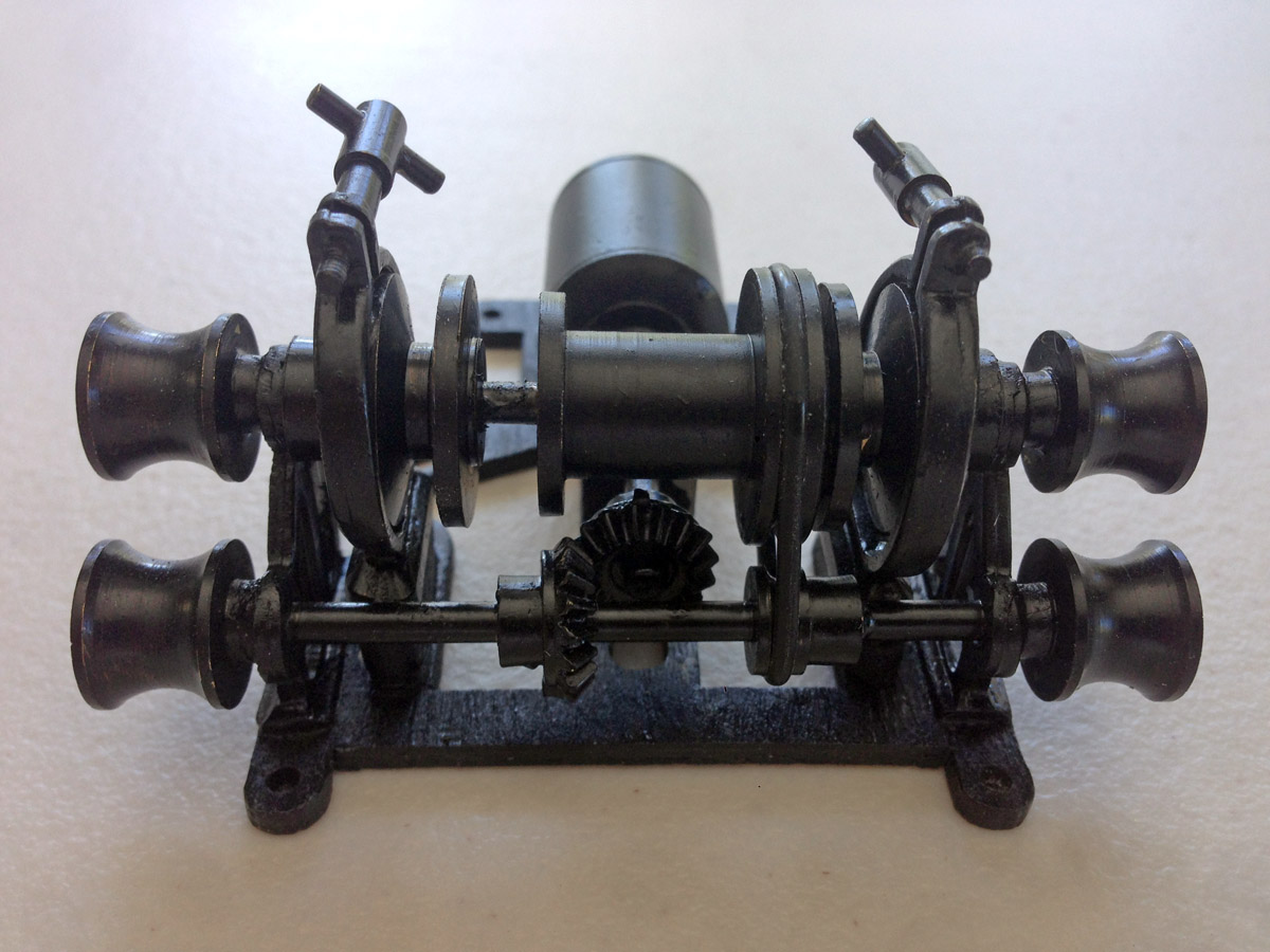
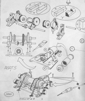
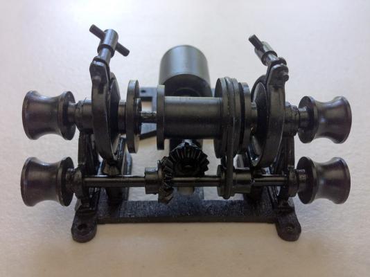
Winch Plans for Lou A couple of weeks ago Lou asked for more details about the winch. Sorry Lou, I completely forgot. The plans for the winch are attached below. The frame is laser cut ply, and the mounting blocks are basswood. All of the other parts are turned brass. The motor is a dummy brass shell with endcaps, but the gears and brakes could all be made to operate if you wanted to go to the trouble. I hope this helps.
-
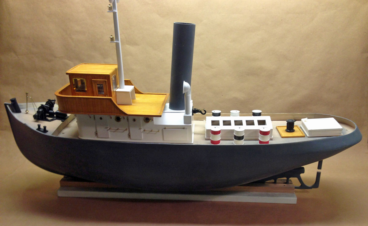
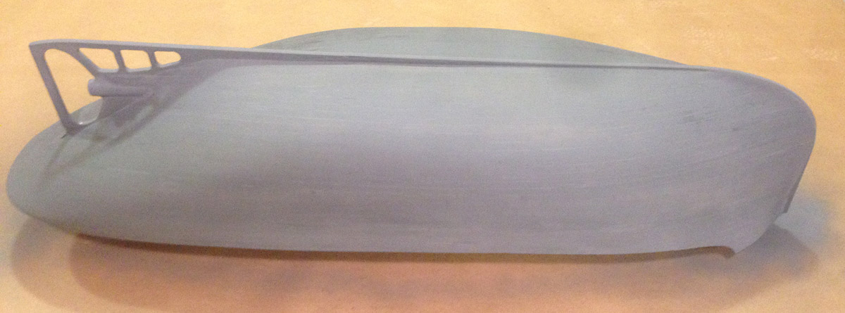
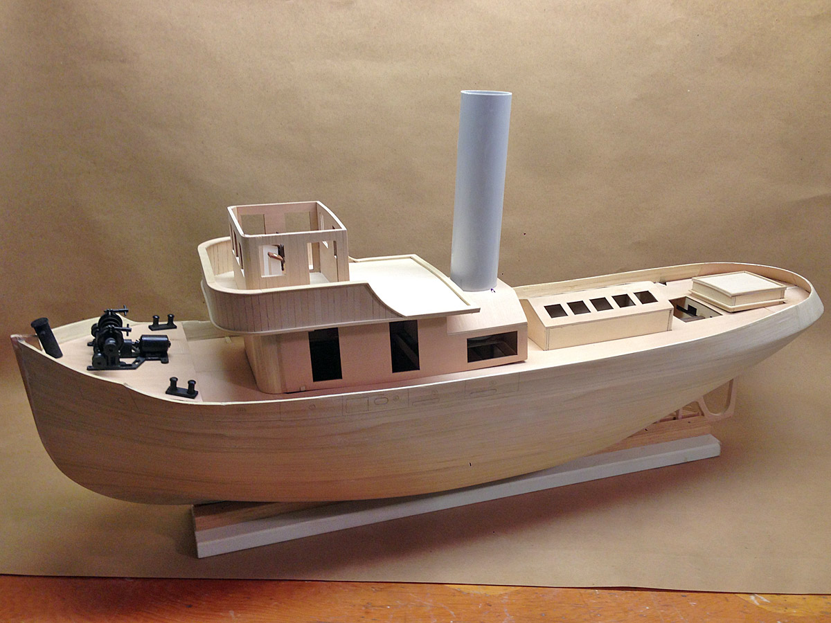
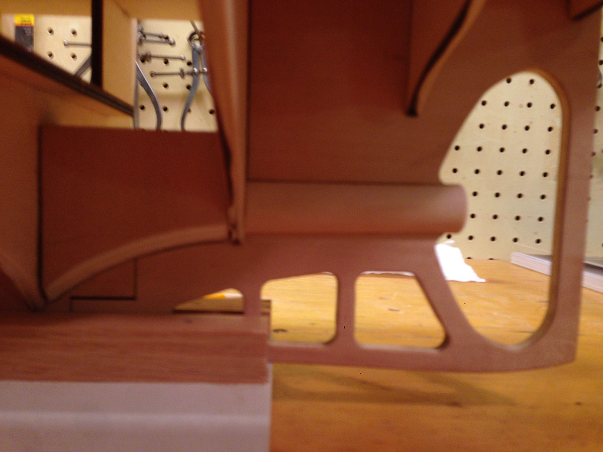
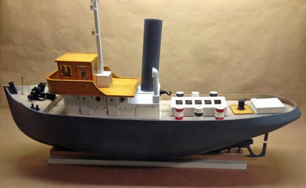
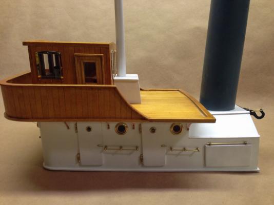
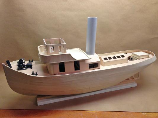
Overall View Here's where it stands today. The hull and stack are both primed grey and ready to paint. The engine house and aft structure are primed white and will be painted the same color as the stack. There is a notch cut in the rudder support for installing the prop shaft. I will have to glue the cut out piece back in place and repaint after the prop is installed. Too bad the shaft can't be installed from inside the hull.
-
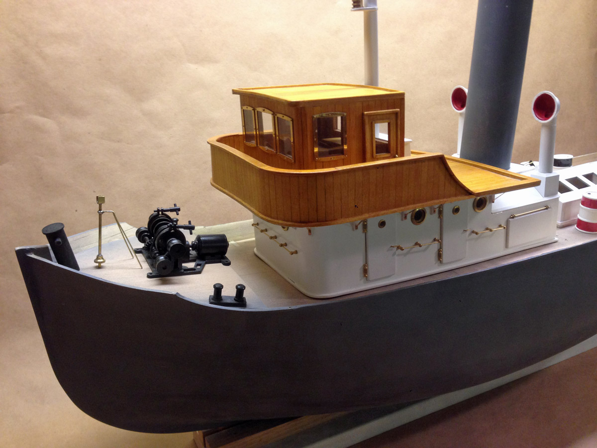
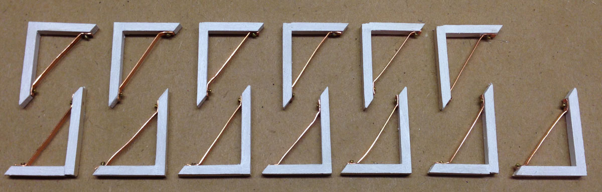
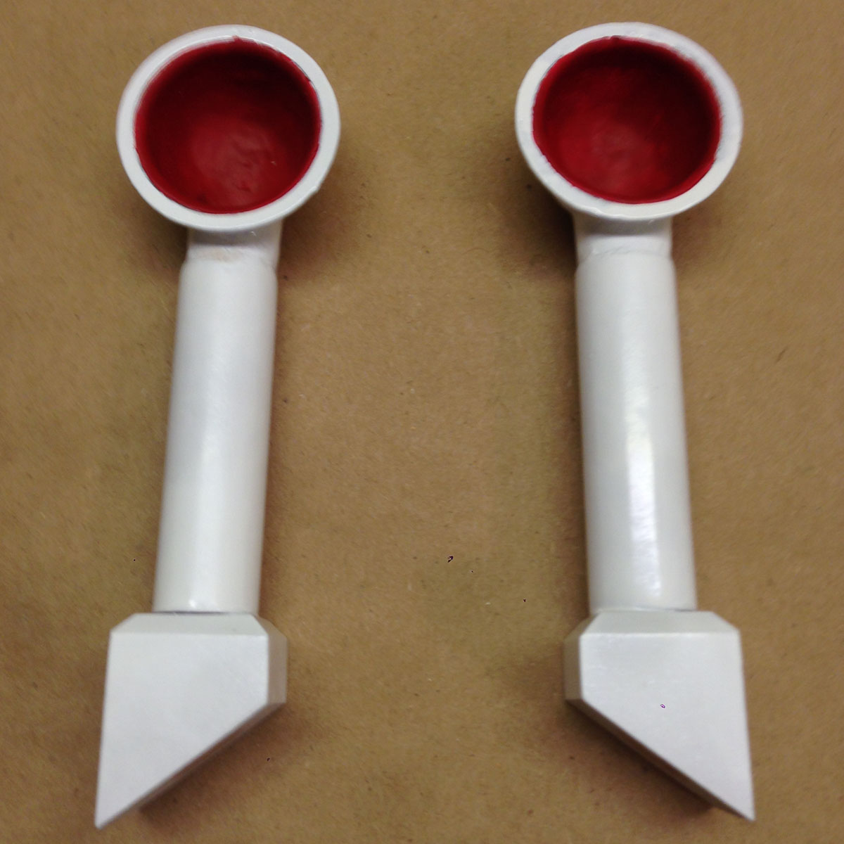
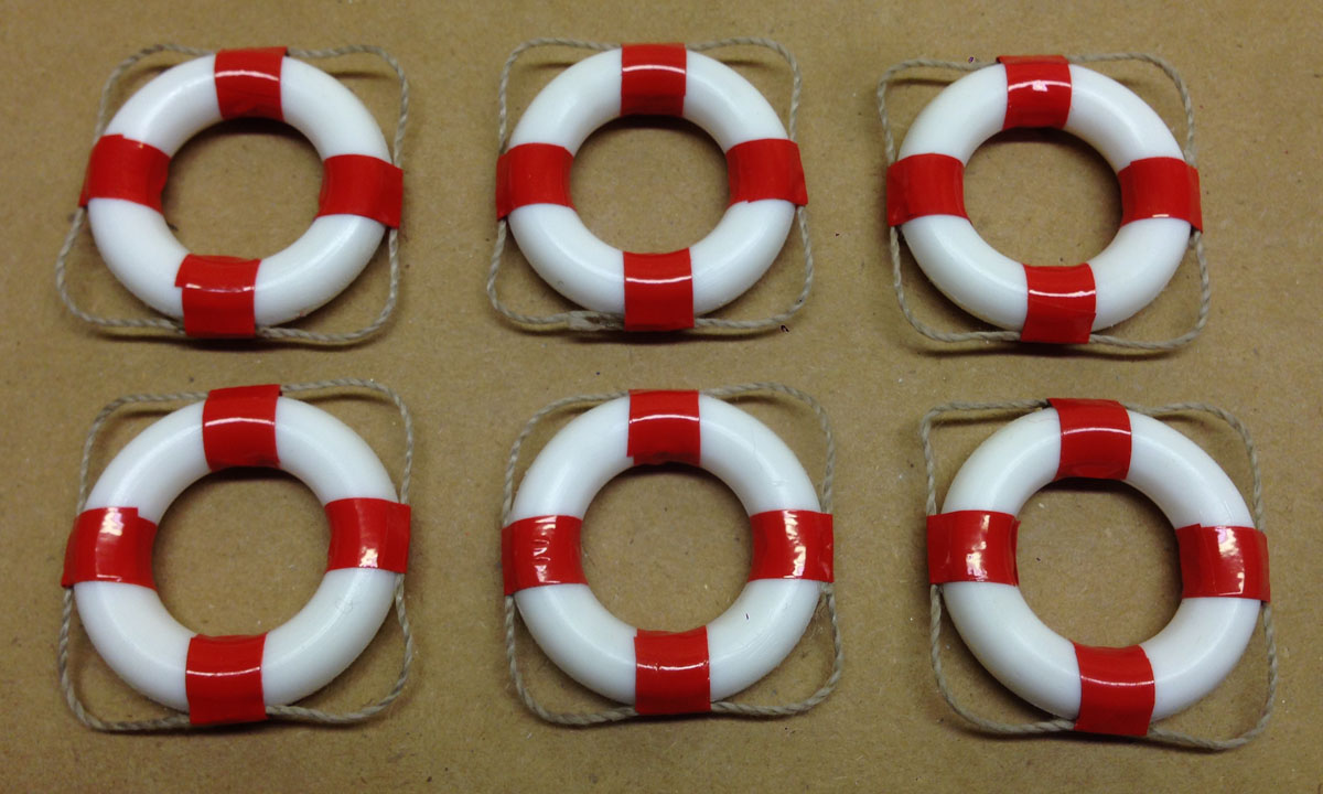
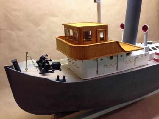
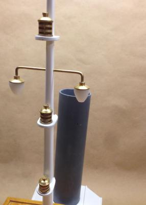
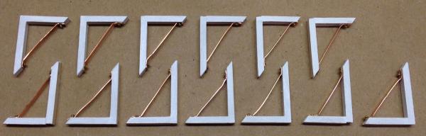
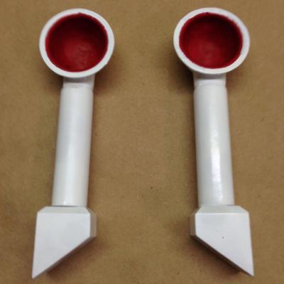
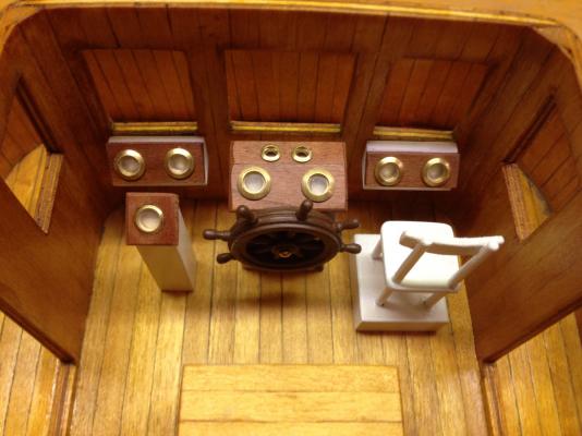
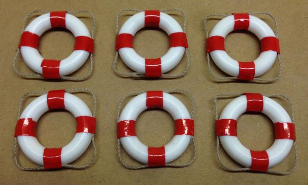
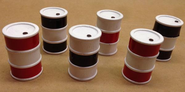
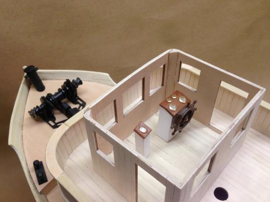
Cabin While waiting for my paint to arrive I jumped ahead in the plans and completed the cabin. The instrument panels are made of lacquered cherry, and the planking is finished with 3 coats of orange shellac. Panart supplies a lot of beautiful brass pieces for portholes, hinges, and railings that really dress the model up. They also explain the high cost of the model. So far I've run short of some wood strips, but every brass piece has been neatly bagged and in the box. Here's a view of the bow with the cabin in place. Lots of Little Parts. 208 hours, 160 days. Lately I've been building lots of little, difficult parts. The mast was hand planed to shape from a 12 mm dowel. The brass lights were all supplied. These 13 braces support the deck where the cabin overhangs the lower quarters. The funnels are made of a brass casting on top with wooden supports below. Six life preservers are made from plastic rings and red striping tape. They will eventually hang on the cabin. Six turned wooden barrels were supplied. I painted them, then wrapped them with model airplane trim tape. The fill caps are painted nail heads.
-
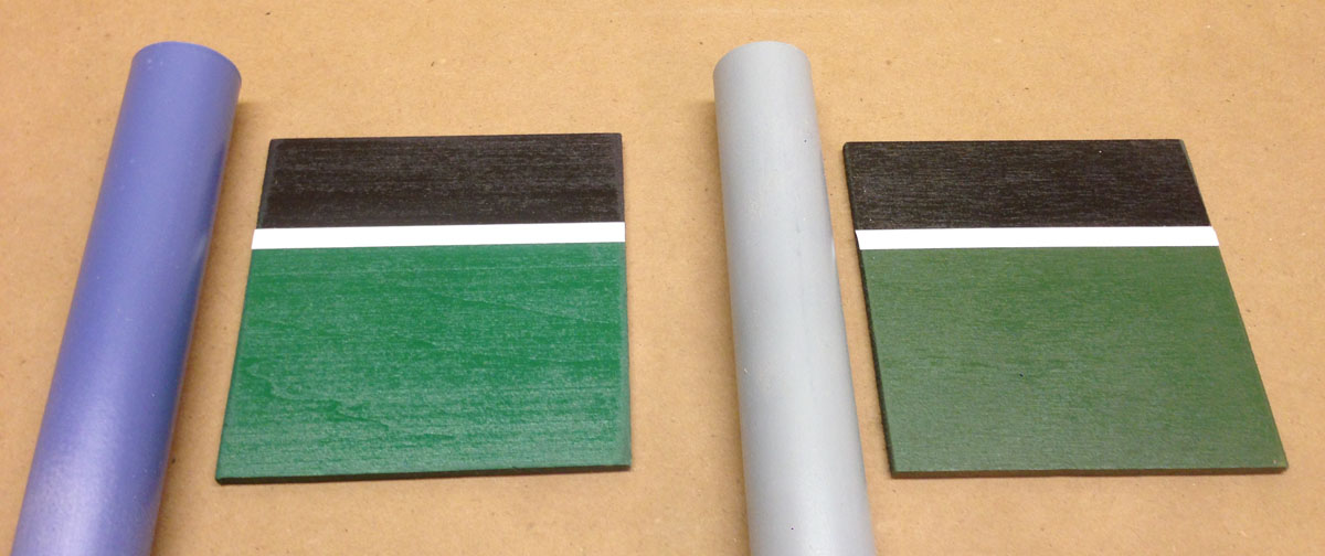
Color Scheme Blues, and Greens The model on the box is painted an interesting blue-green color that has been hard to match. I went so far as to analyze a digital photo of the model, extract the red/green/blue components of the hull color, and compare to color charts from Krylon, Testors, and Rustoleum. The closest match was Krylon's appropriately named "Surf" color, which I was unable to find locally. I ordered a can from a supplier on amazon.com 16 days ago and haven't received it yet. Handy Tip: Don't order from Bic Warehouse. In the meantime I bought a couple other Krylon paints and made some color samples. On the left is "Emerald Green," with "Periwinkle" for the stack. On the right is "John Deere Green," with "Pewter Gray" for the stack. I really like the combination on the left, but hate to start painting until I see what "Surf" looks like. What do you think?

-
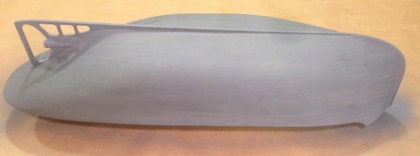
First Coat of Primer The next step in construction is to plank the deck and add a third layer of planking to the inside of the rails. But I plan to paint the outside of the hull first to keep paint off the deck. Here's the first coat of primer. Tomorrow I'll take a good look and fill all the cracks I missed before. Wanted: Ideas for a Stand I won't be able to use my keel stand anymore after I finish painting the hull. I would like to build a stand that looks like a tug up on wood blocks in dry dock. Here's a photo of a different tug model on a stand like I have in mind, but I do want to be realistic. I have searched online for a cool photo of a real tug in dry dock, but I haven't found anything to my liking. If you have have any ideas for an appropriate stand, please post photos or links, or message me directly. Many thanks.
-
Full Profile View I haven't posted a full profile in a while, so here's what it looks like now. The cabin and engine house are just laying in place. I've built a few fixtures for the deck and cabin, but there is a lot more to be made.
-
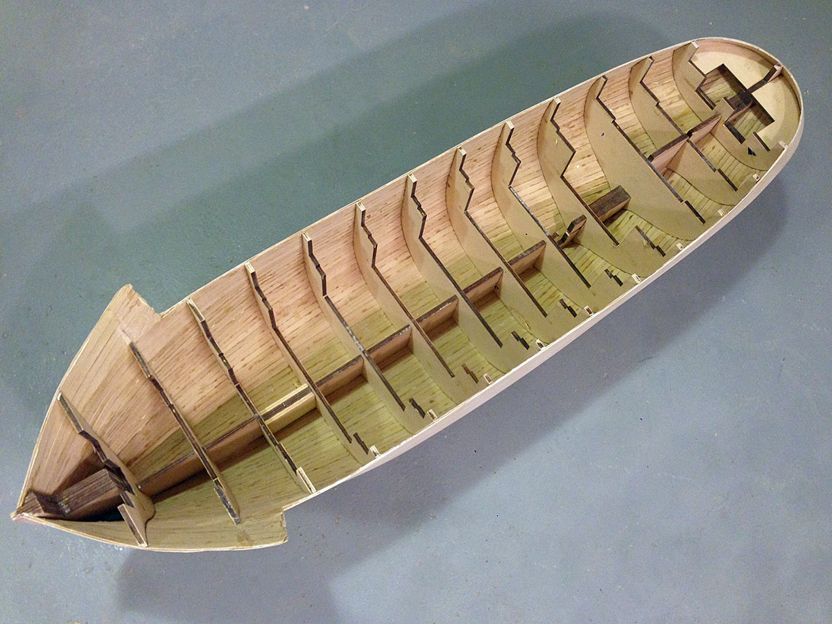
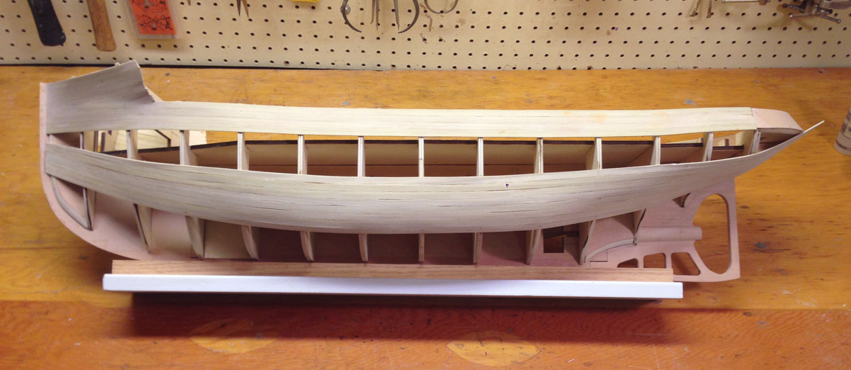
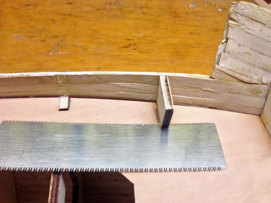
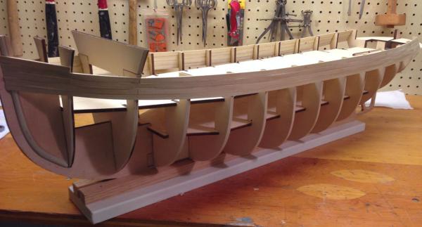
Temporary Decks Removed Two temporary decks made of heavy plywood were used to keep all the bulkheads in alignment during planking. They were held in place with small nails and were easily removed. This is the fist time I've seen the inside of the ship since January. Sub Deck Installed, Bulkheads Trimmed And now the inside is hidden again. A sub deck made of very thin laser-cut plywood was installed near the top of the bulkheads, and then the bulkheads were all trimmed to deck level. I thought that would be difficult, but not with this flexible Japanese cut-off saw. I sliced the bottoms of the bulkheads flush with the sub deck, then gently rocked each piece back and forth with pliers to break the glue joint. I know the insides of the side rails look terrible right now, but after I sand them and add a third layer of finish planking on the inside they'll be fine.

-
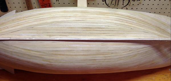
Second Layer of Planking Completed - 120 hours, 122 days I FINALLY finished planking the hull and will soon be moving on to more interesting things. For the first layer I tapered most of the planks, and it took 58 hours. For the second layer I left most the planks straight. It only took 20 hours and it looks much better. In the photo you can see a crescent-shaped area left at the bottom where I had to trim the planks to fit. Helpful Hint - When basswood planks are wet you can cut them with scissors. I wish I had realized that that 4 months ago.
-
Second Layer of Planking One reason that I chose this model that I wanted to build a double-planked hull. Now I wonder "What was I thinking?" On the first layer I tapered all the planks so that the same number of planks would cover all the bulkheads. That worked out well, but it was a lot of work. On the second layer I started at the top and worked down, with full width planks almost everywhere. I did use a couple of cheaters here and there to keep everything straight. I am now about half way down the hull, and this layer looks much nicer than the first. Eventually the planks will stop way short of the bow, but I think they will be OK. We'll see.
-
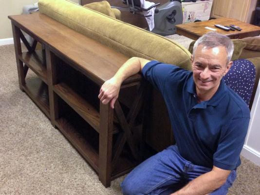
A Major Digression Sorry for the long delay between posts, but I stopped working on the tugboat model long enough to build a sofa table for my son and his wife. The table was based loosely on a design that I found online, but I modified it so that it could be completely disassembled to fit in the back of a Toyota Prius. The table is now safely in North Carolina and I am back to work on the tug.
-
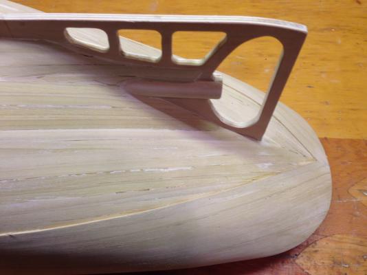
Bridge House - 86 hours over 57 days The bridge house is framed up in laser cut plywood, and then planked with limewood (basswood) strips. The instructions said to build the whole structure before doing the planking. As soon as I started planking I realized that it would have been MUCH easier to plank the deck before adding the curved rail, and to plank the cabin before gluing it in place. From now on I'll try to read ahead a little. My wife and I are in Florida for a while. She is an author and only needs her computer to work. I tried to bring enough of the Anteo kit, tools, and supplies to keep me busy. But I forgot my drills, and I brought all the wrong paints. So I'm jumping around in the instructions and building what I can. I'll try to sort it all out when I get home.
-
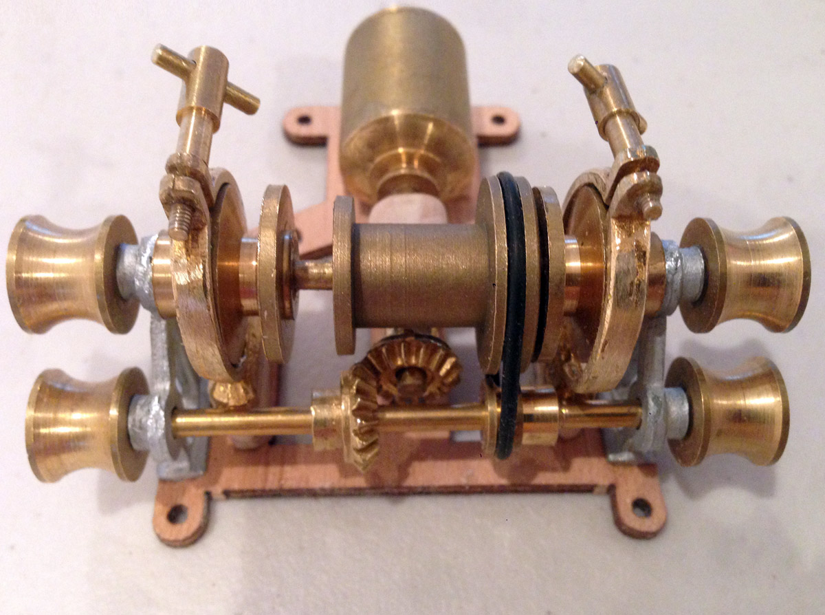
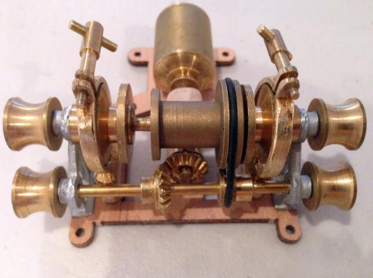
Windlass The parts for the windlass were mostly turned brass and were incredibly detailed. With a little work and a real motor you could probably make it operate. The brass was so pretty it was a shame to paint it.
-
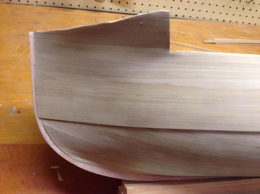
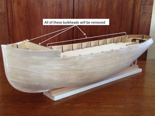
First Layer of Planking Completed. 58 hours, 39 days I completed the first layer of planking the other day. This boat is BIG! I don't know where I'm going to put it when it's done. After a lot of sanding, I filled the wood with a coat of Behlen water-based grain filler (available from Woodcraft.com). This stuff has the consistency of yoghurt, it dries quickly, and it sands off easily. I was amazed at how many cracks and depressions it found! You can see all the white areas in the photo. The stern is still pretty rough, especially around the prop shaft. Looking ahead in the plans I realized that all of the interior bulkheads will be removed down to the deck level, leaving a thin layer of planking to the side rails. A single layer of planking would definitely not be strong enough, so I'll have to bite the bullet and add a second layer. But I think I'll set that aside for a while and work on some of the superstructure.

-
I've never done a double planked hull before, and I am pretty happy with the single planked hull so far. A little putty in the cracks might be enough. Everything gets painted eventually anyway. We'll see.
-
More Planking We're having a major blizzard today so it's a great day to stay indoors and attach planks. I added a plank down the centerline of the bulkheads. Then I measured the remaining height above the centerline along each bulkhead. The longest segment is about 13 planks high. I divided each segment by 13 to get the height of the plank at that bulkhead. Then I tapered a bunch of planks and let them soak. I am now using white PVA glue along the plank edges and dots of CA at the bulkheads. If I do two bulkheads the CA makes instant pins to hold the plank while the white glue dries. There is much less CA oozing out and my fingers are clean. So far so good.

-
First Rows of Planking The planking is 7 mm limewood. It's very flexible when it's wet. I glued the first few rows entirely with medium viscosity CA. Maybe that wasn't such a good idea. Now where's my acetone?
-
Stand and Prop Shaft Housing Here I made a temporary stand that is a tight fit on the keel. The prop shaft housing was made of two rectangular blocks. I taped them to a 3/16" square stick with double sided tape, chucked them in the drill press, and sanded them at high RPM. THen I pulled the tape apart and glued the half-cylinders to the keel over a slot for the prop shaft.

-
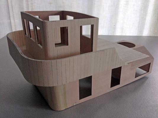
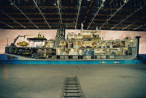
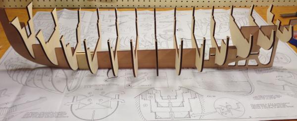
Bulkheads and Subdecks Installed Two subdecks have been temporarily nailed into place to keep the bulkheads aligned while the planking is applied. This will also eliminate any residual warping in the bulkheads. At this point the model totally reminds me of Steze Zissou's ship, the Belafonte, from Wes Anderson's "The Life Aquatic."
-
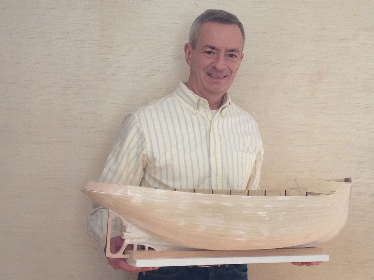
The completed model will be 35 inches (890 mm) long. I will build it for display only, not RC.
-
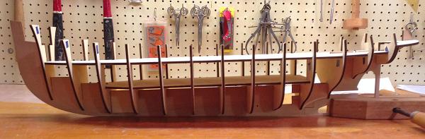
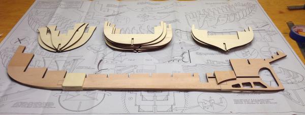
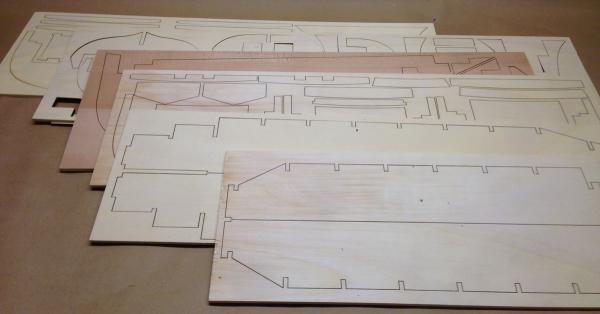
First Construction Photos The laser-cut parts popped out of the sheet easily and the 3-piece keel when right together. Here's the keel with all the bulkheads in position. But here's also where I found a problem with the kit. One of the 6 pieces of 1/4 inch ply has a warp built in, and 5 bulkheads are seriously warped. I soaked them in hot water and clamped them to flat boards. I hope they straighten out before I glue them to the keel. Once the planking is attached they should be fine.
-
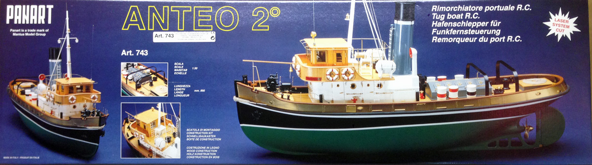
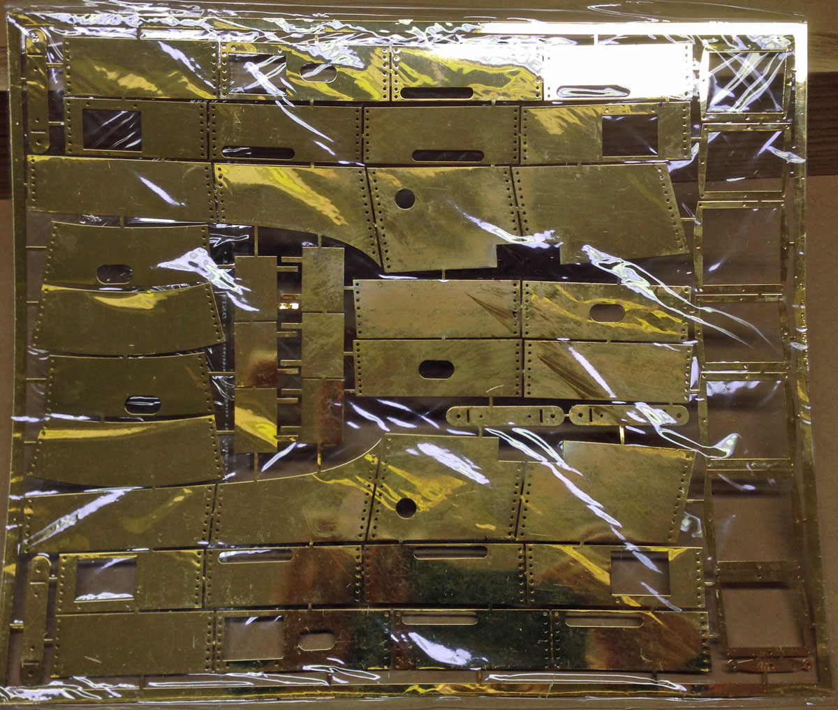
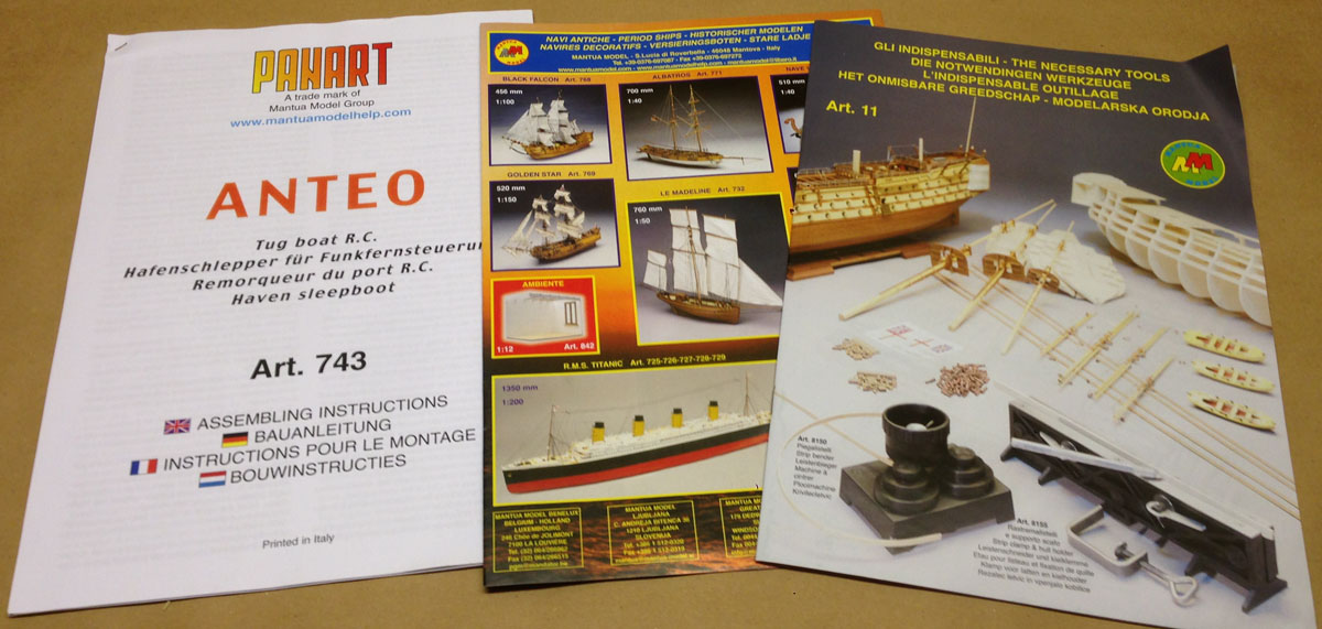
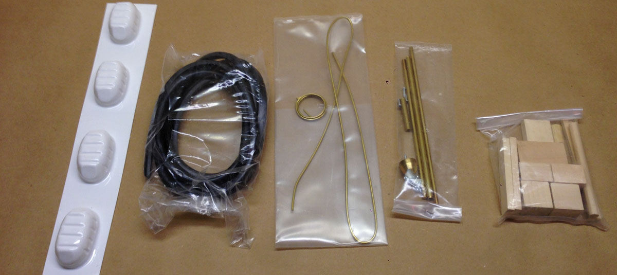
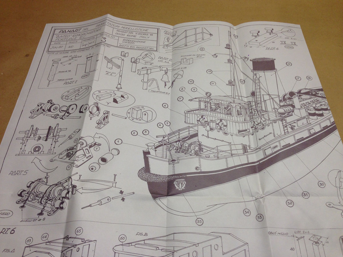
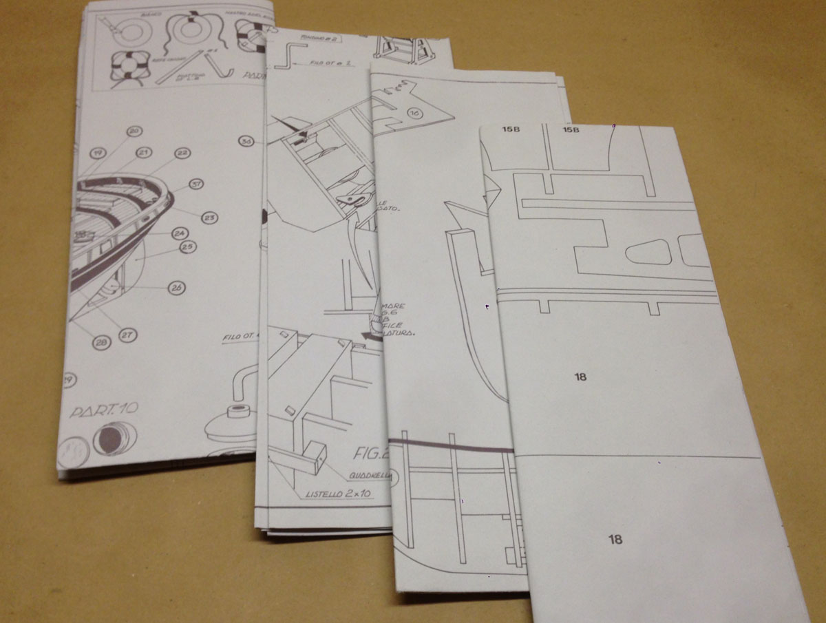
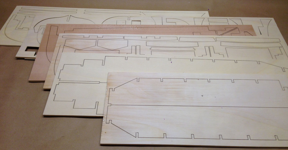
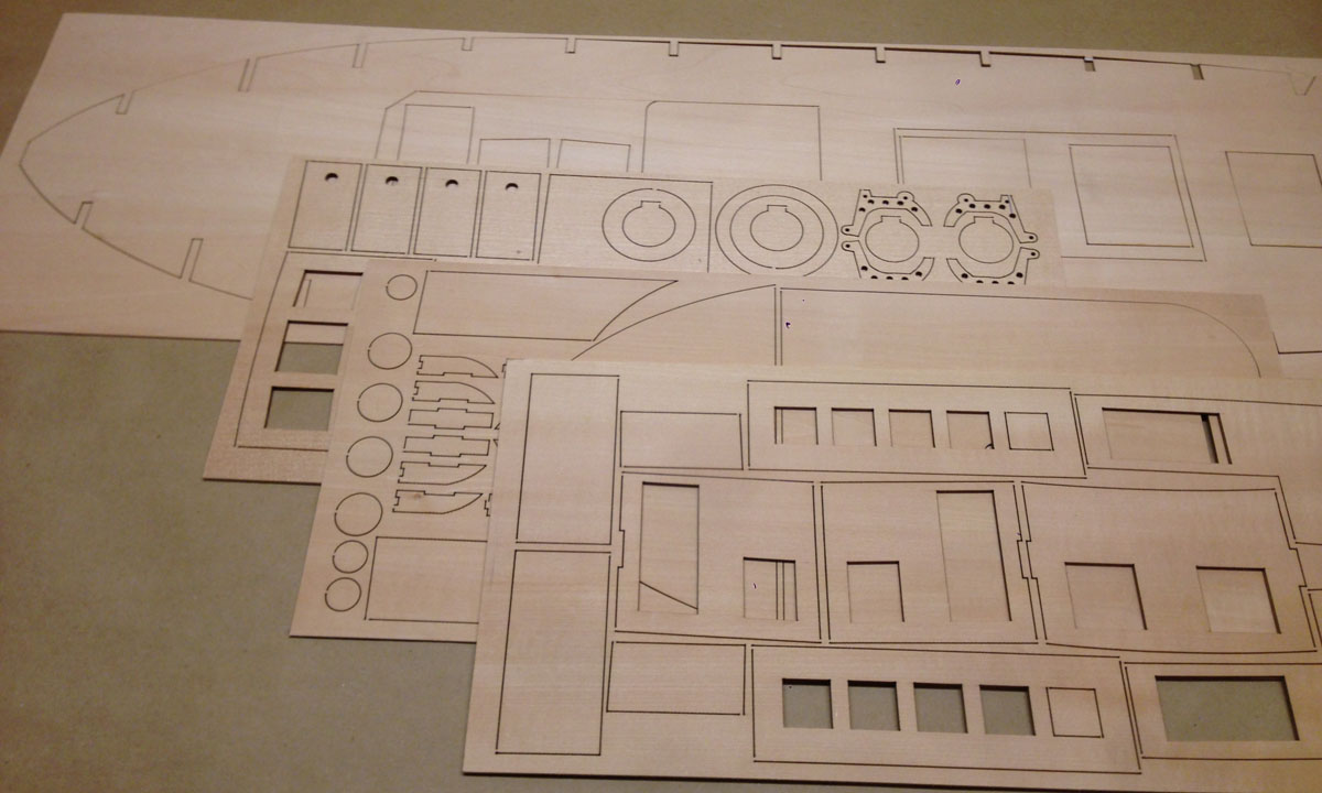
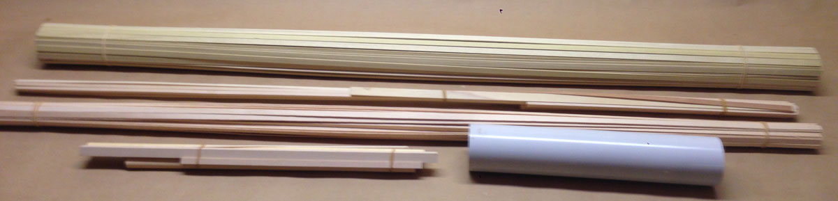
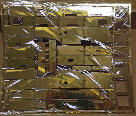
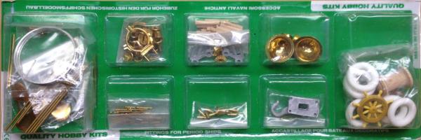
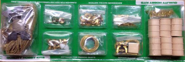
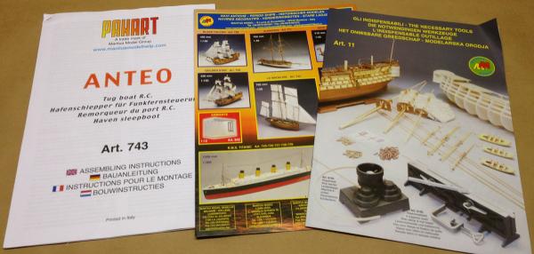
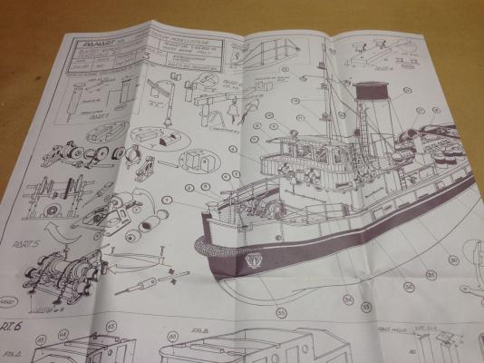
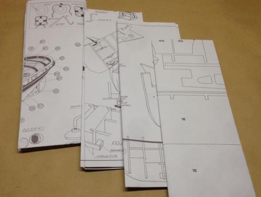
Another Very Different Model (for me, anyway) My wife gave me another ship model this Christmas. Of course I gave her strong hints what I wanted. What I wanted was a working vessel with clean lines, a planked hull, and no rigging. After a long search I found the Anteo harbour tug by Panart, which seems to be a part of Mantua models in Italy. Please let me know if I am wrong about this. I ordered the kit from Cornwall Model Boats in the UK. Even with shipping to the US their price was significantly cheaper than anyone else. I ordered the kit on a Sunday and had it in my hands the following Thursday. Amazing service. I gave the box to my wife and opened it on Christmas morning. What's In The Box. First of all, the box measures 37x11x4 inches and weighs a whopping 12.5 pounds! It is packed with quality parts. There are two packages of fittings including funnels, the wheel, tires, the prop, line, portholes, lights, and the anchor. Planking for a double-planked hull , heavy PVC stack. Vacuformed lifeboat shells, rubber bumper material, brass prop shaft. 6 sheets of 1/4" laser-cut ply. 4 sheets of thin veneer ply. A large sheet of photo-etched brass. Instructions in 4 languages plus 2 catalogues. The English instructions are short and pretty rough. 4 pages of plans, 2-sided, 27x39 inches.


-
Hi Augie, I look in ocasionally and am always inspired by your work. Happy Holidays! Rod
- 2,191 replies
-
- 1
-

-
- confederacy
- Model Shipways
- (and 1 more)
-
Peter, Cutting and assembling the polystyrene cowls was the hardest part of this model. I cut the plastic by making several passes with a sharp razor knife against a heavy steel ruler. I often clamped a scrap of wood over the edge of my workbench to set the plastic on while I cut it. For the front intake and exhaust manifolds I drilled holes at the ends first, then cut out the rest with a razor. I sanded all the edges straight using wood sanding blocks. The plastic picks up static electricity and the dust sticks all over your clothes. I glued the cowl halves together using CA glue made for plastic. The glue dries slowly on plastic so I used masking tape to hold it while it cured. The reinforcing strips on the inside of the cowl shown on the plans are important for strength. After the glue cured I sanded the joints flush, filled the cracks with putty for plastic models, and repeated the process several times. The rear cowl came out almost perfect but the joint is still visible on the forward cowl. As I worked on the forward cowl I kept breaking the joint in the center of the open end, where the top of the dashboard ends up. Eventually I glued a reinforcement on the inside. That solved the breakage problem, but I later discovered that it interfered with the dashboard and I had to cut it off. That was not easy after the cowl was all painted. Feel free to ask other questions. I will send my e-mail address by private message. Even if you don't post a build log maybe you can a photo of the model occasionally. Rod
-
Peter, Thank you for your kind comments. I am happy to see someone else building the Amati hydroplane kit, and I do hope you will post a build log. The hull was actually a lot of fun to build. I assembled almost the entire model using medium cyanoacrylate (CA) glue, so there was little need for pins or clamps - only fingers. The framing is trivial with the laser-cut parts. The plywood sheeting fit almost perfectly, but on the bottom I sanded through some ply layers. I ended up covering over the bottom sheeting with expensive self-adhesive mahogany veneer. The veneer looks better than any stain that I could have applied to the plywood, so it was a lucky mistake. I can send you a link to a US supplier of the veneer if you are interested. Before you start planking the hull make a sample by planking, nailing, and finishing a small scrap of wood to get a feel for the process. To plank the top I marked the center line, then laid out a line on each side touching the top cowling frames, and equally spaced from the center line fore and aft. I planked along those two lines first by cutting the strips a little long, soaking them in warm water for 5-10 minutes, then gluing them to the frames with CA. Glue three frames at a time. The CA dries very quickly when exposed to the damp planks, then you can bend the end up and glue the next 3 frames. Then add planks inwards and outwards from there. I ran slightly short of planks and had to buy a sheet of hobby mahogany the same thickness as the planks, and rip some strips on a band saw. You could do this with a razor knife if necessary. When everything was done I trimmed the ends with a razor saw. Oh, and don't forget to mark the frame locations on the tops of planks for nail lines every so often! When the planking is done you will have to drill holes for all those nails. The mahogany will split otherwise. I started by drawing lines side-to-side along those frame location marks. Then I made a jig for marking the center of each plank. I used a short piece of plank with a V-shaped notch at the end in the center. I laid the jig along a plank with the V over a frame line, then marked the nail location with a pin mark. I found a drill bit a few thousandths of an inch smaller than the nails, and drilled the holes with a small electric drill similar to a Dremel. I tapped the nails in with a small hammer until they were nearly flush, then sanded the ends with a sanding block. They show up better if you sand them off rather than just tapping them in. If you bend a pin just pull it out and throw it away. When the nails were all in I painted the entire surface with wood filler. I used a cherry-colored water-based filler diluted to the consistency of yogurt. That filed all the gaps between planks and around nails. Then I sanded and repeated until the surface was smooth. I am not sure what you mean by "incisions." Please let me know if you still have a question about that. I am looking forward to following your build! Rod