HOLIDAY DONATION DRIVE - SUPPORT MSW - DO YOUR PART TO KEEP THIS GREAT FORUM GOING! (Only 20 donations so far - C'mon guys!)
×


rvchima
-
Posts
697 -
Joined
-
Last visited
Content Type
Profiles
Forums
Gallery
Events
Everything posted by rvchima
-
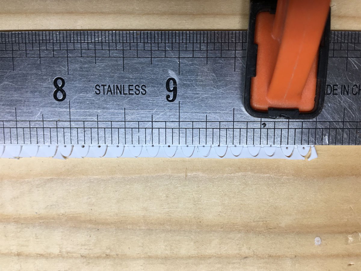
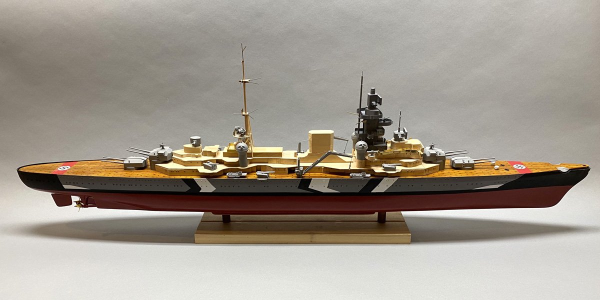
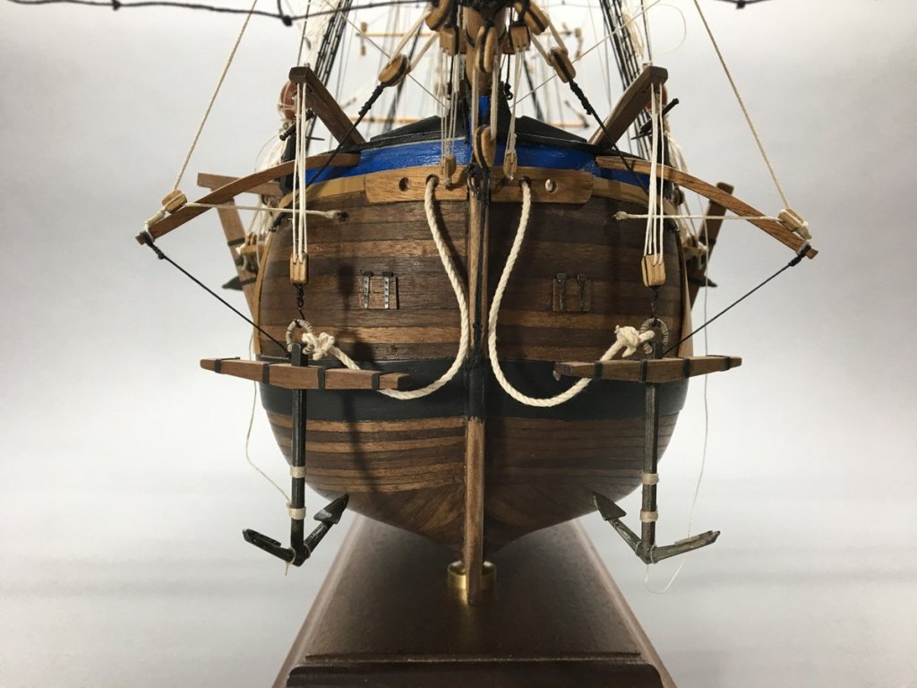
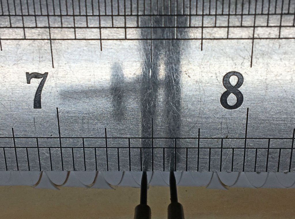
 Portholes on a Battleship? The plans for the Prinz Eugen show 209 portholes on each side of the hull. It seemed odd to me that there would be ANY portholes on the side of a battleship so I Googled "Portholes on WWII battleships?" Turns out that there are a lot of uninformed modelers out there with the same question as me. Here's a good discussion of the topic. https://www.quora.com/Why-did-German-battleships-in-World-War-2-like-the-Scharnhorst-and-Prinz-Eugen-have-porthole-windows-all-over-their-hulls-like-passenger-ships The short answer is that before the end of WWII most battleships had inadequate ventilation and no air conditioning, so they had plenty of portholes for crew comfort. The portholes were all above the heavy armor belting on the lower parts of the hull and had steel covers that could be closed over them during battle. The kit came with 10 bags with about 50 tiny eyelets in each, which I assumed were for portholes. I taped a side view over the hull, marked the center of each porthole with a pin, and started drilling. After 30-40 holes I realized that this wouldn't be accurate enough, so for subsequent holes I clamped a metal straight edge along the pin pricks and used that to keep the holes even. I thought I could just pop the eyelets in the holes and glue them with CA, but they never sat flush with the hull. I ended up crimping each one across the hull with a smooth pair of pliers. In retrospect I should have bought a specialty eyelet crimping tool, but it's too late now. After I finished the portholes on the hull I realized that there would be hundreds more on the superstructure and I was down to my last bag. I ordered 500 more from a doll supply company on eBay. I think that the kit has enough eyelets for an RC model where you probably would not want 418 holes in the side of the hull. It seems that I didn't take any photos of the hull covered with brass eyelets, but this photo after painting gives you an idea what they look like. That leads me to painting the hull.
- 40 replies
-
- 6
-

-
- aeronaut
- kriegsmarine
- (and 2 more)
-
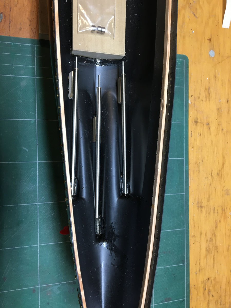
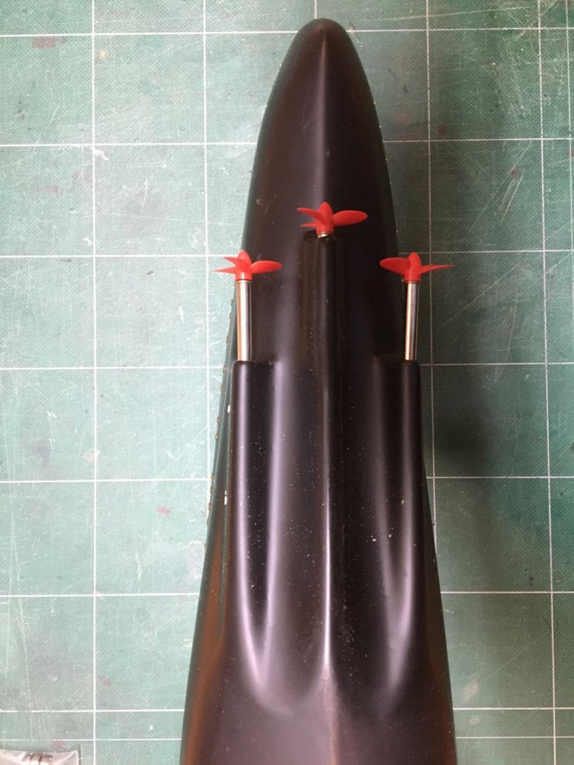
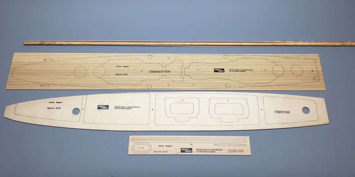
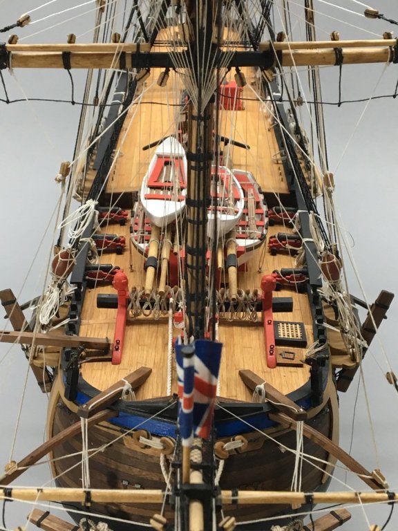
Hull, Deck, Stand, and Propellers I trimmed the excess plastic off the hull with a razor saw, and glued wood strips to the inside edges to support the deck. I decided not to use the bulkheads. I shaped a piece of poplar and glued it inside the hull as an attachment point for a stand. The prop shafts were then glued in place. The kit includes red plastic props for RC . Later I replaced them with scale brass props.

- 40 replies
-
- 8
-
-
- aeronaut
- kriegsmarine
- (and 2 more)
-
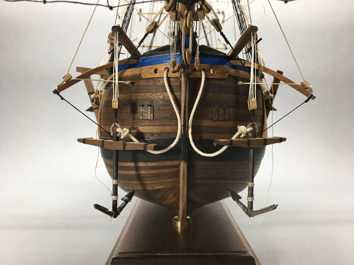
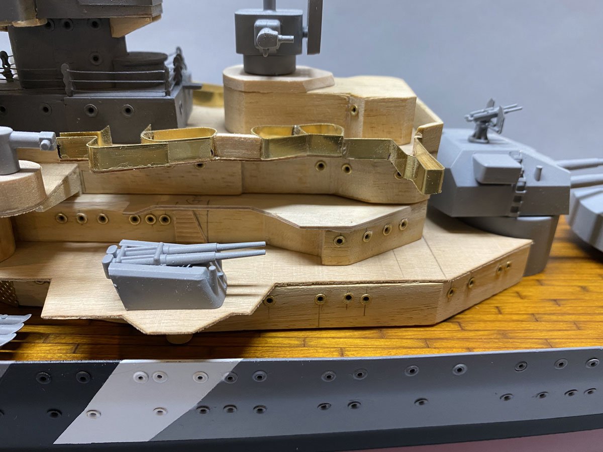
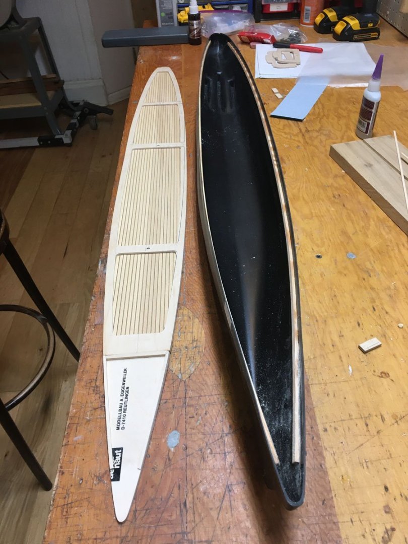
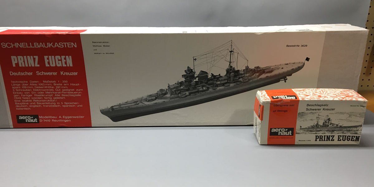
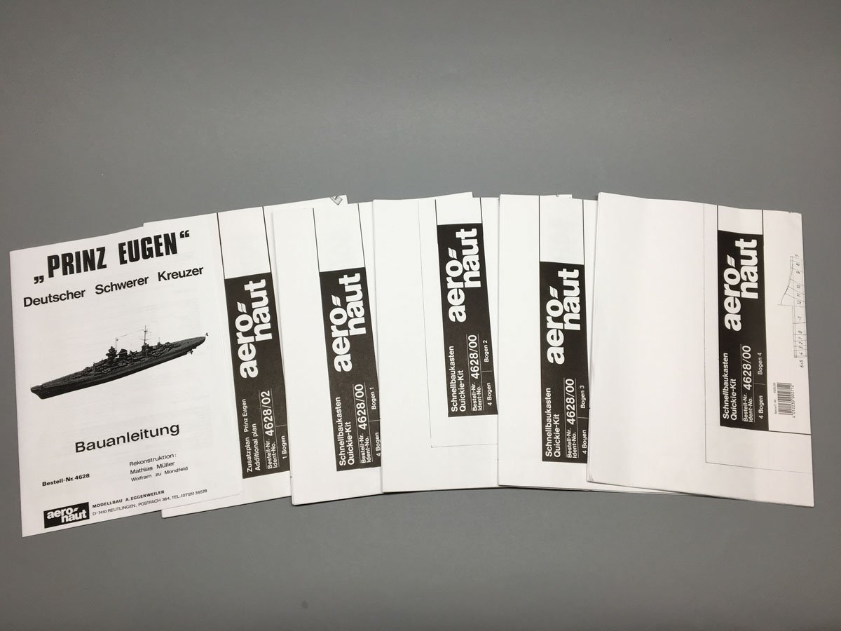
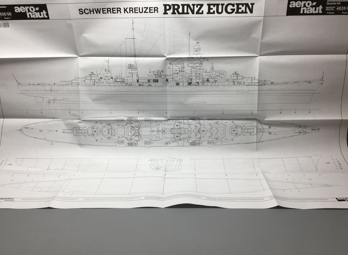
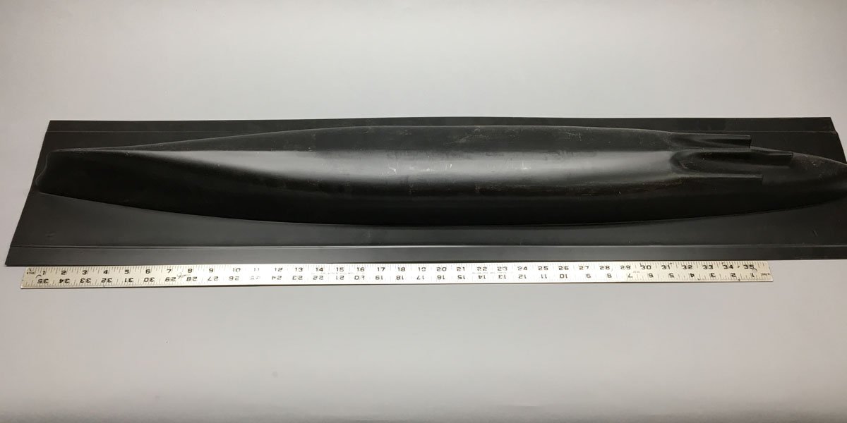
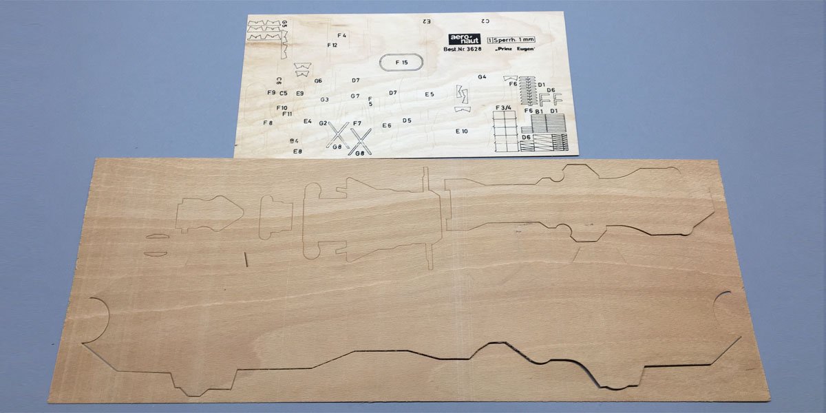
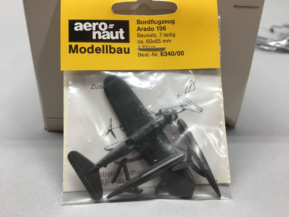
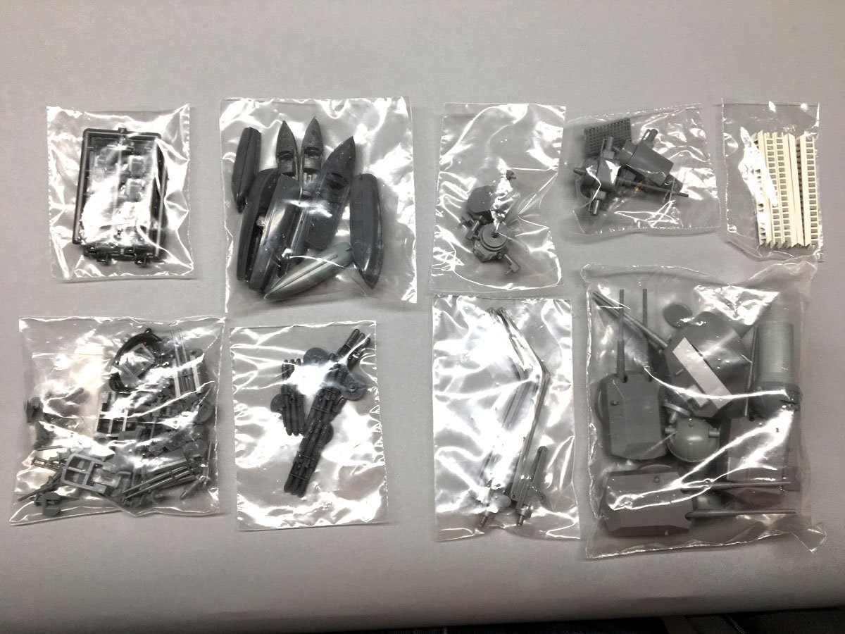
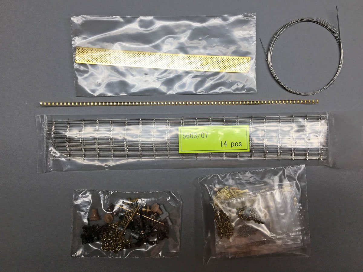
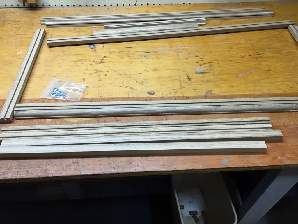
What's in the Box The basic kit is sometimes sold separately from the fittings kit, but one is not too useful without the other. Most vendors sell them together. I got mine from Cornwall Model Boats in England. The kit includes an 8-page instruction manual, all in German, and half of which is a parts list. It's not too useful. The kit also includes 5 pages of full-sized plans. Two of those plans are hull sections in case you want to carve your own hull. They're not too useful either. The other 3 plans include nice 3-views of the ship and lots of details of all the components. A well-made vacuum-formed hull is included. Here it is, all 1170 mm of it. You get to trim off the excess. The kit includes prop shafts, plastic props and rudders for RC, but few details for doing that. I am building for display only. The framework for the deck was pre-cut but printed off center. You still have to cut the bulkheads out of the center with a scroll saw anyway. The decking material looked like it was printed but it turned out to be laminated light and dark strips! However, the scaled planks would be about 2 m wide and just didn't look right. I ended up planking my own deck. More on that later. There are several sheets of thin plywood parts for all the upper decks and fiddly pieces. The parts are stamped but mostly not die-cut. They are jammed together so closely on the sheets that they are very difficult to cut out. I found that the easiest way to cut them out was with heavy scissors. The fittings set include lots of beautiful plastic parts for guns, torpedo tubes, cranes, boats, etc. These parts are almost perfect. There is even a kit for an Arado 196 floatplane. Finally, the fittings kit has a lot of miscellaneous metal parts, and it's not always obvious where they belong. There are about 500 tiny eyelets for portholes, but I used up over 400 on the sides of the hull alone and had to order more. The railings are beautiful but I'm not sure that there will be enough for all the decks. There is a formed brass strip to use for ladders, but the only stairs are plastic and are way off scale. Well that's what is in the box. It seems like a lot, but as I soon discovered there are lots of pieces to a battleship that aren't even addressed in the kit.
- 40 replies
-
- 7
-
-
- aeronaut
- kriegsmarine
- (and 2 more)
-
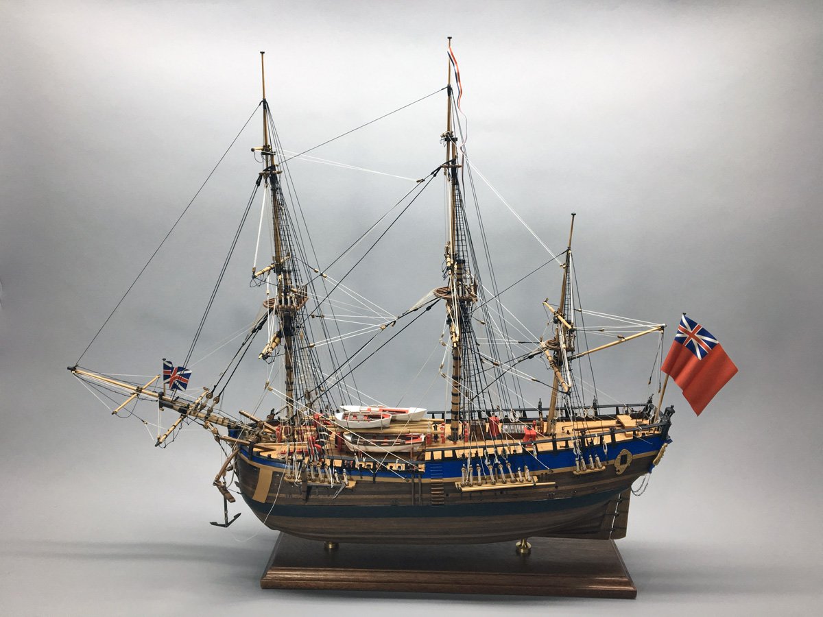
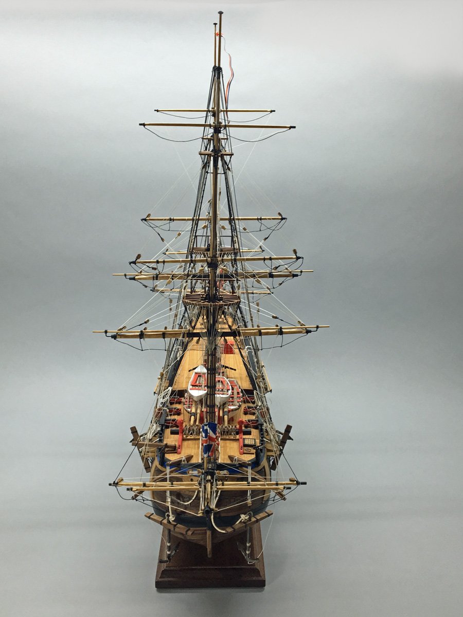
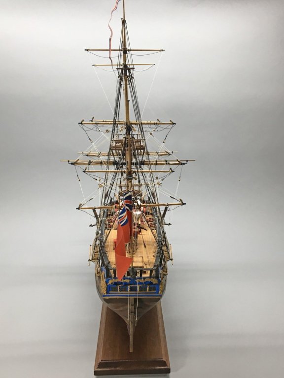
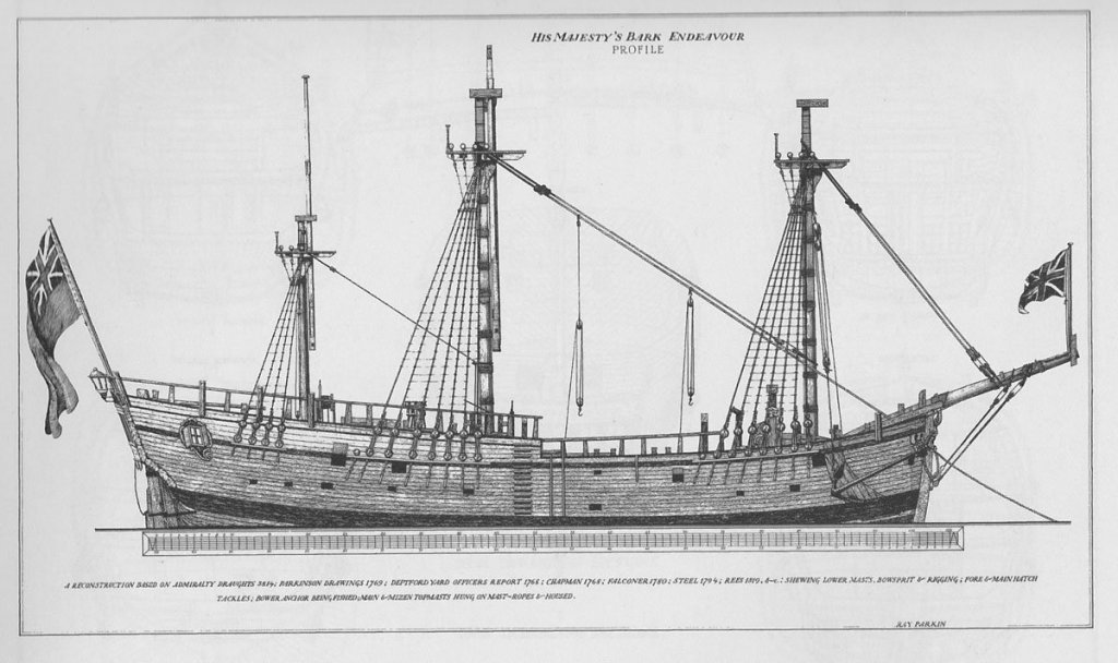
Prinz Eugen, WWII German Heavy Cruiser I am afraid that I haven't been on MSW since I finished my MS Bark Endeavour over a year ago. My wife and I moved from Chagrin Falls, Ohio, USA to Asheville, North Carolina, about 540 miles (870 km) due south. We found a beautiful old stone house in the mountains that has demanded some attention and kept me from building much. Now that we are all social distancing I have had much more free time, and have made a grand start on the Aeronaut kit of the Prinz Eugen (pronounced "Prints You-gen," pardon my German.) I wanted to build a battleship model but there aren't many out there. There are lots of very detailed plastic models, and a few very large, 1:100 scale RC models. German company Aeronaut has several 1:200 scale models of German WWII battleships. They are pricey and there is almost no information about them online. I posted a query on MSW a few years ago and didn't get much information, but I decided to take a chance anyway. I really wanted to build their Bismarck kit because that's the ship that everyone knows. But I had a built-in bookshelf that was 4 ft. (1220 mm) wide and the Bismarck is 1255 mm long, so I bought the Prinz Eugen at 1170 mm. And then we decided to move and leave the bookshelf behind. I finally started the model back in March and am now well underway. This is not your typical MSW model so I wasn't sure if I would keep a build log, but I took some photos on the way and will try to catch up. And I promise to catch up on many of the other logs that I was enjoying in the past.
- 40 replies
-
- 6
-
-
- aeronaut
- kriegsmarine
- (and 2 more)
-
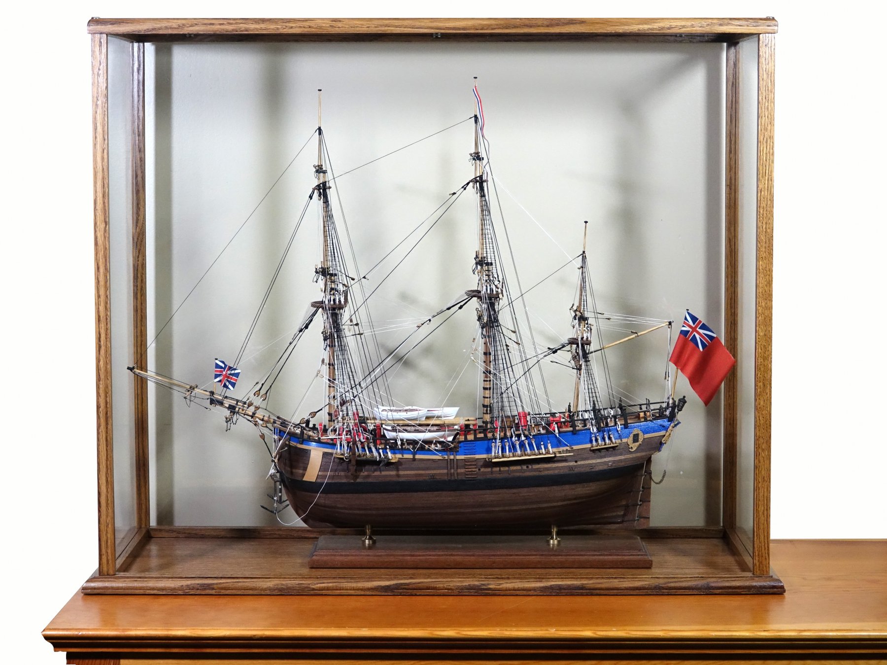
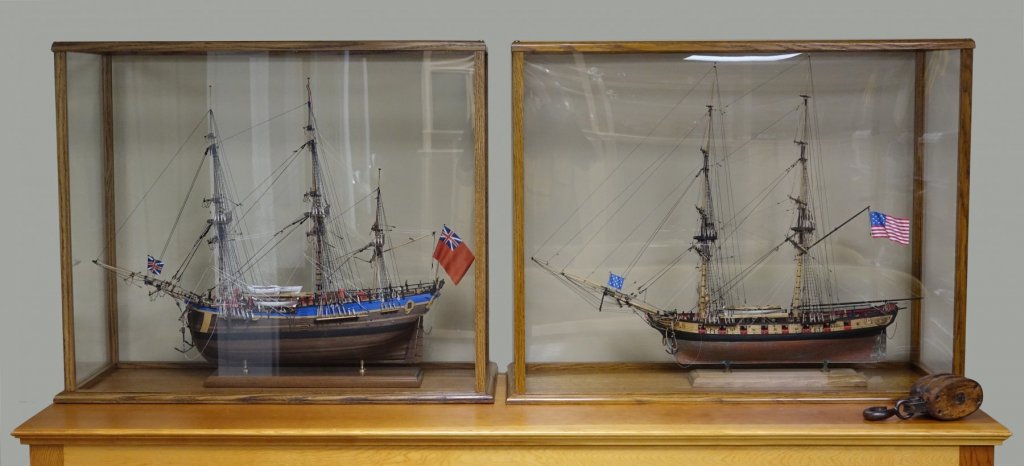
Case Completed I built a case for my Endeavour from scratch in about 3 weeks. It came out very nice and looks good next to my Syren model. They are temporarily displayed in a basement rec room. I don't know where they'll end up when we move. I forgot how hard it is to photograph anything in a plastic case. I tried all kinds of lighting and Photoshop tricks to get rid of reflections. The photo of the Endeavour alone is OK, but the photo of the two ships together is pretty bad. Oh well, I tried. Rod

- 108 replies
-
- 7
-
-
- endeavour
- caldercraft
- (and 1 more)
-
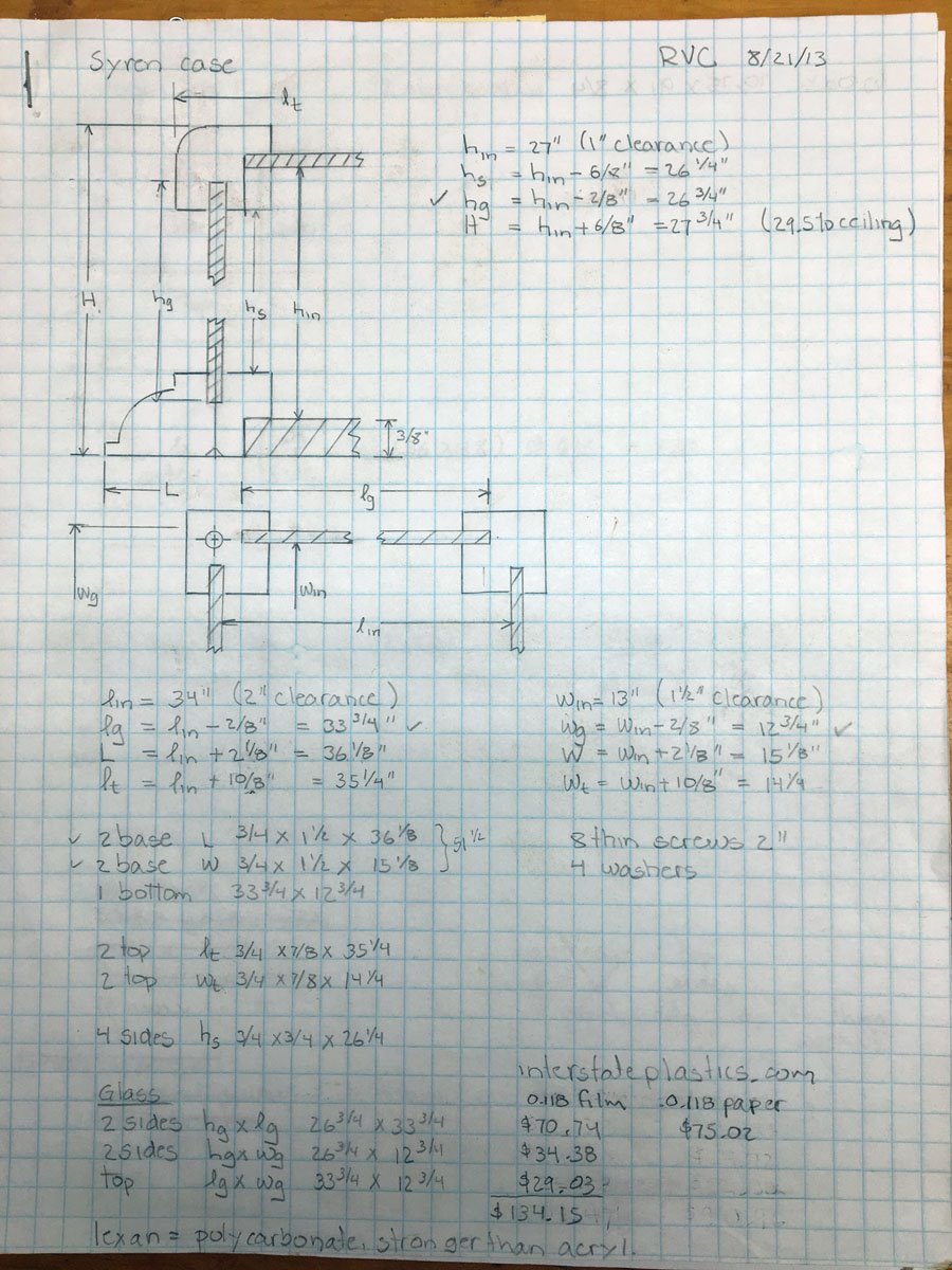
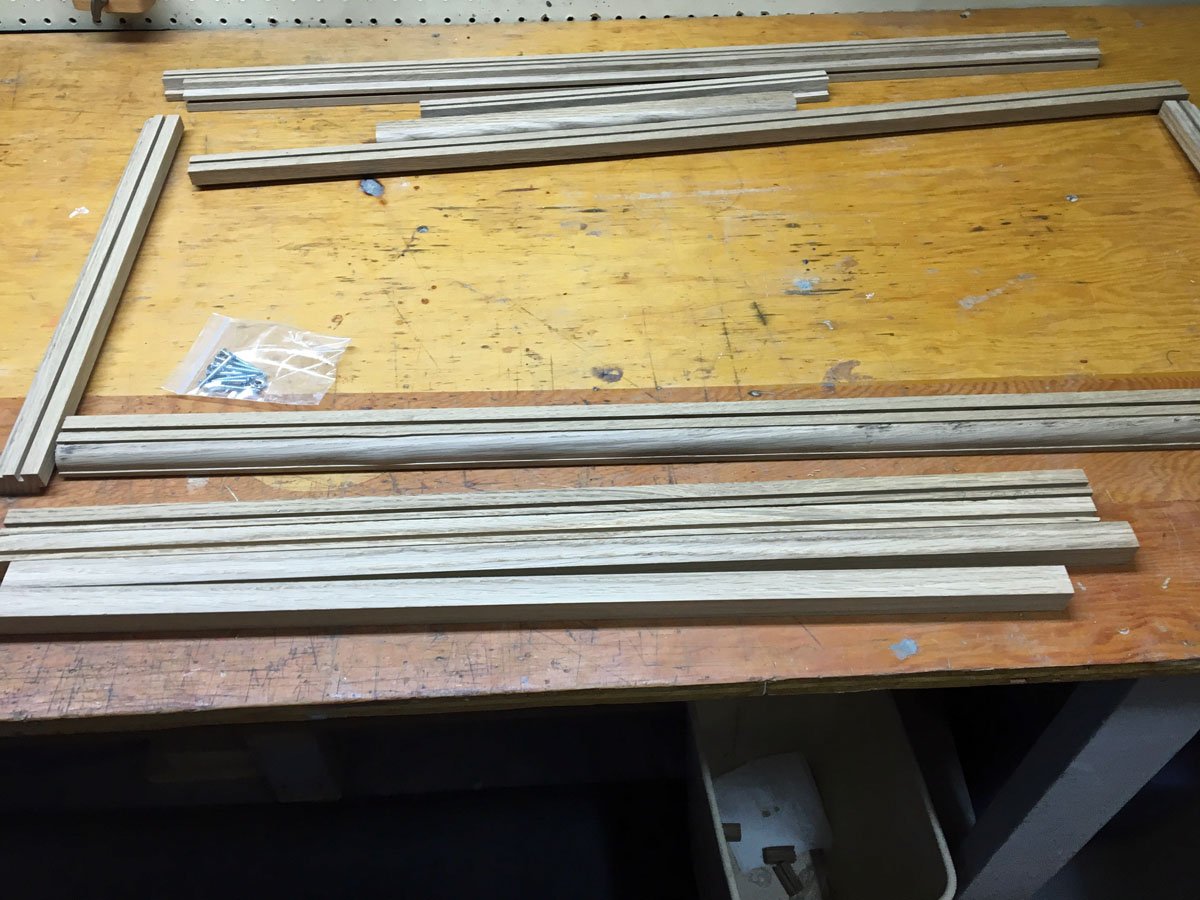
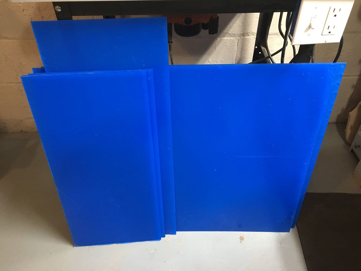
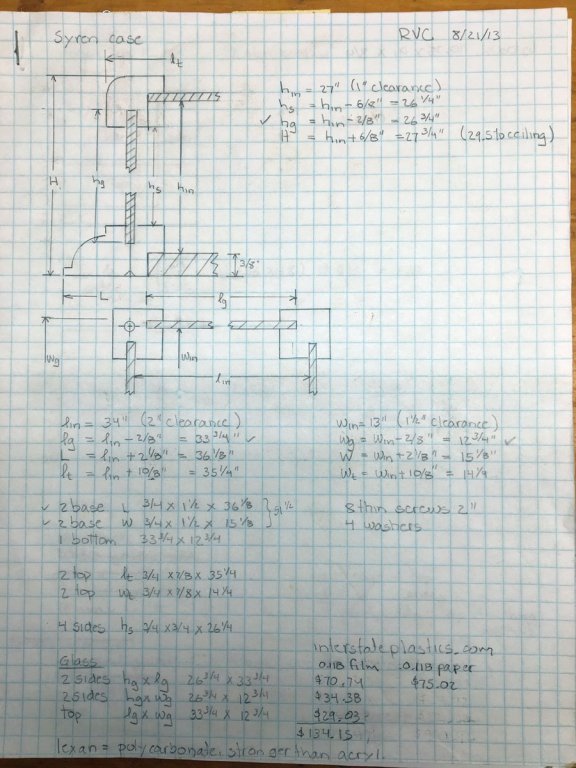
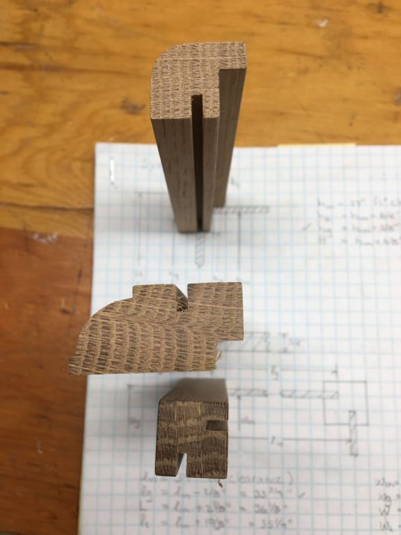
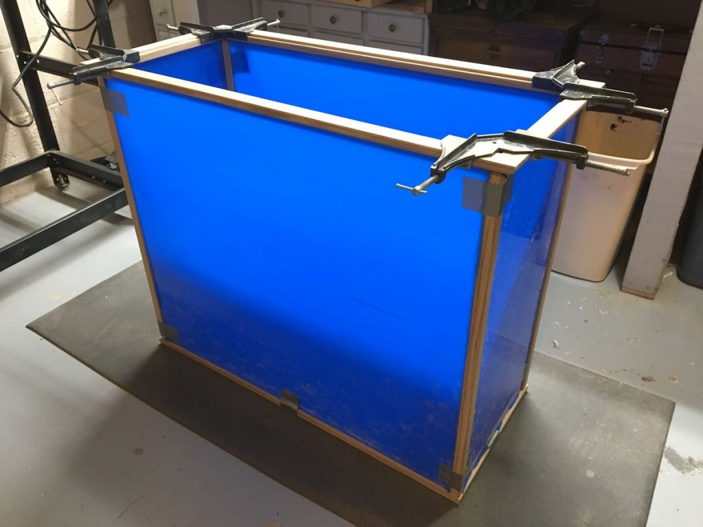
Case Construction Back in 2012 I designed and built a case for a Model Shipways Flying Fish that I built in 1969. I reused the design for my Syren a couple of years later and now again for the Endeavour. Here are the original drawings and calculations for the Syren case. The Endeavour case is exactly the same size but 2 inches shorter. They should look good together. The moldings were cut from 3/4 inch white oak. I cut 1/8" slots for plexiglass with my table saw, the larger rabbet in the base with a dado blade, and the profiled edges on my router table. I made most of the cuts while the wood was much wider to keep my fingers from the blades, then cut the pieces to the correct width at the end. Here are the finished molding pieces before sanding. I ordered 0.118 inch plexiglass cut to size from Tap Plastics in California. For the last two cases I bought large sheets from Home Depot and cut them myself with the scribe and break method. Tap Plastics was about the same cost and a whole lot easier. Today I mitered the top and bottom moldings with a chop saw. I taped everything together to make sure it all fit, then glued up the top frame and later the bottom frame (shown.) I may shoot some brads into the corners for a little extra strength. I will glue a veneered plywood panel into the bottom frame, and screw the Endeavour to it at the end. I will attach the top plexiglass with glazier's points. The side pieces will be held with 8 screws from the top and bottom. Everything can be disassembled by removing those screws. Final photos coming soon.

- 108 replies
-
- 4
-
-
- endeavour
- caldercraft
- (and 1 more)
-
Thank you all for the kind compliments on my model. I know that it is not completely historically accurate, but I am happy with it. I sincerely appreciate all the help and encouragement from my (few) followers. I really could not have done it without all your help. I'll keep watching for Dave Row to finish his beautiful model, and for Fernando to start his! May you both have fair winds and following seas. Rod
- 108 replies
-
- 3
-
-
- endeavour
- caldercraft
- (and 1 more)
-
Dave, I attached my shroud cleats as shown on the plans and they ended up below the rail. I didn't think much about it until I started belaying lines to them and they were out of reach for the sailors. Your shroud cleats look great. Keep up the beautiful work. I'm anxious to see you model finished. Rod
-
Happy New Year Mates! The fireworks in Sydney, Melbourne, Darwin, and every other major city in Australia just look spectacular. I wish I could be there to see them in person. I worked for a small fireworks company while I was in grad school and still love a good show. Here in tiny Chagrin Falls, Ohio we celebrate by lowering a giant popcorn ball from the flagpole in the town square at midnight. I am not making this up. The popcorn shop has been in business in an old gristmill by the falls since 1948. It's not fireworks but it's still fun.

- 108 replies
-
- 4
-
-
- endeavour
- caldercraft
- (and 1 more)
-
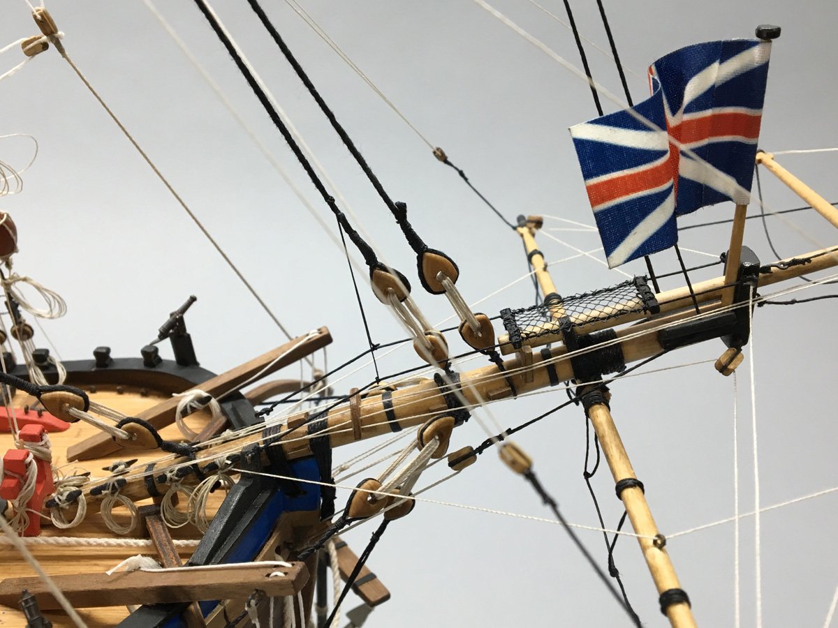
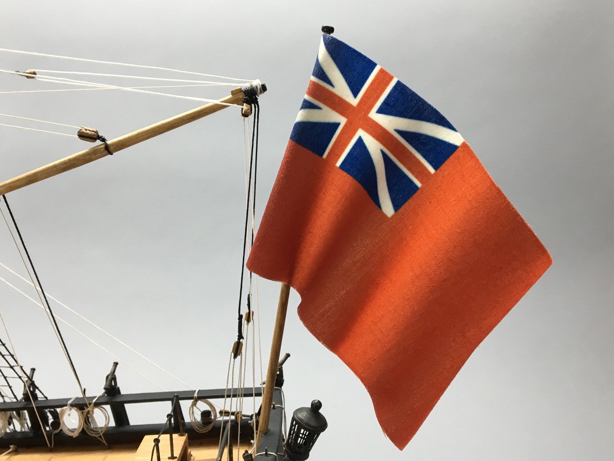
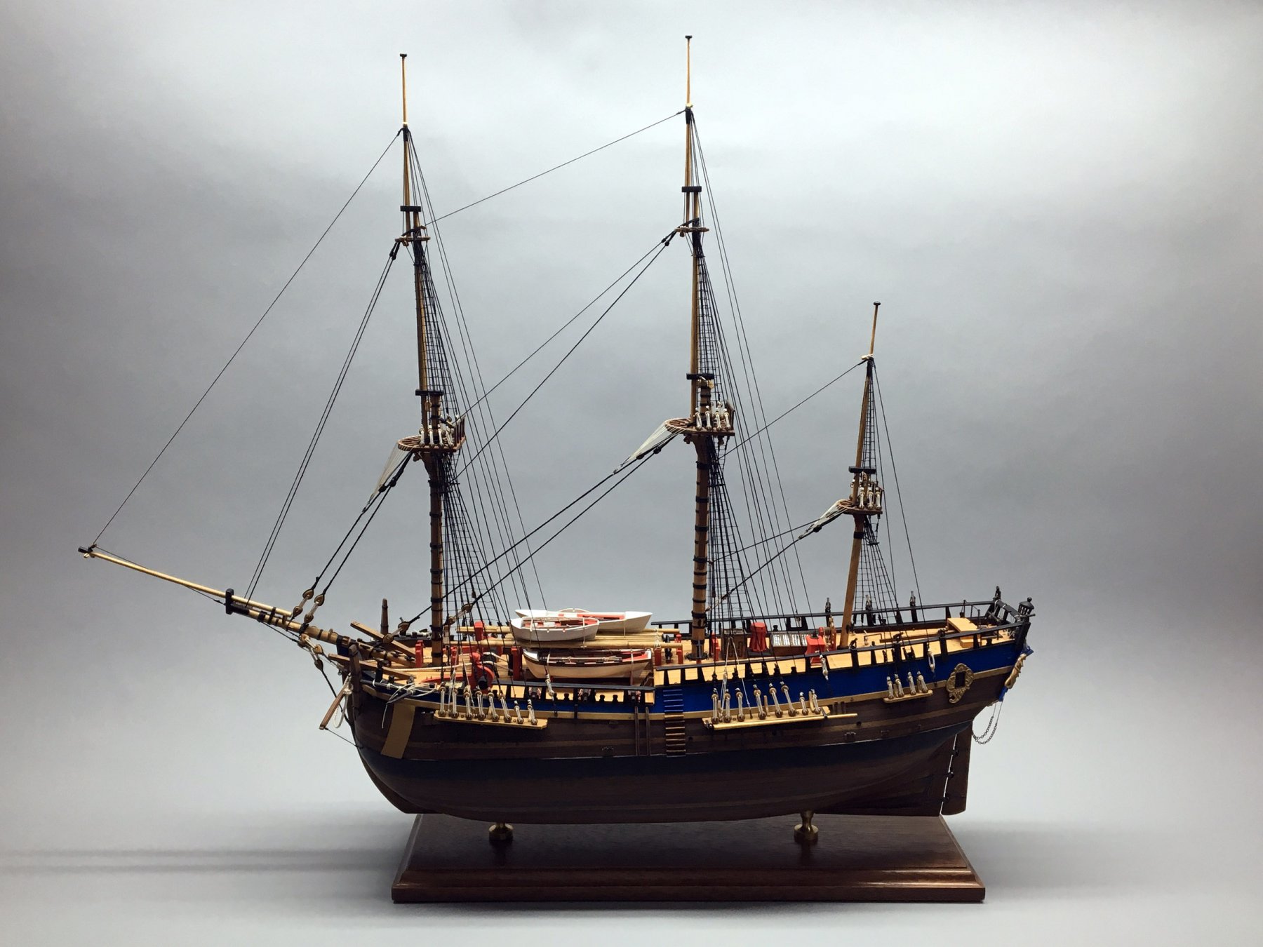
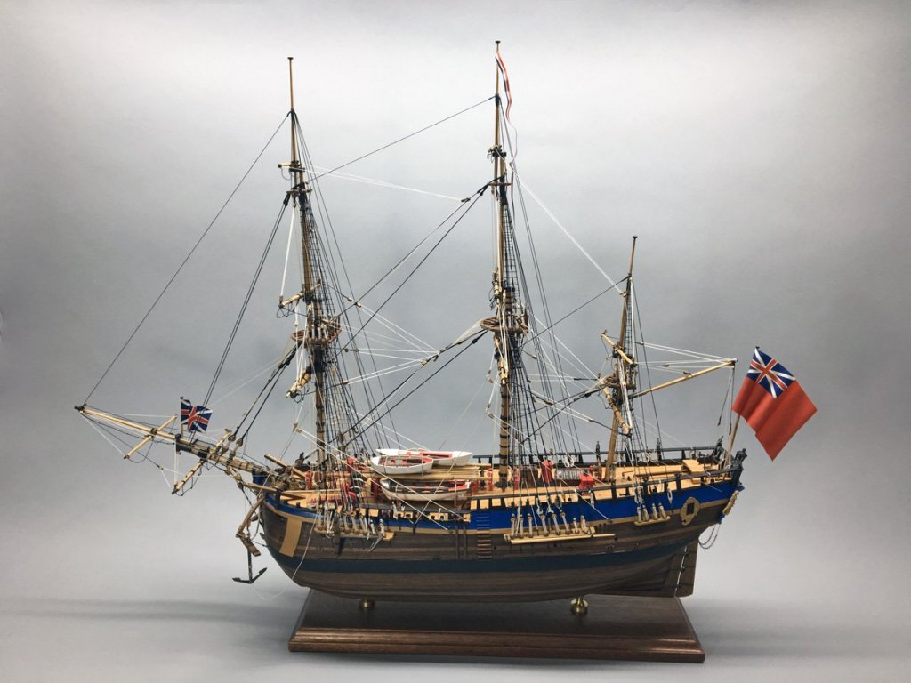
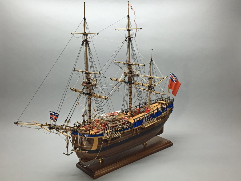
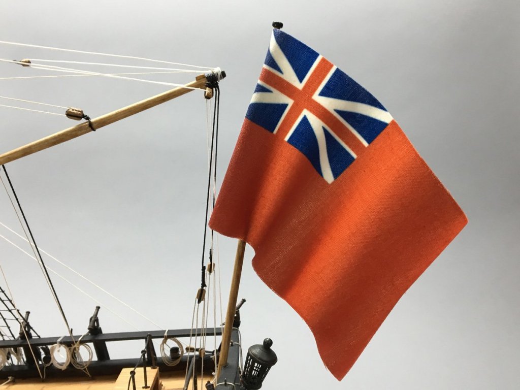
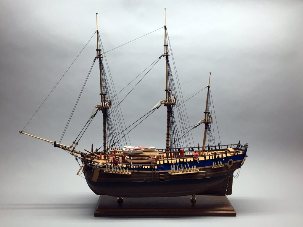
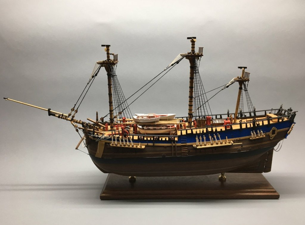
HM Bark Endeavour - Finished! 1 year, 4 months, 10 days, 664 hours I put in a lot of hours since my last major post, and completed the model on Dec. 30. Here are some photos. Anchors Since July I've had the main anchors lashed to the channels. When I attached the second set of anchors I decided that the model would look better with the main anchors hanging. That's how they're displayed on my Syren. After a bit of deconstruction I hung them from the cathead. I like them much better this way. Anchor buoy lashed to the first shroud Fore and main masts Main and mizzen masts Rigging Problems The kit has two plans for running rigging. Plan 7 is mostly lifts and the plan 8 is mostly braces. I started with plan 7 and rigged all the lifts, working fore-to-aft. All of those lines belayed to many of the pins, eyes, and cleats shown on the deck plan. I tried to follow AOTS for attachment points. Then I opened plan 8 and started rigging the braces fore-to-aft. It turns out that plan 8 shows many lines belayed to the same points as plan 7, so I started using unused points nearby. By the time I got to the mizzen mast I had totally run out of deck eyes and mast cleats to belay to. There were line cleats attached to each of the mizzen shrouds, but they were totally unused on the plans. I ended up rigging some of the mizzen braces to those shrouds. They're probably incorrect but it was all I could do at that point. Please don't tell the admiral. Bow with jack Stern with Ensign Flag Problems I bought the jack, ensign, and commissioning pennant from Cornwall Model Boats. They are made by BECC in the UK and are perfectly sized and beautifully made, but he fabric material is very soft and hangs limply. I experimented with several products to make them hold a wavy shape - spray starch, white glue, and polyurethane spray. Nothing worked very well so I ended up washing everything out of the ensign and starting over. Luckily the paint is waterproof. I ended up putting a couple of coats of clear shellac on each flag, crumpling them up, and putting them aside to dry. Then I held them in front of my electric workshop heater and worked them into shape. Even the easy things are hard. Case I designed and built a case for an old Model Shipways Flying Fish a few years ago, and later scaled the design for my Syren. The Endeavour has nearly the same height and width as the Syren but is 2 inches shorter, so this rescale was easy. I have ordered five pieces of plexiglass cut to size for an Endeavour case and will start cutting wood today. It looks like my wife and I will be moving to Asheville, North Carolina soon, so I need to get this ship in a case before the move. Pictures to follow.


- 108 replies
-
- 11
-
-
- endeavour
- caldercraft
- (and 1 more)
-
Dave, Thank you very much for the booklet. It's beautiful on its own and should be a big help with the remaining construction. Rod
- 108 replies
-
- 1
-
-
- endeavour
- caldercraft
- (and 1 more)
-
Pat, I've been through the AOTS book many times now and completely overlooked the deck plan on pages 120-121, maybe because it's sandwiched between many pages of sail rigging. That plan will help a lot, but I'm afraid to look to see what I've done wrong already. At least the spiritsail yard brace pin 11 isn't used yet. Rod
- 108 replies
-
- 2
-
-
- endeavour
- caldercraft
- (and 1 more)
-
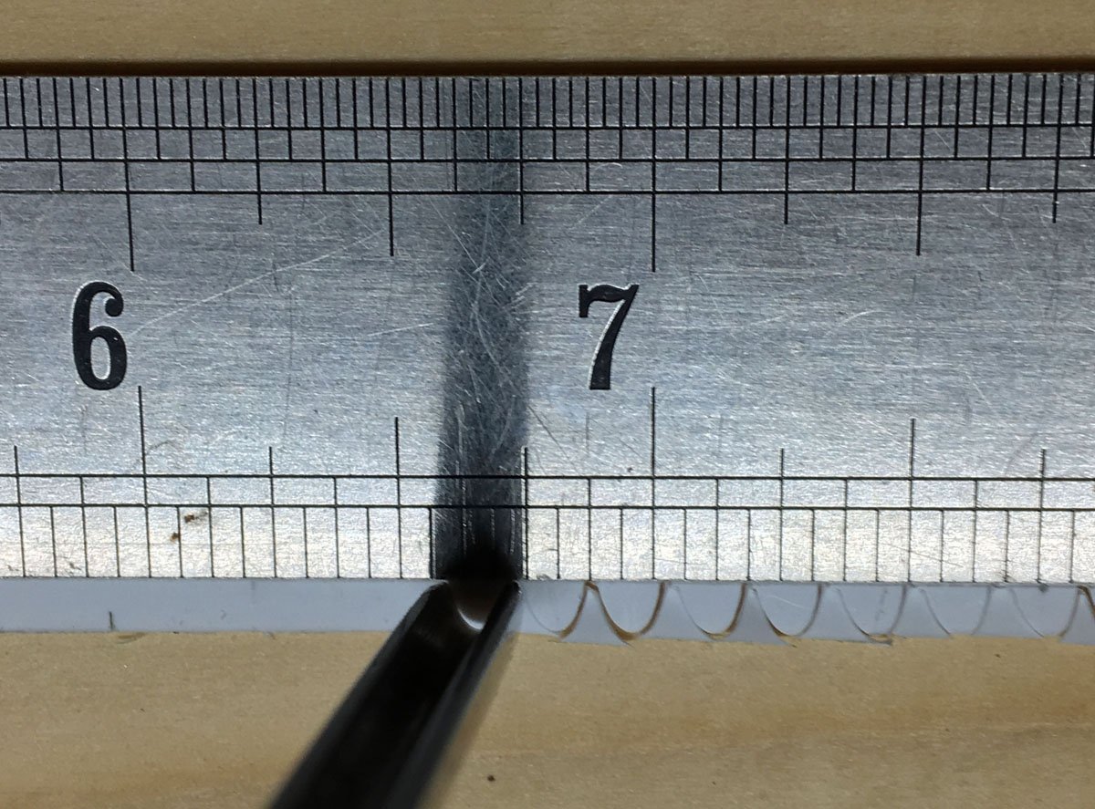
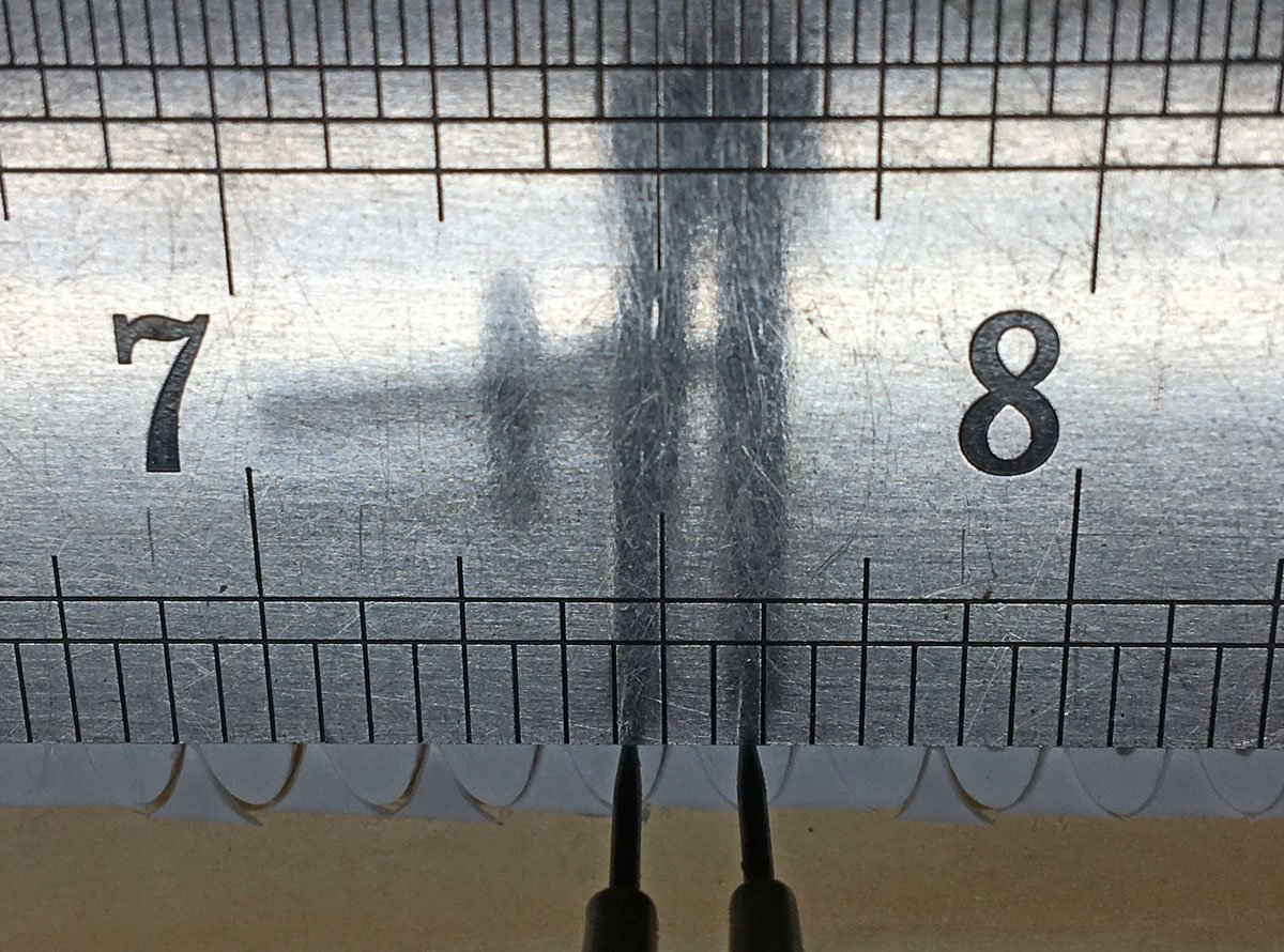
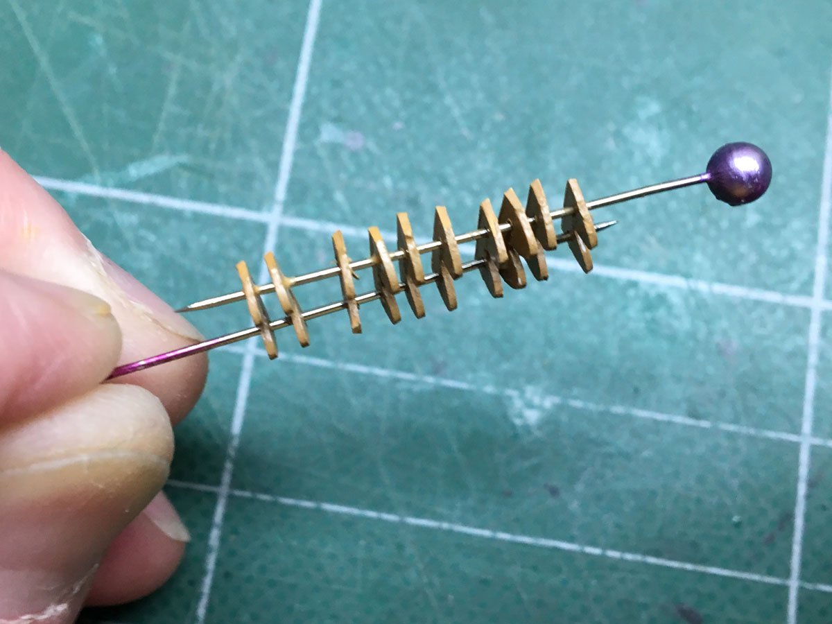
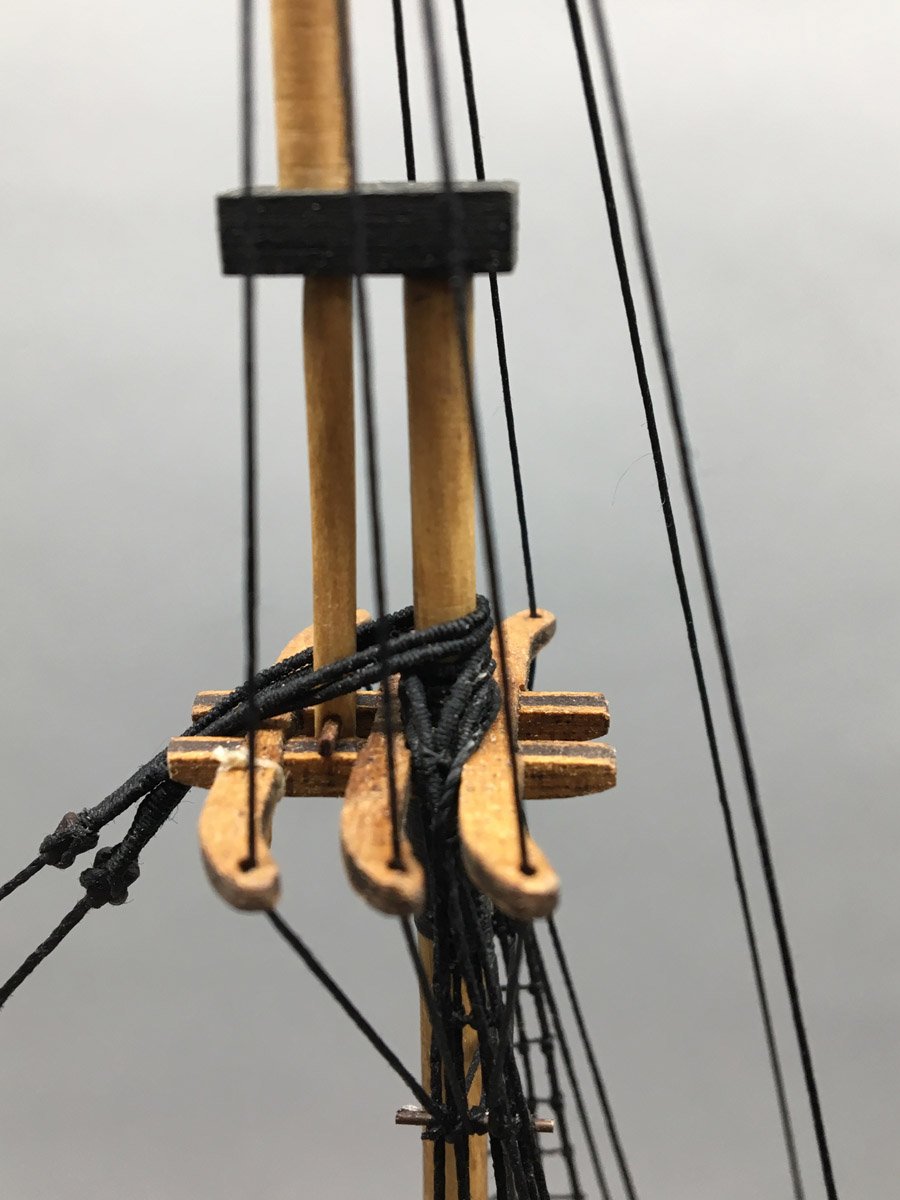
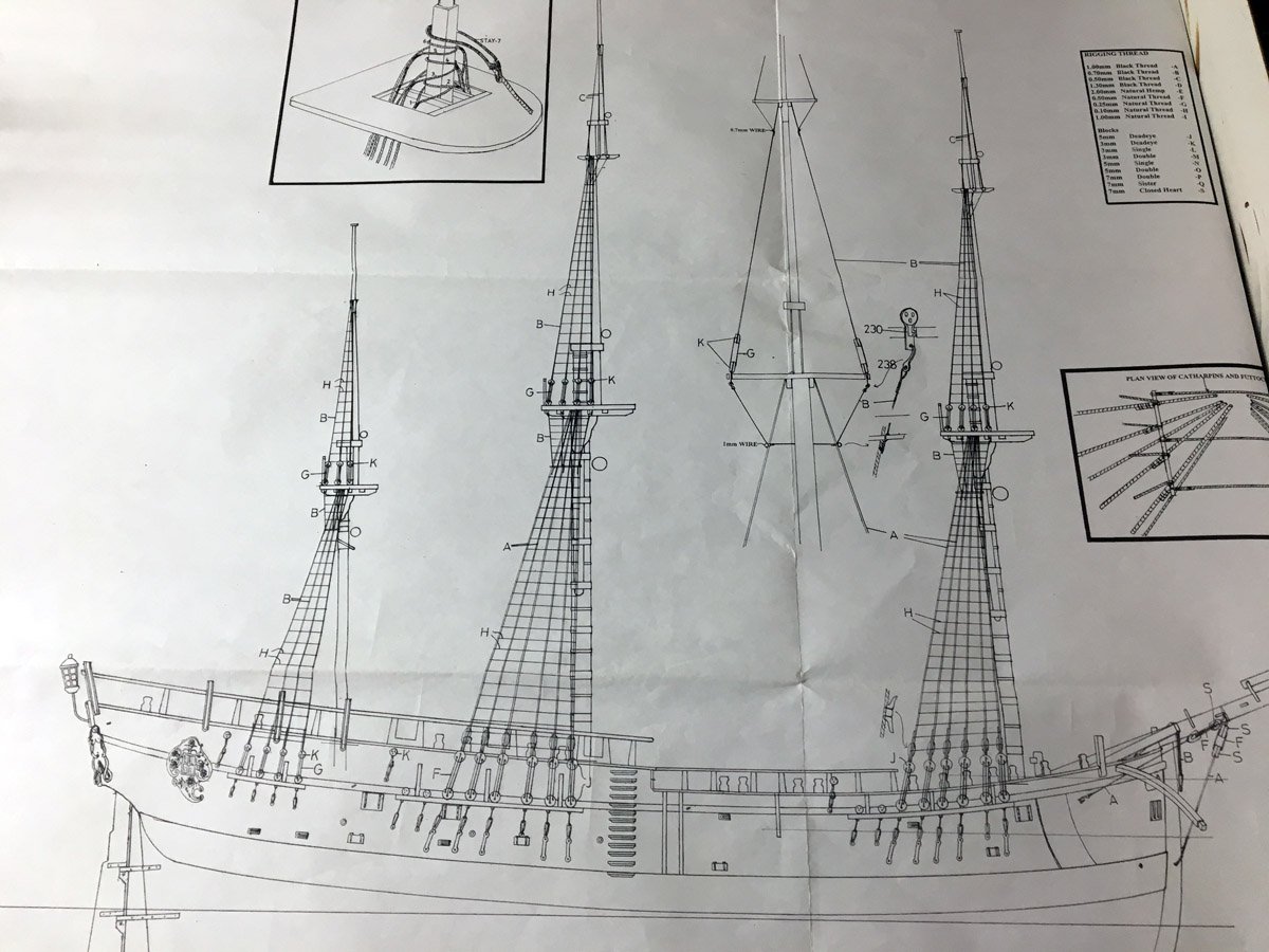
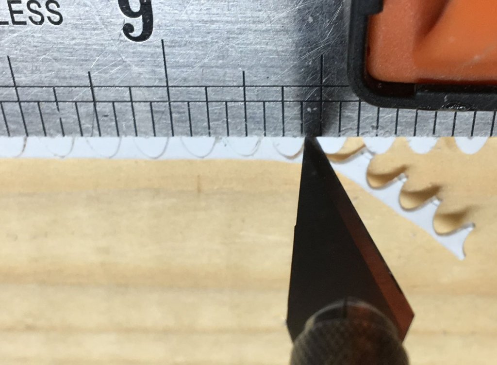
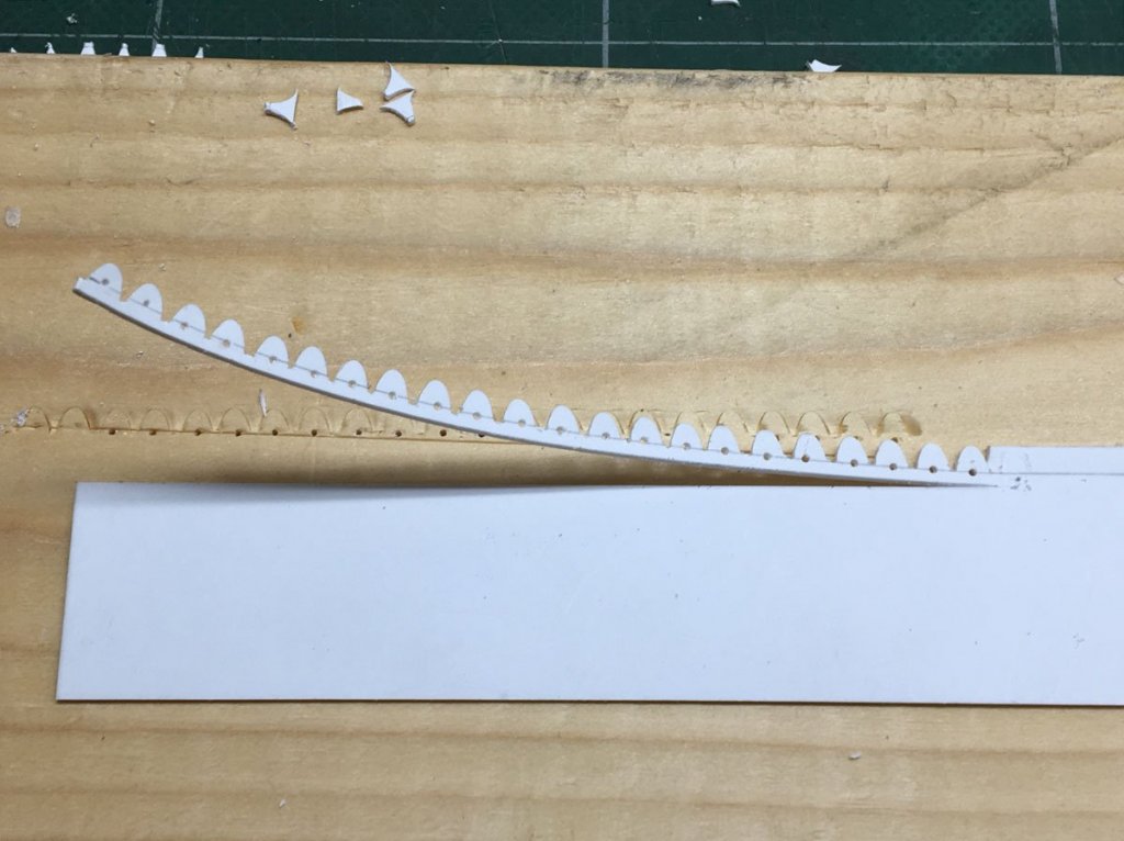
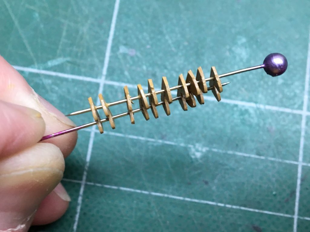
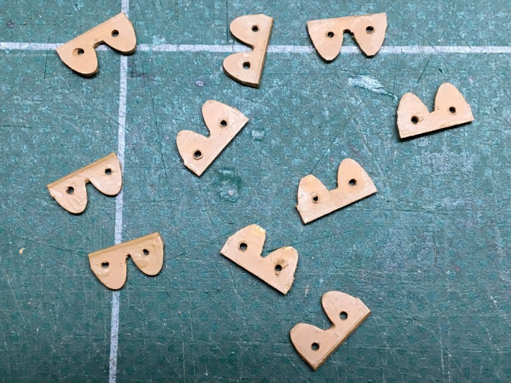
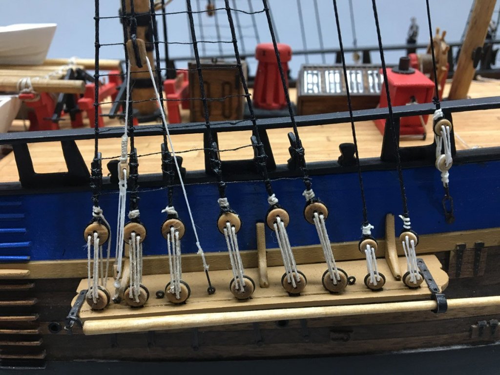
The Parrels of Ship Modeling I decided to go ahead and loft all my yards, with the mains on slings and all else on parrels as discussed earlier. I've been using the PE brass parrels supplied with the kit, painted wood color. They're a little thin but look pretty good. I'll get some pictures up soon. Anyway, when I got to the final yard (the mizzen top) I ran out of parrels. I don't have a 3-D printer like Dave Rowe or a milling machine like Pat Banyan, so I needed another clever way to make parrels. Here's what I came up with. I started with some styrene sheet left over from my Arleigh-Burke. It was exactly the same thickness as the PE brass parrels, 0.5 mm. I clamped it down with a straight edge 3 mm from the edge, and used a 3 mm gouge to cut a series of humps along the edge. The humps are a little hyperbolic. If I were to do this again I'd try sharpening a piece of brass tube to cut circular humps, but this looks OK. I used an X-acto knife to cut the gaps between the humps, and used dividers to mark holes exactly 4 mm apart in each pair. I drilled the holes with a Proxxon drill, and sliced off a strip of parrels when I was done. I painted the strip (and my fingers) wood color, sliced off the individual parrels with a chisel, and stacked them on 2 pins to touch up the ends. Ta da!


- 108 replies
-
- 2
-
-
- endeavour
- caldercraft
- (and 1 more)
-
All, I took a little road trip with my wife and just noticed that there were some new posts here. I do have Marquardt's AOTS, and while it is great for showing where lines are attached on the yards, etc., it doesn't really show where they belay to. Does Mr. Marquardt have another rigging plan that I am unaware of? Rod
-
Pat, Thank you for the quick response! I was just sitting at the dining room table with my two rigging plans and colored pencils to try to see where everything goes, and now I have a more general question. Should the fore and main masts be rigged symmetrically? i.e., if a line from the fore yard goes to a cleat on fore shroud #1, should the corresponding line on the main yard go to the cleat on main shroud #1? It seems likely to me, but there are a couple of instances on my plans where the yards on the fore and main masts are rigged very differently.
-
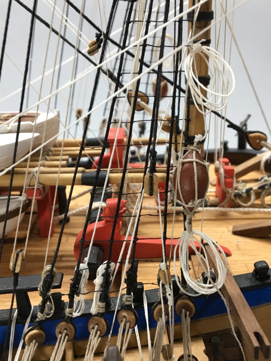
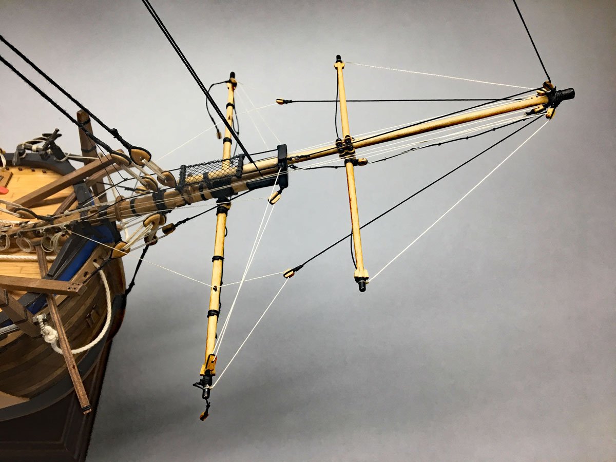
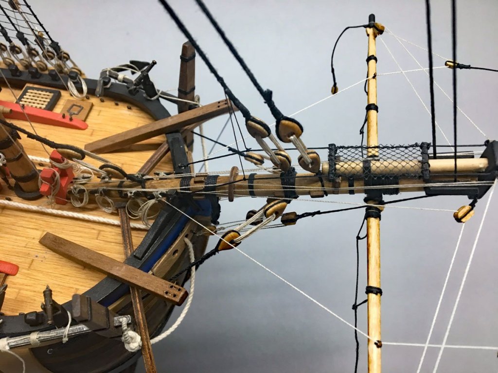
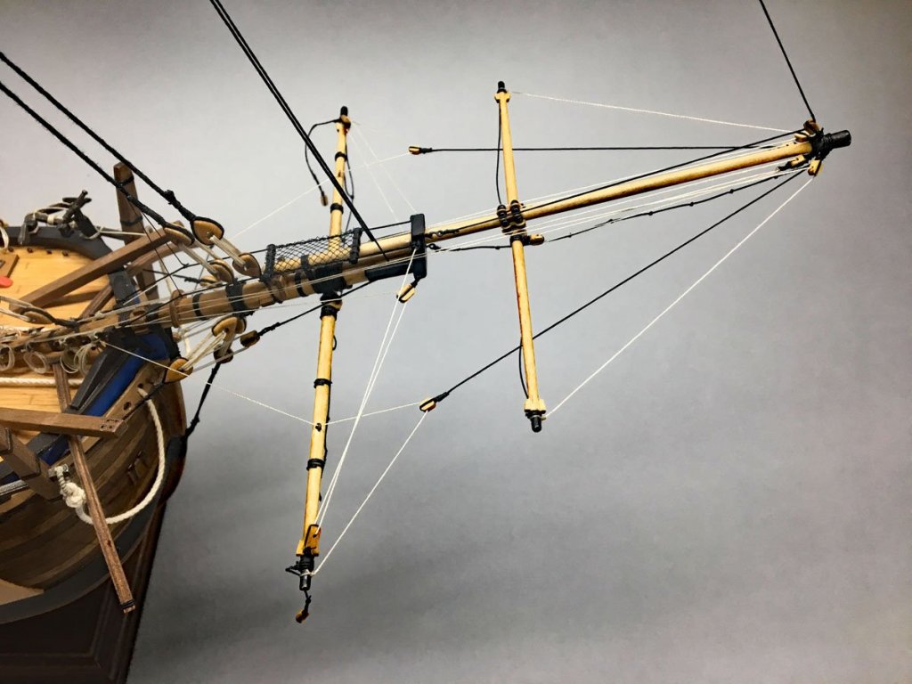
Spirit, Fore, and Main Yards Here are some photos of my progress on the yards, as promised. Spiritsail and spirit topsail yards are installed and mostly rigged. The Caldercraft kit did not include any reference to the netting or any material for the same. I thought that I might have a scrap left over from my Syren, but alas, none in my parts box. So I went to the local fabric store where I had to buy 1/4 yard of netting at the outrageous price of 28 cents ;^) The fore and main yards are lofted, and the foreyard is mostly rigged. It was really tricky getting the jeer blocks lashed in place. They hang freely from lashing around the mast that hangs on two little wood bumps attached to the mast. The blocks want to dance around and the lashing wants to fall off the blocks. I hung some spring clamps from the blocks to keep them pointed downwards, attached some electrical clamps to the jeer block ties to hold them at the right position, and put a pin into the mast at the top of the bump to keep the lashing above it. A picture would have helped but I was too frustrated to get the camera. Anyway I got them done. Here's where the fore leech and bunt lines are belayed. I'm still not sure where to belay the main lines.


- 108 replies
-
- 2
-
-
- endeavour
- caldercraft
- (and 1 more)
-
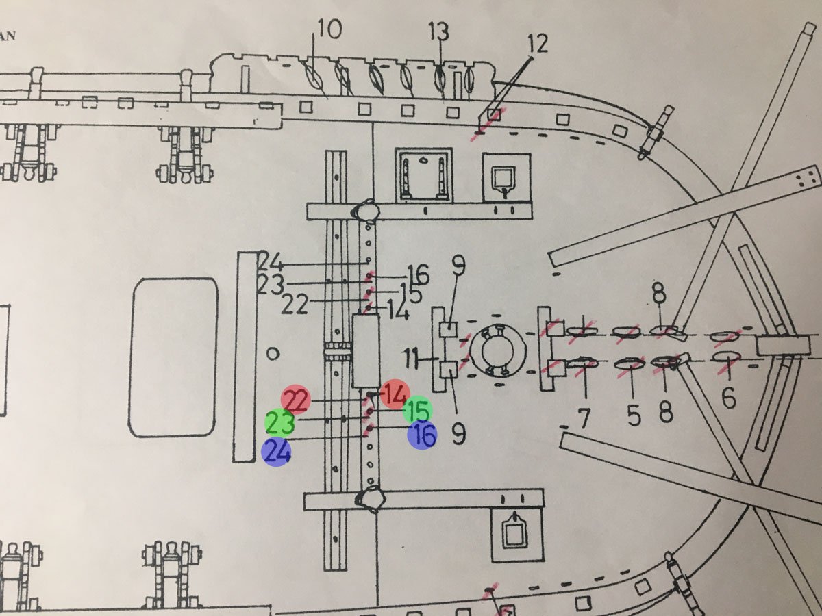
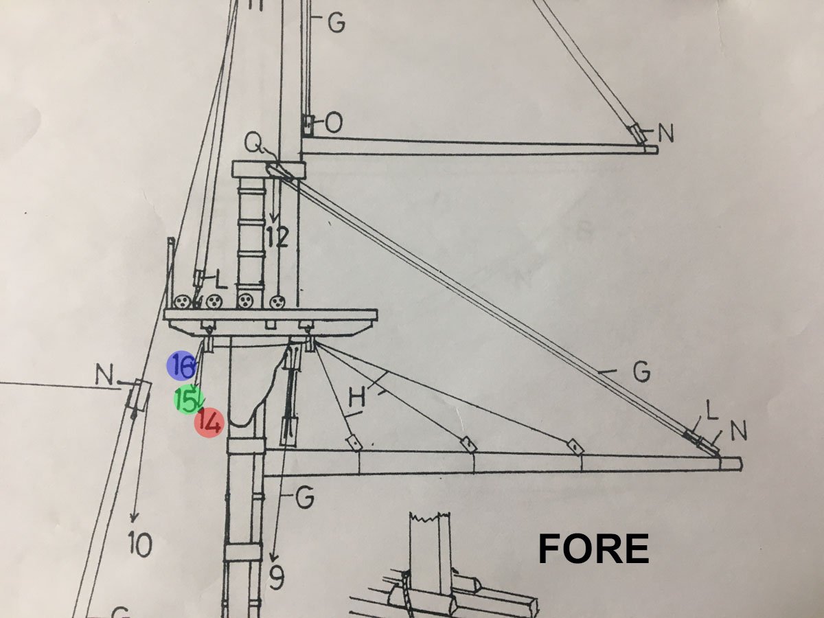
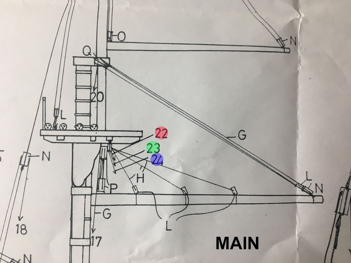
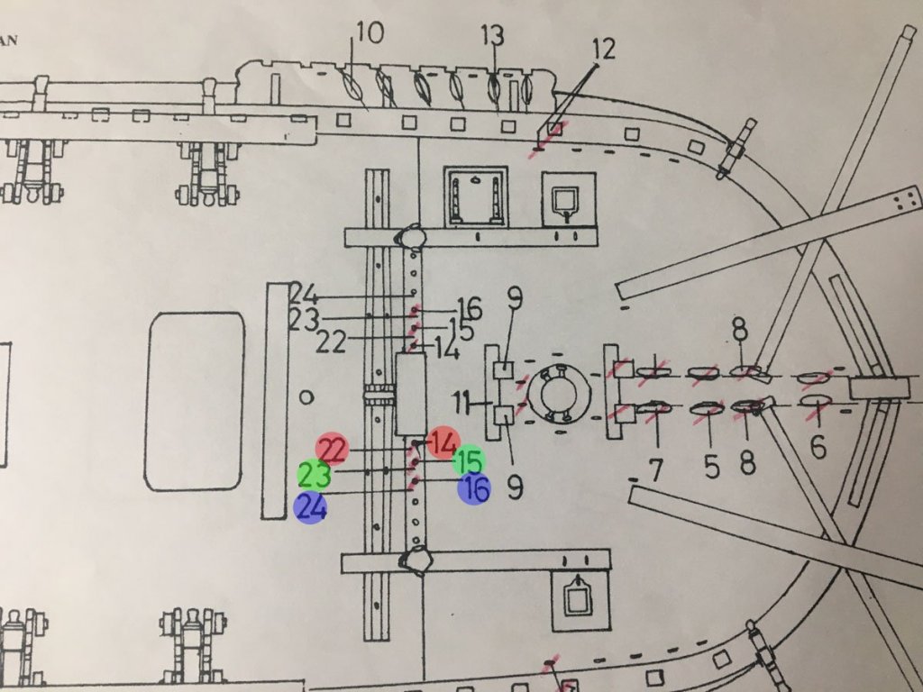
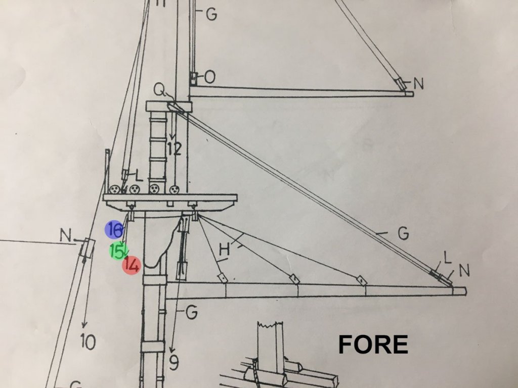
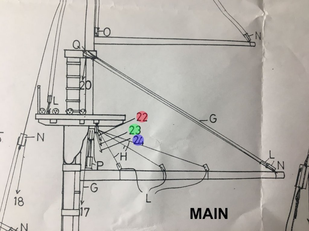
Running Rigging Question I am pretty much done with the spiritsail and spiritsail topsail, and have lofted the fore and mainsails. I promise to get some photos up later today or tomorrow. I rigged the leach and and bunt lines on the foresail but have run into some probable errors on the Caldercraft plans and need some advice on how to proceed. The deck plan shows where the lines attach. The foresail leach and bunt lines, 14, 15, and 16, (red, green, and blue) attach to the pin rail ahead of the winch. Seems reasonable to me. But the leech and bunt lines on the mainsail, 22, 23, and 24, appear to go forward and attach to exactly the same pins as the foresail lines. That does not seem right. I suspect that they should lead aft across the top, and then down to the bitt just abaft the mainsail. I mentioned previously that the plans did not show any belaying pins in the bitts. I did add some, but maybe not enough. If you've completed this step, please let me know what you did with these lines. Many thanks.
-
I like what you did with the oar handles. The notches in the gallows make a lot of sense. I wish I'd thought of it. Rod
-
Pat & Dashi, Thank you so much for the information. I was not aware of the books by Peterson or Steele. They look like excellent references that I should have been looking at all along. I attached the spirit yards and some of their rigging last week, but am currently visiting my son in North Carolina. Thus, no progress for awhile. Rod
- 108 replies
-
- 1
-
-
- endeavour
- caldercraft
- (and 1 more)
-
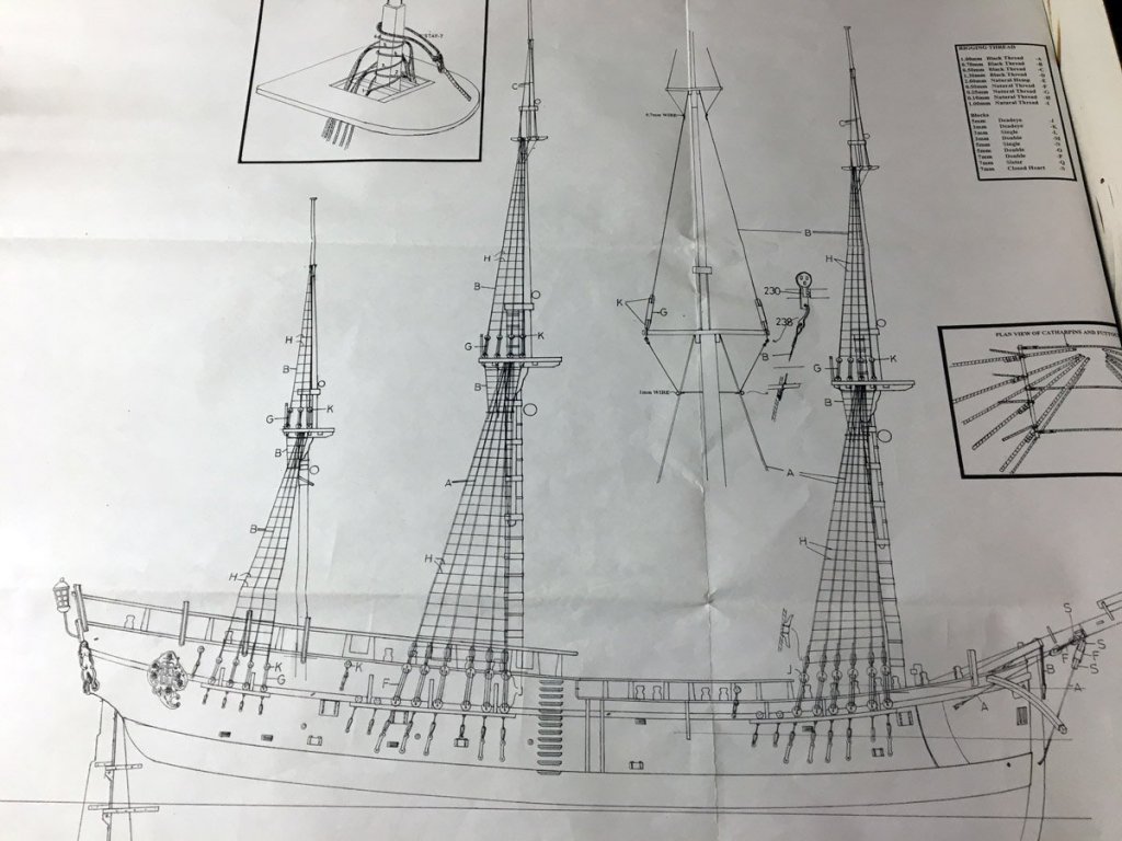
Parrels Question So I am ready to loft some yards and am unsure which ones should have rolling parrels. The Cladercraft plans only show parrels on two yards - the main topsail yard and the spirit topsail yard. Dave Row's build log shows rolling parrels just about everywhere except on the top gallants. I can't quite tell where Pat Banyan has rolling parrels. From what little I've read, main yards were usually lofted into place and left there. I can't imagine how rolling parrels could roll past all the bands and hoops on the main mast anyway. So I'm thinking: Rolling parrels on the spiritsail top Sling on the spirit yard Slings on the top gallants Rolling parrels on the top yards Slings on the main yards Crossjack and mizzen topsail ?? Beads on the gaff without spacers Please let me know what you think, and feel free to correct any incorrect terminology. This is not exactly my area of expertise. The beads in the Caldercraft kit look pretty good. The spacers are PE brass. I've painted them wood color but haven't strung them up yet to see how they look. I have a feeling that I may end up making my own. Sure would be nice if Chuck Pissaro offered some laser cut ones!
- 108 replies
-
- 1
-
-
- endeavour
- caldercraft
- (and 1 more)
-
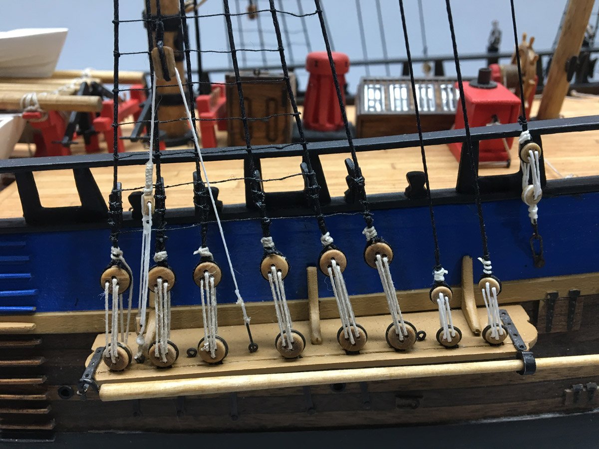
Standing Rigging Complete - 1 year, 2.5 months, 576 hours Just 2 weeks since my last post and I have 2 more layers of masts and rigging in place. I'm about ready to start lofting yards. The top gallants were relatively easy. I ran out of Caldercraft line after the main deadeyes and replaced it with white linen from Bluejacket Shipcrafters for the top deadeyes. It is much nicer line - no fuzz and exactly the diameter it claims to be. It is whiter than the line that I used on the crows feet and the lower deadeyes, but I'm OK with it. The top shrouds and ratlines were just like the mains - just fewer knots to tie. The breast backstays were complicated to set up. With three blocks and a hook it was hard to decide what to tie last to maintain tension. I set up all the blocks first and tied the hook last, probably exactly the opposite of real life, but everything is taut.

- 108 replies
-
- 2
-
-
- endeavour
- caldercraft
- (and 1 more)
-
Lower Standing Rigging Complete, 1 year, 2 months, or 542 hours Back on August 30 I threatened to quit when I got got all the lower standing rigging in place like this, and here I am. But last night I attached the top masts so it's too late to quit. Then looked at the plans to see what happens next. Basically I just have to do the standing rigging all over again, albeit with fewer lines. I can hardly wait.
- 108 replies
-
- 4
-
-
- endeavour
- caldercraft
- (and 1 more)
-
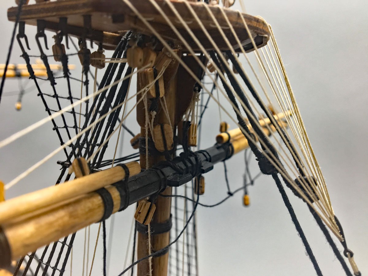
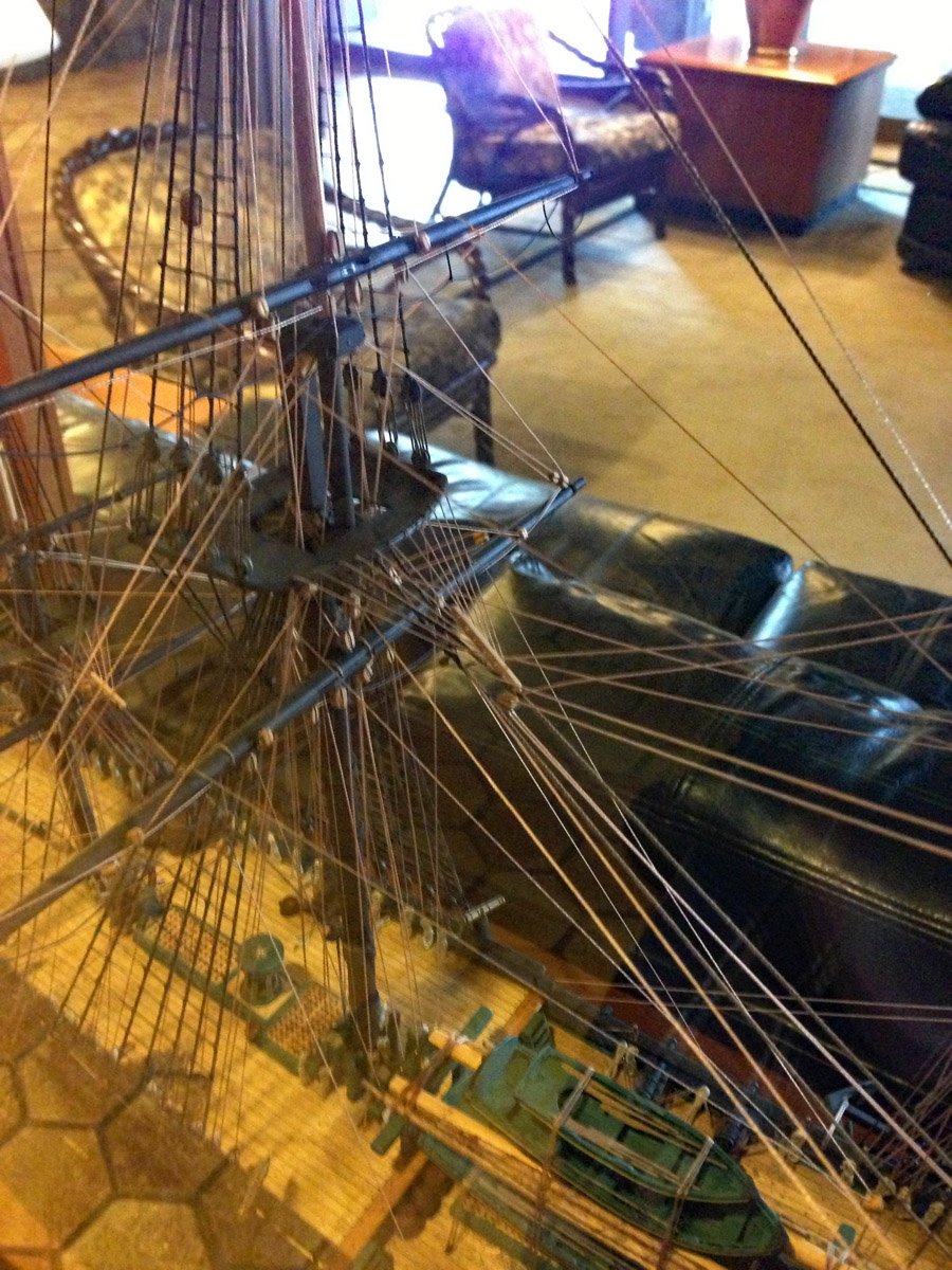
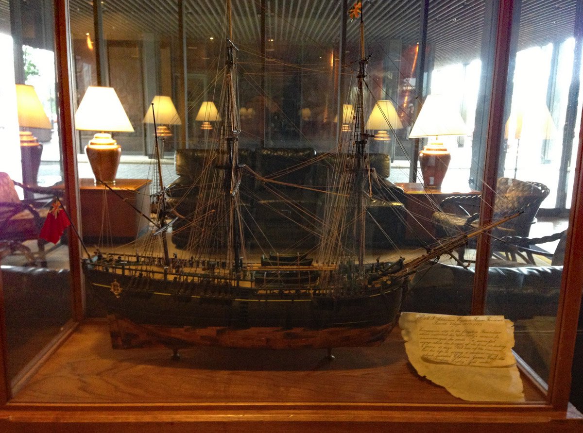
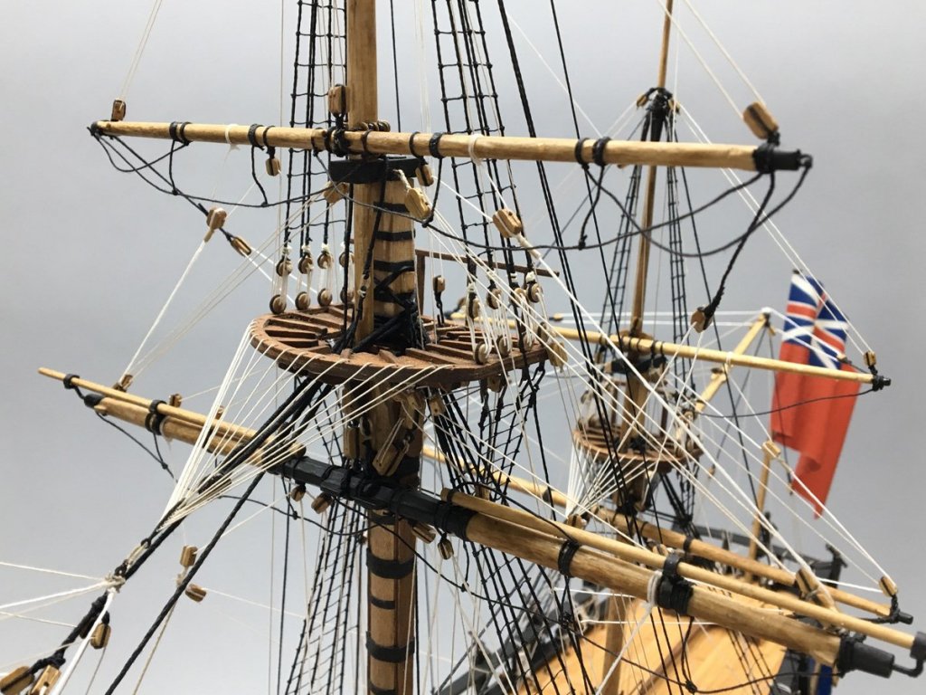
Crows Feet My wife and I were in Alaska in 2013 and stayed in a nice hotel in Anchorage. They had a beautiful model of the HMS Resolution in a case in the lobby. I had never seen a ship with crow's feet before (the radial lines from the back stays to the tops). I was intrigued and took a couple of (poor) photos. Three years later I was searching for something to build and I looked for the Resolution. No luck there but I found this kit of the Endeavour. So now I've spent 500+ hours on the Endeavour just to rig crows feet, that took about an hour tops to make. But I love them.


- 108 replies
-
- 3
-
-
- endeavour
- caldercraft
- (and 1 more)
-
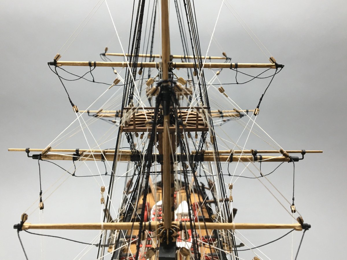
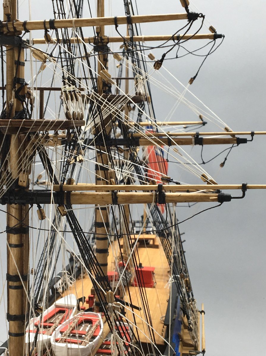
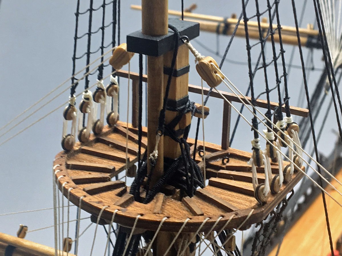
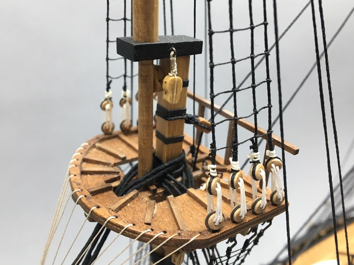
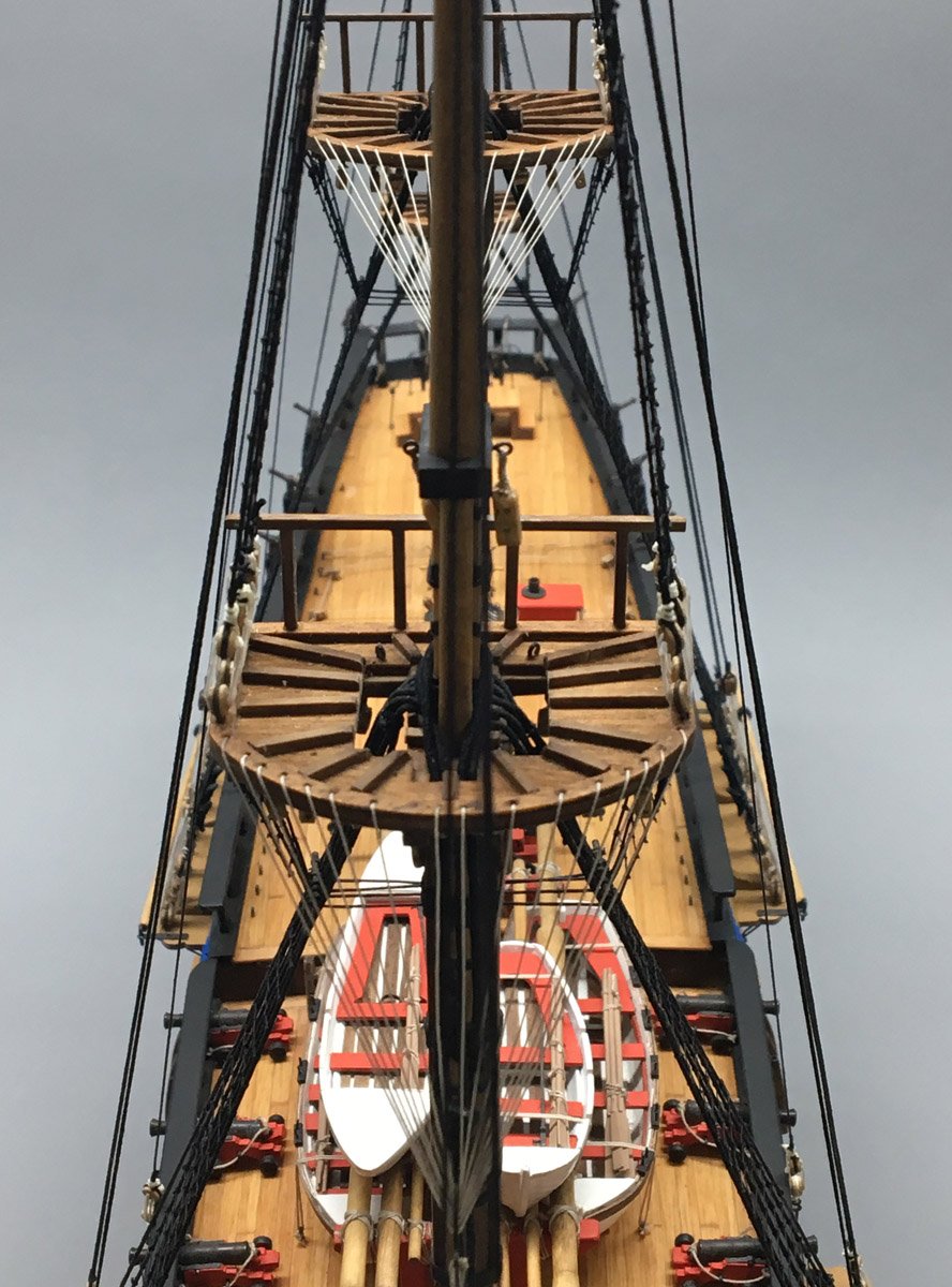
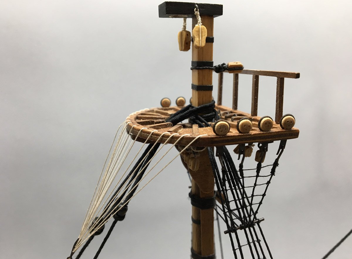
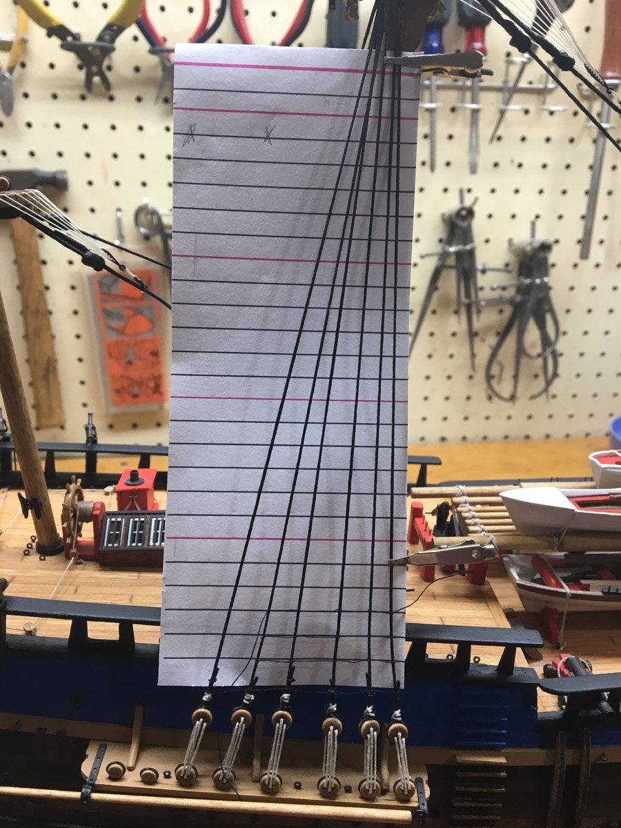
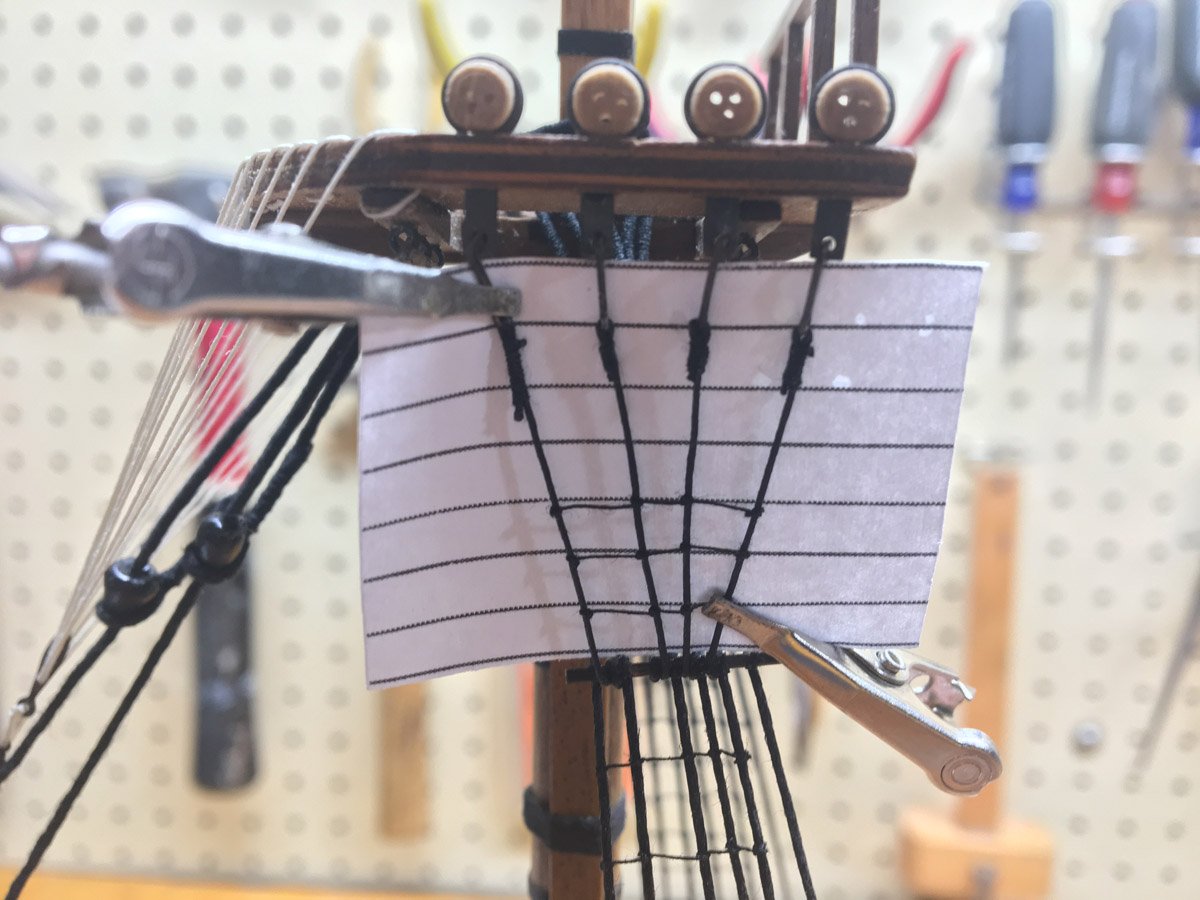
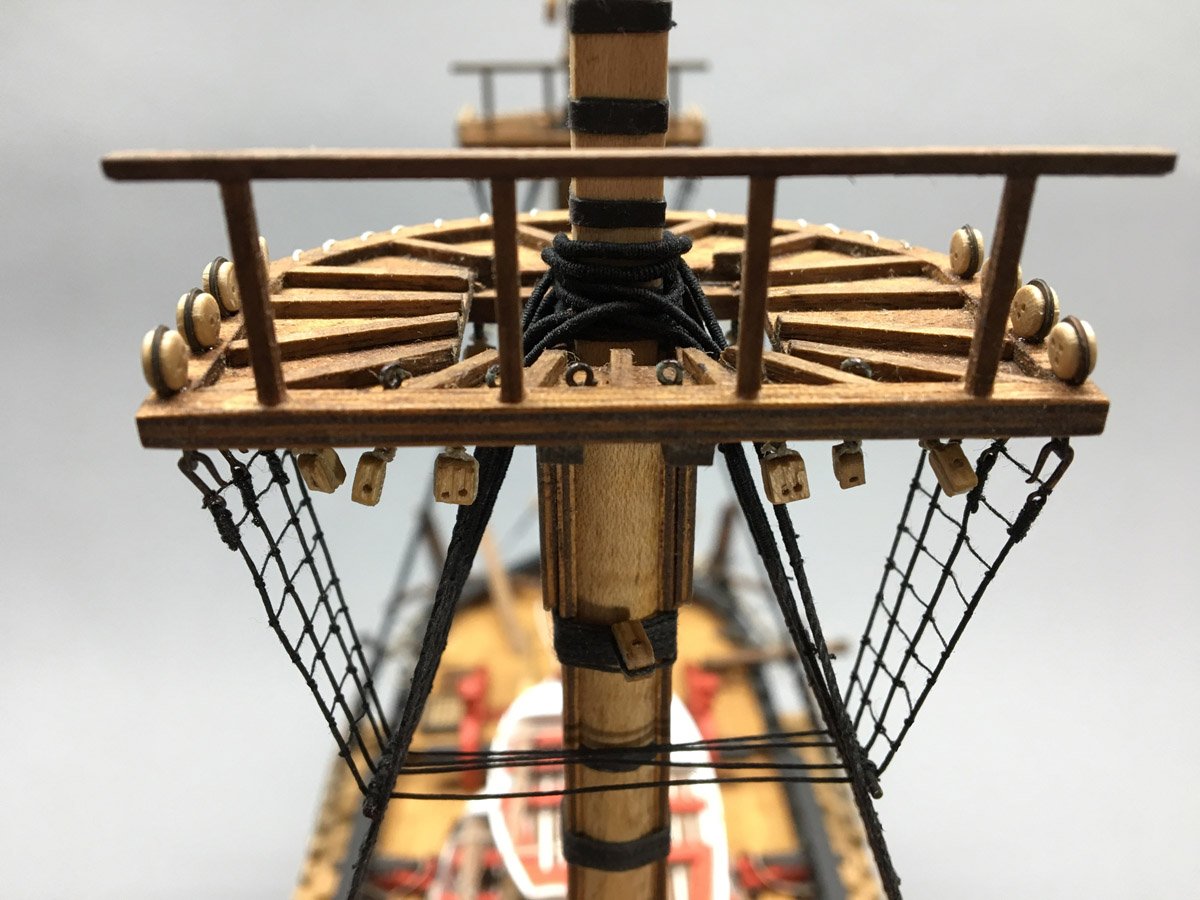
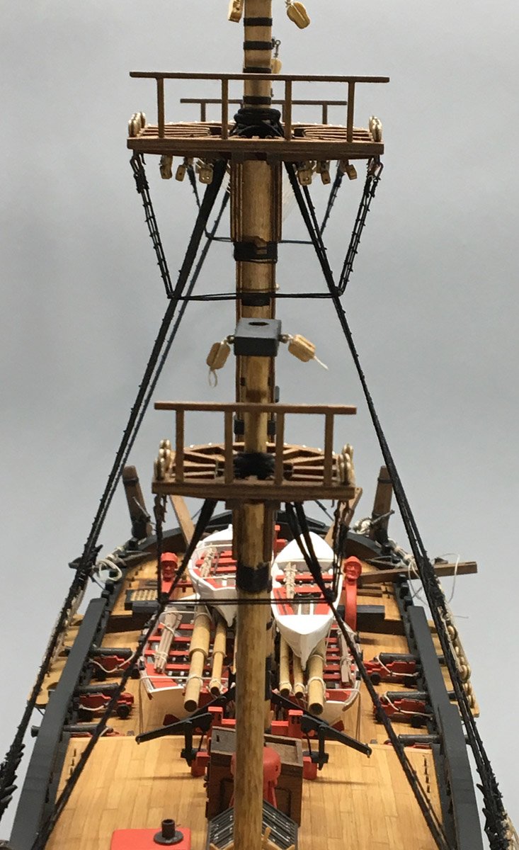
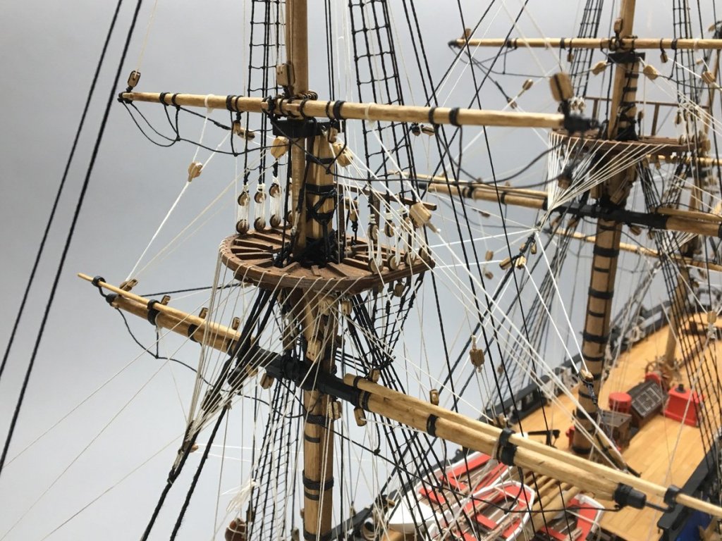
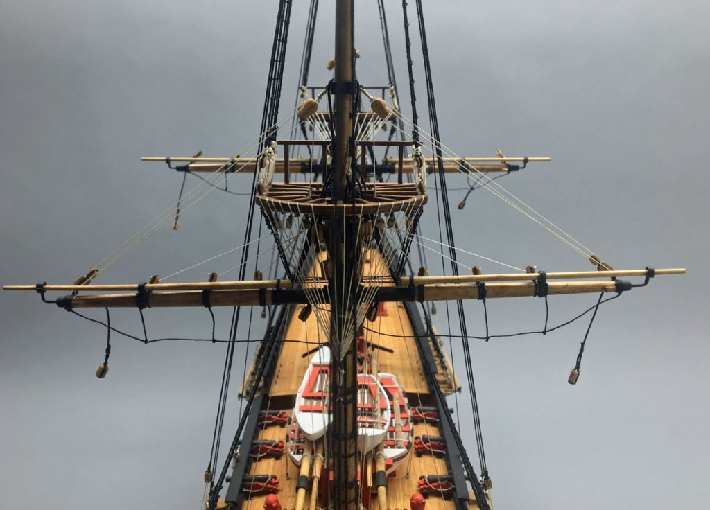
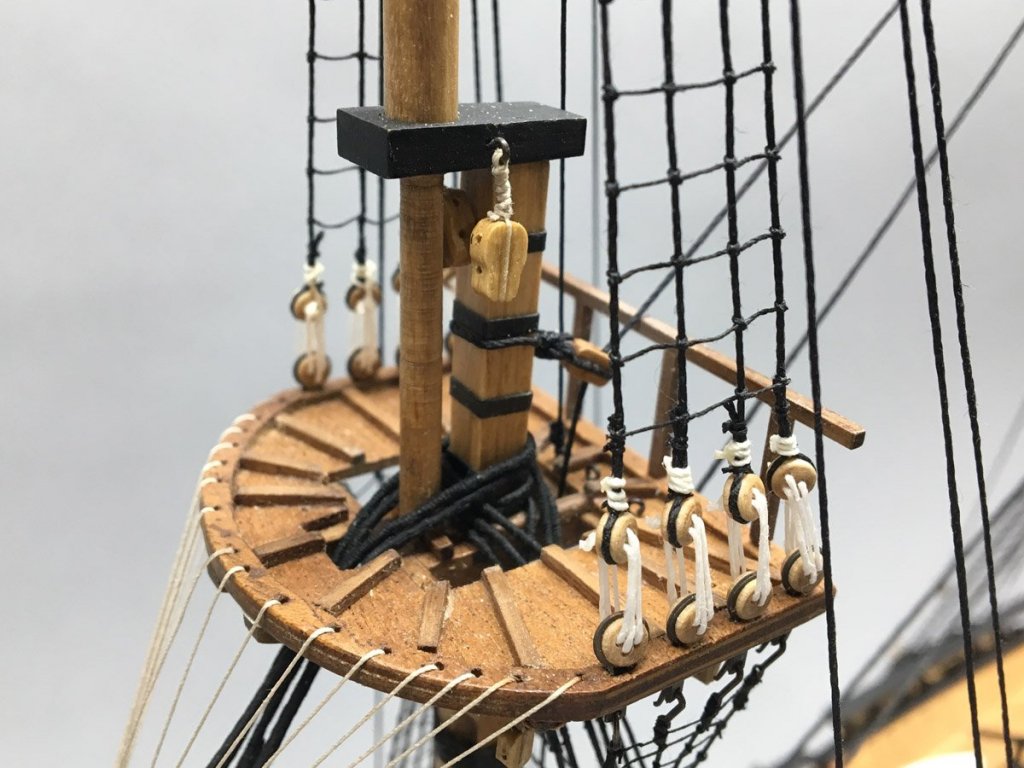
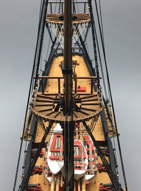
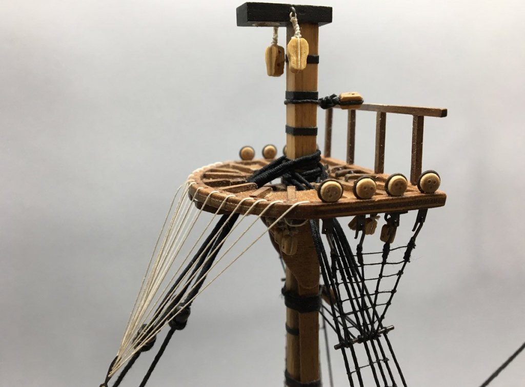
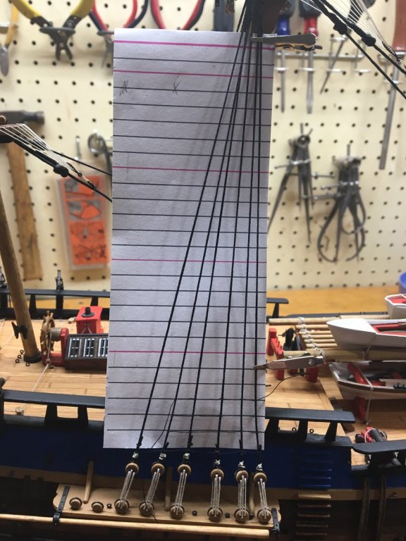
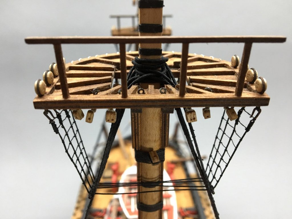
Ratlines I drew up a ratline spacing chart in Photoshop Elements, with 1/4" spacing corresponding to 16" spacing in full size. That's slightly big, with 12" - 14" being typical, but it looks OK to me. Here's the chart on the main mast. with the first couple of lines tied. I posted my method of tying ratlines way back when I built my Syren in 2013. Here's a link to the details if you're interested. Basically I used a clove hitch for the first knot, simple half hitches for the rest, and a spot of CA to hold everything together. I was slightly concerned about the half hitches slipping until I had to undo a crooked line. Once the CA is on the knots they do not want to move. It took me about 2 hours per set of shrouds to tie the ratlines, only about 12 hours total. The futtock shrouds and catharpins should comprise 3 separate lines: A port FS going from a hook on the top to a bar on the port shrouds A carthapin going from port shroud to stbd. shroud A stbd. FS opposite #1. I tried several ways to make separate lines but it was tough to get them all the right size to hold the tension. Something always ended up loose. Then I realized I could use a single line for everything. I seized a hook on one end, wraped it around to the other size, and temporarily attached a second hook. When all 4 lines were in place I adjusted the tension and seized the opposite hooks. Not historically accurate but very easy and looks fine. Here are a couple of image that shows the tops all rigged.


- 108 replies
-
- 3
-
-
- endeavour
- caldercraft
- (and 1 more)
-
Dashi, I'm happy to see you back. Your Endeavour was looking great, but you stopped updating your build log just after I started mine. Are you still working on the model?
- 108 replies
-
- 1
-
-
- endeavour
- caldercraft
- (and 1 more)