rvchima
-
Posts
712 -
Joined
-
Last visited
Content Type
Profiles
Forums
Gallery
Events
Everything posted by rvchima
-
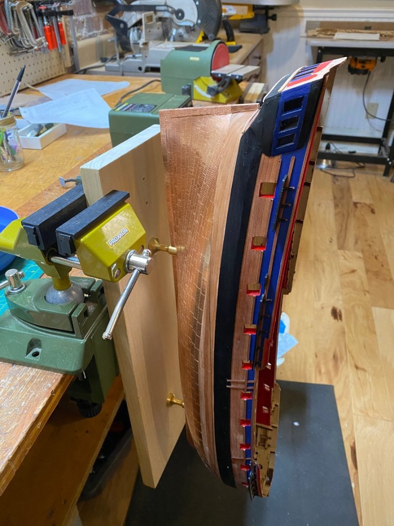
 Beautiful job on the planking. I also like your plan to leave the hull natural. It will look great. Do you have an electric plank bender for the stern? I bought one part way through mine and it worked amazingly well.
 -
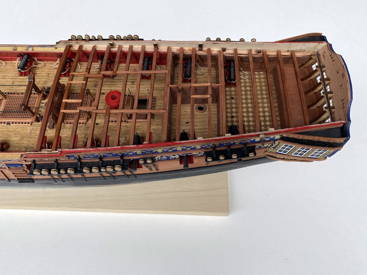
Quarterdeck Beams Installed - 308 Hours, 122 Days This was another satisfying task. I added the optional hanging knee braces below the beams, sanded most of the laser char, and finished all the pear wood with Watco oil stain. Yes, I know most of this won't be seen, but the pear wood is just so pretty that I can't resist.
- 96 replies
-
- 10
-

-

-
- Sphinx
- Vanguard Models
- (and 2 more)
-
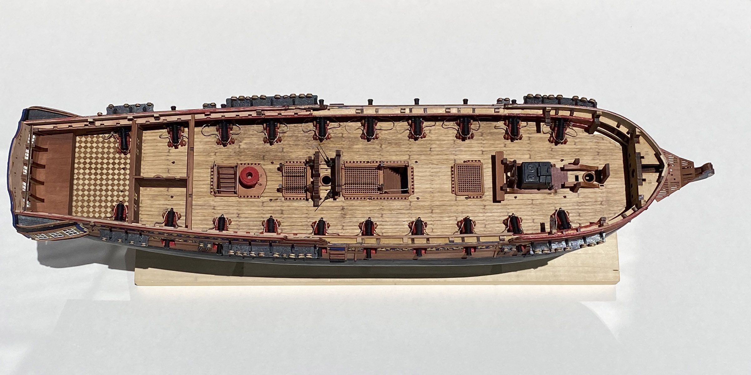
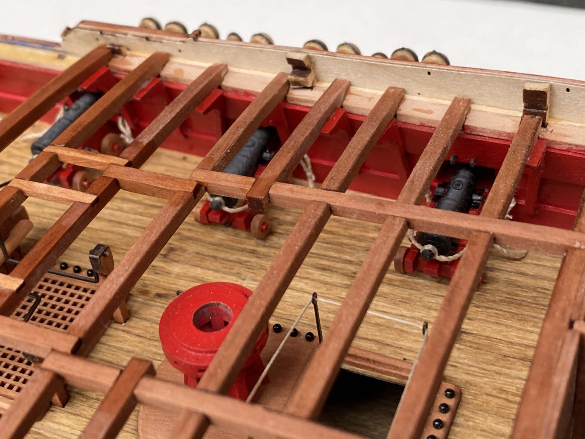
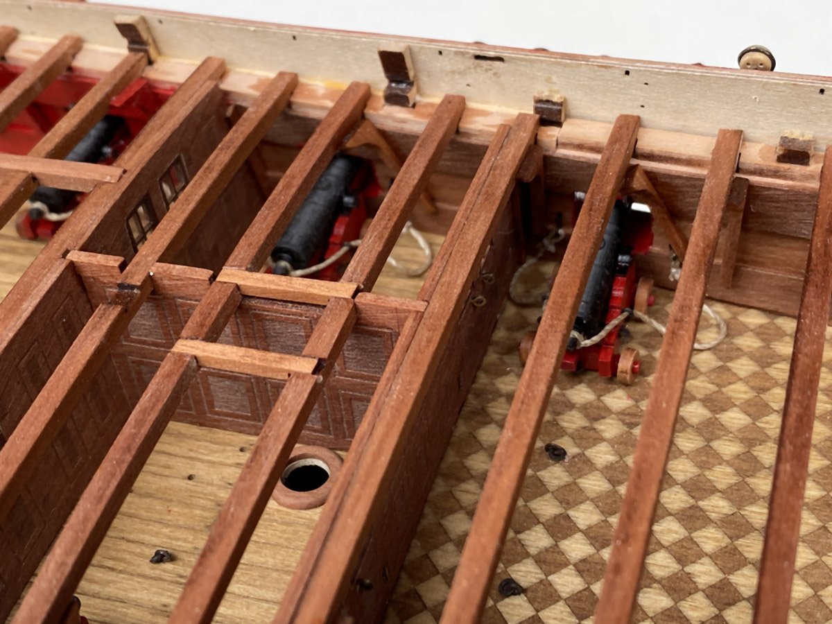
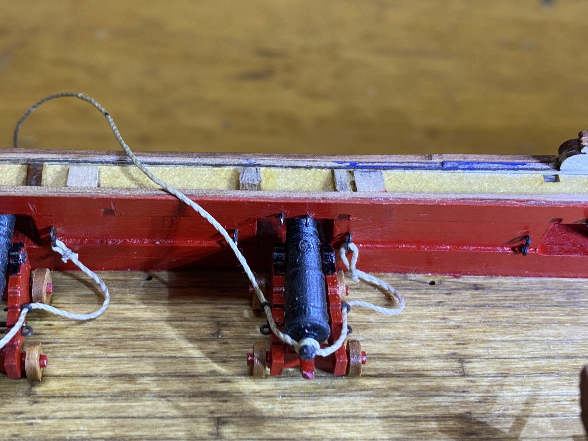
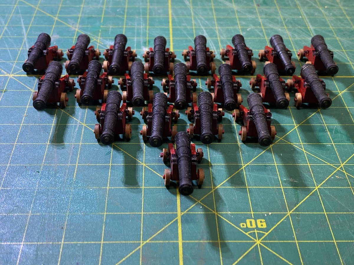
Cannons Installed with Breech Ropes This took another 12 hours over 3 days. About 27 hours to build and install 20 cannons. Now it's time to cover them all up with another deck.

- 96 replies
-
- 10
-
-
- Sphinx
- Vanguard Models
- (and 2 more)
-
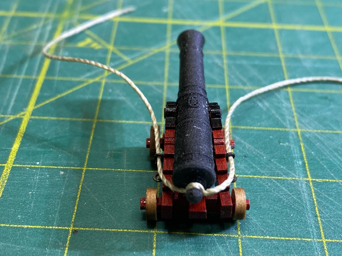
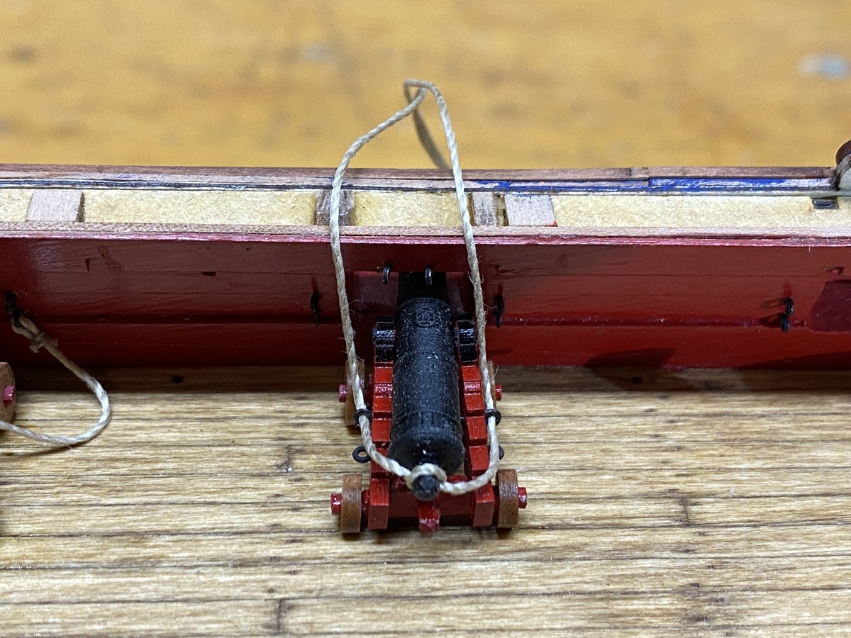
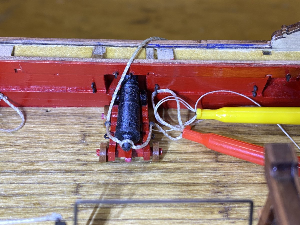
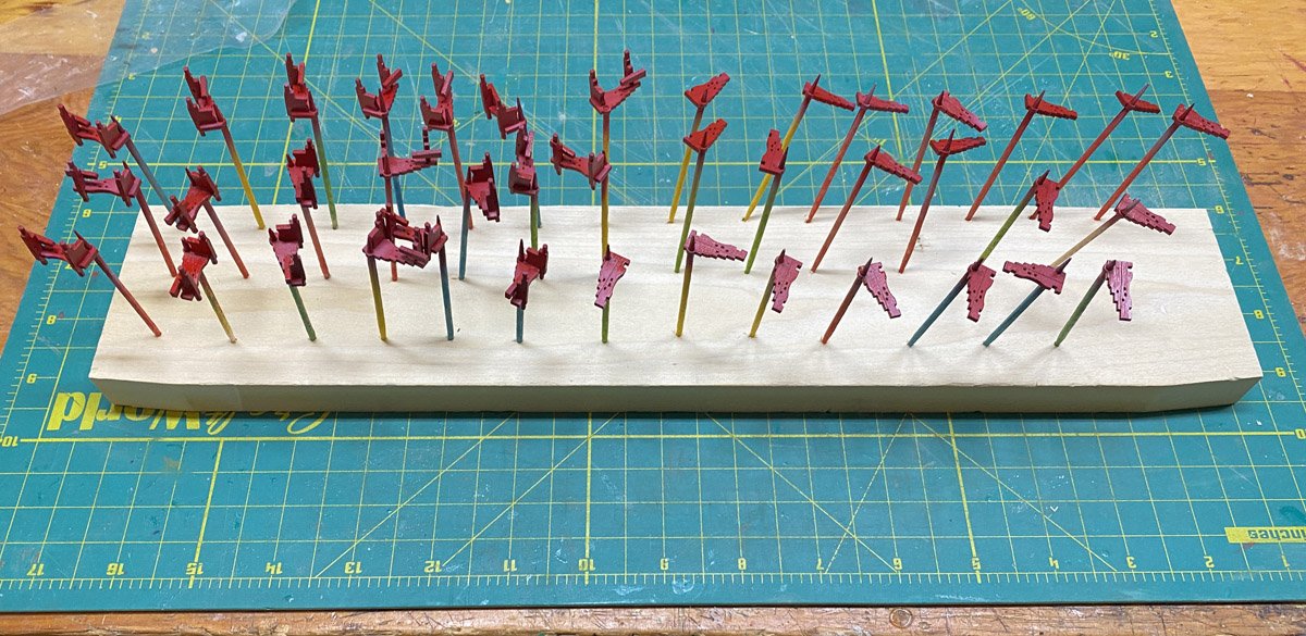
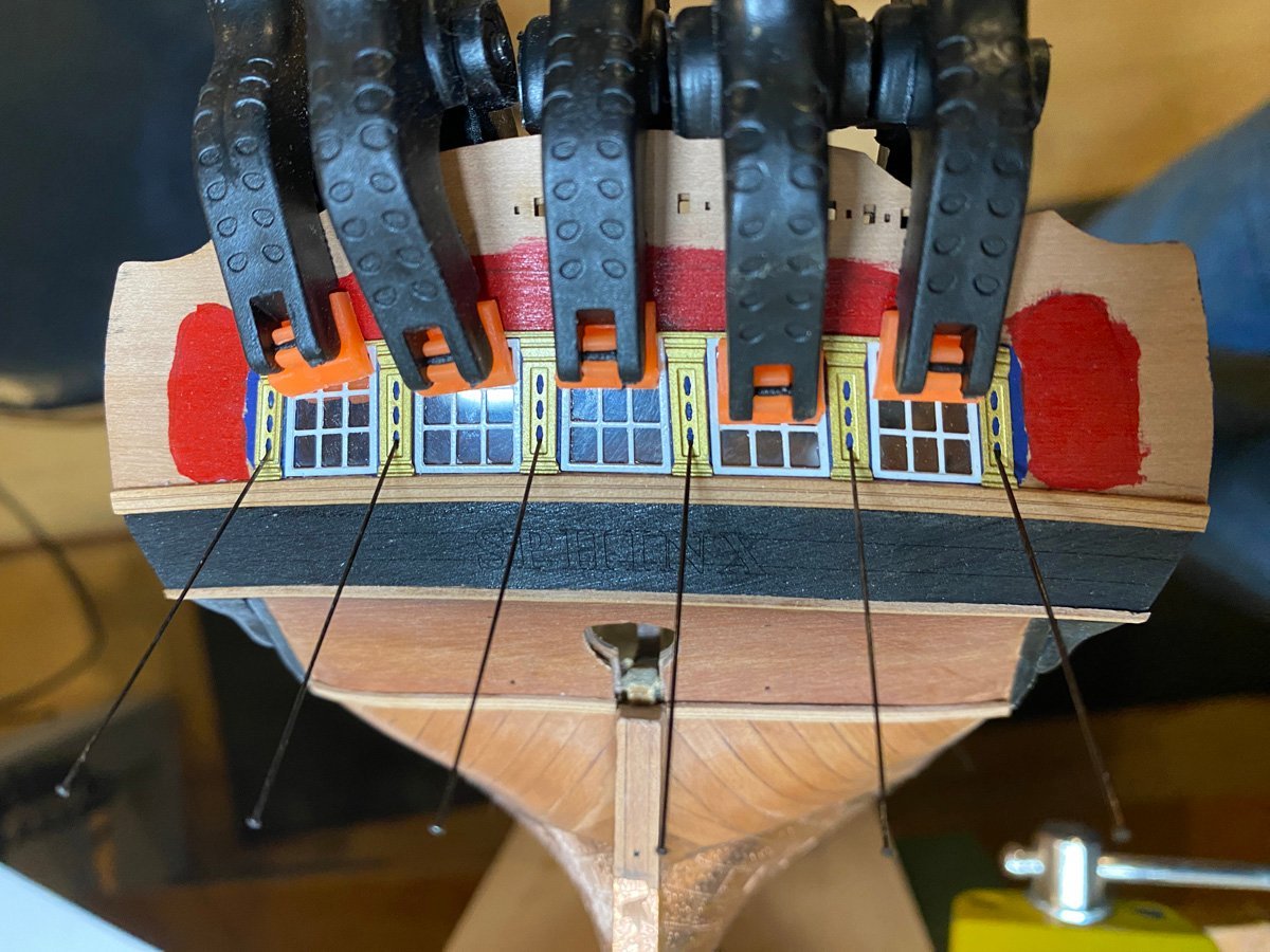
Breech Ropes As suggested, I am rigging the breech ropes to the cannons off the model. I just use a single knot under the barrel with a spot of CA. Then I glue the cannon to the deck. The ends of the breech ropes must go through the eyebolts and get tied with much thinner thread using a single clove hitch. It is quite difficult to tie a clove hitch in that tight space, but it is MUCH easier to tie a clove hitch in your hands by overlapping two simple loops. There is an excellent animation of the procedure here. I hold the clove hitch with an electronics test hook clip, then put the breech line through the clove hitch, through the eyebolt, and back through the clove hitch. I grab both ends of the breech line with another test clip (red.) So now I have a clove hitch around the breech line as desired. I release the yellow clip, snug up the clove hitch, add another single knot and a spot of CA for safety, release the red hook, and trim the ends. Fairly painless.

- 96 replies
-
- 9
-
-
- Sphinx
- Vanguard Models
- (and 2 more)
-
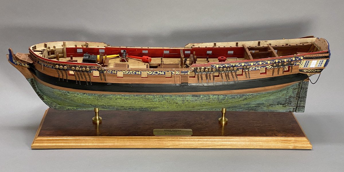
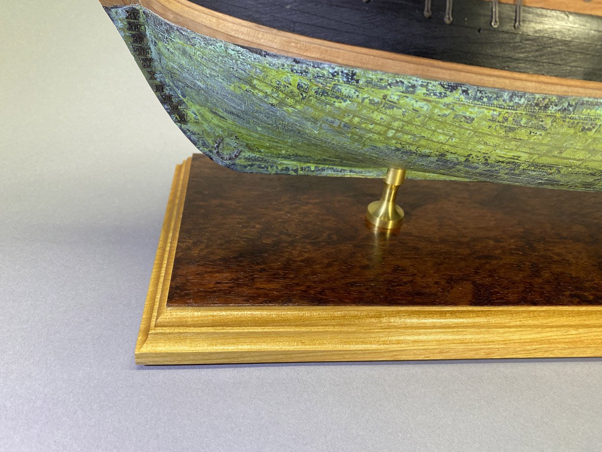
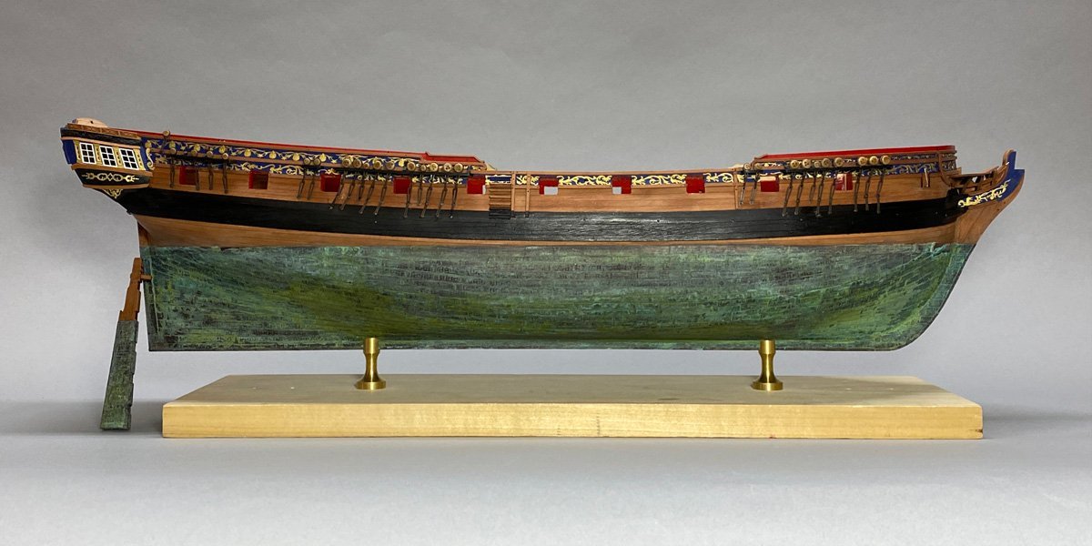
A New Base The outrageous patina on my copper hull needed an equally outrageous base. I made one out of a light cherry with a Bubinga veneer, finished with Watco natural oil and several coats of Minwax wipe-on polyurethane. I have been ordering brass name plates for all my models from a vendor on Amazon. The temporary base will go back on while I am working. I have just started to rig the breech ropes for the cannons. @Thukydides posted a brilliant description of a jig for rigging the cannons off the model here. However, the instructions for the Sphinx had me install the eyebolts around the gunports about 20 pages ago, so I will have to do that rigging in place.
- 96 replies
-
- 12
-
-
- Sphinx
- Vanguard Models
- (and 2 more)
-
Cannons Not as painful as I thought - it took about 15 hours to build 20 cannons.
- 96 replies
-
- 5
-
-
- Sphinx
- Vanguard Models
- (and 2 more)
-
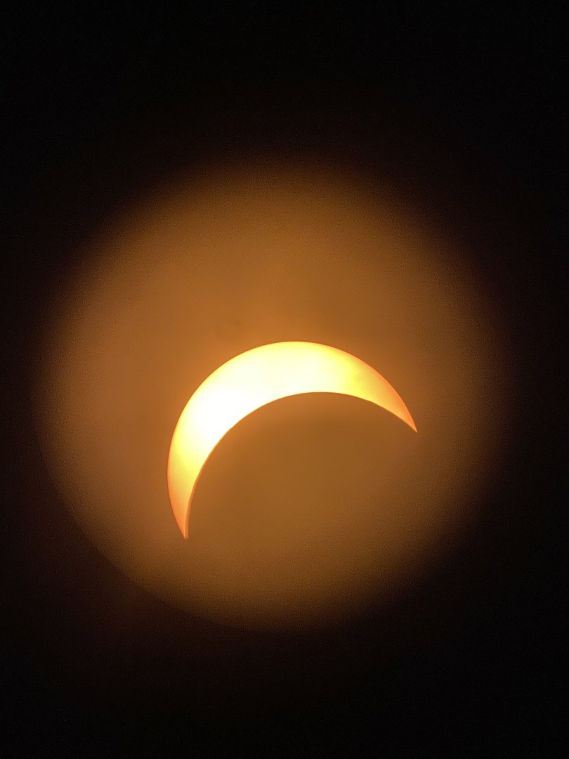
Eclipse We had a solar eclipse today, 87 percent coverage where I live but only briefly visible through the clouds. I managed to get one decent photo with my old Celestron 90mm spotting scope with a solar filter and an iPhone holder.
- 96 replies
-
- 5
-
-
- Sphinx
- Vanguard Models
- (and 2 more)
-
Cannons In my last post I wrote how much I was enjoying this build but I'm not looking forward to this next part. At least she's not a first rate.
- 96 replies
-
- 5
-
-
- Sphinx
- Vanguard Models
- (and 2 more)
-
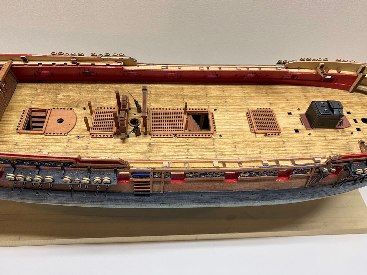
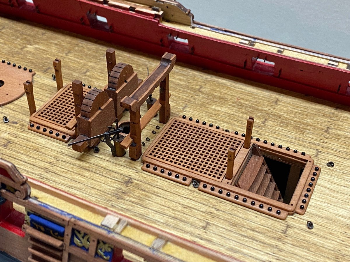
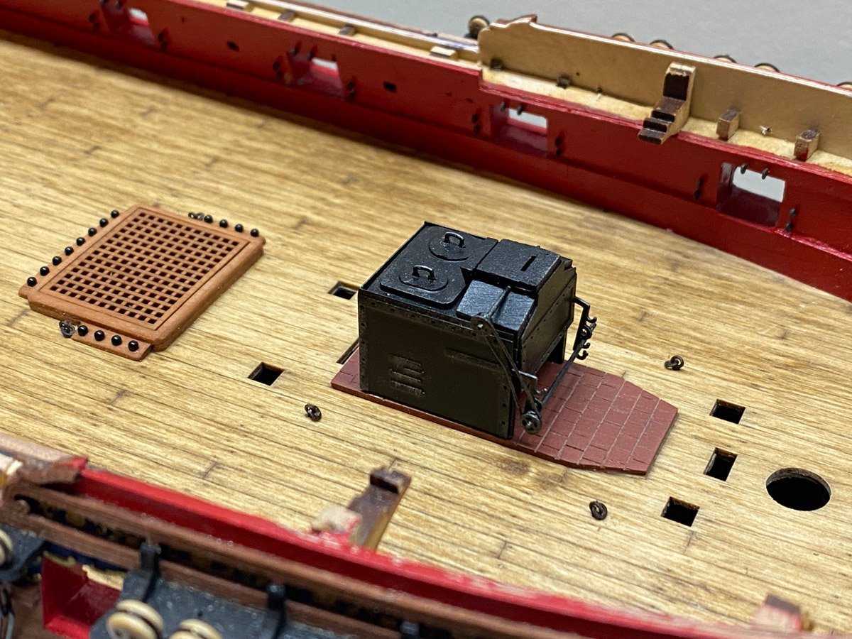
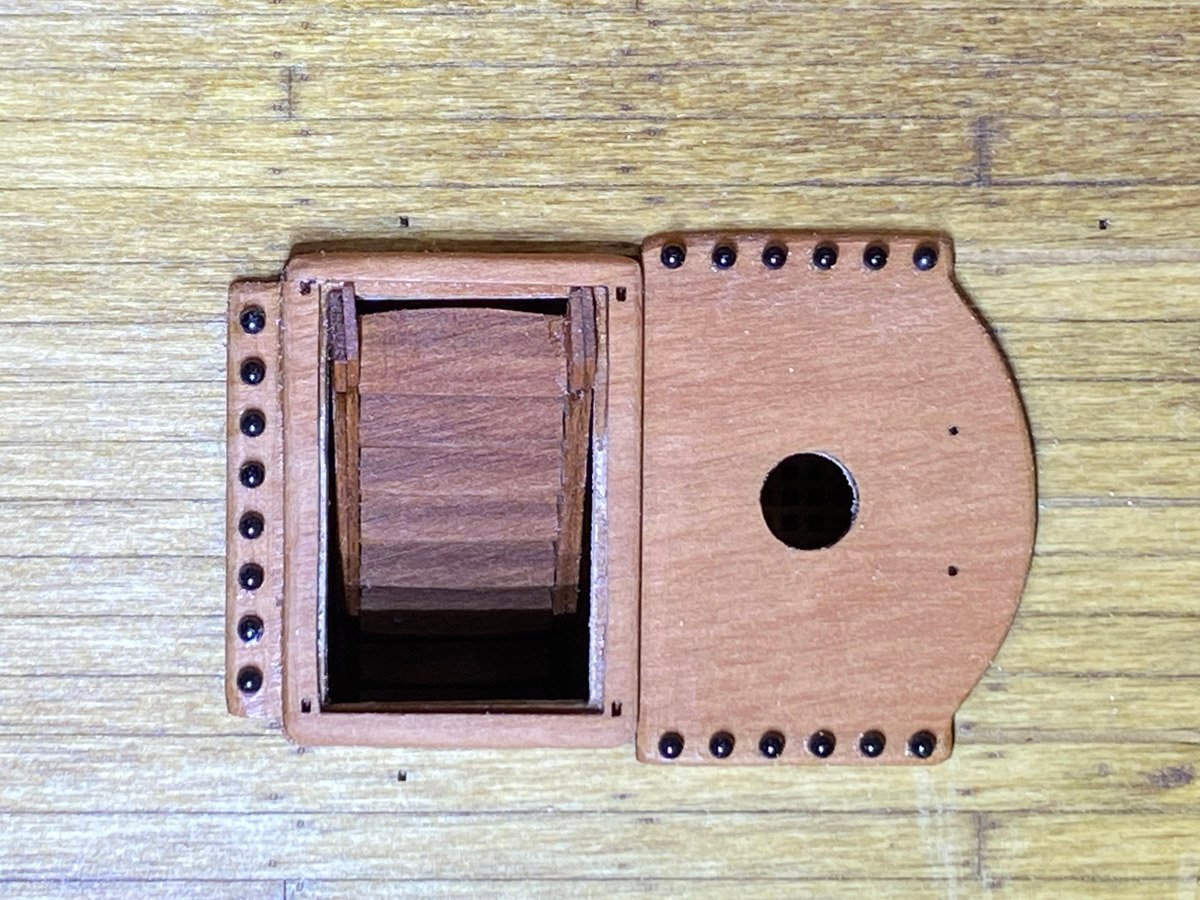
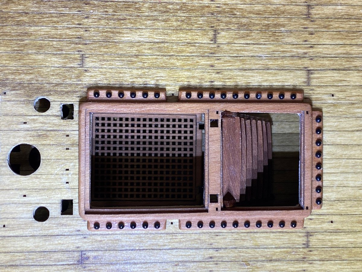
Chain Pumps, Hand Pumps, Grates and Finally the Stove This part of the build is quite enjoyable. Each little component adds something interesting to the model. I built the stove almost two months ago and finally got to install it, and to jump ahead three pages in the manual past those instructions.
- 96 replies
-
- 14
-
-
- Sphinx
- Vanguard Models
- (and 2 more)
-
Interview with Chris Watton in Nautical Research Journal If you haven't seen it already, there is a fascinating interview with @chris watton, designer of the Sphinx kit, in the latest issue of Nautical Research Journal. When I was looking for a new project I was debating between the Diana by Caldercraft and the HMS Fly by Amati. Moderator @ccoyle told me that I had a good eye because both models were designed by Chris Watton, and suggested that I consider the Sphinx. After reading the article I realize that I could have chosen any number of kits and that Chris would probably have designed most of them. The only thing missing from the article is a photo of Chris' private collection. My house is getting crowded. Chris' house must be a museum.
- 96 replies
-
- 3
-
-
- Sphinx
- Vanguard Models
- (and 2 more)
-
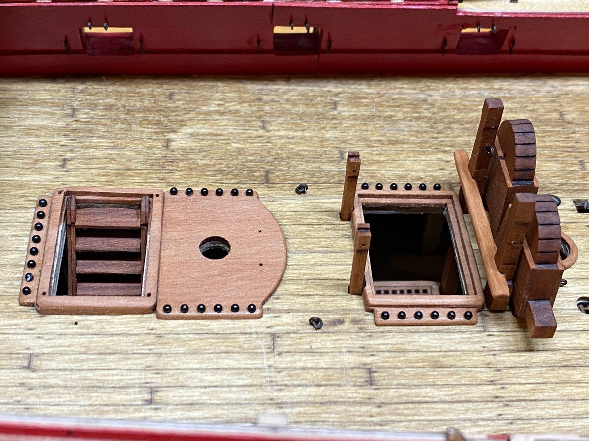
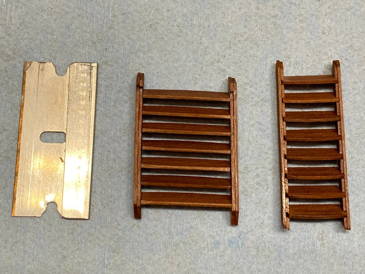
Thank you Thukydides. The patina is more intense than I ever imagined but I like it. I was hoping for a visually striking model (even if not quite historically accurate) and it is certainly turning out that way. By the way, do you have another name besides Thukydides? Two Ladders - Never to Be Seen Again Chain Pumps and Supports
- 96 replies
-
- 10
-
-
- Sphinx
- Vanguard Models
- (and 2 more)
-
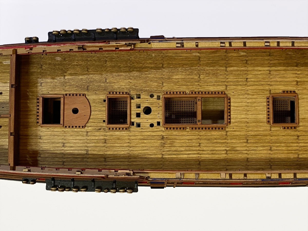
4 Hatch Coamings and 88 Cannon Balls I figured it would be easier to place the cannon balls before the coamings were installed.
- 96 replies
-
- 11
-
-
- Sphinx
- Vanguard Models
- (and 2 more)
-
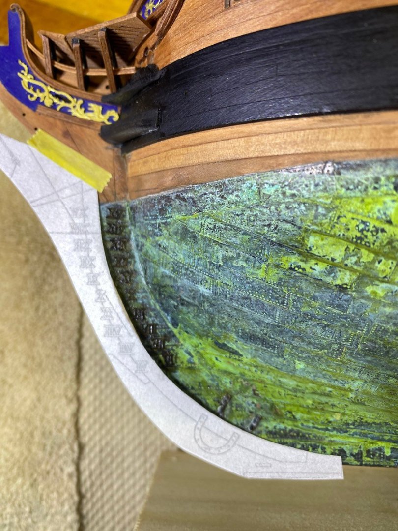
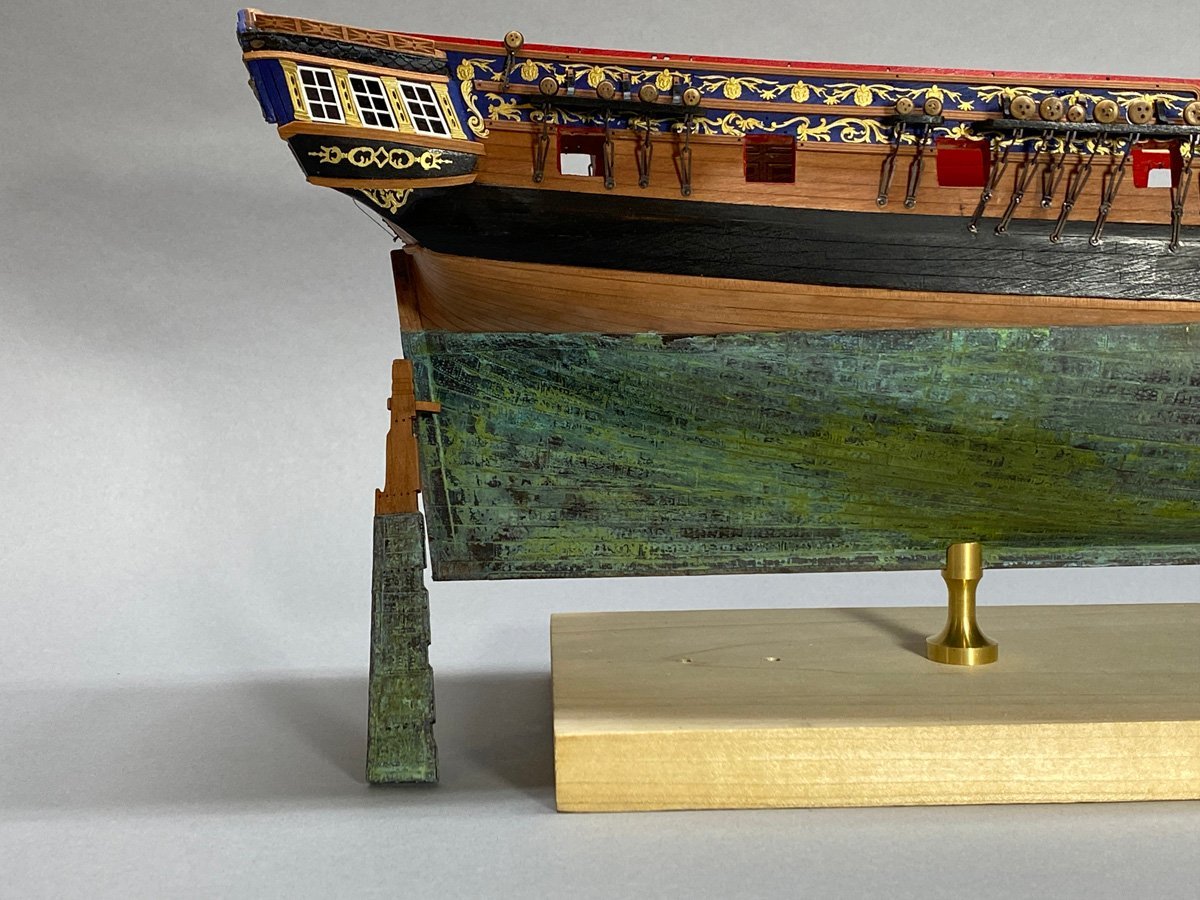
Outside of the Hull (Finally) Complete The rudder, displacement numerals, and random reinforcing plates are now attached. The rudder was hard because of about 120 nails holding the gudgeons and pintles. Those parts are non-functional - the rudder is actually held in place by 5 PE pins. A while ago I mentioned that my rudder wouldn't fit past the rudder post so I removed 1/4" at the top. Now the top pin has nowhere to attach. And with the pins the rudder was now a few mm wider and wouldn't tip in place. I had to use my trusty rotary tool to enlarge the hole in the hull, which is what I should have done in the first place. I glued the displacement numerals with CA. The plans showed the starboard side so I did that first using a cutout copy of the plans for placement. For the port side I made a mirror image of the pattern with Photoshop and started gluing. After a while I realized that Roman numerals look the same forwards and backwards, but XI is not the same as IX. So I had to remove and reverse a few numerals. That removed the patina, which turns out to be fairly delicate. I touched it up with random green and black acrylic. When I attached the copper plates I covered up the holes for the horseshoe and keel plates. I laid the paper cutouts in place, poked a pin through a marked hole, and hit the corresponding hole through the copper on the first try. Amazing!

- 96 replies
-
- 11
-
-
- Sphinx
- Vanguard Models
- (and 2 more)
-
Thanks everyone! Now I know how NASA faked the Magellan radar map of the surface of Venus. Ha ha, only joking. I'm retired from NASA and we never fake anything.

- 96 replies
-
- 5
-
-

-
- Sphinx
- Vanguard Models
- (and 2 more)
-
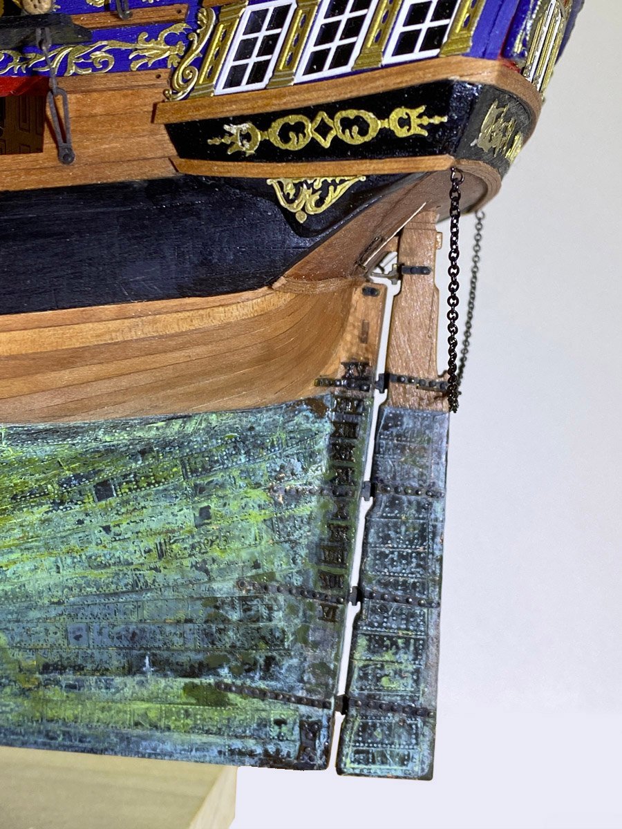
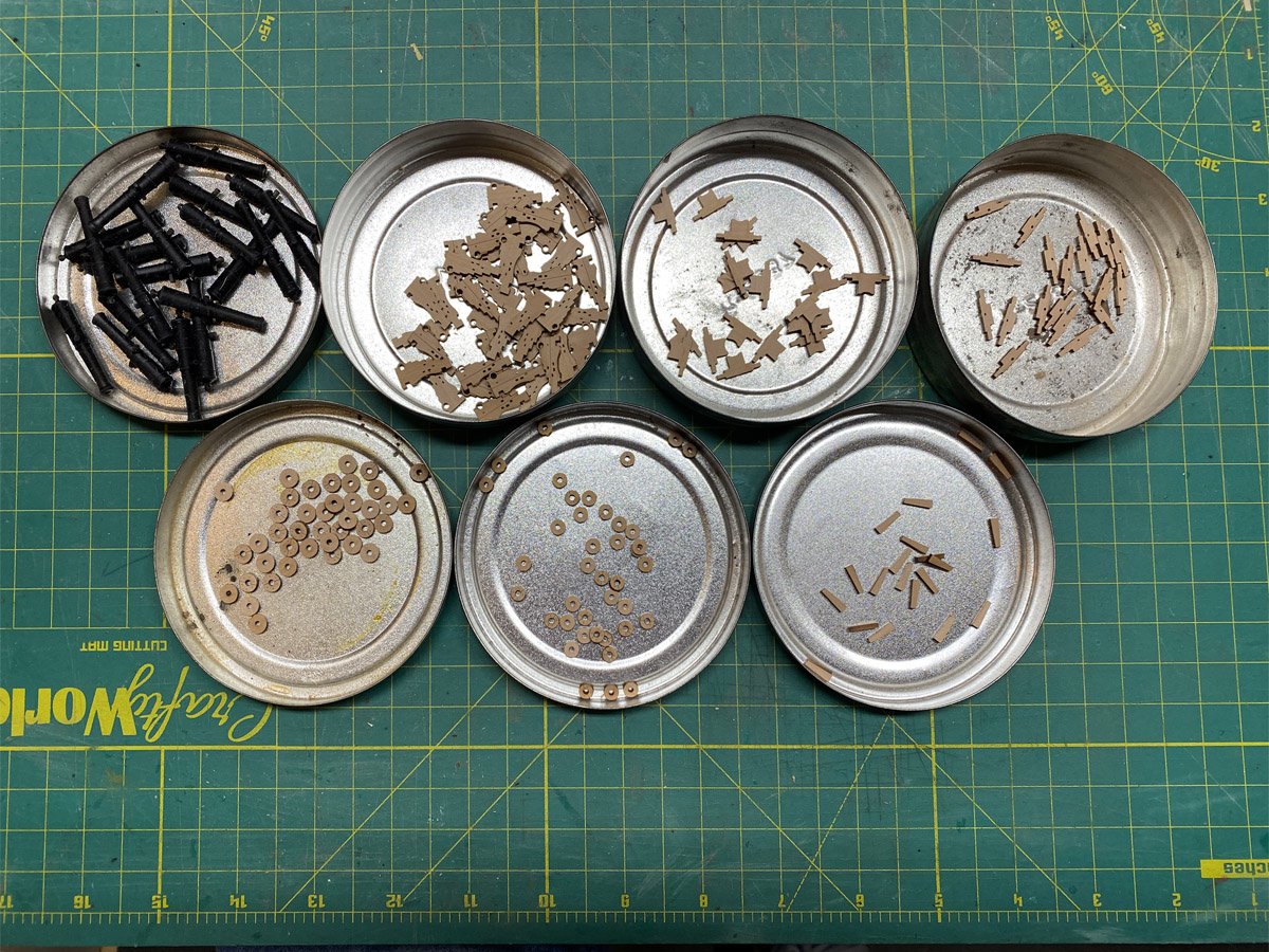
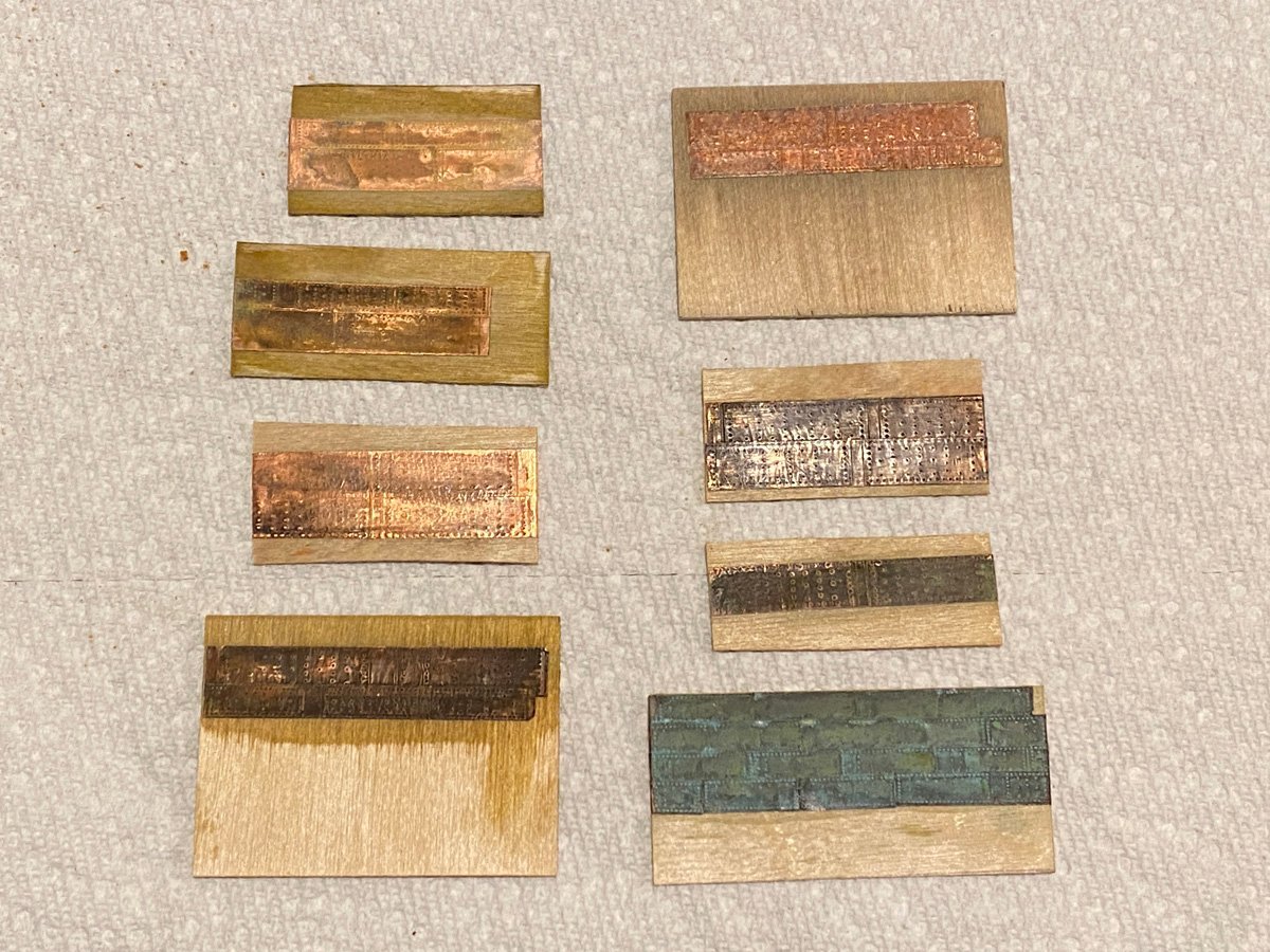
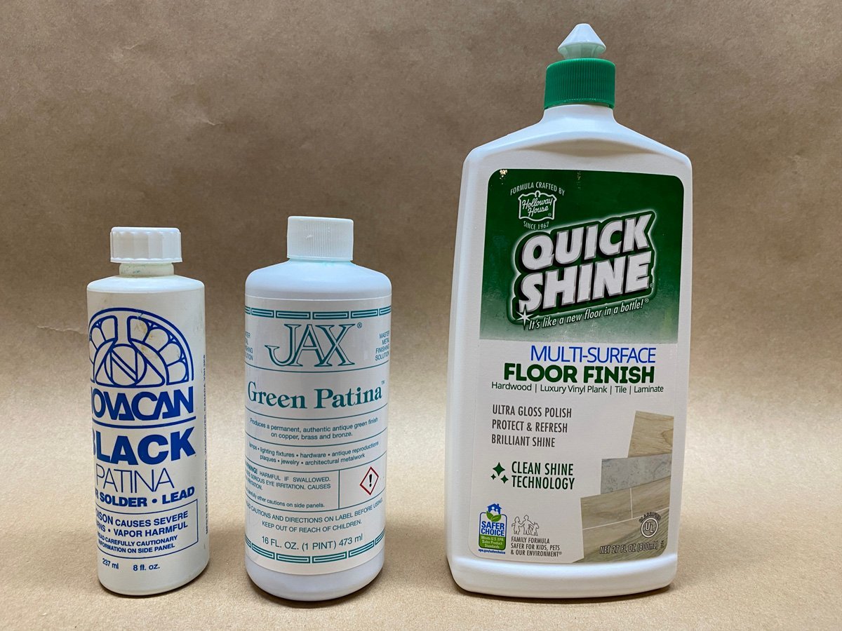
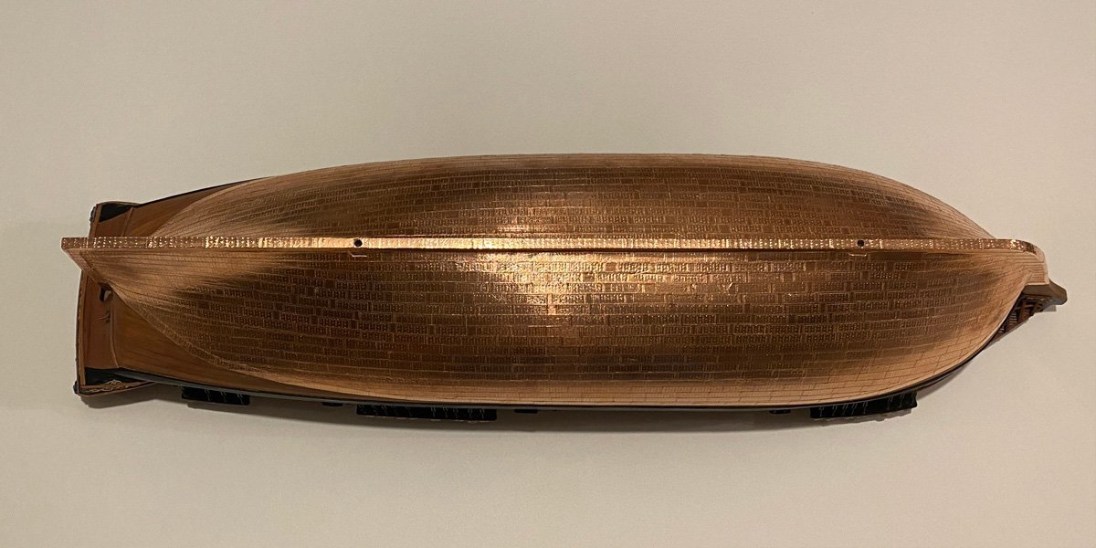
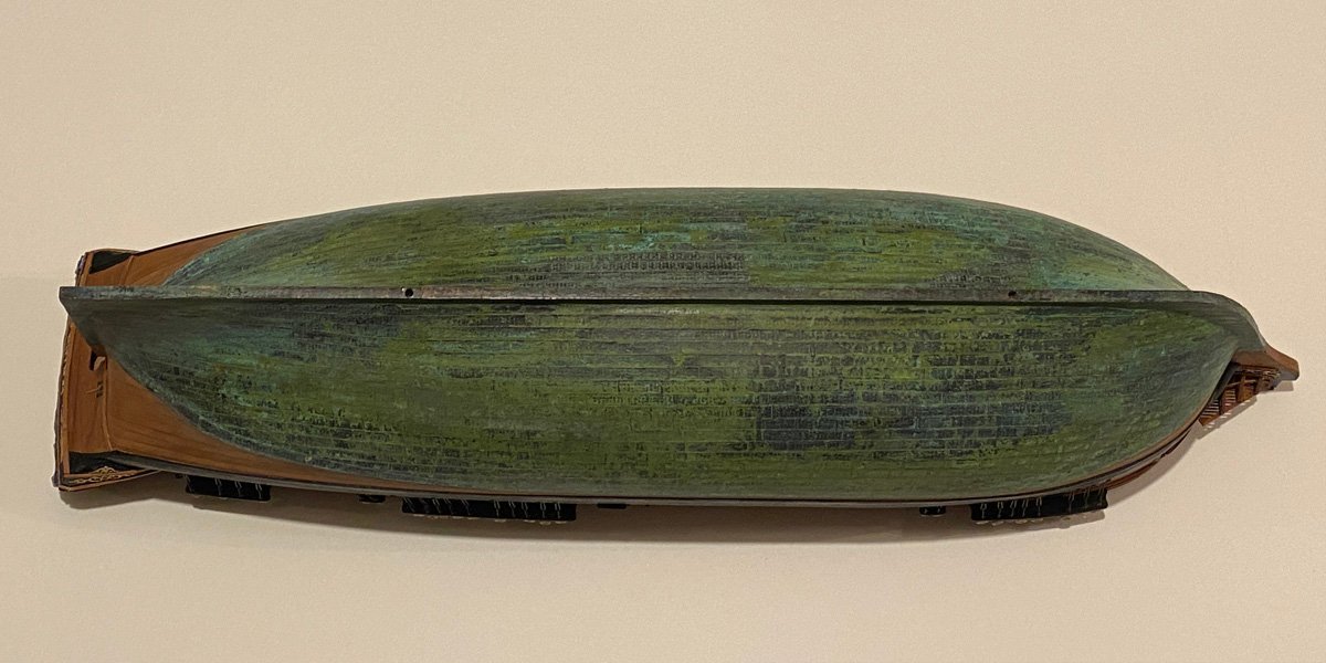
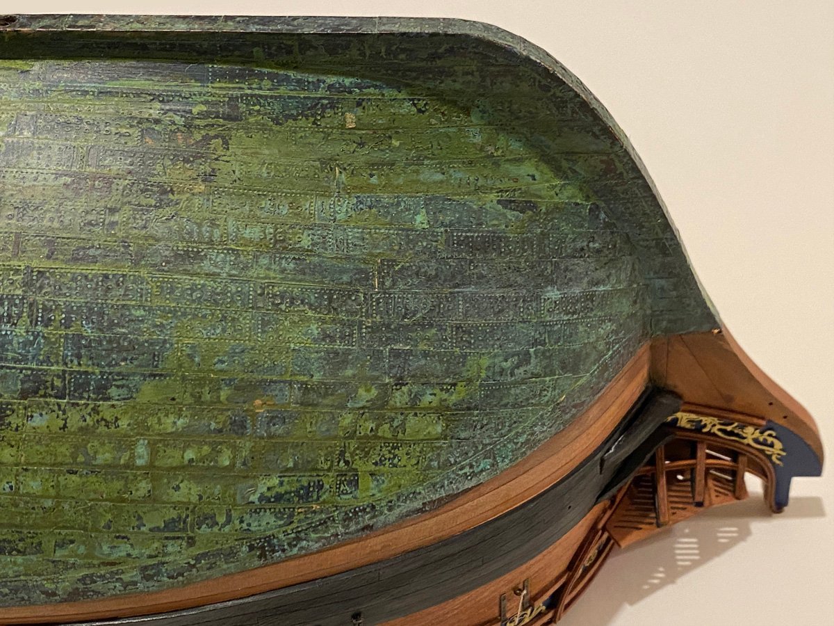
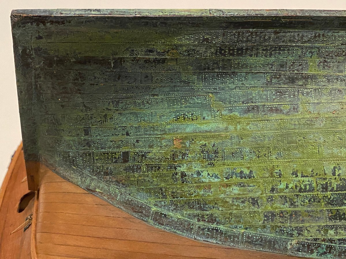
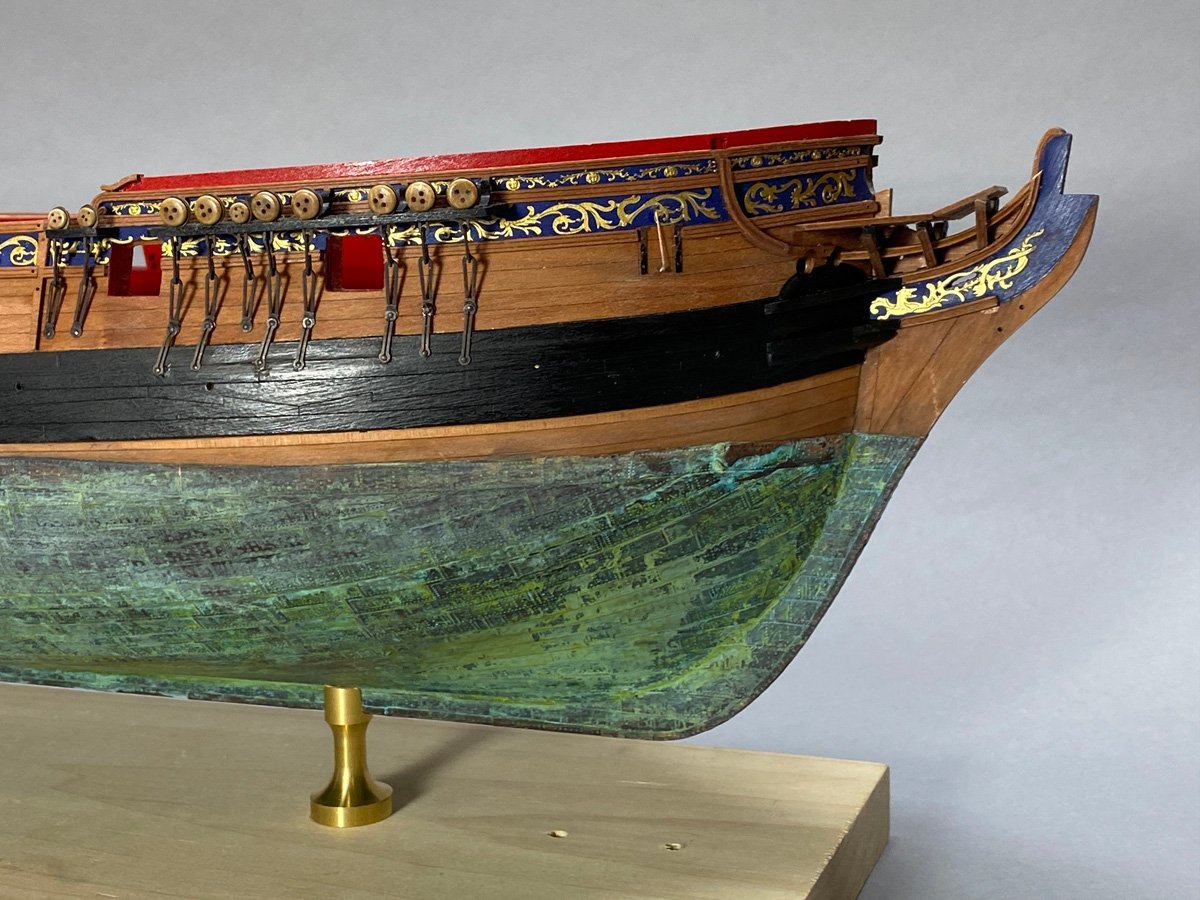
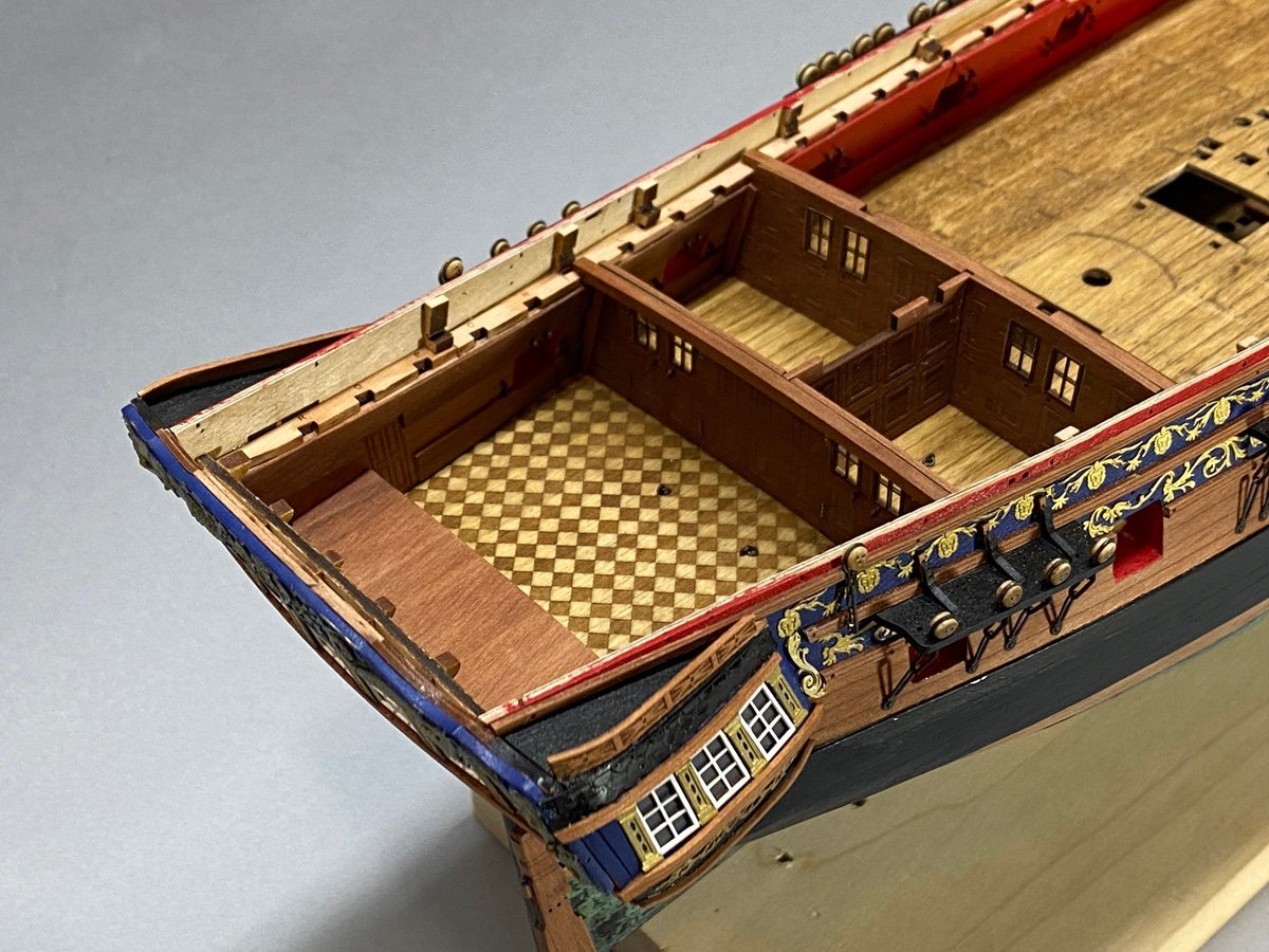
Now the Copper is Green! I experimented with high-test vinegar and ammonia, salt and Miracle grow, cleaning the foil with alcohol and, lacquer thinner. (I did not try peeing on my ship.) Nothing had much of an effect until I tried the Novacan black patina that I use for stained glass and to darken the photo etched parts. It made the foil look like a tarnished penny, dark brown, almost black. I wanted green so I took a chance on a large bottle of Jax Green patina from Amazon. It didn't do much by itself and it tended to rub off. But over top of the Novacan black - wow! The patina seemed durable but I air-brushed several coats of acrylic floor wax over it just in case. Here is a photo of all the samples I tried. No point in identifying the losers, but the Novacan + Jax + acrylic is at bottom right. Here's a shot of the chemicals. Novacan black starts to darken immediately and unevenly, but I brushed it continuously with a stiff 1" paint brush until it evened out (15-20 minutes per side.) I rinsed the hull with a sponge and water. Jax green patina paints on like water, one wet coat, and turns green as it dries. I let it dry overnight. Halloway Quick Shine is an acrylic floor wax that plastic modelers use for a clear coat. I masked above the water line and applied three light coats with an a air brush. I doubt if I used more than 1/2 ounce of anything. Before After There were gaps between the stamped plates on the copper tape that I neglected to remove towards the bottom of the hull. They are pretty well camouflaged now. The green patina is not at all what I was planning on - it's even better. I built the cabin walls while I was waiting for chemistry experiments to react. Now to attach the rudder.
- 96 replies
-
- 16
-
-
-
- Sphinx
- Vanguard Models
- (and 2 more)
-
My Copper Won't Turn Green! I finished coppering the hull and rudder, and was ready to age it. In 2013 I used kitchen vinegar and salt on my Syren and it looks great. Today I made up some samples of my copper foil on wood to experiment with. I tried 6% acetic acid kitchen vinegar with salt 20% weed killer vinegar with salt 20% vinegar with Miracle Grow ammonia with salt ammonia with Miracle Grow lightly sanding or rubbing the foil with steel wool first Nothing had any effect at all on my samples. They are just as shiny as before, and I am stumped! Does anyone have other suggestions for ageing the copper foil? I just discovered that Novacan Black Patina for Solder blackens the foil almost immediately. That's not the aged green that I was looking for but it's a start.
- 96 replies
-
- 2
-
-
- Sphinx
- Vanguard Models
- (and 2 more)
-
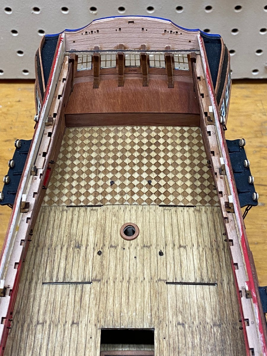
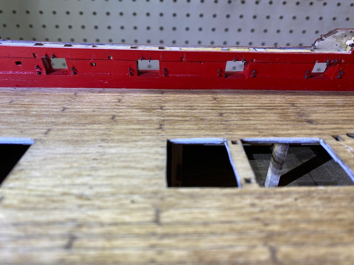
Chains are Done, on to the Interior - Temporarily One of the first tasks on the interior is to place 6 eye bolts around each gun port, 120 in all. As Walter says, My curved hemostat was perfect for inserting the tiny eye bolts. Four more bolts with tiny rings go in the floor, and a wooden ring surrounds the mizzen mast. I was getting excited about working on the cabins, but today my extra copper foil finally arrived from China. So back to the hull and rudder.

- 96 replies
-
- 8
-
-
- Sphinx
- Vanguard Models
- (and 2 more)
-
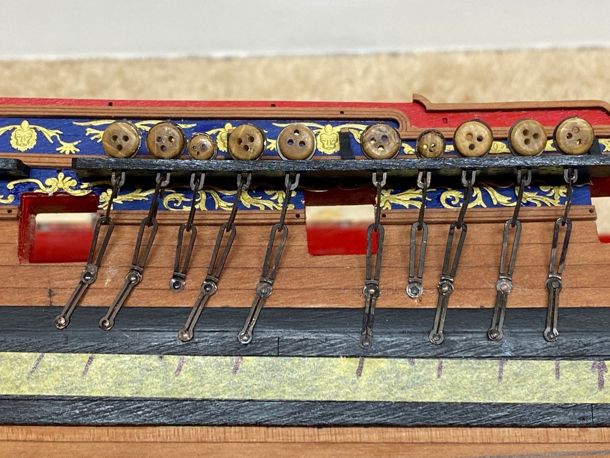
26 Chains for the Port Side Some assembly required.

- 96 replies
-
- 7
-
-
- Sphinx
- Vanguard Models
- (and 2 more)
-
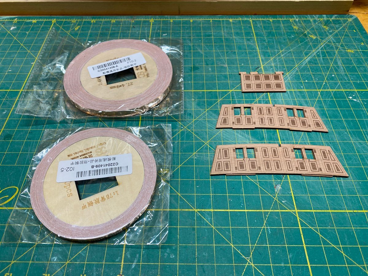
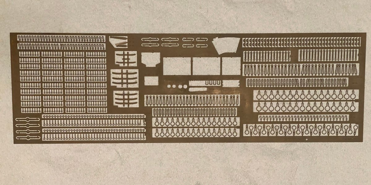
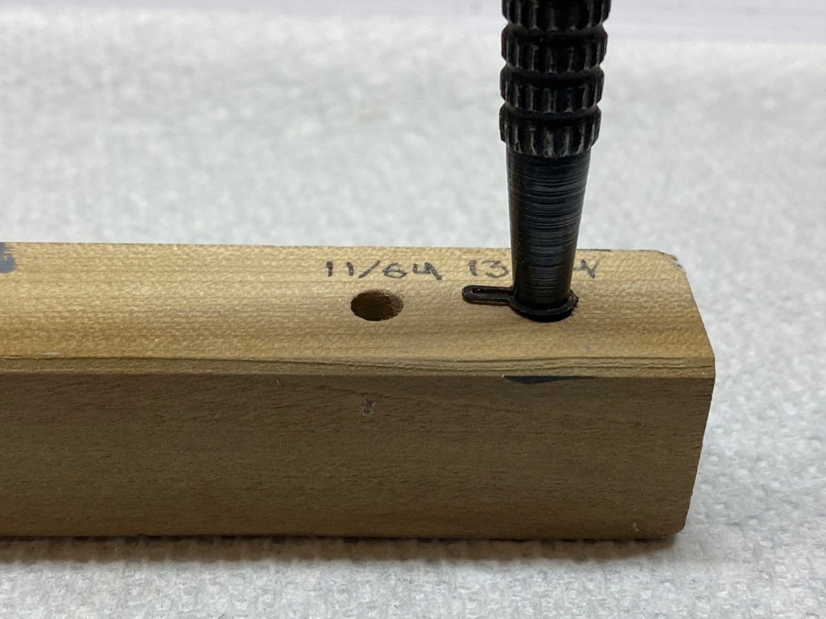
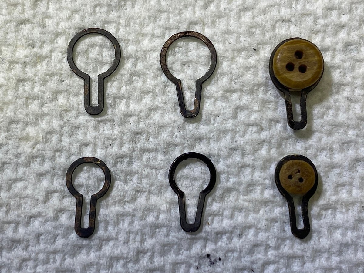
Chain Gang The chains comprise a zillion PE parts that have to be darkened somehow. The manual suggests paint but I blackened the entire sheet using Novacan Black Patina for Solder. One of my other hobbies is stained glass and I use this product to darken the solder. I set the PE sheet in a plastic tray, brushed on a little patina liquid, rinsed, patted dry, and sprayed with Lemon Pledge. The blakening can rub off here and there, but not back to shiny brass so it leaves a rustic appearance. The bit where the parts attached to the sheet can be touched up with a black marker. The rings for the deadeyes must be expanded quite a bit for the deadeyes to fit. I butchered a few trying to open them with pliers, but found another way. I drilled holes in a scrap of wood slightly larger than the ID of the rings. 13/64" works well for the large deadeyes, 11/64" for the small. I placed the ring over the hole, and used a center punch to open the ring symmetrically. One tap with a small hammer and the deadeyes open right up. Drop the deadeye in, then use needle nosed pliers to tighten the rings back up. UPDATE - I've found that I don't need the drilled wood at all. I can push the rings over the center punch by hand easily. 10 chains done, 42 more or less to go.
- 96 replies
-
- 10
-
-
- Sphinx
- Vanguard Models
- (and 2 more)
-
Walter, How did you spread the rings that go around the deadeyes? I am having trouble inserting the deadeyes without damaging the finish. Rod
-
The gunport linings look great, and your use of clothes pins as wedges is brilliant!
-
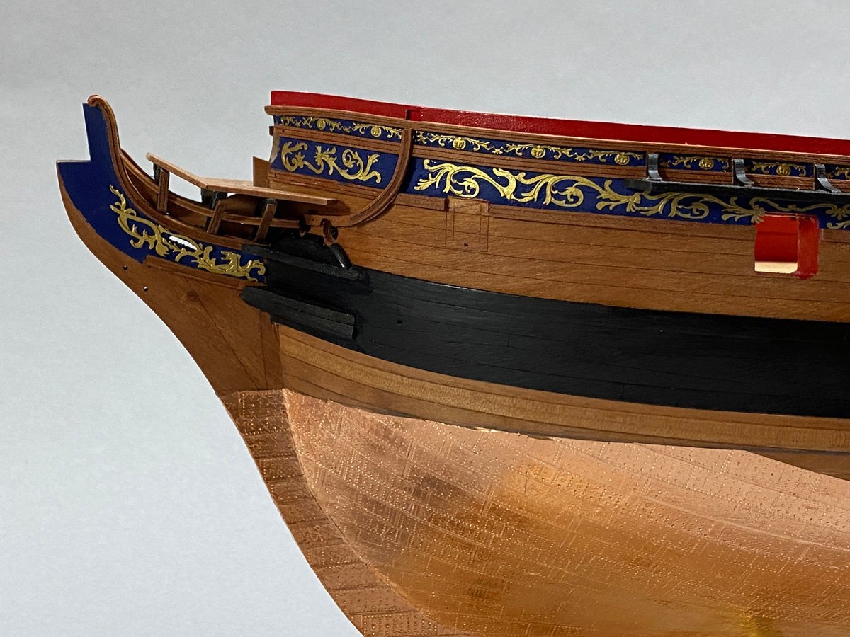
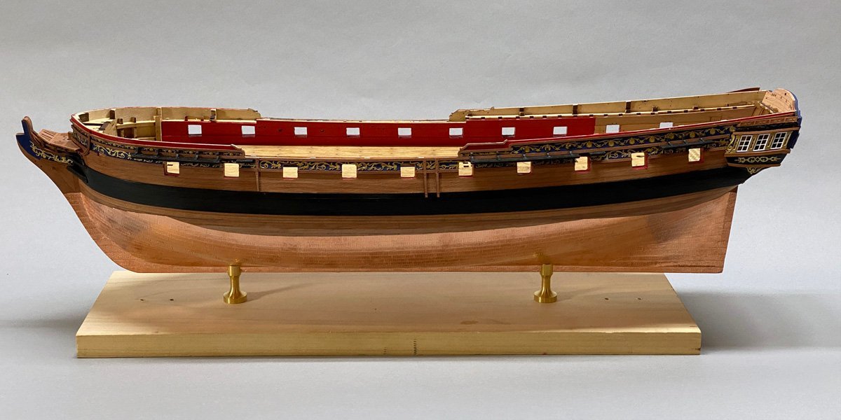
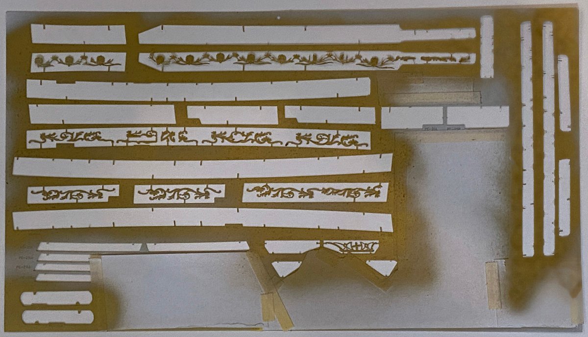
External Filigree Complete, 189 Hours, 87 days All the external photo-etched filigree took up most of a sheet of PE, so I masked off what wasn't supposed to be gold and painted the rest in place. That was the only way to keep track of everything. Sorry about the blurry image. The manual recommends attaching the parts with Pledge Future acrylic floor wax. Paint the area first, let it dry, put the filigree in place, then run more polish underneath to hold the part in place. Future is no longer available but the plastic modeling sites recommend Holloway Quick Shine. I got some and tried it on the first piece. It worked, but it was hard to hold the piece in place and the polish left shiny brush marks everywhere. So that didn't work well for me. Does anyone want a quart of floor polish? I ended up cutting the filigree into manageable sections, holding each piece with my double-sided tape sticks (see previous post,) and using a glue looper to wet the back with thin CA. Then I held the piece in place for a few seconds and it was done. In a few places on the starboard side my gun ports were too close to the upper rails and I had to omit some filigree. It took about 10 hours to do all the filigree.
- 96 replies
-
- 16
-
-
-
- Sphinx
- Vanguard Models
- (and 2 more)
-
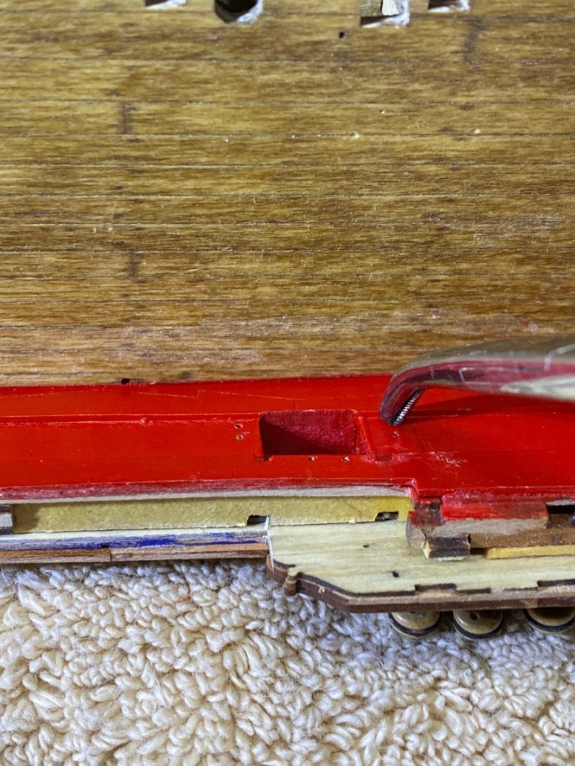
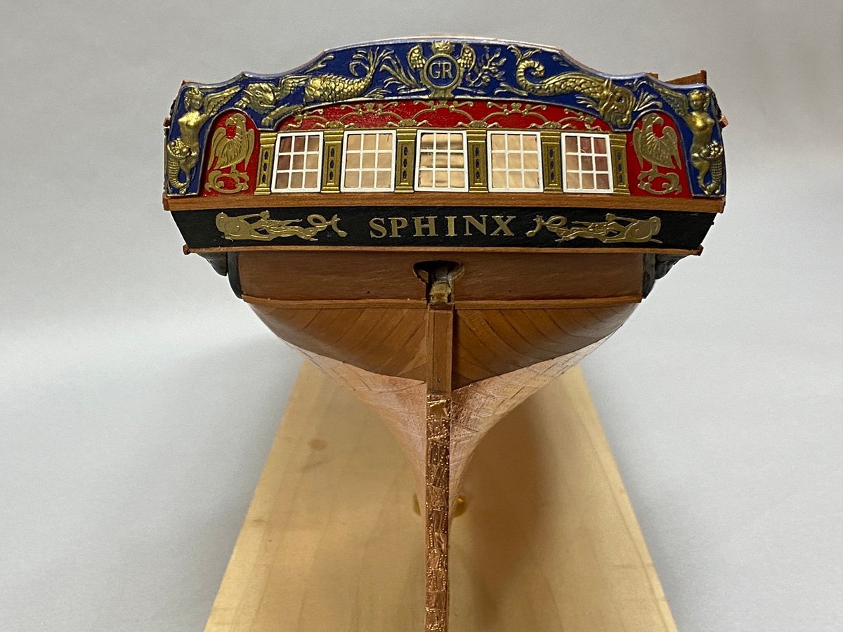
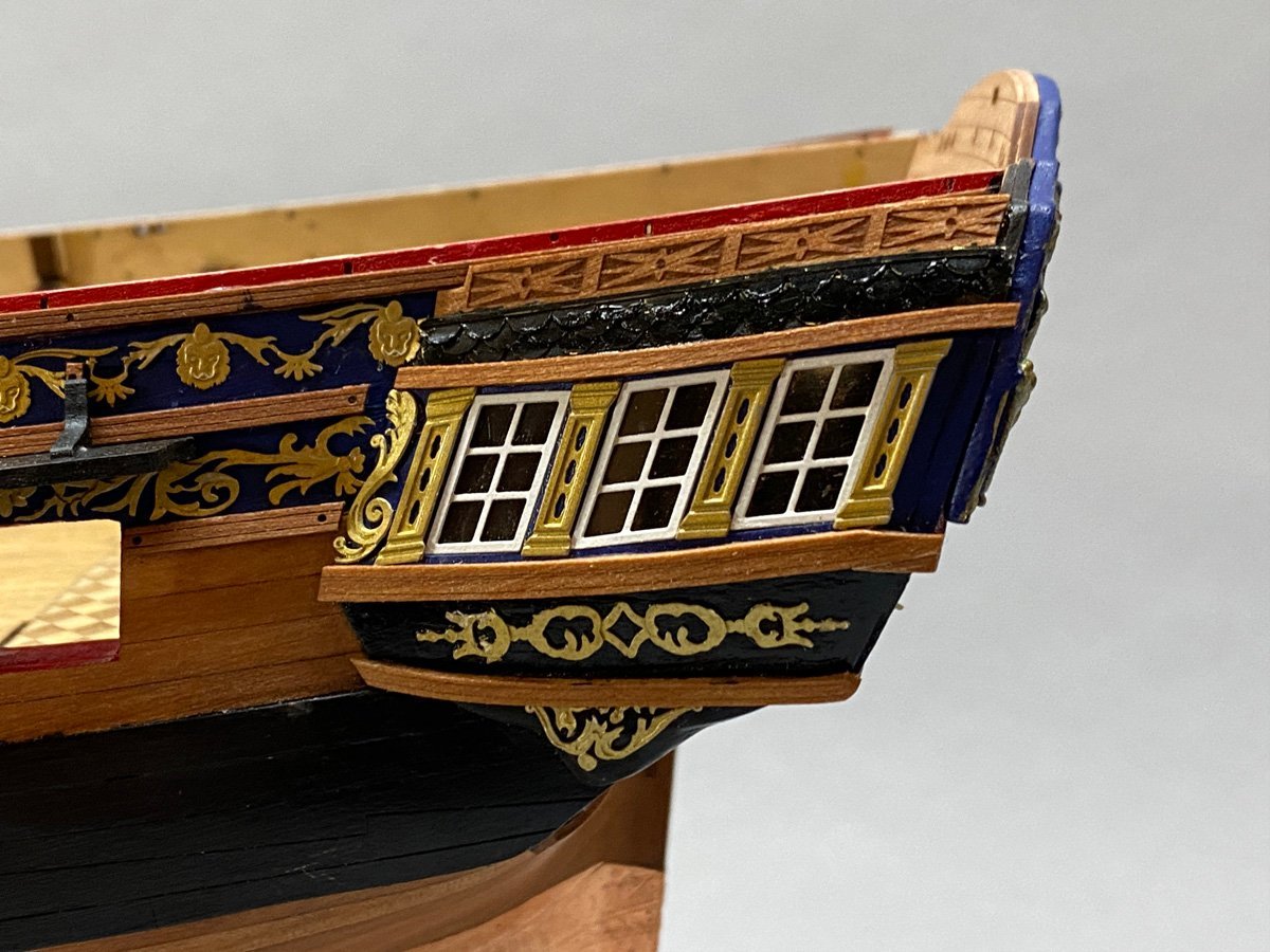
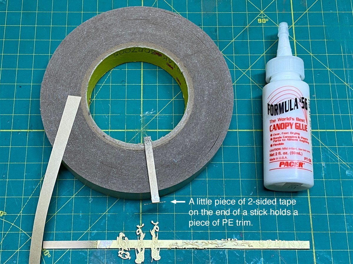
Stern Details One advantage to having a fixed base is that you can do this: All the details on the stern are pretty intimidating, but you just jump in and start attaching parts. Speaking of attaching parts, I have been using canopy glue to hold the PE parts in place. Canopy glue is what RC modelers use to attach their canopies. It looks like plain white glue but it has an aggressive tack, dries clear, and is strong enough to hold a canopy on a fast RC model. It's also what @ccoyle uses to built card models. I use 3M double-sided tape to hold parts to scrap sticks for painting, and also attached to a small stick to hold parts for placement on the model.
- 96 replies
-
- 8
-
-
- Sphinx
- Vanguard Models
- (and 2 more)
-
Hey Mugje, I just ran into a problem where my rudder with the tiller arm wouldn't fit into the opening in the hull. I had to remove about 6mm of the rudder post to make it fit. I recommend removing the main rudder piece from the 3 mm sheet now to see if it fits. It will be easier to fix now than later.