georgeband
-
Posts
307 -
Joined
-
Last visited
Content Type
Profiles
Forums
Gallery
Events
Everything posted by georgeband
-
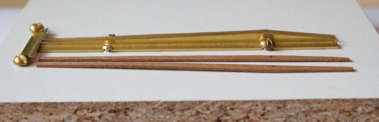
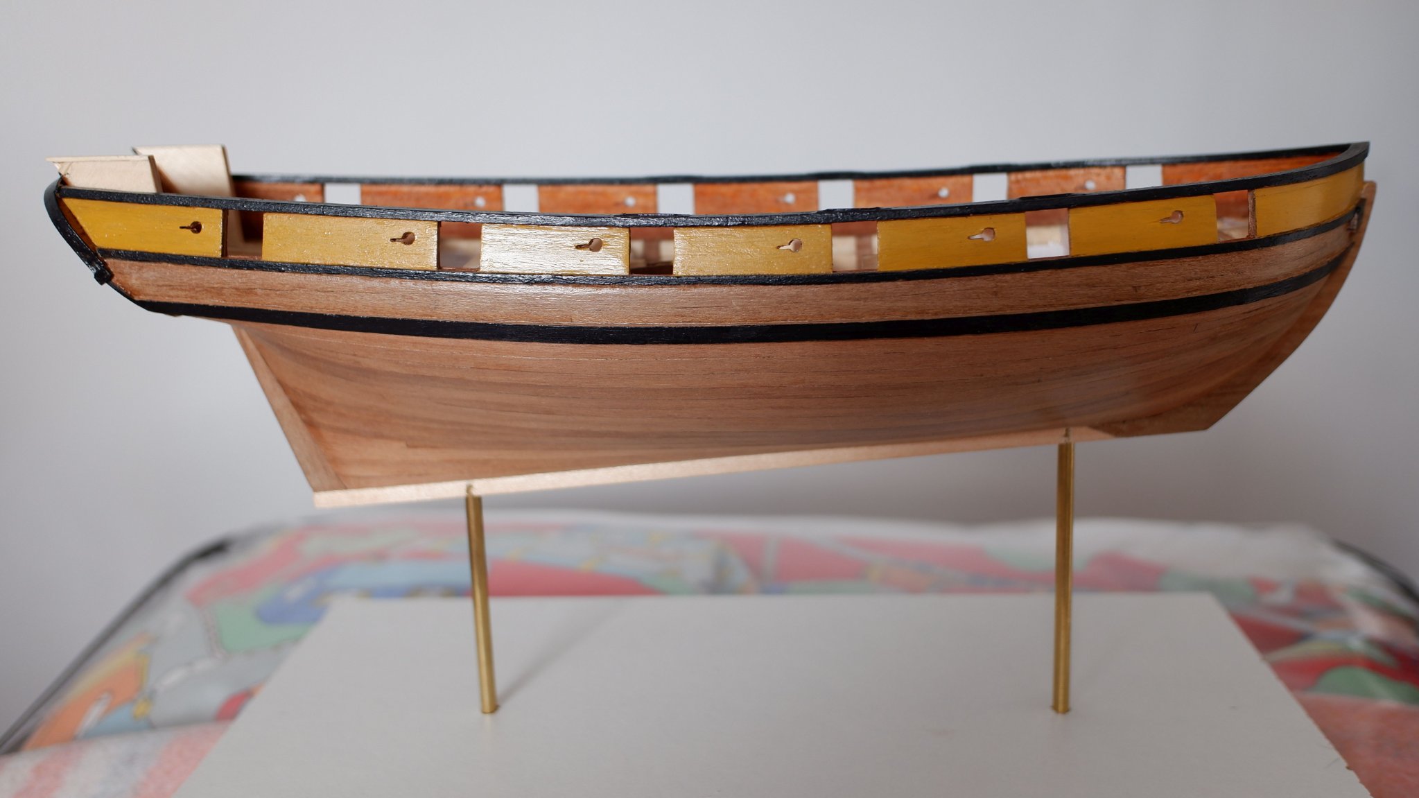
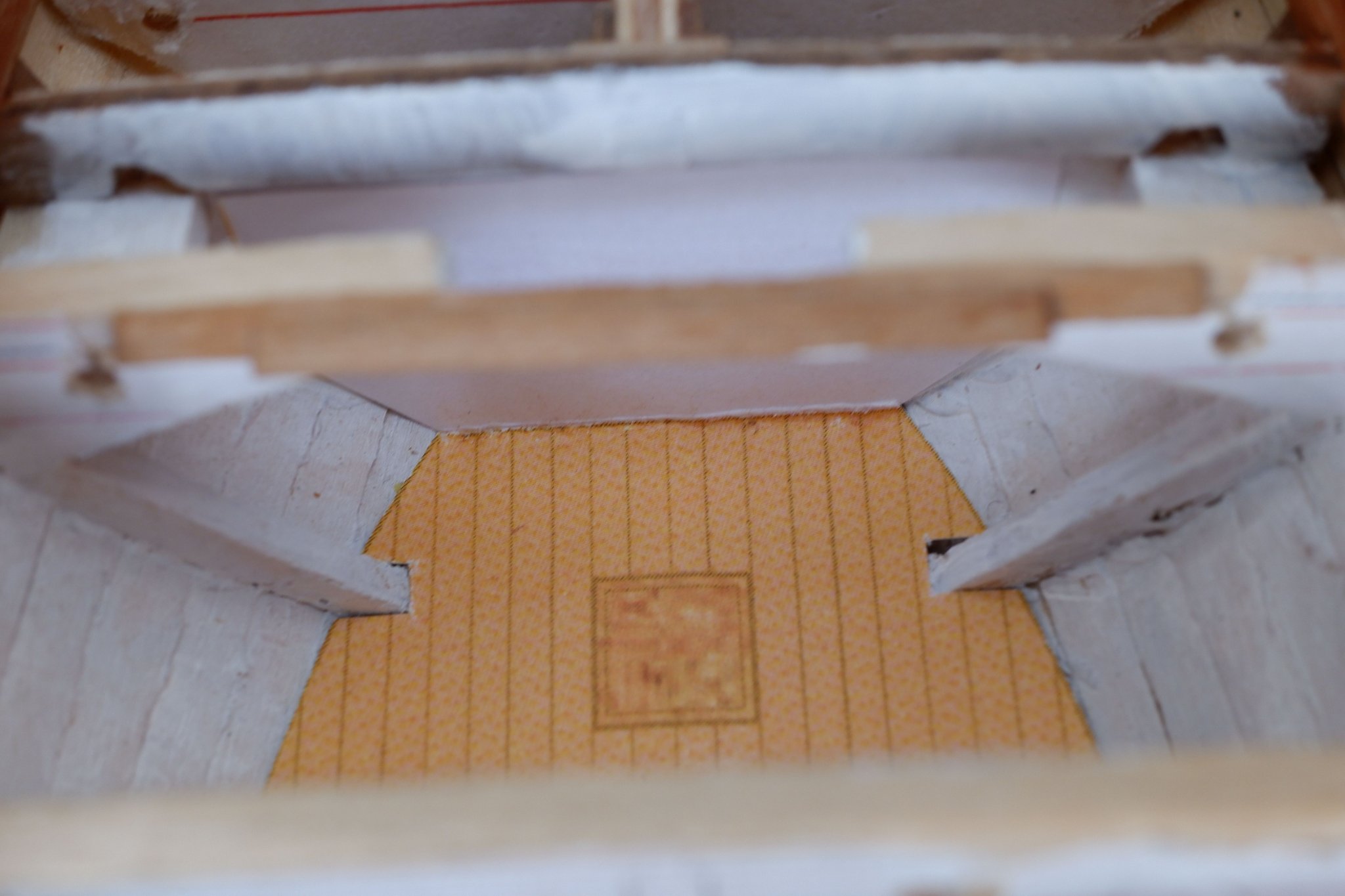
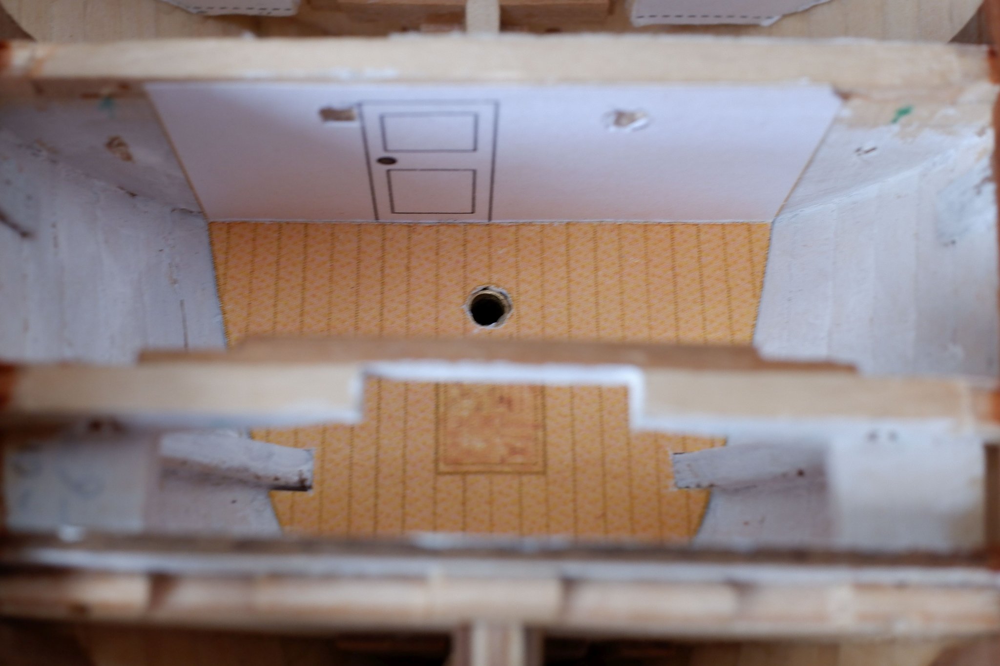
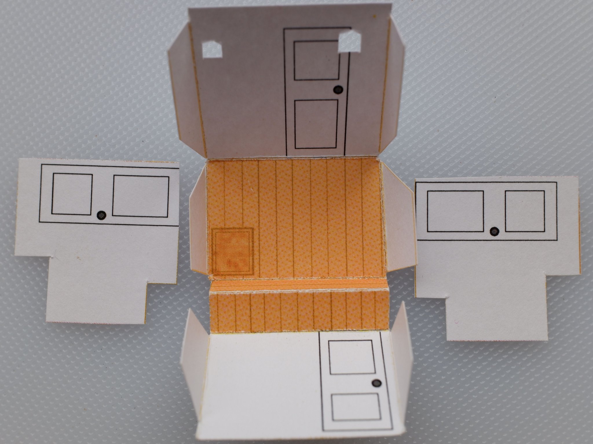
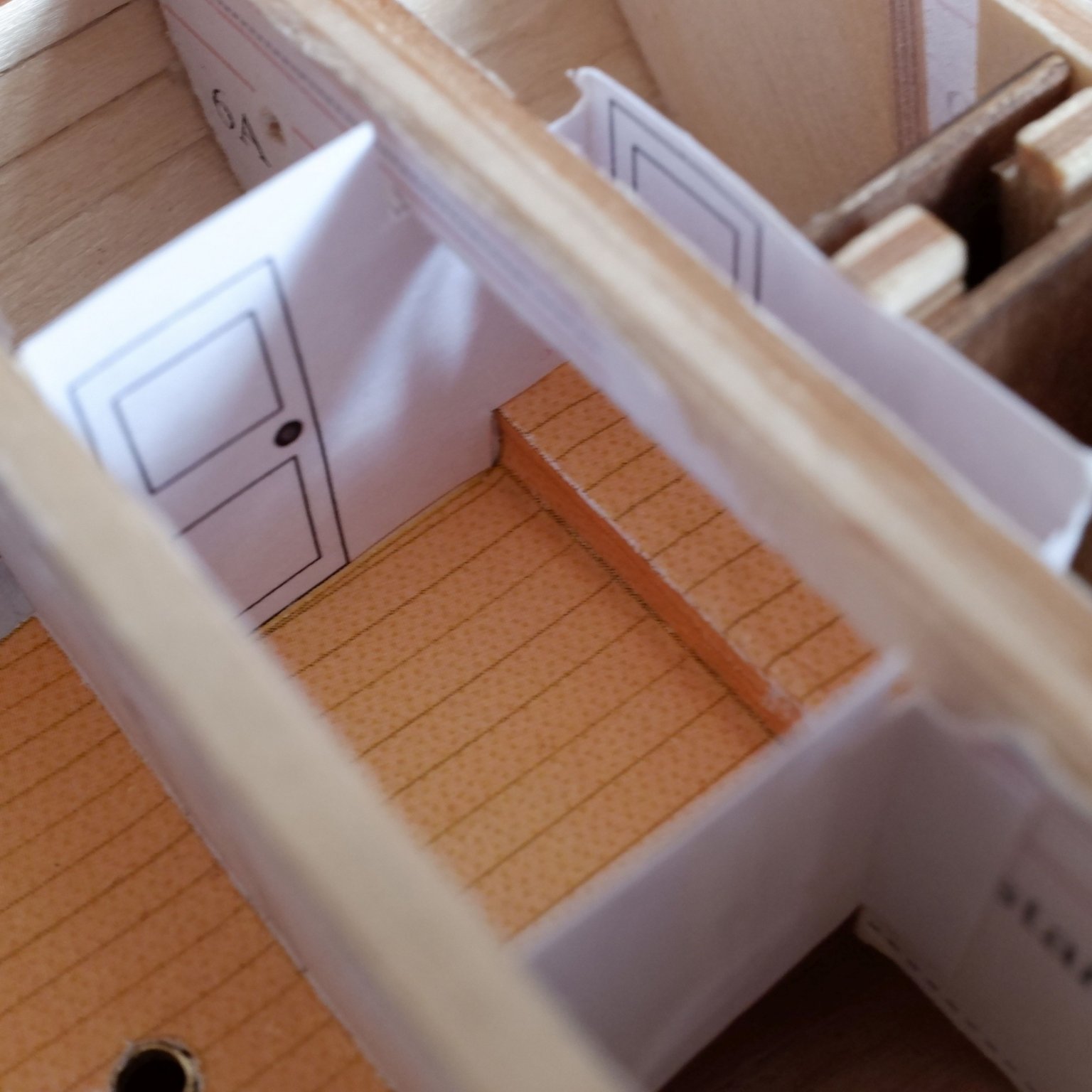
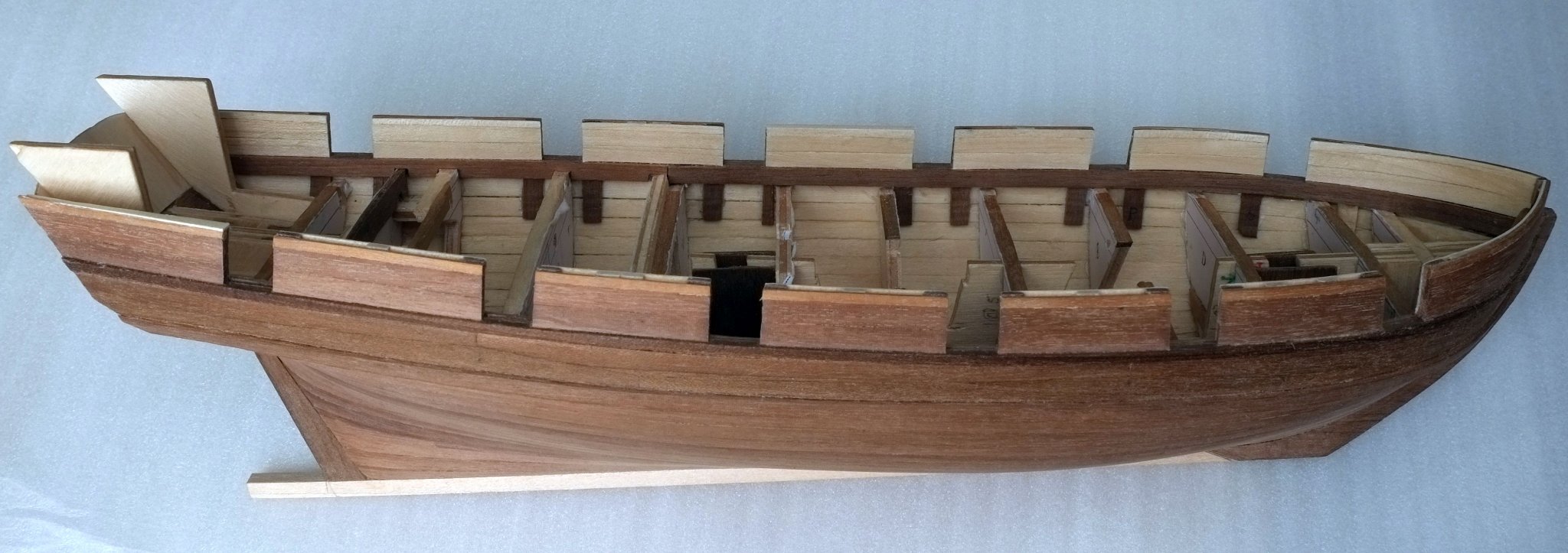
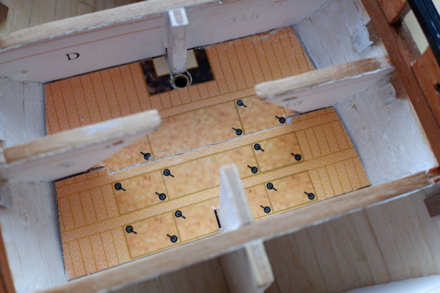
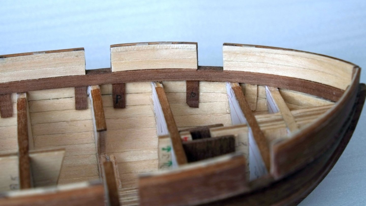
 Whiting now has two lengths of brass tube sticking out of her bottom. These are the stands and I will thread optical fibres through them later. For now they are a push fit into a block of wood and hold the schooner so that her waterline is horizontal. The tops of the tubes are level with the lower decks. The tubes were a push fit into the hull and I secured them with a generous amount of epoxy resin (Araldite rapid) which I poured and poked into the bottom of the hull where the tubes are exposed. The next time consuming job was to design interiors as card models. The Admiralty drawings have plenty of detail about the lower deck(s) and I used Powerpoint to replicate them. This work was iterative with trial prints on paper, test fits and large and small adjustments until I was confident that I could get the folded card into the confined spaces between the bulkheads. The colour of the floors was also by trial and error and I wanted to match sanded Eastern Red Cedar which is the closest available alternative to Bermuda pencil pine. The walls I left in white on the assumption that they would be whitewashed to try and get the most light into the spaces. The captain's cabin was the simplest card model and it has a floor, front wall and back wall all in one piece. I painted the sides of the cabin white. That's when I learned that the inner face of the hull was called the ceiling. Captain's cabin looking aft. There is a scuttle in the floor. Captain's cabin looking forward. The hole in the floor is where optical fibres will come in. The large space between frames B and D aft of the fore mast was made in two pieces because a single piece cannot be inserted between the sloping cuts in the spine and bulkheads. View forward. The black area is the floor below the cooking range. I will disguise the hole with a bucket or something. Lots of hatches in the deck. The entrance lobby is the most complicated card model and I used one piece for the back wall, floor, step and front wall. Two separate pieces are needed for the sides where the sub-lieutenant and surgeon have their cabins. Parts for the entrance lobby. The holes in the back wall are for optical fibres Entrance lobby, view forward and to port Let me know if you want a pdf copy of the card models for the interior. I will put it on my website at some stage. The improving weather here means that model making will slow down for a few months while I tackle full size jobs around the house. I hope that a few rainy days will let me work on furniture and lighting at 1/64 scale. George
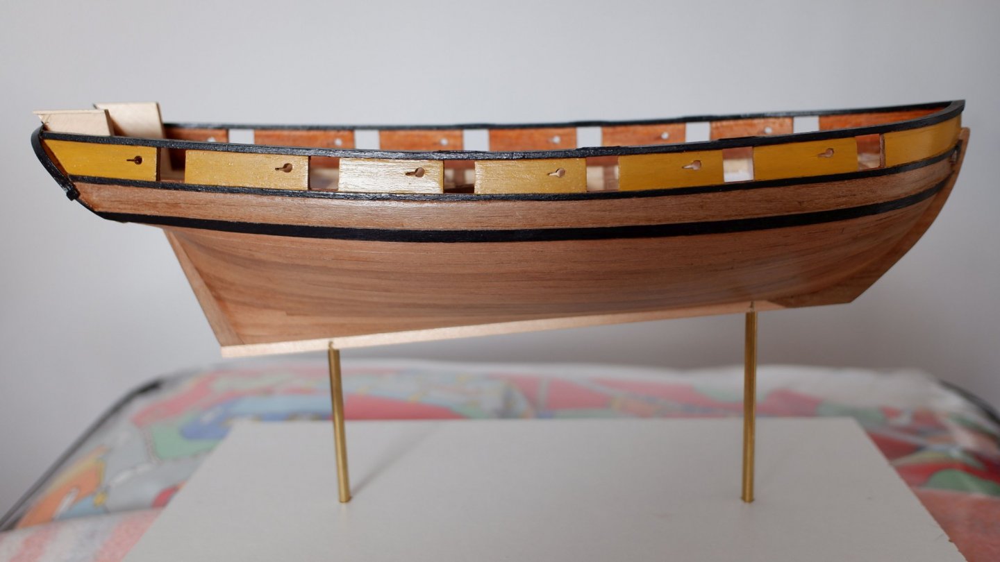


-
Sloping deck
georgeband replied to Don Case's topic in Building, Framing, Planking and plating a ships hull and deck
I had a quick look in Falconer's universal dictionary of the marine (1784) and he said Falconer's definitions for 'rounding' have nothing to do with curvature so the term probably emerged in the late 1700's or early 1800's. JJ Moore had almost identical wording in his dictionary printed in 1801. Plagiarism was rife back then and still shows its ugly face now. Both dictionaries can be found on the web as pdf files. George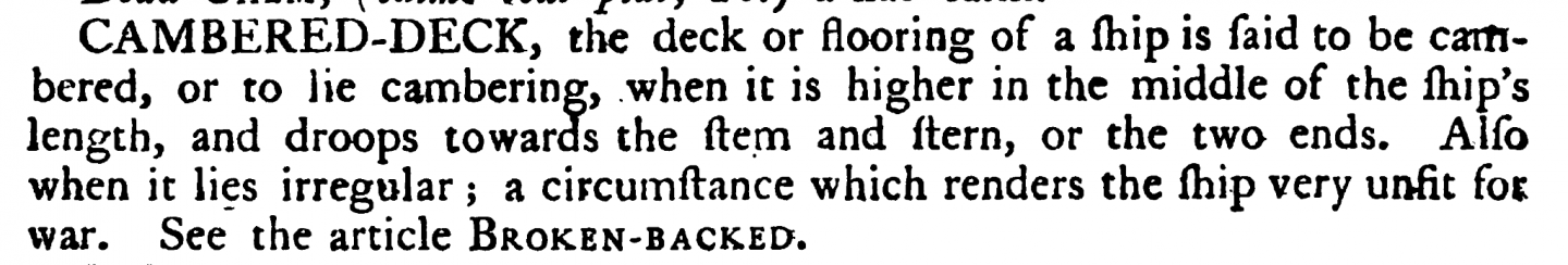
-
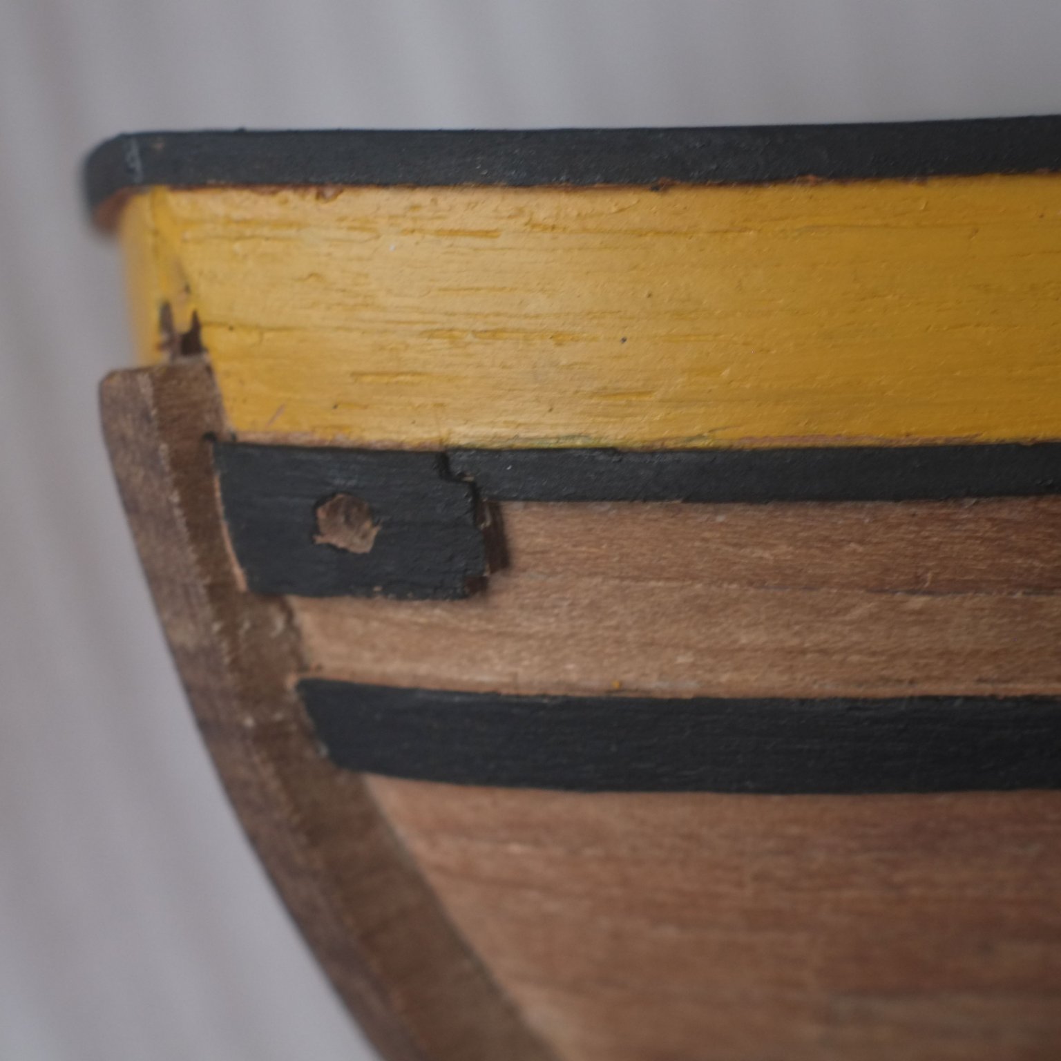
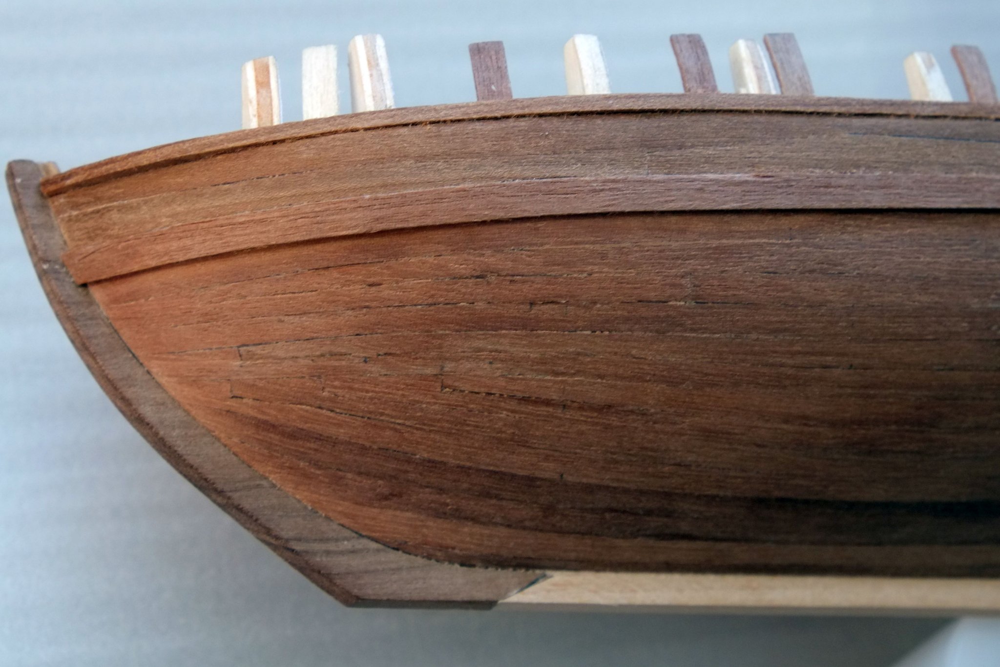
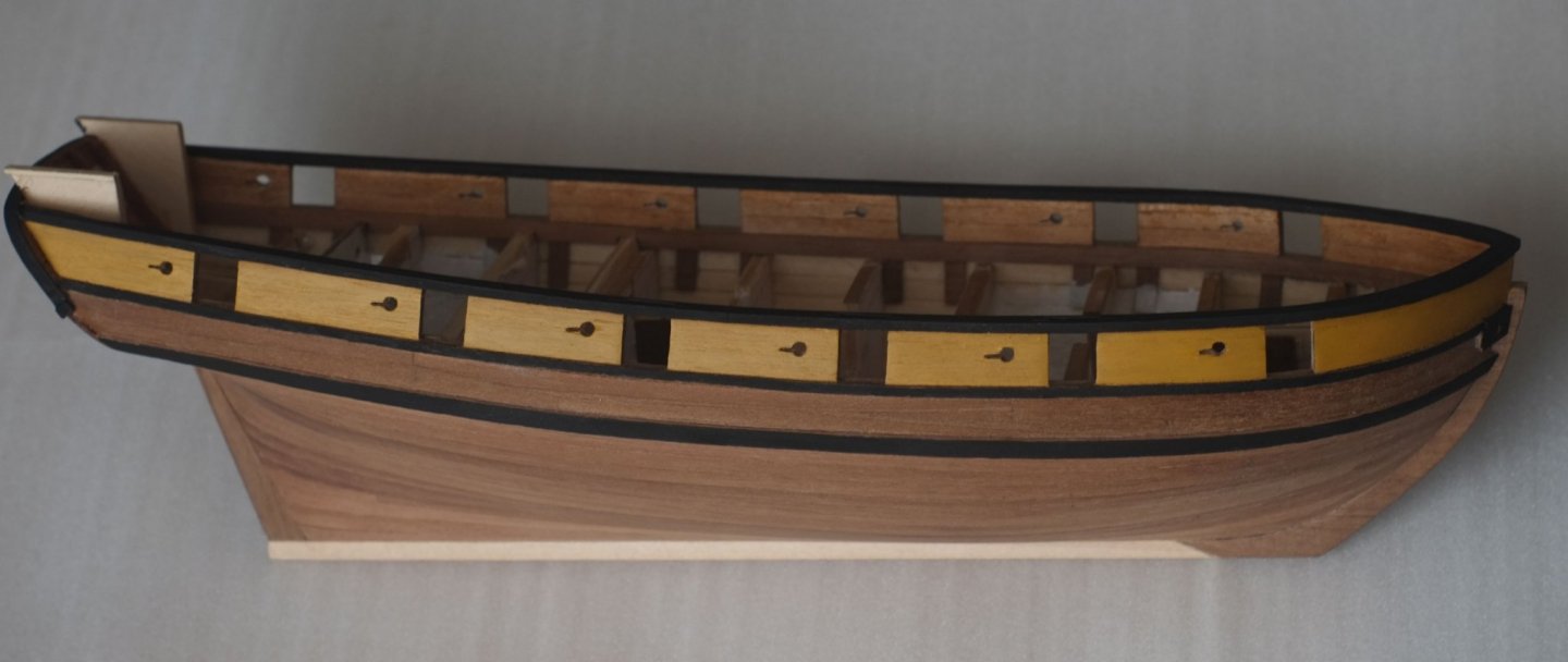
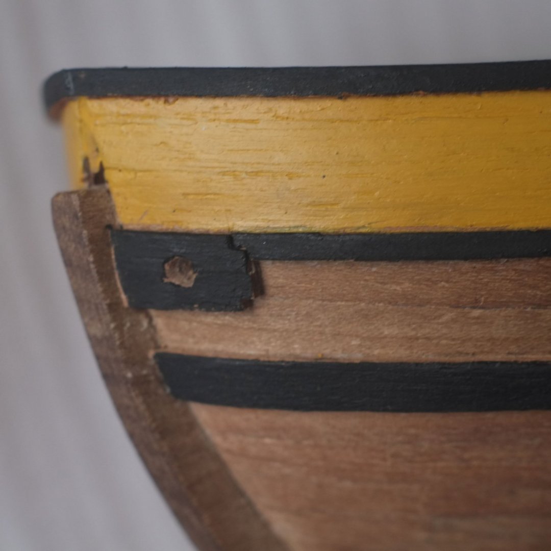
The hull has had its first coats of paint. I chose to paint the bulwarks in yellow ochre and the wales are black; this is a simple guess based on the idea that these colours were cheap and could be afforded by a newly promoted lieutenant. I took the idea a bit further and the gunwale is black on the top and sides while the wales are black on the sides only to save even more cost. I used acrylic paints (Rowney artist) and thinned them to get an even finish. The yellow ochre needed six coats before I was happy with the results and fortunately with acrylics the waiting time between coats is quite short. I also made the hawse hole covers from walnut planks glued together for width and for thickness, then carved to get the right shape and a good fit against the hull. They are only two little pieces but it took me the best part of three hours to make and fit them. Drilling the holes was the easy bit. My earlier, careful work on scarph joints in the gunwales has been largely obscured by the paint but the reinforcing bars over some of the gun ports can just be made out. Detail features that are painted black on a black background have little chance of standing out. George
-
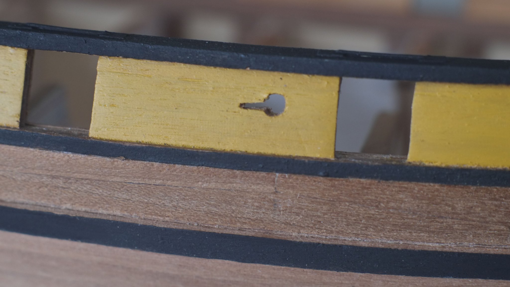
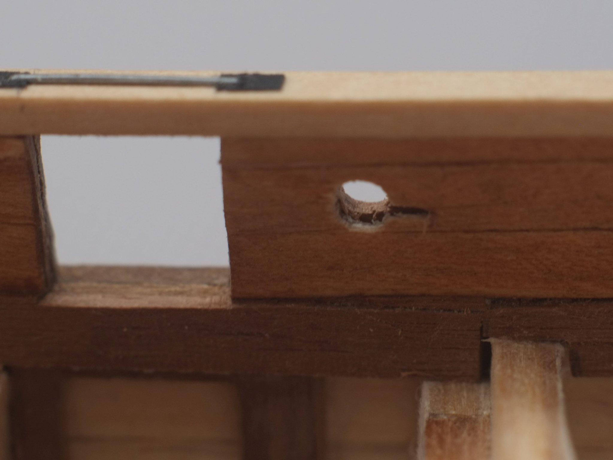
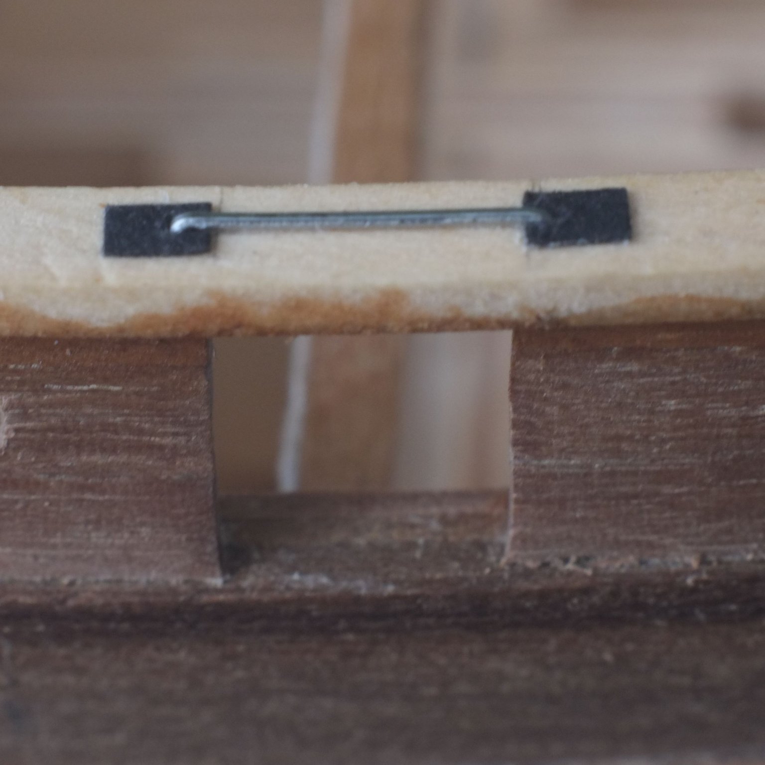
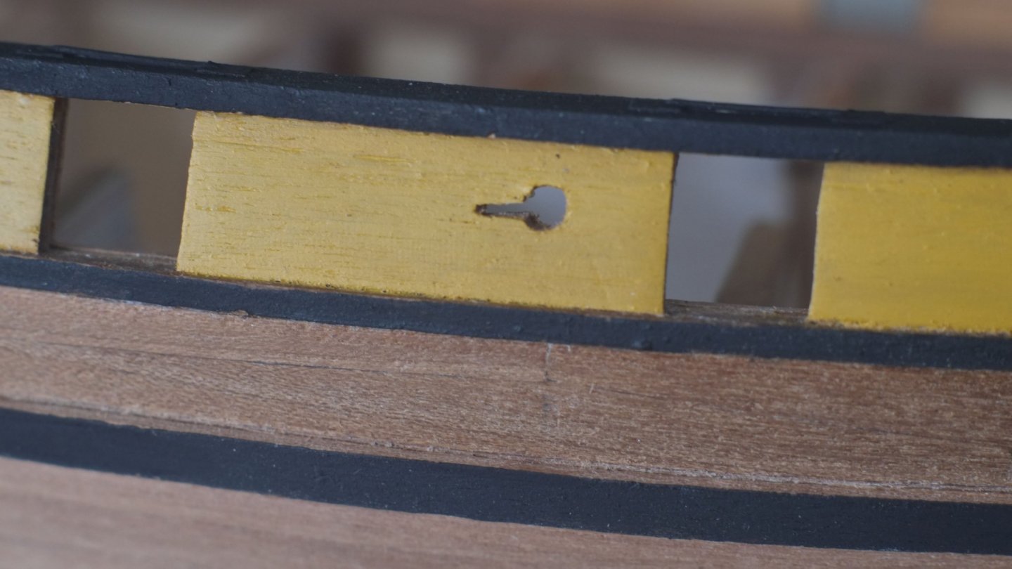
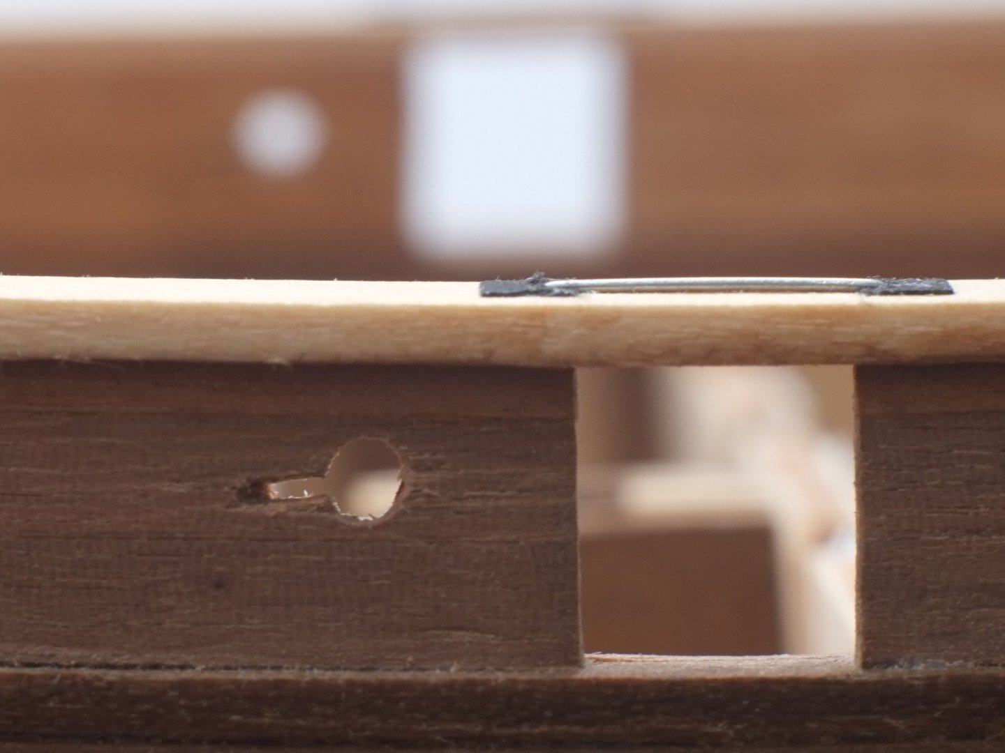
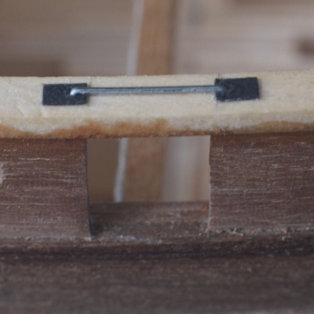
I have completed some detailed work on oar ports and reinforcing bars above the gun ports. The reinforcing bars are shown as a horizontal dotted line on one Admiralty drawing. My interpretation after guidance from other MSW members is that the ends were iron plates which were set into the gunwale (also known as the cap-rail by some). The reinforce itself is probably a bar but could be a rod; there is not much difference at 1/64 scale with a 2-foot viewing distance. The iron plates are rectangles of card and the bar is a staple that has had one leg straightened and then bent again to give the correct spacing. The oar (sweep) ports are keyhole shapes on the drawing. The round hole was easy to make by drilling and trimming but the slot was tricky because it is less than 1mm wide. I drilled a couple of 0.5mm holes to start the slot then joined and extended them with delicate knife work. There are 12 of these ports on the schooner and every one has to be good, and there is no option to make more and choose the best ones. (The gun ports are 9mm wide to give you a sense of the scale.) I found it essential to work with an illuminating magnifier for these. The gunwale will get a coat of black paint, as will the other wales. I will probably paint the outside face of the bulwarks between the gunwale and the upper wale in yellow ochre. The inner face of the bulwarks is currently stained with walnut and I think I will leave it natural. John Roach's log book mentions painters coming on board but he did not record what they painted or in which colour so the choice is fairly open. George

-
This is how I modelled the 'gunwale reinforcement' on Whiting. It took a while with rectangles of card and a staple that I re-bent to give the correct spacing between the legs. The gun port in the photo is 9mm wide. I have also made the oar ports and describe them both on my build log. This episode shows the consequences of looking at original documents where a dotted line can generate discussion and modelling time. Thanks all for your help. George
-
Topsail schooner sail plans and rigging
georgeband replied to Dr PR's topic in Masting, rigging and sails
I use Powerpoint for simple illustrations and the reason is familiarity with the software through work. I am sure that 'proper' drawing packages can do much more but for an occasional user like me I would have to climb up that learning curve again after a break of 6 months or a year. A package that offers 3D would be nice but I don't particularly want to assign the time that I would need to master it, especially when there is competition from other things to do. It would have to be very intuitive. George- 104 replies
-
- 3
-

-
- schooner rigging
- Topsail schooner
- (and 1 more)
-
Gunwale or cap-rail? Now I am confused. The references I have talk about a gunwale (or gunnel) as being "the upper edge of a ship's side". This goes back to Moore's and Falconer's dictionaries and is also in the more recent works I have. I have not come across cap-rail previously. Could this be some trans-Atlantic variation, or a more modern term? It's interesting how language evolves. George
-
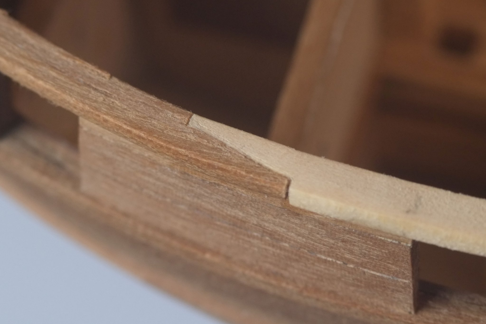
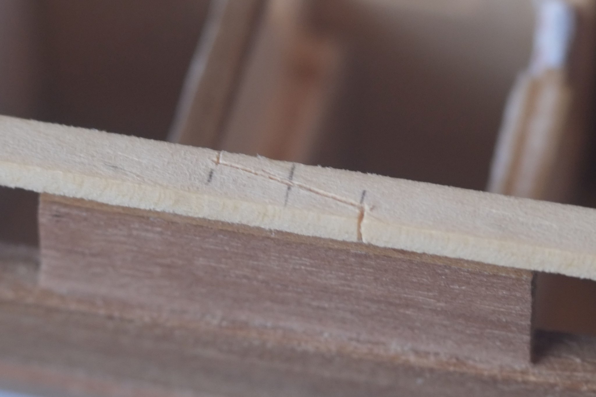
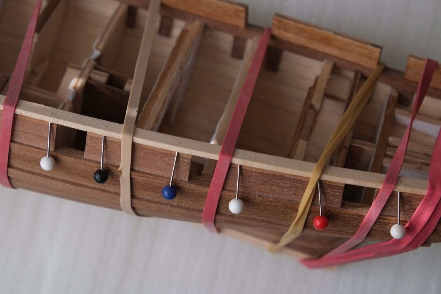
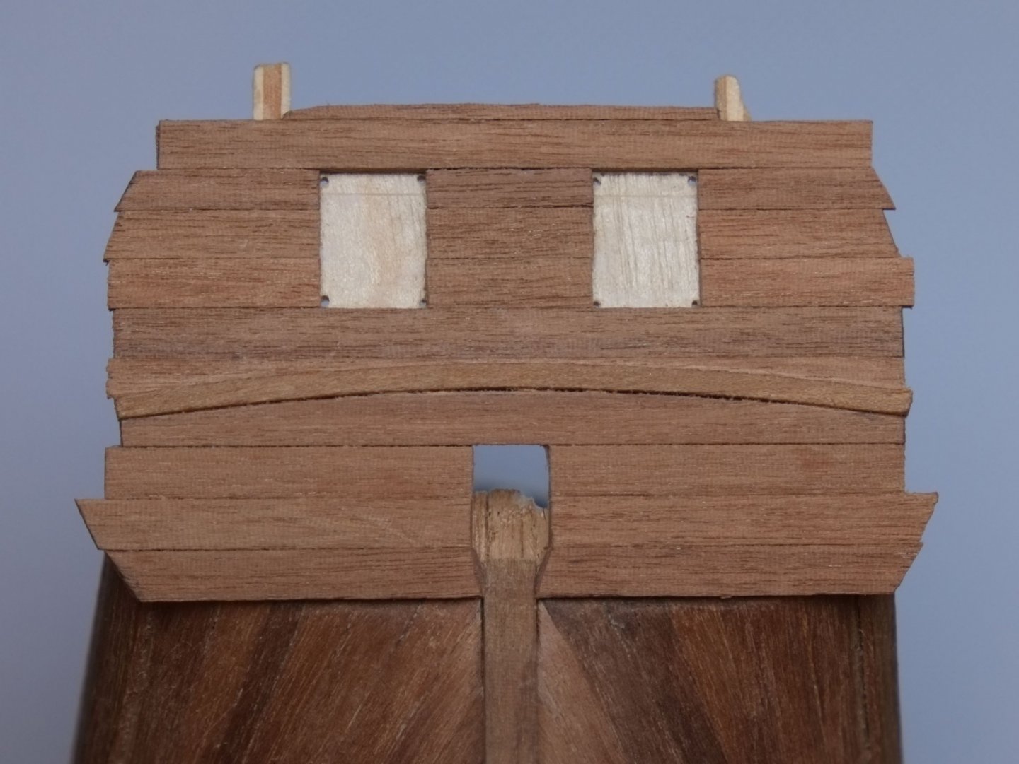
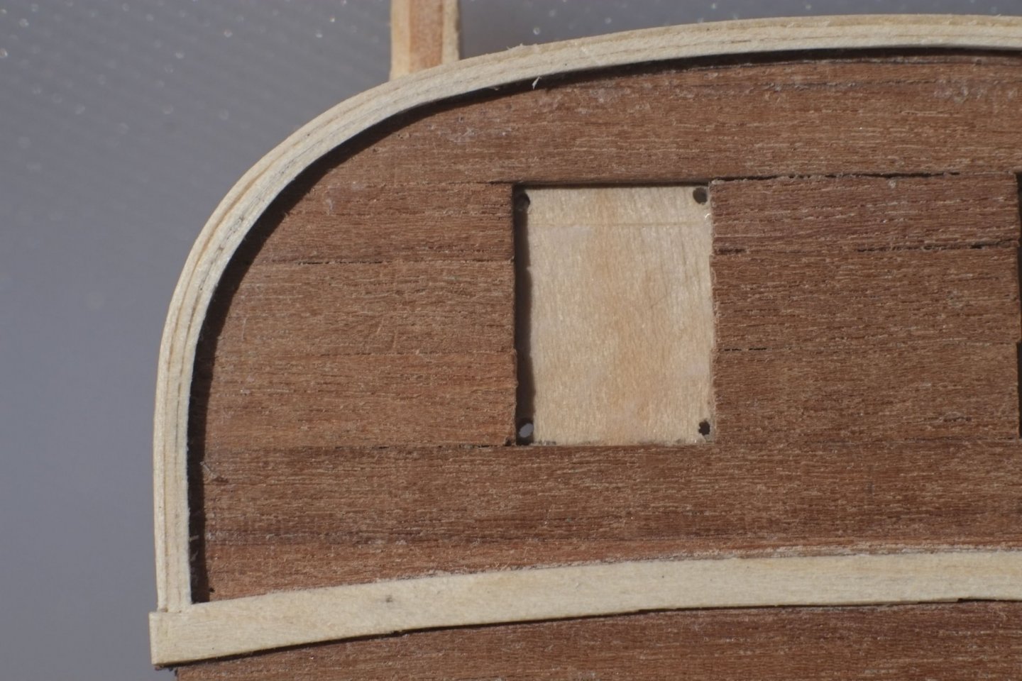
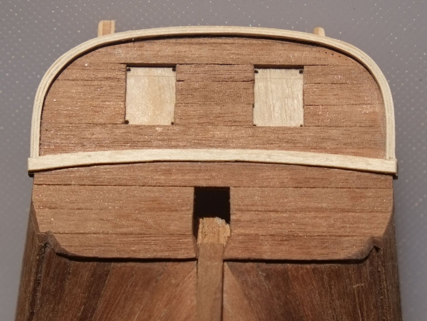
More building to report. The gunwales are now in place. The relatively straight sections are in 2x4mm lime wood and have two fake scarph joints scribed on them. The fore ends of the straight bits have a real scarph joint where they meet the bow sections. I soaked and bent the gunwales to shape, then put a row of pins in the underside of them so that they would not slip sideways while they were gluing to the tops of the bulwarks. The fore section of the gunwales over the bow has a tight curve and I made them by laminating two 2x2 pieces of walnut which were individually bent to shape. I used two different lengths of wood and found that for one them 2x2 was not quite right and I had to add a third layer to get the correct width. That's why the photo below shows a pale inner face to the bow section of the gunwale. I will paint the gunwales later. I sanded the inner and outer edges of the gunwales to get the angle (parallel to the bulwark) and the overhang right. The transom revealed a mistake I had made with the ply former which should have been 2mm higher. I cut and edge-glued an extension before planking the outside faces of the counter and transom with a generous overhang at the sides. Between the counter and transom is a 2x2 piece of walnut, glued to the face of the transom. I then drilled holes through the corners of the gun ports to give datum marks on the inner face. (The photo does remind me of an owl.) The inner face then received four uprights (2x2 walnut) and planking that matched the outer face. For the inner face planking I used 0.5mm deck planks to keep the thickness down. I also planked the forward face of the transom where it projects outside the bulwarks with 1mm walnut. The schooners had 'wings' on the transom which I think were fashion statements. On the model they are 2mm thick and I sanded them to shape. There was a frame around the transom and at the top-centre I cut in a piece of 1x4mm walnut. A piece of 0.5x4 deck plank then went around the whole transom. Once the glue had set I put in two extra laminations of the same wood on the inside face of the frame. Careful sanding afterwards left a nice lip around the transom. I also glued a layer of 0.5mm over the join between the counter and transom to build up its thickness. The gun ports in the transom remain blocked with thin ply. I still have not decided whether they should be open or if they should have port lids. If I do choose closed lids then I will plank onto the ply to represent them. George

-
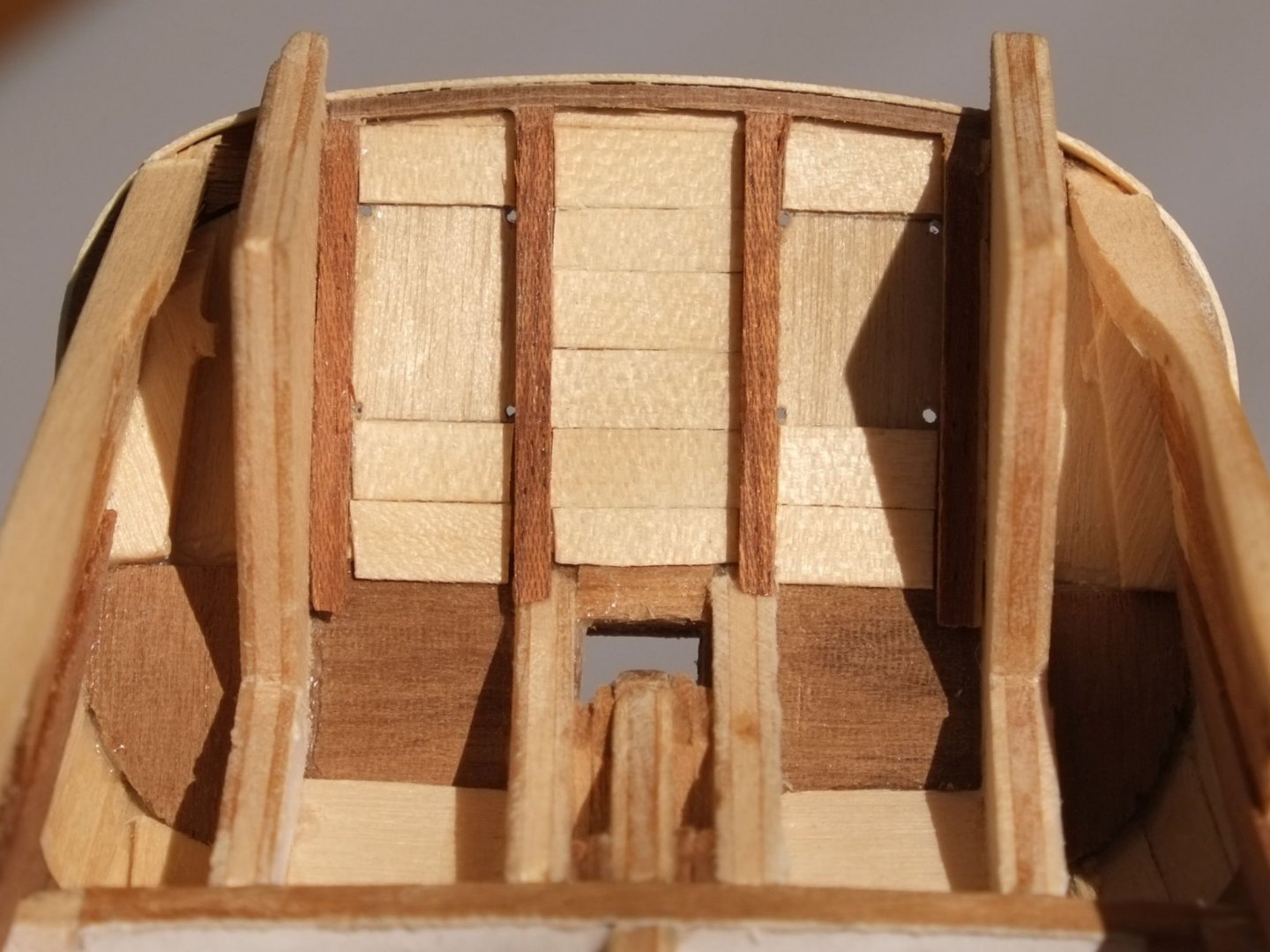
I have built the counter and transom on Whiting and postponed a decision about the chase ports. At the moment there is some thin ply filling the gap which I can cut out or plank to mimic a closed lid. Part of the reason for hesitating is that there are some good looking models of the cutter Cheerful (also 1805) which show her with port lids. I have to dig a little deeper in this vein to find the thinking behind this approach. I would appreciate even more comments and advice. I drilled holes in the ply former for the transom to align the planking on the inner and outer faces. The thick ply structures at each side are the side walls to a pantry (starboard) and the 'necessary' to port. George
-
I made my decision about scarph joints and chose a simple design. I have put three joints on each gunwale, fairly evenly spaced along its length, and each centred between two ports. One on each side is a real joint where I changed from a relatively straight piece of lime wood to laminated walnut which I used to go around the curve of the bow. The straight sections have two fake scarph joints scribed on them. I will paint the gunwales later so the laminations and changes of wood will not be visible. I have abandoned the swarm of Caldercraft timber heads though I will put something near the tip of the bow, likely to be a couple of timberheads or a short pin rail. It depends on the rigging plan when I get round to defining that with more extrapolations and guesses. The iron rails over some of the gun ports are also yet to be fitted. George


-
Mark, I agree with you entirely about researching old manuscripts and I am building a collection to write a full history of Whiting. Some I have found on the internet but the majority are from the National Records Office at Kew. I look forward to the day when I can go there again and photograph more log books, pay books, muster lists and so on. Regards, George
-
Topsail schooner sail plans and rigging
georgeband replied to Dr PR's topic in Masting, rigging and sails
Phil, Simply outstanding. Thank you. George -
Topsail schooner sail plans and rigging
georgeband replied to Dr PR's topic in Masting, rigging and sails
Phil, Thanks again for your work which is culminating in the spreadsheet of doom. There is a vast amount of information that you have compiled here and I for one will make use of it. I have one more request which loops back to comments of yours when you embarked on this voyage: you said that most of the references did not define their terms such as 'length'. You did this earlier with some useful diagrams and it would be helpful to include these in the spreadsheet. When I open the spreadsheet again in several months it will save some time and puzzled head scratching if the pictures are there on one of the tabs. My thanks once more for saving me a job and doing it so well. Regards, George- 104 replies
-
- 2
-
-
- schooner rigging
- Topsail schooner
- (and 1 more)
-
I have had a look on Abebooks and they point me to a copy of Caruana which is for sale in Hamburg. The price is very precise in UK£ and is probably calculated from 1000 Euros. That's a bit more than I can justify. George
-
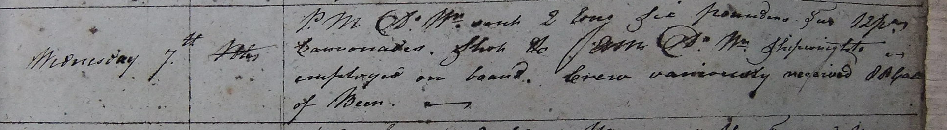
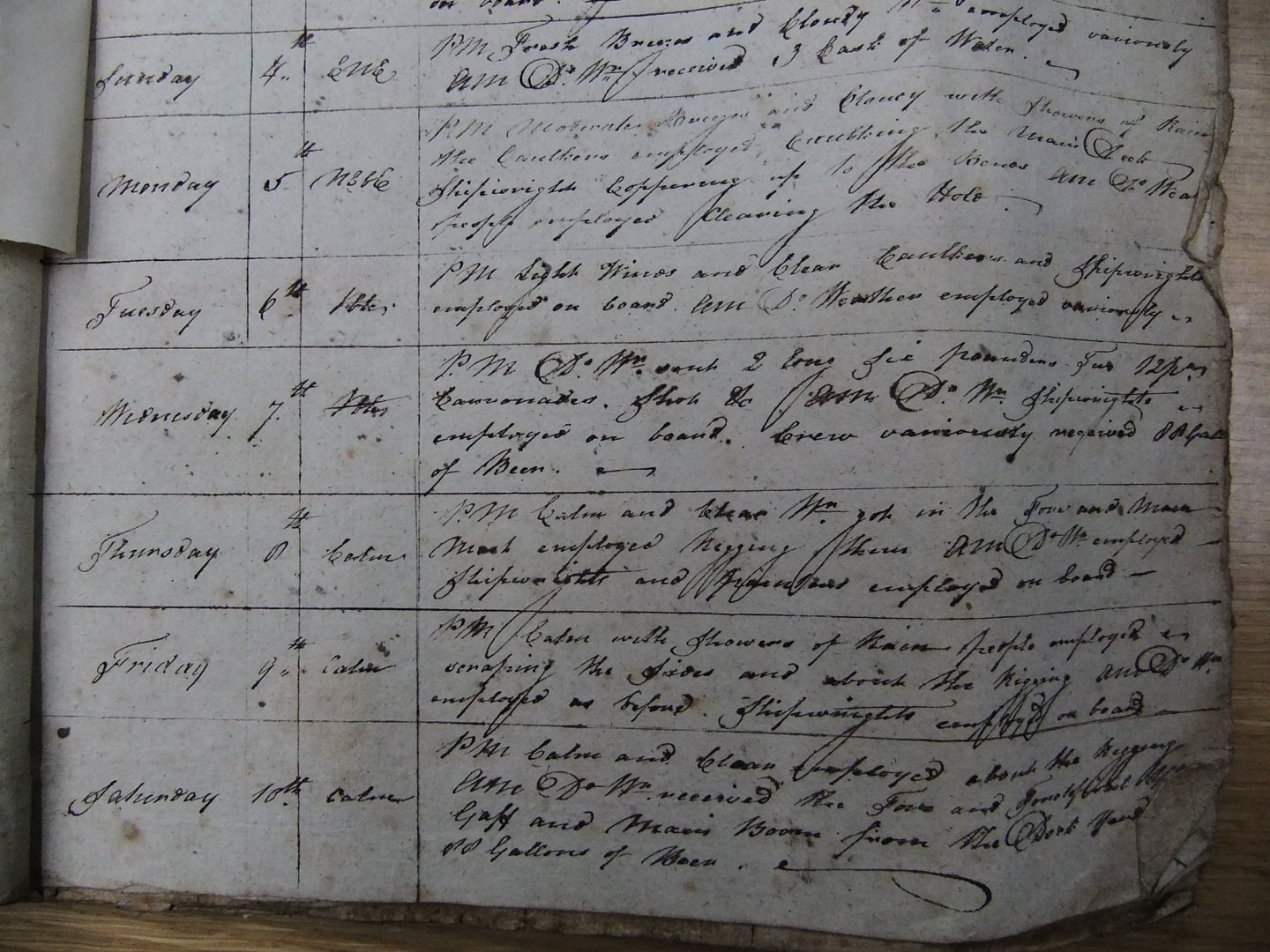
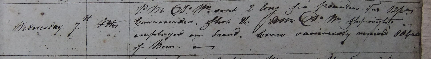
Mark, It is easy to get absorbed into translating a hand written log. Sub Lieut Roach has poor handwriting compared to others I have worked on, and he also has bad days where the writing is large and scrawled, and other days when it is very fine but still hard to make out. My transliteration came out as PM Do. Wr. Sent 2 long six pounders Two 12pdr carronades, Shot etc. AM Do. Wr. Shipwrights employed on board. Crew variously received 80 Gall of beer The log has the afternoon (PM) first because the navy day started at noon and the morning (AM) came second in the day. Do. Wr. is common. Do. is short for ditto which is a repeat and Wr. is short for weather, so Do.Wr. means the weather has not changed. The log always starts with the weather. 'Sent' is my guess. 80 gallons of beer is not unusual and other days mention beef and water. Punctuation is poor or missing so we have to assume that there is a full stop (USA period) between variously and received. Here is a bit more from the page for you to enjoy. On other days, presumably when John Roach was actively in control, there is a page or two to a day. The entry for 6 May is easier to read PM light winds and clear Caulkers and shipwrights employed on board AM Do. Weather employed variously It gets easier with practice... I do enjoy this research but the fundamental problems for my model remain open What do the joints in the gunwale look like? Hooked scarph? Simple scarph? Were the carronades on slides or wheeled carriages? Were there timberheads present even though they are not on the Admiralty drawings? At some point I will have to make a judgment call based on what I have read and the wise opinions I have seen here. Thanks to all for your input. George
-
Sziggy, Getting the first planking down is a major step forward and shows the shape of the hull properly. I get a sense of achievement when I pass this step and I am sure you did too. I notice some big gaps between several of your planks. This is normal at the stern where the shape of the hull forces them apart but at the bow I expect the planks to jam closer together. (Do a search on stealers to find out more.) You might have trouble applying filler over some of these gaps. My suggestion is that you fill some of the gaps with shaped pieces of lime wood. This will give you practice in bending planks and getting a good fit which will be useful for the second planking which is less forgiving. For some of the gaps cut a length of lime and glue it inside the hull to seal the back of the gap. This will give your filler something to press against. You could use strips of cardboard on the inside instead of wood to achieve the same purpose. A couple of photos from my Ballahoo. One shows triangular gaps at the stern which I filled with limewood. (The transom and counter are different on mine.) The other shows how I worked out the tapered shapes to get the planks to fit around the bow. Don't forget that we do this for fun! George

- 27 replies
-
- 2
-
-
- Ballahoo
- Caldercraft
- (and 1 more)
-
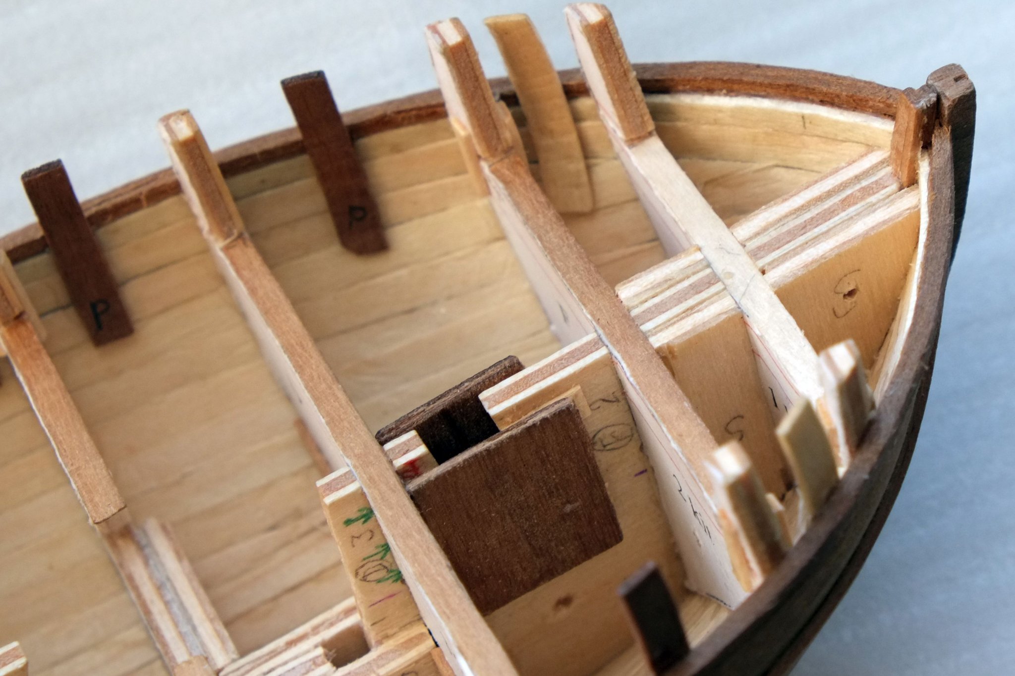
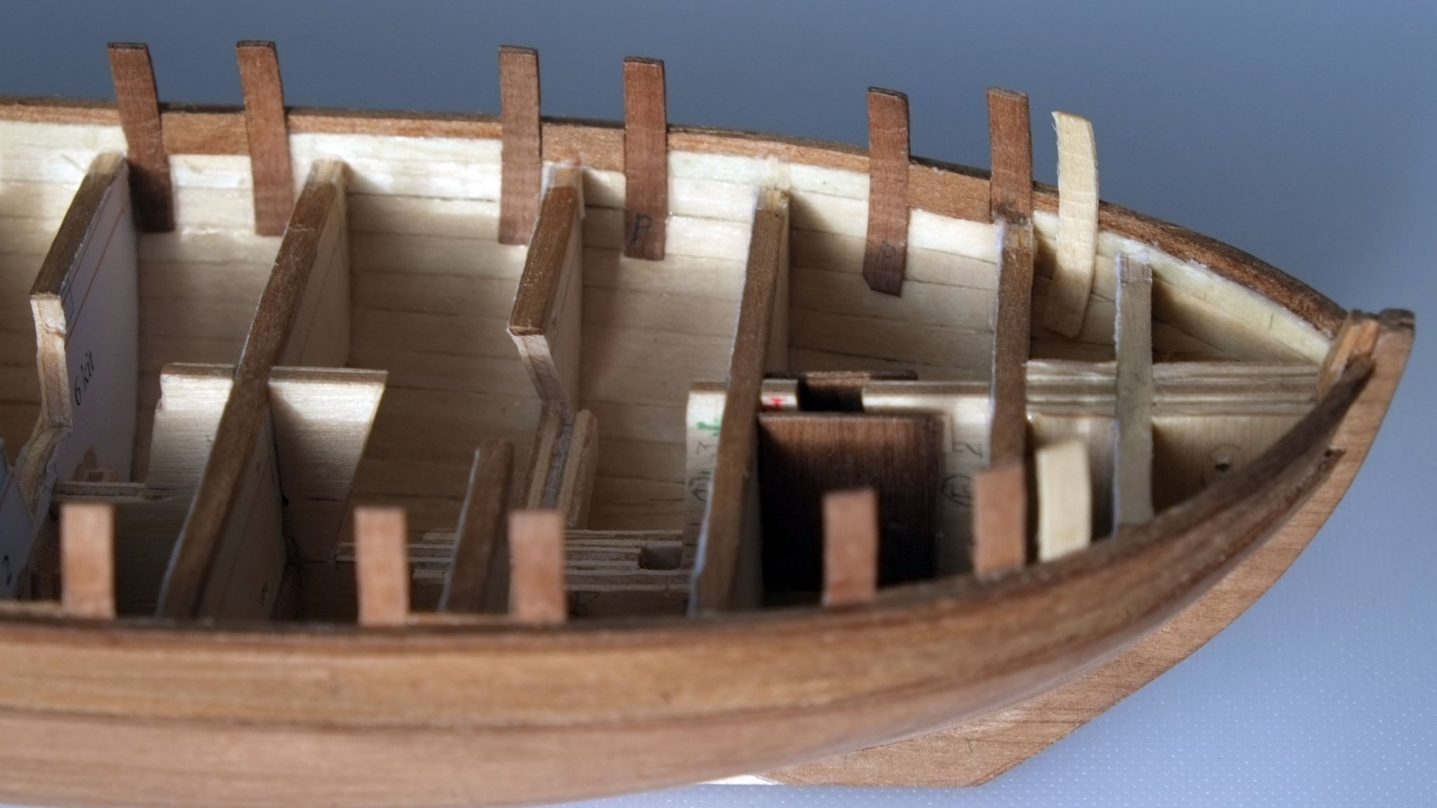
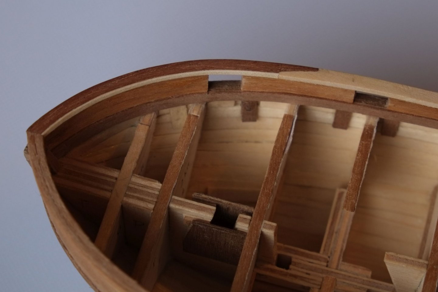
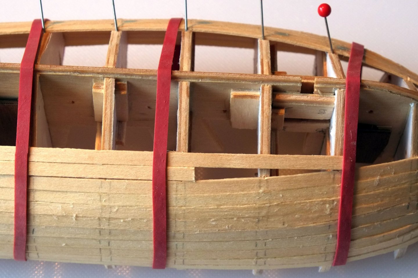
I have now finished the bulwarks and am pleased with the way they curve inwards (tumblehome), something which the kit plywood bulwarks cannot achieve. The design relies on curved uprights that I glued to the inner face of the hull and then planked them inside and out to give a strong structure. The uprights provide the sides to the gun ports but the bulwarks are mostly hollow. (Two of the sections have a pale top. This is because I was a bit too enthusiastic with the sanding and had to build up the height a little.) The outer face of the bulwarks is in 1mm thick walnut. Two rows are 4mm wide and one at the top is 2mm wide. The bottom row sits on top of the upper wale and leaves a narrow step that shows off the wale. The inner face of the bulwark is planked with the 0.5mm thick deck planks from the kit (tanganyika?). The two lower rows are 4mm wide again and the top row is from lengths that I split down to 2mm wide. They look a bit stark now but I will stain them walnut to match the others, or possibly paint them. The spirketting plank below the bulwark planks is 1x4mm walnut and has a narrow, 0.5mm step at the top. Next jobs are the transom and the gunwale. Discussions in a separate thread about the transom (see previous post for a link) guide me towards open gun ports and no name on the back. I have also started a thread about the gunwale and its construction https://modelshipworld.com/topic/27872-gunwale-details-1800-schooner/?tab=comments#comment-799993 It feels like spring here and I am off now to give the lawns their first cut of the year. George

-
Thank for your comments everyone. I am trying to create a realistic interpretation of some dotted lines and rely on evidence from sources other than one Admiralty drawing so I really appreciate your inputs. Frolick, your information about Grecian and Princess Charlotte is exactly what I mean. The very risky alternative is to rely on absence of evidence to try to prove a case. Some other information I have about the gun ports and armament: ZAZ6118 has a cross section of the hull, and notes which state Ports deep 2' 0½" Ports height from the Deck 10½". No mention that some ports are higher than others. The line at the bottom of the gunwale on ZAZ6116 is continuous and smooth and does not show any steps. The accepted wisdom about the designed armament for these schooners is that it was four 12lb carronades. Whiting had two 12lb carronades and two 6lb long guns on 7 May 1806 according to the log book of John Roach. [His hand writing is hard to decipher!] I have not found anything about how the carronades were mounted, whether on a pivoted slide or a wheeled carriage. I live in hope that I will find something in a log book but it has not happened yet. The Admiralty drawings show nothing that resembles a pivot in a gun port, but this is again absence of evidence. For my model I will put a 'stick' of some sort on top of the gunwale over these gun ports. At the moment I think it will represent iron rather than wood, based on my engineering assessment that a thin wooden stick would make little difference to a relatively thick gunwale. Any comments about scarph joints or timber heads? George
-
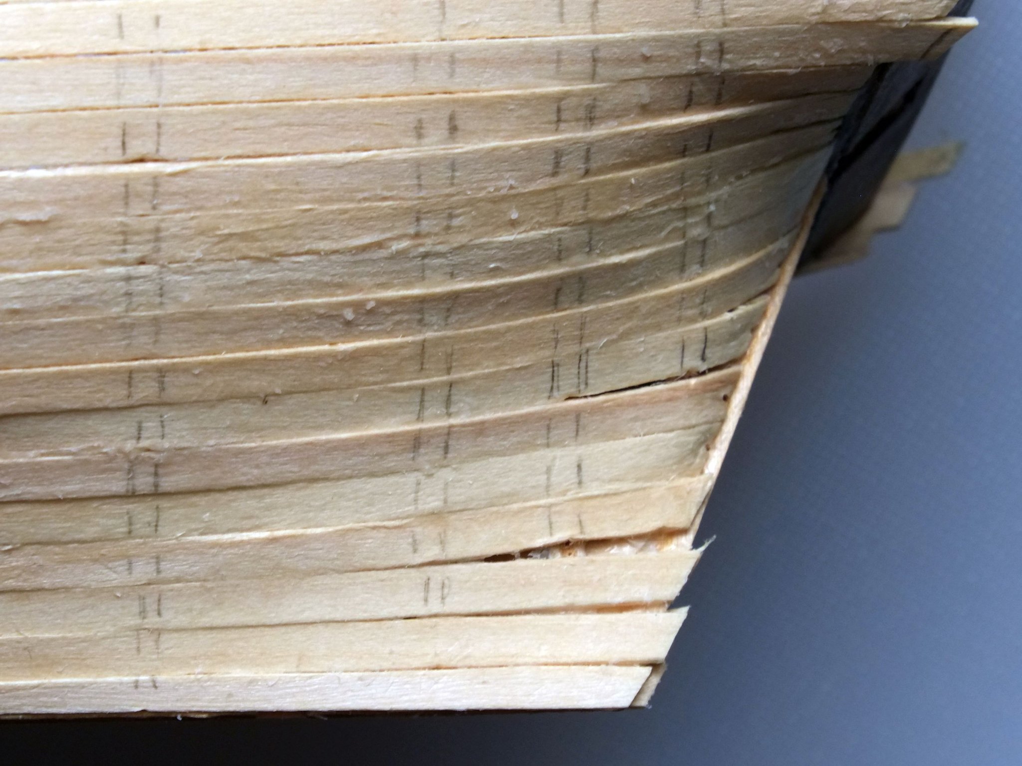
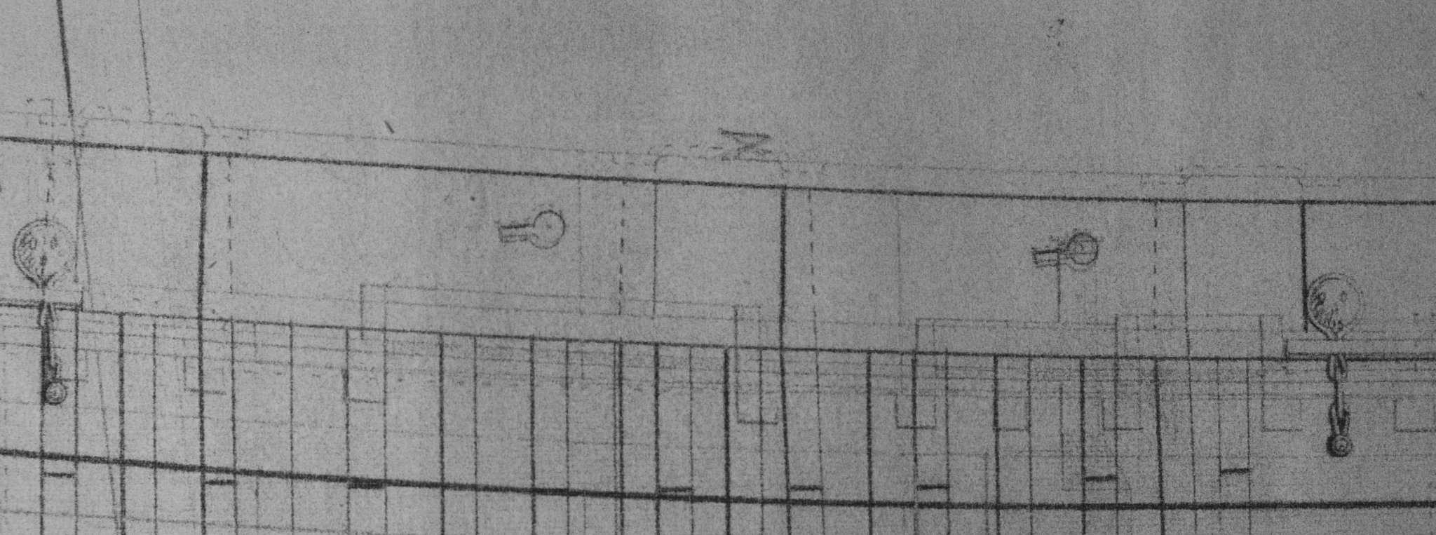
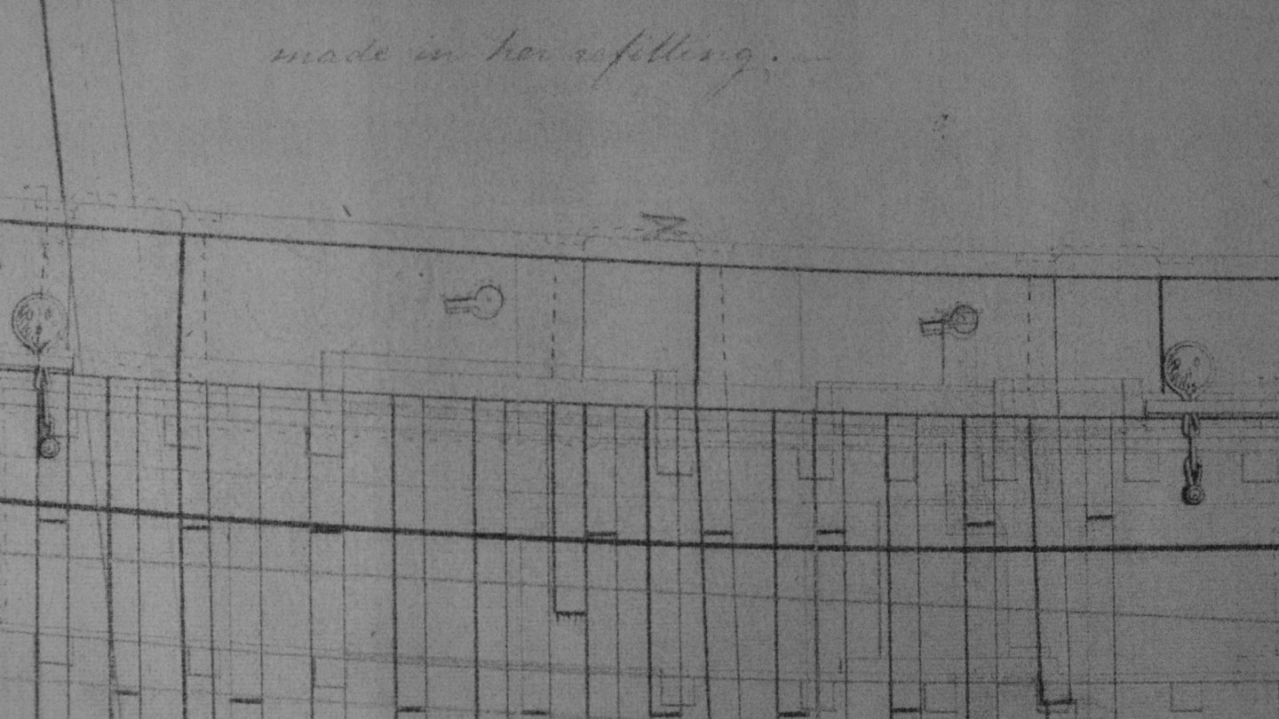
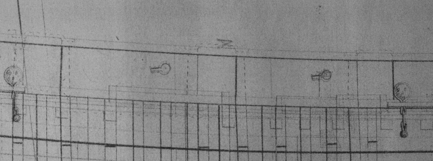
I have built the bulwarks on my 1/64 model of HMS Whiting (Caldercraft Ballahoo) and am now gazing at the Admiralty drawings and pondering the details of the gunwale. Here is an extract from ZAZ6116 at the National Maritime Museum. There are three gun ports in this small section and all show a dotted-line feature that appears to sit on the gunwale where it goes over a port. The ends of the feature are sunk into the top of the gunwale to either side of the gun port. The other gun ports do not carry this extra piece. My best guess is that the feature is an iron bracket to strengthen the bulwark around the gun ports which actually could take a gun. Does anyone have another suggestion? The gunwales must have been made from planks that were joined end to end. I expect that there was a scarph of some description but have not found any descriptions of what it looked like in 1800. There are some websites that show a simple, angled joint and even give a 1:7 proportion of width to length, but these are for repairs to modern canoes. The margin planks on the deck had a complicated scarph and I wonder if the gunwale had something similar. Ideas anyone? The Admiralty drawings do not show any timberheads though there is a feature at the extreme bow which could be one or a pair. The Caldercraft kit supplies timberheads and has holes in their precut gunwales for them but I suspect that this is a mistake. Any advice on this? George
-
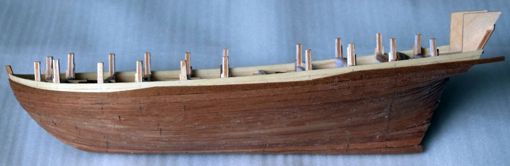
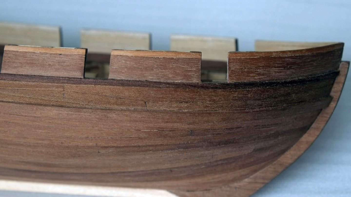
Progress with the hull in the last couple of weeks. I finished the sanding, and the stem and stern posts and keel, and the wales. The upper wale is in 2x2mm walnut and sits on the top edge of the top-and-butt planking. It needs the uprights for the bulwarks to hold it in place. The photo below shows the top-and-butt now that the wood has aged by a few days. The keel is in limewood because I had some of the right size and it will be covered by the copper plates later. The bulwarks are now growing. I cut away the sticky-up bits on the kit bulkheads, finished my curved uprights and put a short piece of walnut between each pair to give the lower edge of the gun ports. Each 'H' in walnut on the photo is the beginnings of a gun port. The outer face of the bulwarks has now been planked with two rows of 4x1mm walnut between the gun ports. They need to grow another 2mm taller and I will wait for the inner layer to catch up and then place a 3x2mm wide plank to complete both the inner and outer bulwark planking. Gunwale to go on top of that. More work to do on the bulwarks and then I will get some photos here. I have another thread going about chase gun ports in the transom, and the ship's name. Here is the link if you want to see that discussion. https://modelshipworld.com/topic/27728-chase-gun-port-lids/?tab=comments#comment-796589 Off to get my Covid vaccination shortly. Hopefully some normality will return eventually. George


-
I have had a look through some of my books and there is a mixed message about chase ports and names. Surely no-one expected clarity? Brian Lavery 'Nelsons Navy'. p65. A line of text states 'The names of the ships were painted on the counter of the stern.' This might only apply to proper ships, and the counter on a schooner like Whiting was around 50deg from vertical so it would be unreadable. The same page has a picture of a model of HMS Boyne 1790 at the Science Museum, London. There is a lot of carving on display, no name, and the gun port lids on the deck below the cabins are hanging vertically from the bottom edge of the ports. Brian Lavery 'Nelsons Navy'. p144. A painting of Hermione being cut out shows her name clearly. Two cannon are visible at the stern below the cabin but I cannot make out the port lids. Brian Lavery 'Nelsons Navy'. p257. A painting of Vanguard at the battle of the Nile shows her name, but again this is on a proper ship. Peter Goodwin 'Naval cutter Alert'. pp33-34. A contemporary model of Hawke shows her name on the transom. Peter Goodwin 'Naval cutter Alert'. pp42-43. A model of a cutter of around 1785 has no name on the stern. The stern ports are open for the cannons and it looks like the lids are hinged at the top and open outwards. Marquardt 'Global Schooner'. Nothing relevant. Chapelle 'Baltimore Clipper'. Nothing relevant. The case is unproven at the moment and any choice could be defended. Other sources of information beyond Admiralty drawings and contemporary paintings can provide valuable clues. I am currently deciphering the handwriting in Lieut. Roach's log book (he was on Whiting in 1806) and have found conclusive, revealing comments about her armament and coppering and sail plan. There is also one about her being painted but no detail about what was painted and in which colour. There might be something later about the stern chase ports and I can only hope that I find it (if it is there) before I put knife to wood on my model. Whiting gets several mentions in the Royal Bermuda Gazette in 1805 and they refer to her as the Whiten. This suggests that her name was given orally to the journalist and he did not see it painted on her stern, or perhaps he was not very good at his job and spelled the name wrong despite seeing it. Thanks for all your comments and advice. More please! George
-
Thanks again for more information. I did not know about the Admiralty orders concerning names on the stern and am pleased to learn something. Do all these models of cutters and schooners that have a prominent name on the stern perpetuate a mistaken assumption? There are plenty of conventions in model making and this is one which I had not questioned. Similarly, is it a convention to 'put wood in the hole' and have a solid transom, instead of leaving the ports open? I shall look through the pictures I have to try to find examples from contemporary paintings or models. Druxey: The transom on Whiting is 30deg from the frames, so about 35deg from vertical when she is afloat. The name would be readable I think though the lettering would be foreshortened. Good point. George
-
Thanks for your suggestions, Mark and Charles. No lids is one answer but it would leave me with a problem about where to put the ship's name: if the transom has two big holes in it then writing 'Whiting' gets difficult... Most pictures of smaller vessels have the name across the transom even though there is provision for chase guns at the stern so some sort of lid appears to be standard practice. The mention of bucklers makes me think of them opening inwards with some rebates to support them in the closed position. It's plausible but I would like to see some evidence if this is what happened. No prize yet so please come up with more ideas! George
-
I am building HM Schooner Whiting in 1/64 using the Caldercraft Ballahoo and Admiralty drawings for Haddock and Cuckoo. The drawings show two square features on the transom which I take to be ports for chase guns. It would be cramped around the tiller to serve a gun or two but nevertheless the drawings are quite clear that the ports are there. What I do not know is how the ports were kept shut. There is no detail on the drawings. Discussions elsewhere about gun port lids are for a conventional broadside arrangement where the bulwark or side slopes inwards and lids that hinge up and out to open them are an obvious engineering solution. However, the transom slopes out and this approach of hinged at the top and opening outwards does not seem very practical: there would be a catch or sliding bolt at the bottom edge which carries half the weight of the lid when it is closed, and some arrangement to keep it open would also be needed. Two alternatives that I can think of are 1. Hinged at the top but opening inwards. Rebates around the frame would support the weight of the lid when it was closed. A catch at the bottom would have to stop a following wave from pushing the lid in. The open position for the lid would be up and over so it lies at 180deg from the closed position. 2. A loose lid that sits on a rebate when it is closed. The bottom edge is retained by an iron or wood stop, and the top is held closed by a sliding bolt or wedge. To open the port the lid would be lifted out by two seamen. Does anyone know what method was actually used? It would apply not just for a schooner but for all smaller vessels such a cutters and sloops. Failing that I would gladly listen to an informed opinion. George
-
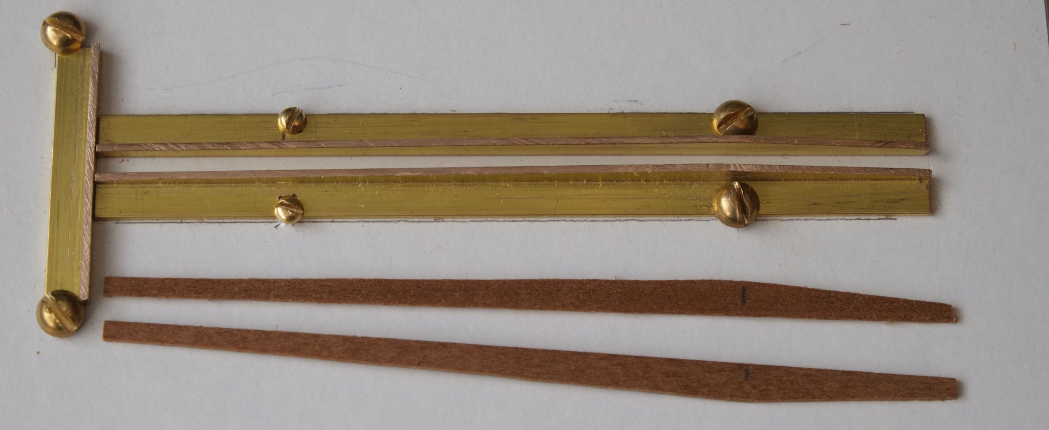
Top-and-butt planks. It took me about 5 hours to make a jig out of brass angle section for cutting these planks and then 10 minutes to cut the 12 planks that I needed for Whiting. It could have been quicker to cut each plank individually but I suspect that the fettling needed to make them fit would have been time consuming. As it is, I have a jig for the next ship... The wales have two rows of these planks. The photo here has had the lower row fitted and shows the rising and falling line that will match with the next row. Photos with both rows fitted do not show the planks clearly; a later layer of varnish might highlight the joins between them. I have now sanded the hull and glued on the stem post at the bow. Current job is to glue some uprights to the inside face of the hull. These will be the sides of the gun ports and also support the bulwarks. Two issues are troubling me at the moment. 1. Timberheads. The kit provides timberheads to fix to the gunwale but the Admiralty drawings do not show them, neither does Petersson's rigging book, neither do various other drawings. Is this a Caldercraft mistake, or do Admiralty drawings assume that the shipwright will add timberheads as part of normal practice? My inclination at the moment is to leave off the timberheads. 2. Bowsprit mounting. I had assumed that the bowsprit was held down at the stem post with an iron ring, as for cutters. However, a drawing in Marquardt's Global Schooner shows gammoning that loops over the bowsprit. The lower turns of the gammoning go through a ring that attaches to the stem post. Does anyone have information about this? George