georgeband
-
Posts
307 -
Joined
-
Last visited
Content Type
Profiles
Forums
Gallery
Events
Everything posted by georgeband
-
 Ollie, Thank you for your kind words about my book. There is another thread where it was discussed previously though it has slipped down the listings now and is not so easy to find. George
- 2 replies
-
- 6
-

-
- caldercraft
- Sherbourne
- (and 1 more)
-
Not much progress since I almost finished the 6lb cannons. Christmas with grandchildren (and their parents) took priority over model making. For the next task I will probably put small cleats on top of the gunwale to hold the falls from the gun runout tackles. However, I will be away from modelling for the next few months so there will be nothing to report for a while. George
-
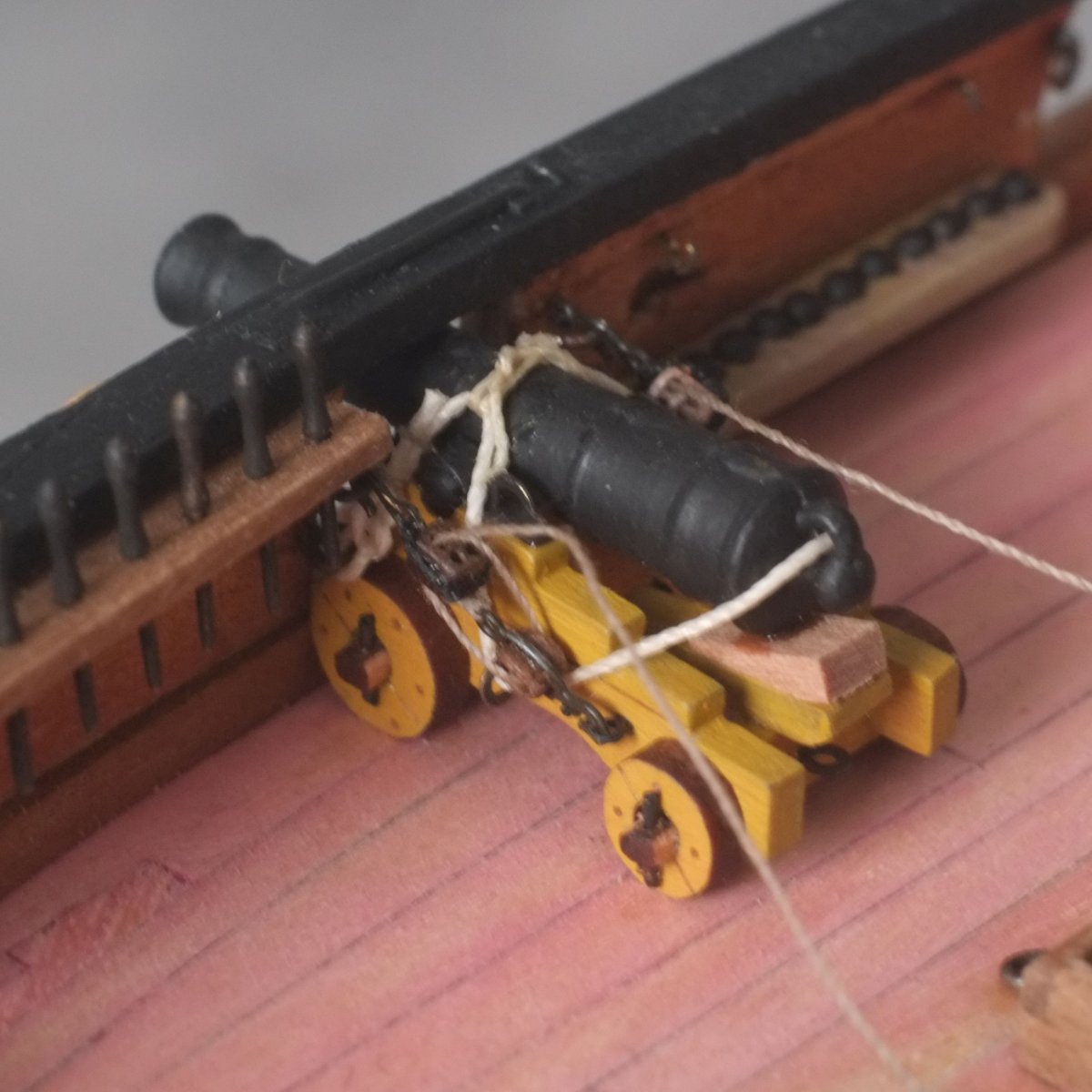
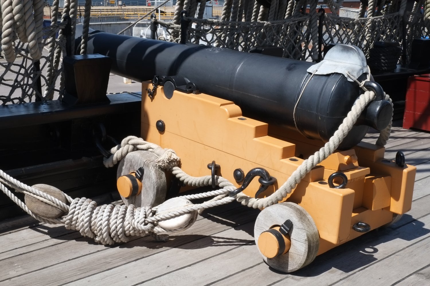
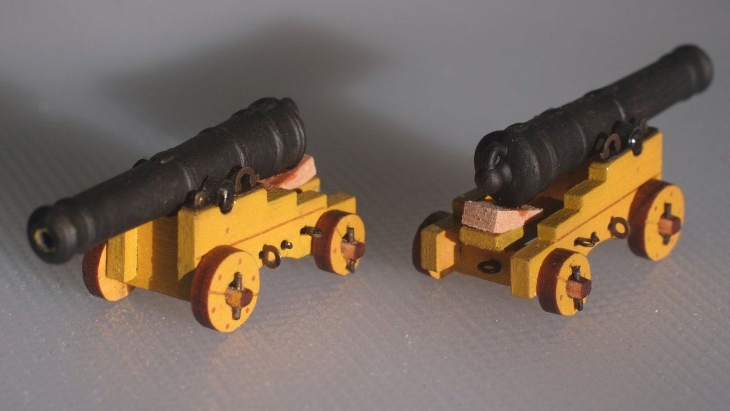
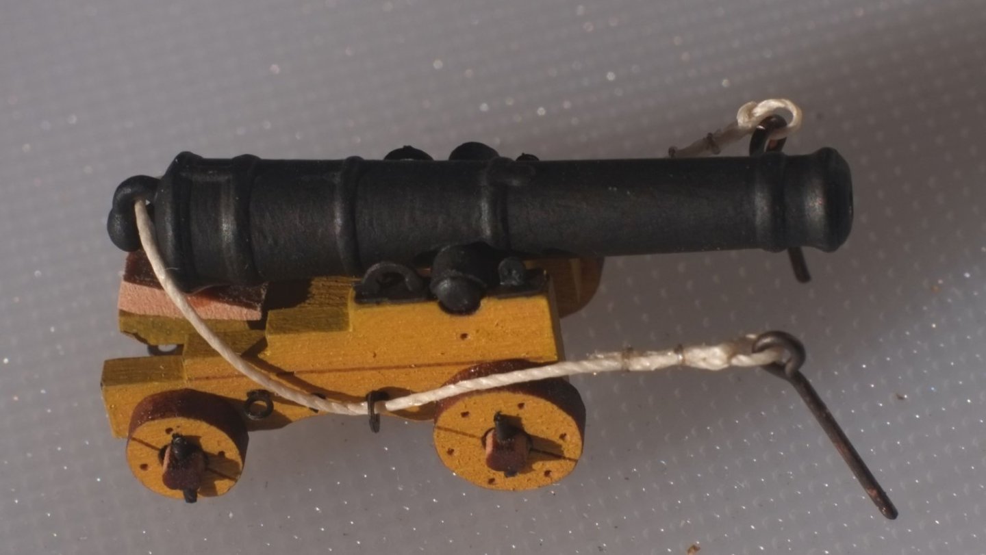
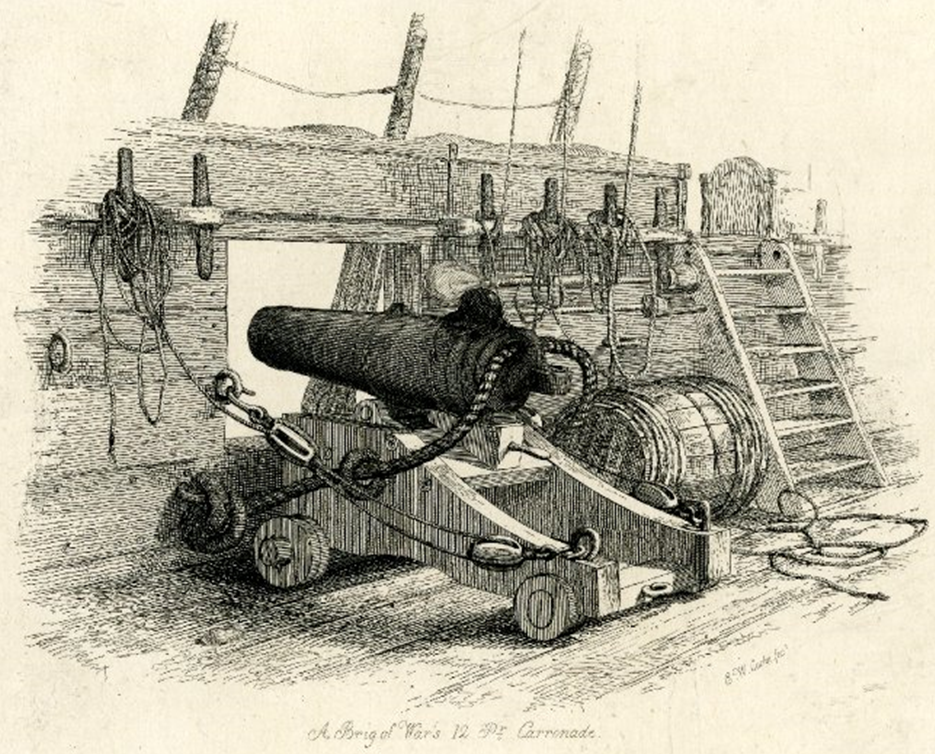
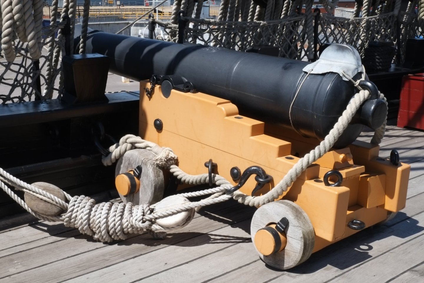
6lb cannons Whiting carried two 6lb cannons and two 12lb carronades and I assembled the cannons first. I used the Vanguard Models kit as the basis for the carriage. It is nicely laser cut from pearwood with sharp edges and corners and a useful fret of etched brass parts. Some of the brass parts are tiny (look at the caps for the trunnions) but are still oversize. I was lucky not to lose any during assembly. Note to Chris if he sees this page: Please can you put in five of each etched brass part so that there are spares for when the bit you are working on pings onto the floor? The quoin is not included in the kit but is simple enough to make. I painted the carriages yellow ochre and left the running surfaces of the trucks (wheels) in the scorched finish from the laser cutting. The barrels in the Vanguard Models kit are very nicely 3D printed representations of Blomefield guns. Unfortunately for me they are 8 foot long in scale and cannot fit on Whiting; loading would be near impossible and their recoil would demolish the hatch over the fore ladderway when they were fired. I found replacements in the Amati range 'Part no. 4165/30 1:100 Scale Victory Cannons 30mm' which are the right 6 foot size for the model. They needed some gentle filing to remove a small step at the mould join and then a coat of black paint. The breeching rope is from Caldercraft '0.5mm' natural thread which is closer to 0.4mm. I tied one end through an eye with an overhand knot and seized the joint. The thread was then fed through eyes on the carriage and cannon and tied to another eye so that at full extension the mouth of the barrel would be a millimetre or two inside the bulwarks. Pushing a cocktail stick into the eye gives something to hold during tying and stops the thread from slipping. In the photo below the eyes still have their long tails which will be cut short before gluing into the prepared holes in the bulwarks. Fitting the cannons into the hull needed some fine juggling and I unhooked the gun tools to allow better access. I glued (CA) the foremost breeching rope eye first, somehow getting it in behind the belaying pins, and then glued (PVA) the trucks to the deck with the gun run out. The other breeching rope eye was easier to tuck into its hole and when it was secure I adjusted the rope so that there were equal lengths on both sides. I used some fine Amati thread to lash the left and right sides of the breeching rope together over the barrel. The gun runout tackles have a single block hooked to the carriage and a double block hooked to the bulwark. I used 2mm blocks from HiS models in Czechia which are wonderful examples of CNC work. The etched brass 'clamps' from HiS were useful for the single blocks because they provide a hook at one end and an eye at the other. Those for the double blocks were too loose and I could not use them, and resorted instead to black thread as a strap around the block together with a HiS etched hook. The rope is Gutermann polyester in a pale brown shade (col. 724) which is 0.20mm diameter and I used 10cm lengths. Hooking the tackles in place was easier than I expected. Now I need advice about what to do with the falls from the gun runout tackles. There is about 8cm / 3 inches in scale (15 feet actual) which has to go somewhere and I suspect it was at the captain's whim. Here is one example from a well known picture by EW Cooke. It looks scruffy but might be typical. And here is a much smarter one from HMS Victory which uses sheepshanks and a lot of coiling to lash it all together. There is not enough room on Whiting to accommodate this style. (Note that the breeching rope is left hand lay.) I refuse to make round floor mats by laying the rope in a spiral on deck. My thoughts at the moment are to add a hook or a pin somewhere on the gunwale and loop the coiled rope over that. Does anyone have evidence or other ideas? George

-
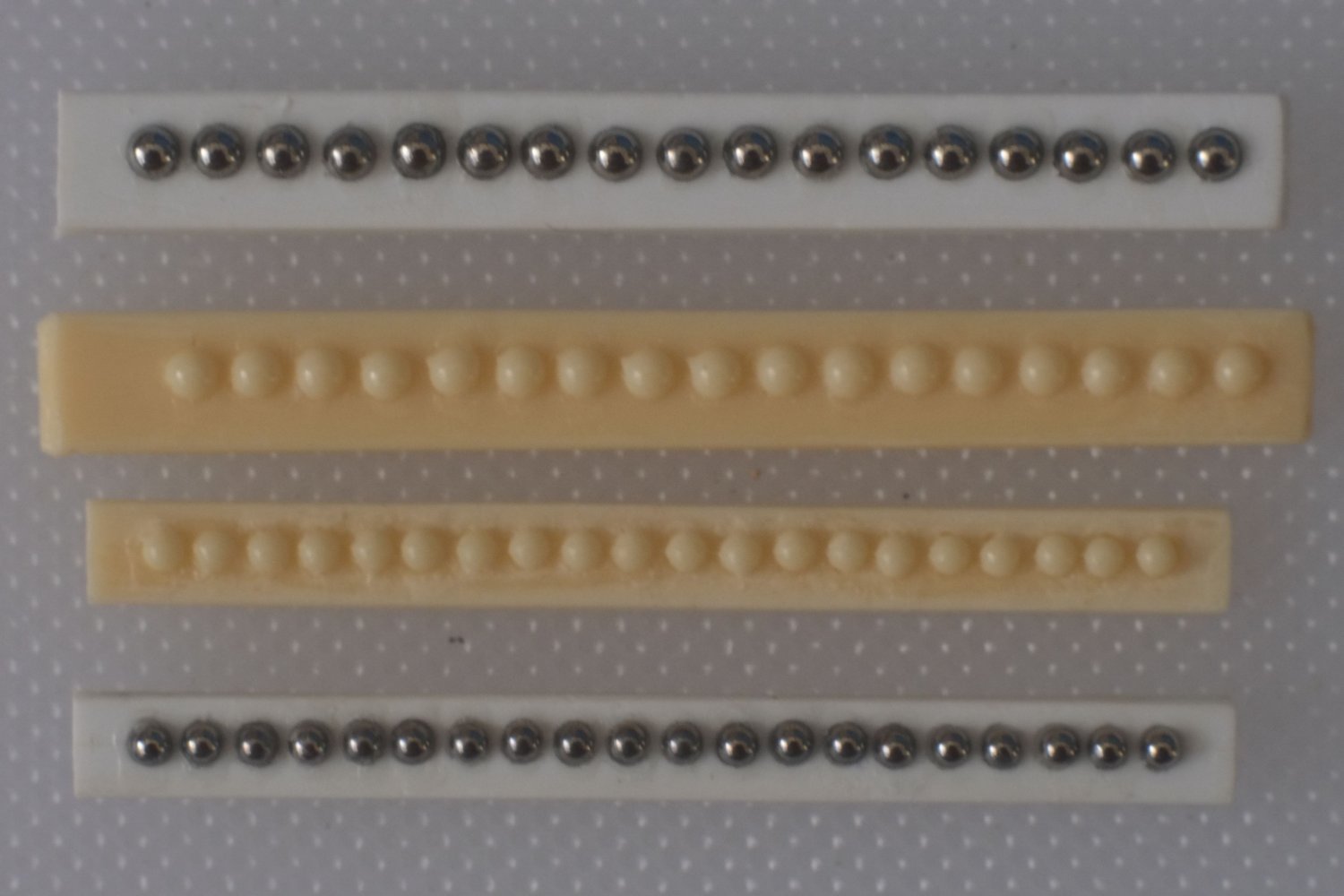
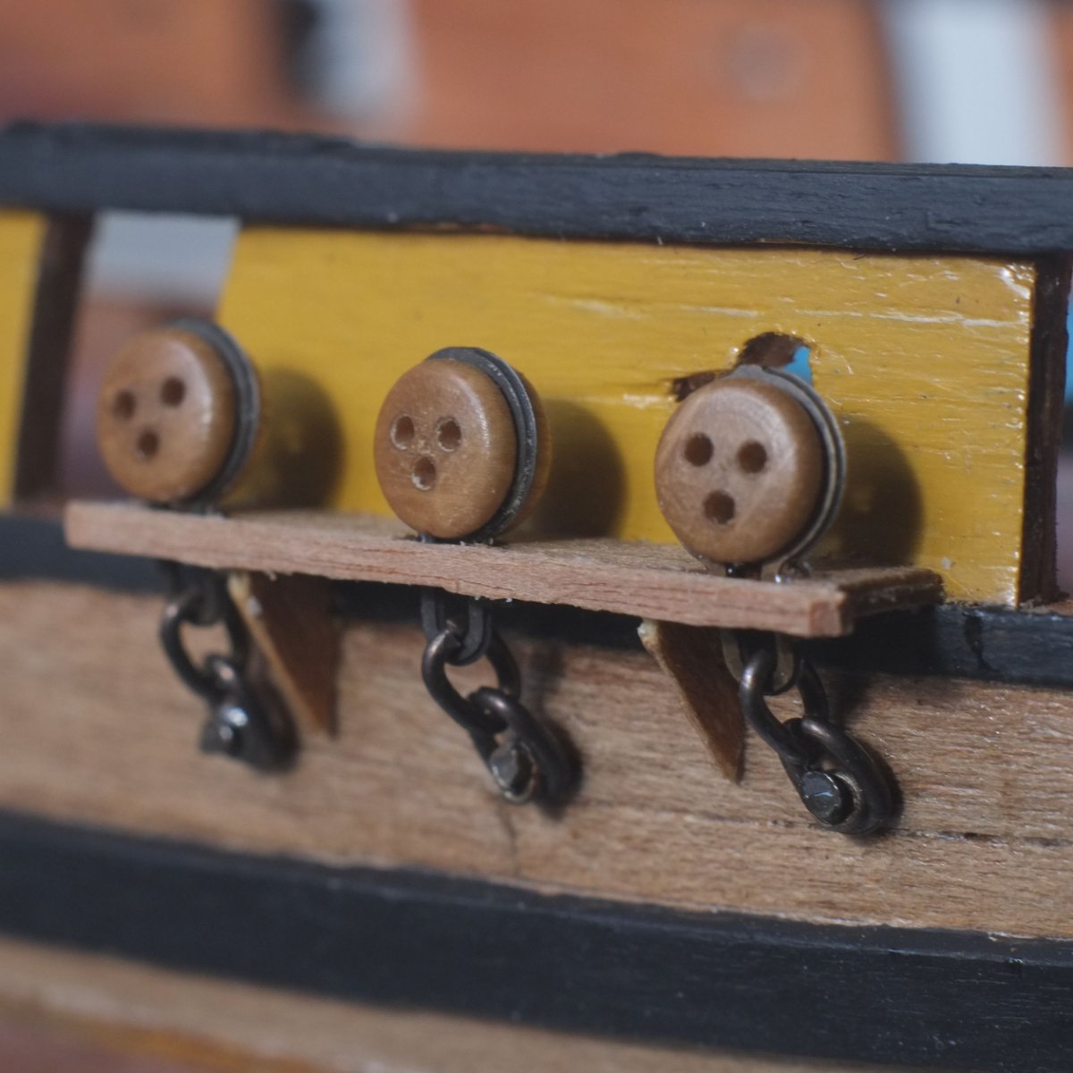
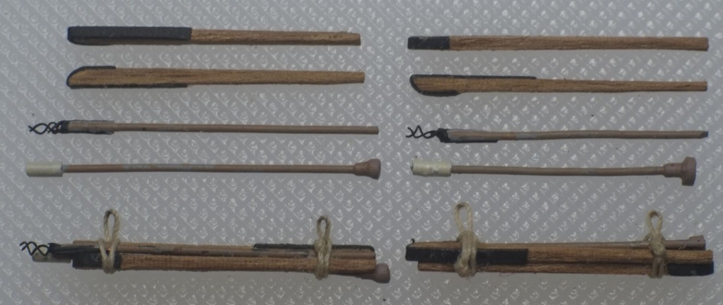
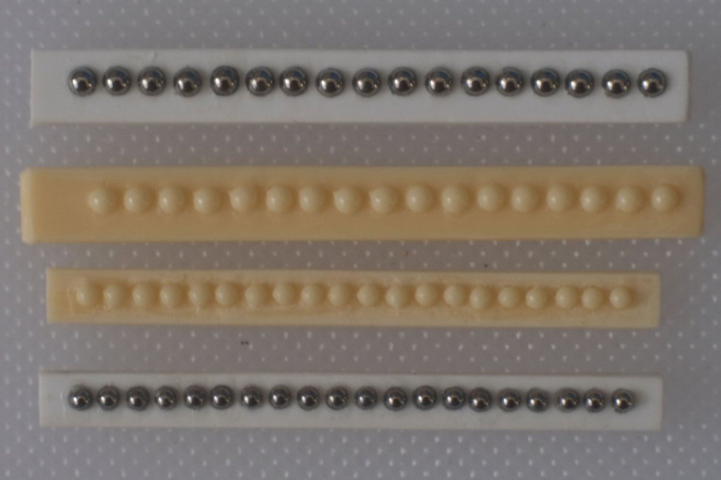
Gun tools and shot racks I have made the gun tools now. It was an exercise in assembly of fiddly little bits and then painting them. The rammer and sponge are from wire with plastic insulation and tubes pushed over the ends. The worm is also wire for the shaft and very thin wire for the double helix. The handspikes are cut from 1mm thick walnut and given a layer of black paper to show the iron cladding. The longer tools in the photo are for the 6lb cannons, the shorter are for the 12lb carronade and I tied them into bundles so that they can hang on the bulwarks. Tying the thread loops around the bundles was a very slow process because of having to wait for PVA glue to harden. I am surprised at how few models that have guns on an open deck actually show the gun tools. Were they stored somewhere else? Below decks on HMS Victory they are suspended from the ceiling. The shot racks started off as plastic card and ball bearings. One strip of card had holes drilled through it and a second strip was glued below it to create blind holes with uniform depth. The ball bearings were then glued in. I used 1.5mm balls for the 6lb shot and they are a close match for size. The 12lb shot should be 1.75mm diameter and I had the choice of 1.5mm or 2.0mm, and chose 2.0mm which exaggerates the difference from the 6lb balls. I used these shot racks as masters to make silicone moulds and then cast replicas in polyurethane resin. I can make more now quite quickly for future models! Cutting to size, sanding the width and thickness and a paint job finish the racks. The photo below shows the 1.5mm balls; the whole rack is 25mm long (1 inch for those who think in Imperial) so please do not be too critical of shaky boundaries between black balls and the brown rack. I glued the racks and the bundles of gun tools to the bulwarks above the waterway planks. (One loop of thread has slipped off its hook and the black paint on the worm has to be touched up.) George
-
Gregory, Darcy Lever writes a lot about raising and lowering the studding sails depending on changes in the wind direction. He does not say much about wind strength. I have been transcribing the log book of John Roach who was sub-lieutenant on HM schooner Whiting and he set the studding sails in strong winds to get more speed. (He also lost some sails.) He also sometimes set them on the windward side only, which I believe was common when the wind was from the side. Luis, Henry, I agree with you about a model looking splendid when a lot of sails are set. My intention with Whiting is to display the windward side so that the rigging is still visible. The windward studding sail will be set but not the leeward one. (Whiting carried studding sails only on the fore topmast. She did also have a ringtail sail which is the equivalent of a studding sail on the main (aft) gaff sail. The clippers might have had a ringtail sail at the stern too.) George
-
Luis, This is a good question and the answer can change depending on if the wind is from behind or from one side. I agree with Henry that the most common answer is to have the stunsail behind the square sail on the windward side. On the lee side the stunsail is forward of the square sail. Sometimes only the windward side is set and the leeward stunsail is not carried. If the wind is from behind then both stunsails would be carried. If you look in Darcy Lever's book 'The Young Sea Officer's Sheet Anchor' there is a lot of discussion about studding sails on page 65 and pages 80-82. The book is not the easiest to read and packs a lot of information into a few words but it is a contemporary source. George
-
sail plan for Ballahoo (Fish class) topsail schooner
georgeband replied to georgeband's topic in Masting, rigging and sails
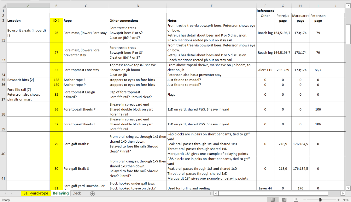
Phil, Thanks for your comments. Petersson shows a ring with belaying pins on the main mast and I am copying this approach for my fore mast. Eight pins would have a spacing of about 3mm which gives enough space for rope coils to hang from them. For the main mast there are not so many belaying points (on Whiting) and I will probably put cleats there if only to make it different from the fore mast. Petersson's drawing of the fore mast has a curious arrangement of pins that sit horizontally in a vertical rack. I cannot understand how this would work because the rope coils from the higher pins would tangle with those below them. It looks wrong to me but I do not have practical experience of sailing and rely on engineering 'what-if' judgement. Any ideas? George- 22 replies
-
- 2
-
-
- caldercraft
- jotika
- (and 4 more)
-
sail plan for Ballahoo (Fish class) topsail schooner
georgeband replied to georgeband's topic in Masting, rigging and sails
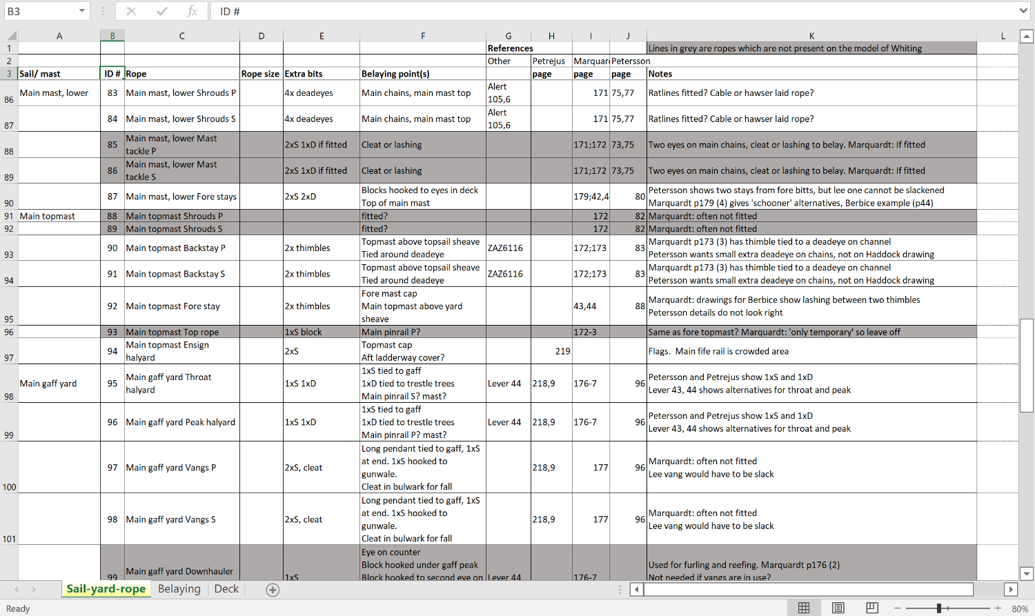
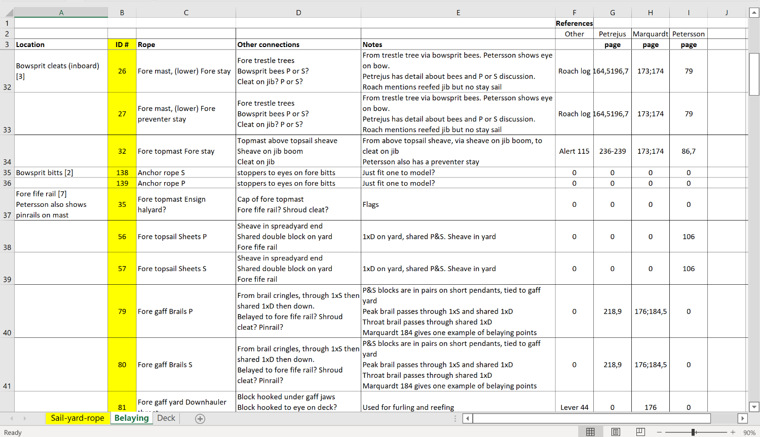
The deck belaying plan has evolved and reached a state where I am prepared to use it for my model. There were quite a few judgement calls along the way and some might have chosen a different path. There is a very slim chance that someone documented it 200 years ago but realistically I think we will never know what was done on one vessel at one period in her history. The Excel file below shows the steps I went through. First was to make a comprehensive list of ropes. After that the list expanded and was grouped to show which ropes ended or passed through a particular location. Then came the tricky part of assigning belaying points. The spreadsheet does not show the arrangements at mast heads or on the yards; I do not need them yet and they can wait for another year... sail rigging plan.xlsx George
- 22 replies
-
- 3
-
-
- caldercraft
- jotika
- (and 4 more)
-
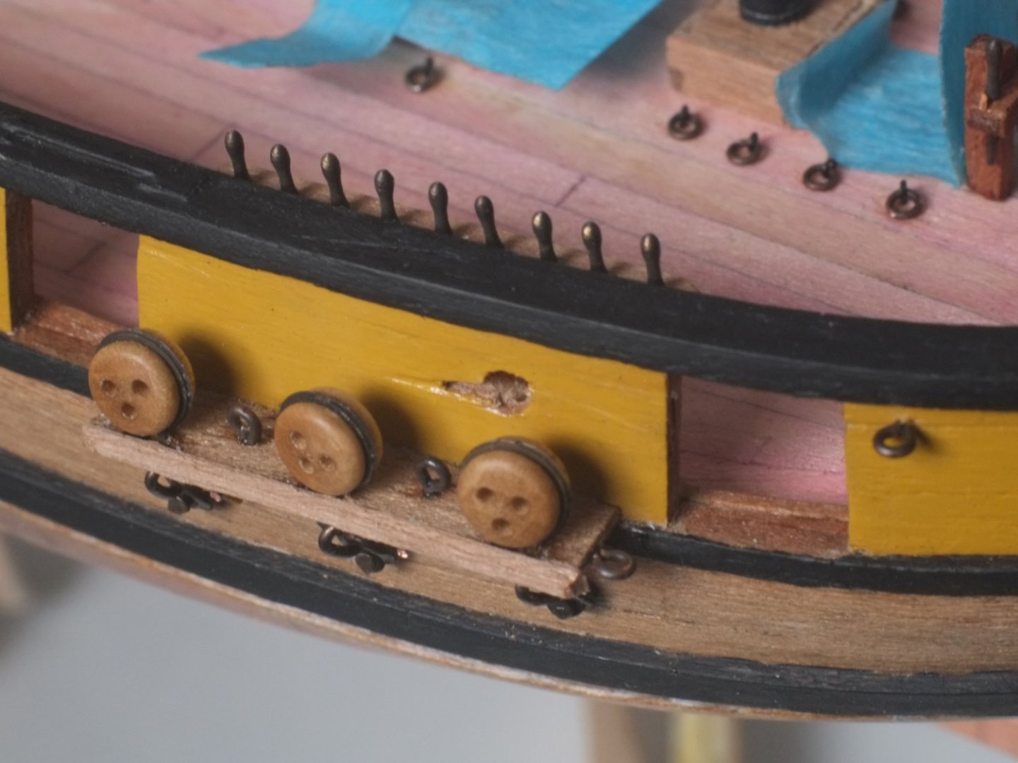
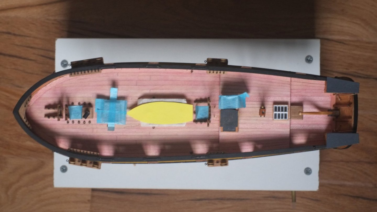
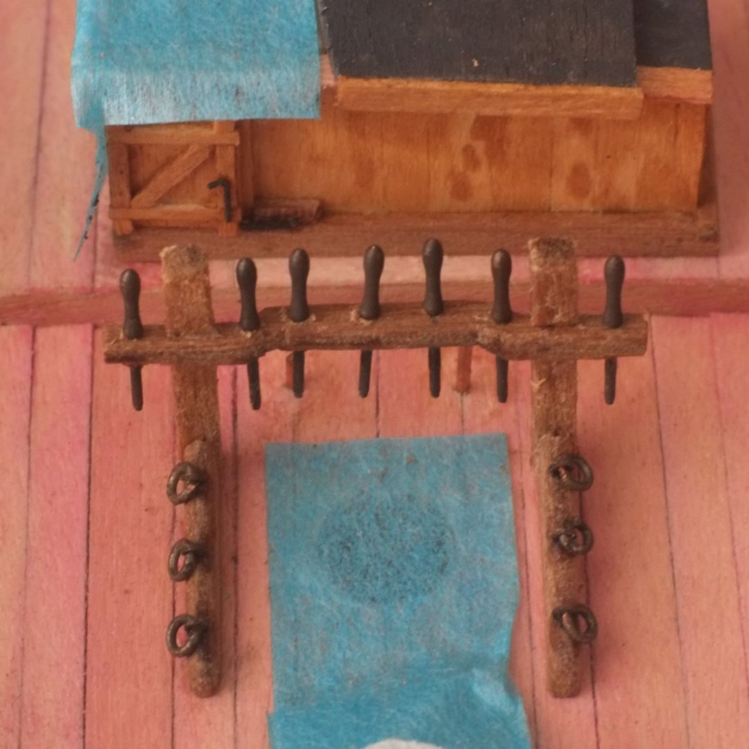
Eyes almost everywhere My belaying plan has reached a level where I feel I can justify my decisions, though I am sure that a competent sailor would disagree about some of the placements. The belaying pins went in a month ago and I have now added a lot of eyes to the deck and the bulwarks. Some more are yet to come but the model making will be less stressful if I leave them until after their ropes have been tied to them. From left to right on the photo below: A hook in the bulwark for gun tools (below it is the sweep port and below that the scuttle in the waterway) An eye in the bulwark for the gun tackle A hole below the eye for another eye later. I will tie the breeching rope to the eye before gluing it in Peeking over the left gunport is an eye for the other gun tackle Visible through the right gunport is an eye on the fore channel for the staysail sheet Extreme right there is an eye on the outside and its tail has been clinched over inside the bulwark The next photo is the same area from the outside, starboard this time. Top centre is an eye for the gun training tackle Top right are four eyes in the deck (five on port side) for yard lifts, gaff tack and main mast fore stay To the right on the bulwark is an eye for the bowsprit shroud At the fore (right) end of the channel is the eye for the staysail sheet Two eyes on top of the channel are for the mast tackle The tops of the belaying pins have worn a little and will get a touch of paint later And here is a general view of the deck. I have taped over all holes to stop rubbish from falling in. The pumps are taken out for the moment and locating pins sit waiting for their return. The yellow boat outline is where the cutter is stored and reminds me how cramped it is on deck. I am now working on the gun tools, and while a rammer, sponge and crowbar are easy enough to scratch build the worms are delicate and tricksy. There are also nine cleats to prepare. George
-
I have been researching HMS Whiting in obsessive detail for a model of the schooner that I am building. One branch of the research took me off on a tangent which gives a flavour of the war of 1812 from the perspective of a small trading vessel. False colours abound and the boundary between privateering and piracy is definitely crossed. Spoiler alert: at the end the lawyers win. The 1805 Club accepted my paper and published it in their magazine, the Kedge Anchor, earlier this year. I have attached a pdf extract which is only two pages so a quick read. Enjoy! If you don't know about the 1805 Club then have a look on Google. George KA 57 Bandurek.pdf
- 1 reply
-
- 6
-
-
Seats of Ease
georgeband replied to stuglo's topic in Discussion for a Ship's Deck Furniture, Guns, boats and other Fittings
On HMS Victory there were four seats of ease at the heads to serve the needs of about 800 men. (The officers had their own arrangements.) If all the seats are used throughout the day and night that gives just over seven minutes on average for a seaman to finish his business. Given that many of them would be constipated because of the diet, and in rough weather only the two leeward seats would be in use, it is obvious that they would find alternatives such as the bilge or a bucket or leaning out at the channels. Photo below shows the seats on Victory, port side. On smaller vessels the Admiralty drawings often show a cupboard-like structure at the stern to port, tucked in the corner between the transom and the bulwark. It is labelled as the 'necessary' which was a common euphemism at the time. Occasionally the seat was left open to the air and any chance of modesty disappeared. The Simmons thesis, if I remember correctly, also mentions 'pissdales' which are holes through the bulwarks that the sailors could use to relieve themselves without having to open the gun ports. I suspect that there would also be a bucket nearby with strict orders, enforced by the crew, to empty it after you had used it. George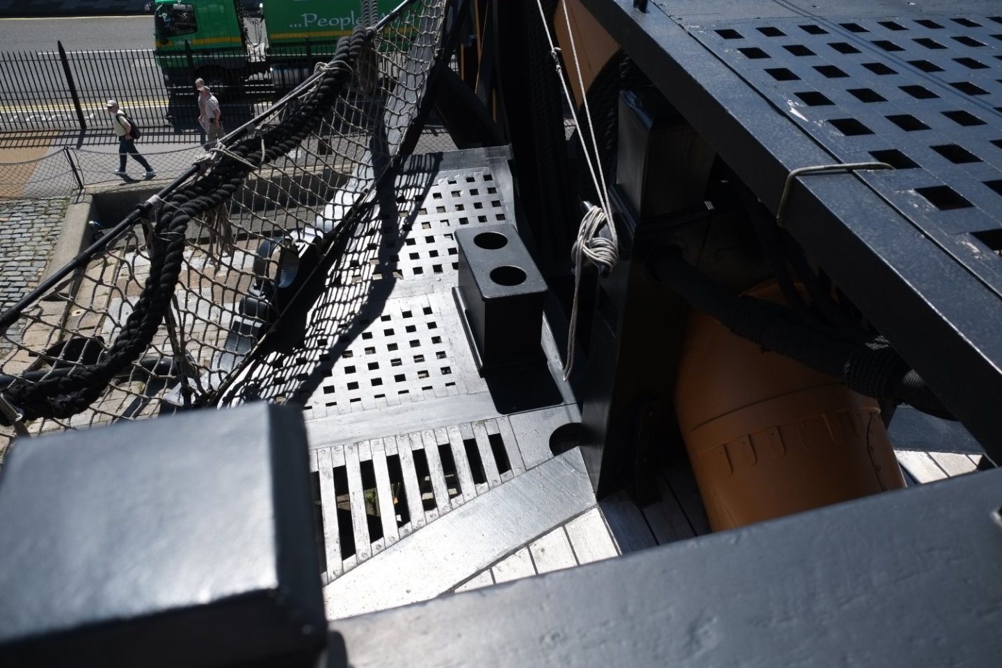
-
sail plan for Ballahoo (Fish class) topsail schooner
georgeband replied to georgeband's topic in Masting, rigging and sails
Thank you all for your likes and comments. Phil: I am going through the same thoughts about pinrails and cleats on the masts (Petersson shows two examples) and shroud cleats. I have expanded the second tab to show these additional belaying positions explicitly even though no ropes are assigned to them, yet. Wefalck: Whiting had a crew of 20 so there were enough men and boys to do the work. I have made the fore topgallant flying so there are only a few ropes to raise and handle it. The third tab on the spreadsheet has expanded now. I show which ropes go to which belaying point using coloured symbols on the deck plan. Some on the mast pins or shroud cleats have not been assigned. I have not attempted to put the ropes in order at their belaying point for the moment. There are, for example, seven ropes belaying at the fore, port pinrail in some undefined order. It is enough to let me continue adding the deck furniture. sail rigging plan.xlsx Questions and comments always welcome, that's what lets me improve. George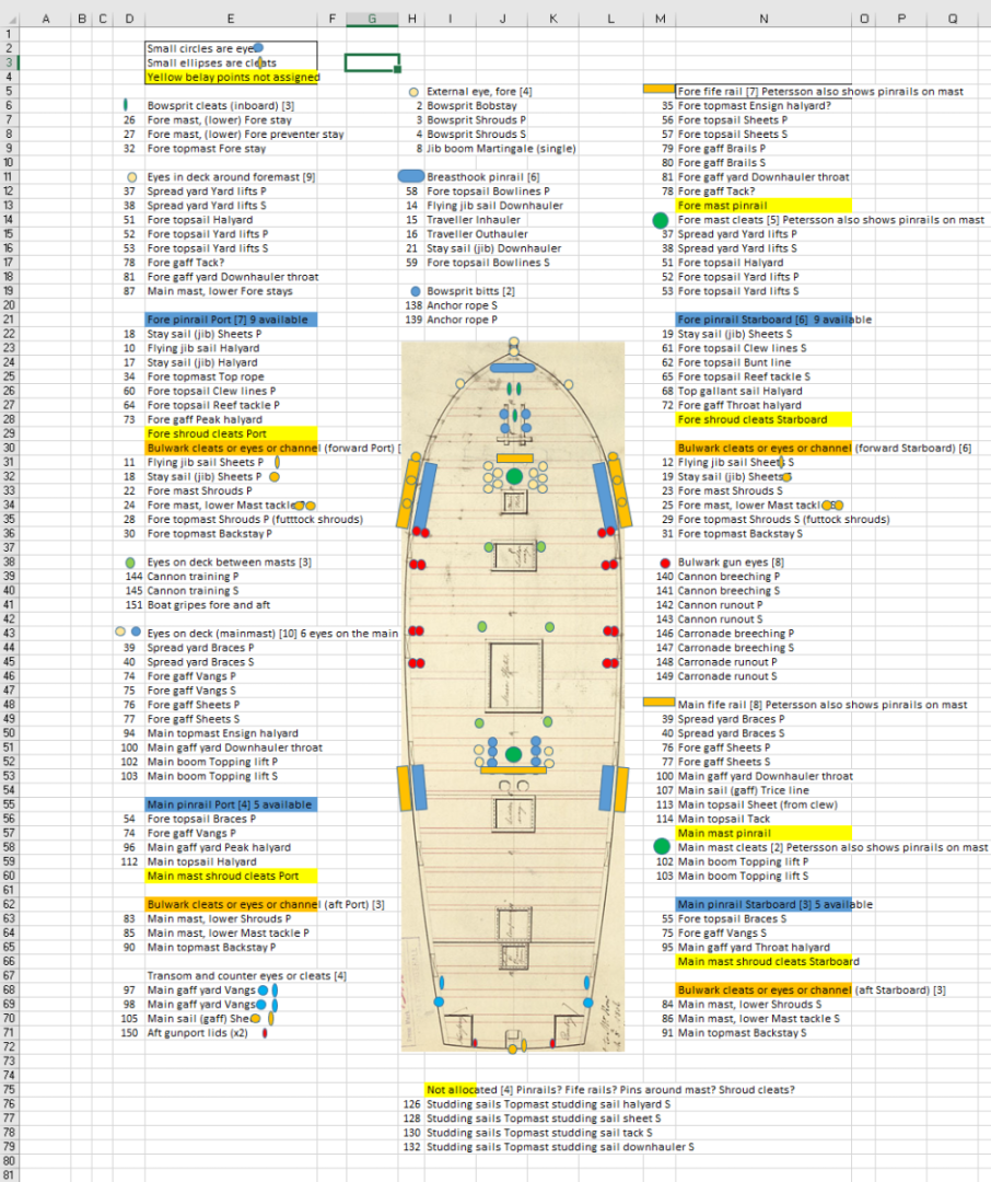
- 22 replies
-
- 4
-
-
- caldercraft
- jotika
- (and 4 more)
-
Thank you for your comment, Tony. I keep wanting to do some 'proper modelling' but find that my research is inadequate and I need to find out more, sift and sort it, shuffle it around and finally turn the data into useful information. I enjoy doing it but it is time consuming. I have added my current work on the belaying plan to another thread so it does not get in the way of the model build log. George
-
sail plan for Ballahoo (Fish class) topsail schooner
georgeband replied to georgeband's topic in Masting, rigging and sails
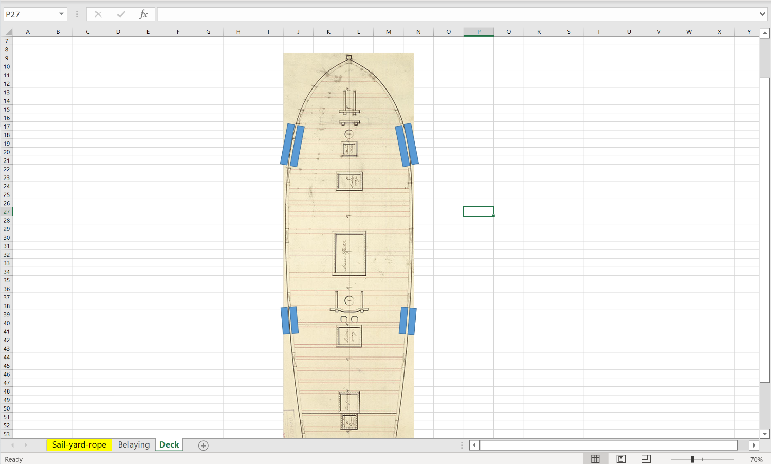
I have chosen the sail plan for my model of Whiting and it includes a lot of canvas. Working from fore to aft: Flying jibsail Jibsail riding on stay from foremast top to end of bowsprit Gaff fore sail (no boom) Square topsail on topmast Studding sail to starboard of the topsail Flying, square top gallant sail on the same topmast Gaff main sail with gaff and boom Gaff topsail on the main topmast Ringtail sail aft of the gaff mainsail I might well change my mind by the time I get to making these sails... The sizes of the masts and yards must wait a while because the more pressing task is to design the belaying plan for the deck. The belaying plans for schooners depend a lot on where and when and who used it and we do not have 'standard' plans as for ships. Marquardt frequently says that some rope or method might or might not have been used so there is a lot of judgement here. I will describe my method which might help others with this detailed operation. My approach has been to use an Excel spreadsheet to organise the information. So far it has three tabs (sheets) and the first (Sail-yard-rope) is a list of all the ropes that I could think of. I started at the tip of the jibboom and worked aft and up, adding more ropes in a fairly sensible order, until the list stopped growing. That's about 150 ropes for Whiting. The extract below shows the column headings. Sail/ mast. This is the title of a group of ropes. ID #. Reference number that links to the other tabs. Don't put these numbers in until you are confident that you have included all you want. Rope. Name of the rope(s). Mostly single ropes, but not always. For example, I used one line for a group of shrouds that went to the same mast from the same side of the schooner. Rope size. To be filled in later and I will use the traditional circumference in inches. Extra bits. Do I need to buy blocks (1xS = single block; 1xD = double block) or eyes or thimbles... Belaying points. This is summary description of the route that a rope follows. References. I used three main books for reference and they have their own columns where I put page numbers and drawing references. 'Other' has the less frequently used references. Notes. These explain to myself why I made a particular decision, because I will forget later. The lines with a grey background are for ropes which I will not include on my model. Two of them, the main mast tackles, 85 and 86, might yet become part of the plan. The second tab (Belaying) expands the 'belaying points' into one line for each location where the rope makes contact. They are grouped by the locations such as 'Bowsprit cleats' or 'Fore fife rail' which are in column A. I enter the ID # reference number in column B and then a =VLOOKUP formula fills in the other columns for me. One reference number will often appear in several groups if it has a complicated route. The extract below shows that I need three cleats on the bowsprit (I counted them manually, it's not some clever formula) and seven on the fore fife rail. The fife rail is not big enough for this so I have to look at putting pins or cleats on the mast as shown in Petersson's book. The third tab (Deck) is still somewhat embryonic. My intention is to arrange the ropes in their belaying groups so I know which to belay where. Petersson does this well in his book but unfortunately I cannot apply his plan directly to Whiting. I will use the same =VLOOKUP function to add details to this sheet. The reference numbers, ID #, are key. I guess that others have been through the same process and combined snippets of information into a coherent belaying plan. Any comments or suggestions? The spreadsheet is copied below if you want to play with it. sail rigging plan.xlsx George

- 22 replies
-
- 3
-
-
- caldercraft
- jotika
- (and 4 more)
-
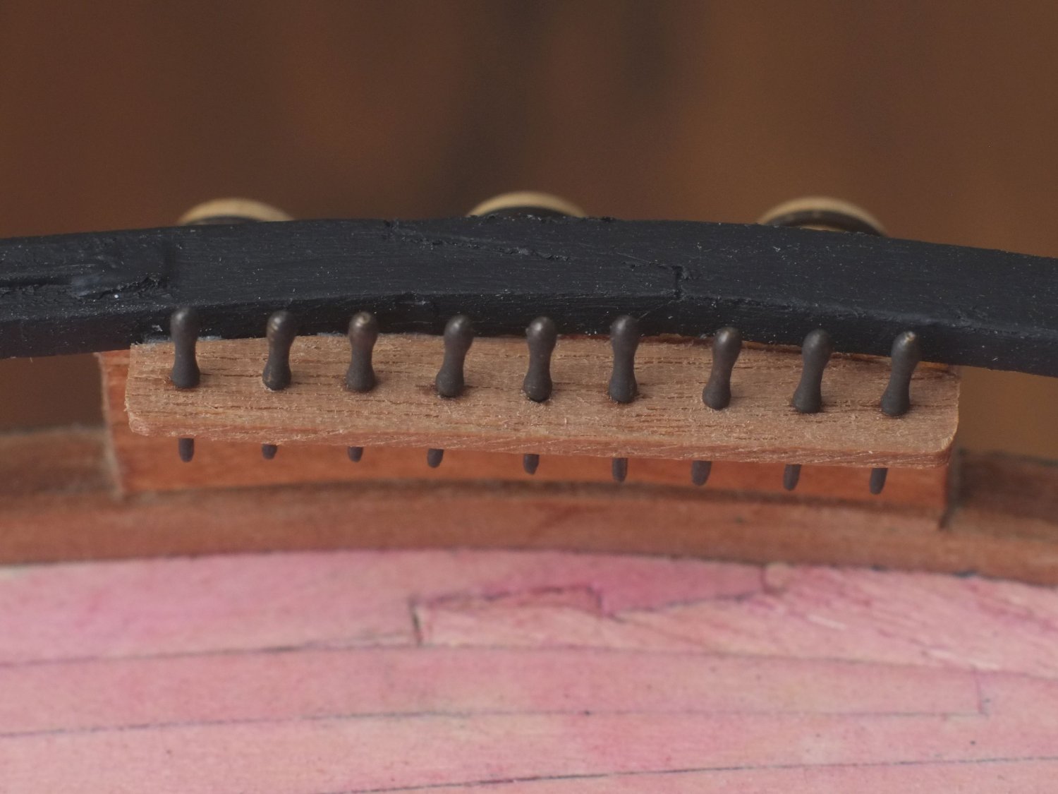
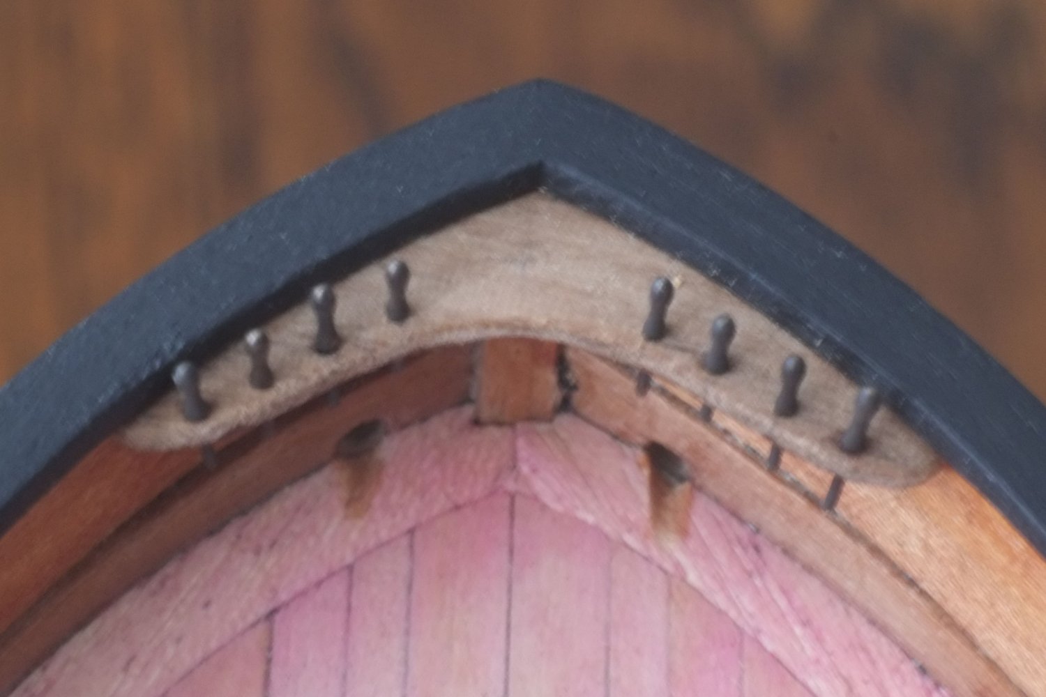
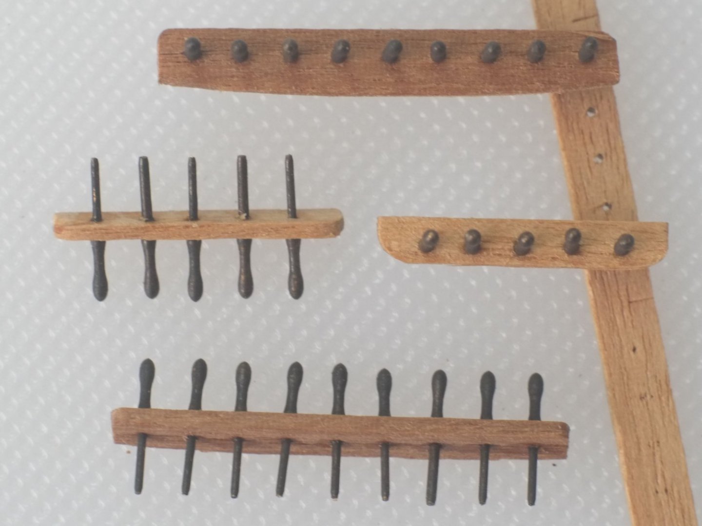
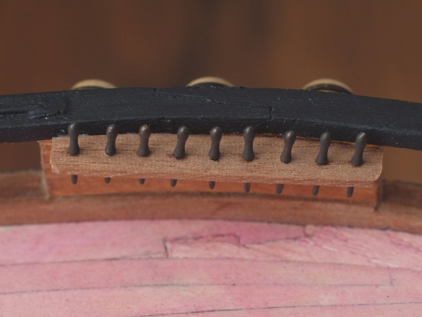
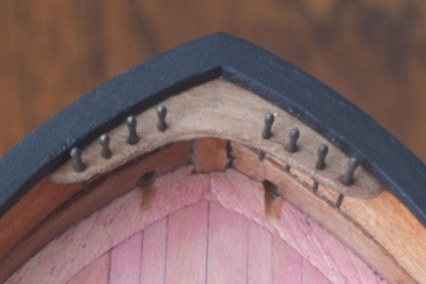
Pinrails and belaying pins These should have been a quick job, and they were once I had worked out how many pins I needed and where to put them. The time consuming task was to create the belaying plan for about 150 ropes. I will post about this a little later but for now here is what I did with scalpel and glue rather than Excel. I used brass belaying pins made by RB Models and blackened them with Carr's solution. They are much neater than the wooden clubs supplied in the kit. The pinrails are from 4x1mm walnut, cut to the same length as the channels for the deadeyes. The longer, fore rails have a curve on the outboard edge so they sit snuggly against the bulwark below the gunwale. I did consider putting a concave curve on the inboard edge but decided to keep it simple. The aft rails are straight and I reduced the width to about 3mm after drilling the holes for the pins. The holes are 3mm apart. I put the pins into the holes then fixed them from the underside with a tiny drop of CA. The completed assemblies were glued in place with wood glue. Having fixed the pinrails I glued pins into the breasthook and the fife rails. The breasthook has a purposeful look to it now and is calling for ropes to be belayed there. The aft pinrails and fife rail are in a very crowded part of the deck. I snapped out the pumps that I had previously glued in place because there was not enough room for a sailor to squeeze between the pinrail and the pump handle. I am considering shortening the handles (6 foot down to 5 foot) and inclining them forward. George
-
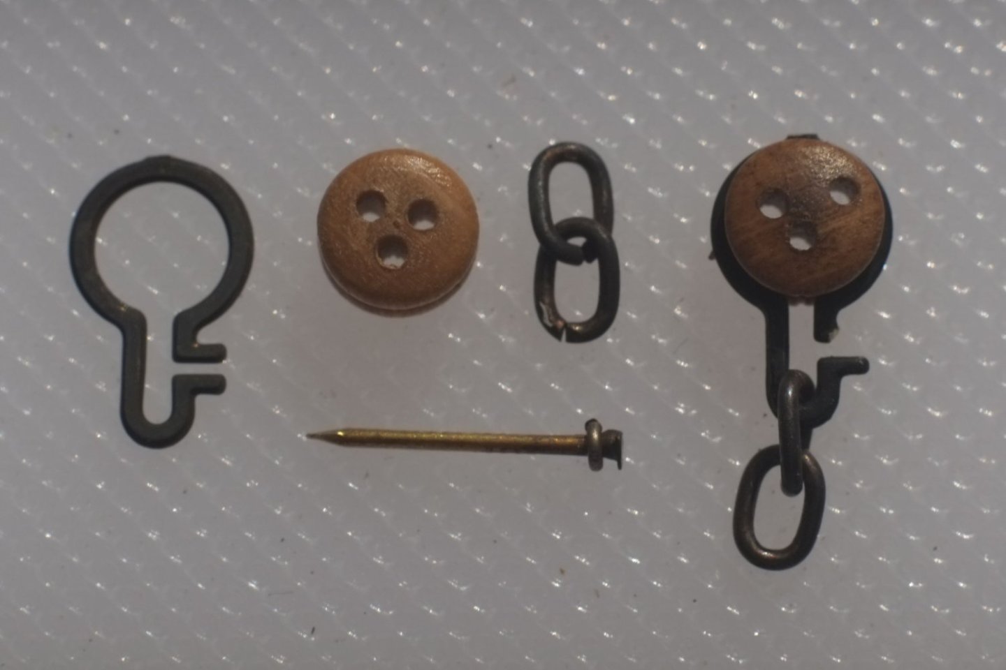
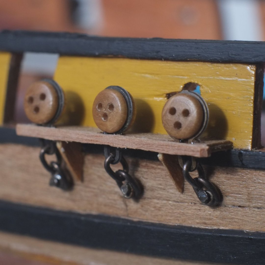
Summer is over and I am back in the modelling season for the next half year. I have been researching during the off-season and collecting and sorting information about masts and sail plans and rigging, of which more later. The practical work restarted last week and I continue with the various fittings on the deck and hull. Deadeyes, channels and chains The deadeyes come from the Ballahoo kit and some are distinctly cross eyed. I also had a few spares in the bits box and selected 20 that are acceptable. The best ones go on the 'presentation' side of the model and the slightly squinting ones on the side that will be facing the wall. The Haddock drawings show that the chains were two links of a chain and not the brass strap in the kit. I used a couple of links from Karaya chain that were the right size. I also used the etched brass frames from the kit to hold the deadeyes, with one sideways protrusion snipped off. The bolt to hold each chain to the hull side is a brass nail with a wire washer. Parts for the deadeyes, and a cross-eyed one assembled for practice The channels are cut from 5x1mm walnut and have triangular knees beneath them. The deadeye and chain assemblies were then glued in place with CA superglue. I used a temporary mast with a thread tied to it to indicate the angles of the shrouds and then marked the position of the bolt so that the chain was aligned with the shroud. A strip of 1x1mm walnut caps the edge of the channel to finish the job. More to come! George
-
Gregg, I actually enjoy tying ratlines and it depends on getting into a rhythm with moving the free end of the thread. It becomes a sort of meditation - Zen and the art of tying knots. Don't forget to seal the knots after you have blackened the threads and before you trim the ends off. There have been many discussions about what to use, or not, on the knots and the consensus seems to be thinned PVA is best, or possibly varnish. CA superglue seems to get a bad press but I have used it successfully. If tying the ratlines is an unwelcome chore you can leave them off the shrouds for the main mast. Several drawings show that there were no ratlines there so you can choose what you prefer. George
- 65 replies
-
- 4
-
-
- Ballahoo
- Caldercraft
- (and 1 more)
-
Bruce, The decking is made from 'Tanganyika' that was supplied with the Caldercraft kit and which I stained pink with a water based dye. I matched the colour to the Eastern Red Cedar which is fresh and still has a lovely smell to it. Could your sample have faded naturally? You have put a worm of doubt in my mind and I hope that I am right about the colour because I do not want to try to change the deck planking. In an effort to get back on topic, I have one of Chris's wonderfully detailed resin boats that will sit on the deck over the main hatch. The hull of the 12 foot cutter does not have thole pins or cut-outs in the top strake for oars. I can work out where the thwarts and oars should go but am unsure whether to cut slots in the top strake or build up another strake above it. Any suggestions? George
-
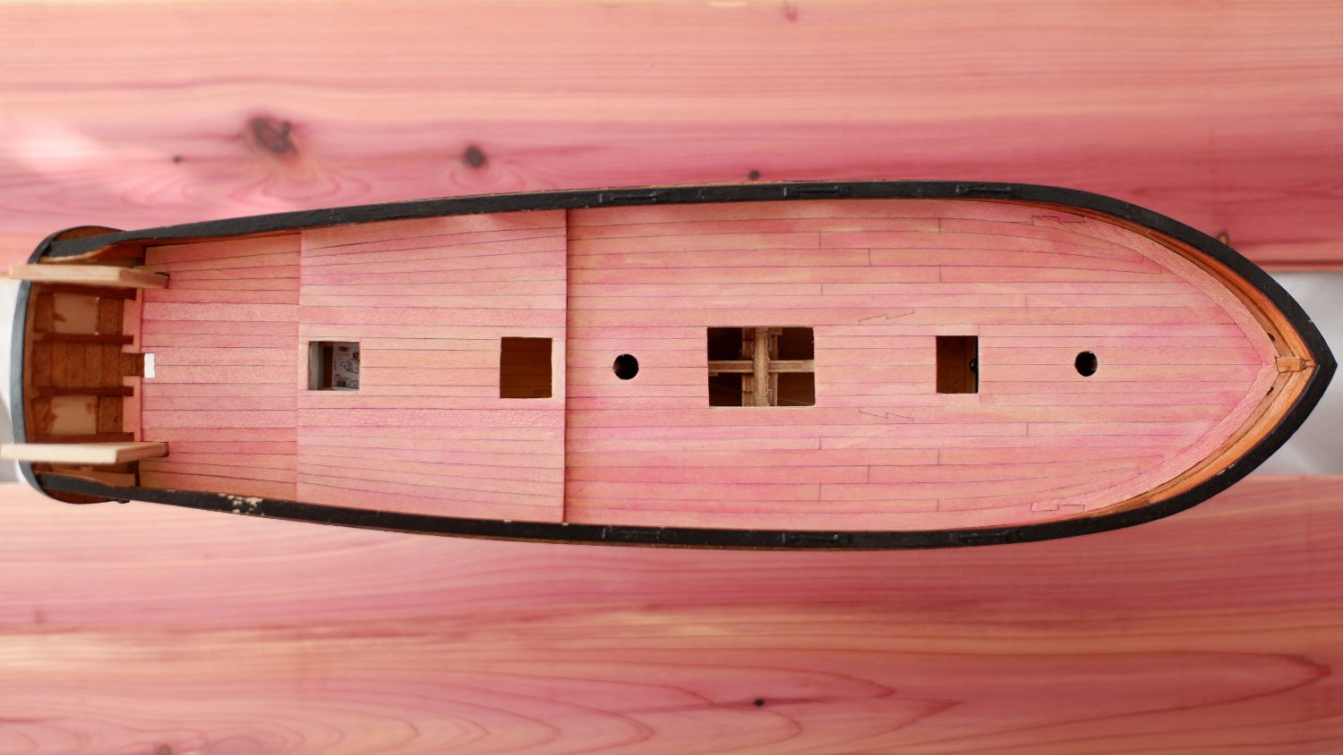
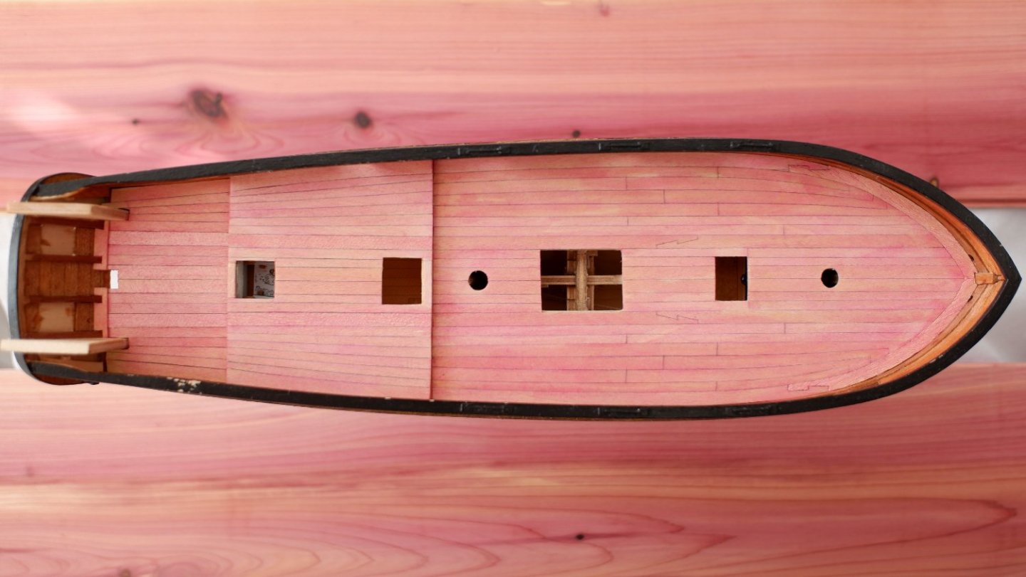
Did someone mention pink? The various craft built in Bermuda used the local wood, called a cedar or juniper, which happens to be pink. The wood would weather in service and become a conventional grey-brown except for the deck which was holystoned and hence retained its pink colour. The photo below is of Whiting (Fish or Ballahoo class) and I have placed some lengths of Eastern Red Cedar next to her to show what the natural wood looks like. (Bermudan cedar is nearly extinct now and Eastern Red Cedar from the USA is a close relative.) The case will have a pink base to emphasize the colour. I am still undecided about putting her name on the stern. George
-
Phil, Have you considered water based wood dyes? These are available in small (10mL) tester bottles for not a lot of money and in a wide range of colours. I have used them to match lime wood to walnut with a bit of trial and error, and even to create pink deck planking for Whiting. The colours are quite strong and I diluted them before applying with a small brush. Repeat coats allow a lot of control of the depth of colour. 10mL is more than enough for a fleet of model ships. I bought from a company with the intriguing name of Woodeedoo but a quick search on Ebay shows plenty of alternatives. George
-
We do our research and analyse the results and plan our model and perform delicate surgery, and then cut a bit off because it looks better. I wonder how much the old shipwrights followed a drawing or used their own judgement when something did not feel right. Congratulations on your superb workmanship. George
-
Beautiful workmanship here, Phil, and I admire your photography. I am relieved that you managed to find the bits on the floor before the carpet monster devoured them. Marquardt describes a jack staff mounted in a groove on the bowsprit cap to carry a jack (flag) on English vessels. He also shows a 'continental' alternative which does not have the jack staff. I took 'continent' to mean 'European continent' but it could also be American. Petrejus in his superb book shows the same groove and states that Irene, in the Dutch navy, had a small copy of the Dutch flag on the jack staff. I have not checked copies of contemporary paintings of American vessels to see if a they show a flag on a jack staff, and have no idea about regulations at the time. What do you think about American practice? Did they have a flag on a jack staff? George
-
Gregg, Neat work with the decking and the margin planks which will provide a good background for all the other bits on the deck later. One comment about the pumps. These would go above the deepest part of the hold which is between the larger grating and the rear mast. The Admiralty drawings clearly put them there and I think that Caldercraft moved them away from a cramped piece of deck for convenience. If you place them between the two gratings then there will be a lot of water sloshing around in the hold. The kit takes a lot of short cuts with accuracy and the choice is yours: build something which you are pleased with and which looks good to a typical person who admires your work, or historical accuracy to please a pedant. George
- 65 replies
-
- 4
-
-
- Ballahoo
- Caldercraft
- (and 1 more)
-
Gregg, Our modelling skills improve with practice and I look back at some of my old models and wonder why I did what I did. We learn and we get better. Most of your second planking will be covered by paint (unless you choose to go with copper...) and that will hide a multitude of sins which other people will never see. So use the filler and sand it smooth. I find a sanding stick is too small for a hull and use a larger block that fits my hand. Pressing the sandpaper with fingers has its merits too and it allows you to feel bumps and dips. Then put on a decent paint job - lots of coats of thinned paint if you use a hairy stick for painting, or use an airbrush. Choose the colour to suit your needs - bright white is a statement but a yellowy cream is closer to reality if you look at the recipes for 'white stuff'. That leaves the second planking above the waterline. If it is good enough on both sides then be happy. If it is good enough on just one side then that is the side to display and leave the other to face the wall. I would recommend that you continue with your Ballahou. You will learn more when you come to the masts and yards and the rigging and the deck furniture, and will look back later and think that you could have done it better. But your appreciative audience at home will be impressed by what you have created. Then when you come to build your next ship it will be better. George
- 65 replies
-
- 2
-
-
- Ballahoo
- Caldercraft
- (and 1 more)
-
Has anyone tried water-based wood dyes to colour rope? I bought a tiny bottle of 'pink' to mimic Bermudan cedar and it works well on wood. Various shades of browns, greys and blacks would allow the creation of ropes in various stages of tarring from fresh to aged. I suspect that natural fibres will take the dye better than artificial but it needs some experimenting. Unfortunately our house is in chaos at present with major renovations so my experimenting will be delayed for a while. Can anyone relate their experience with wood dyes? George