DONATION DRIVE - SUPPORT MSW - DO YOUR PART TO KEEP THIS GREAT FORUM GOING!
×


georgeband
-
Posts
304 -
Joined
-
Last visited
Content Type
Profiles
Forums
Gallery
Events
Everything posted by georgeband
-
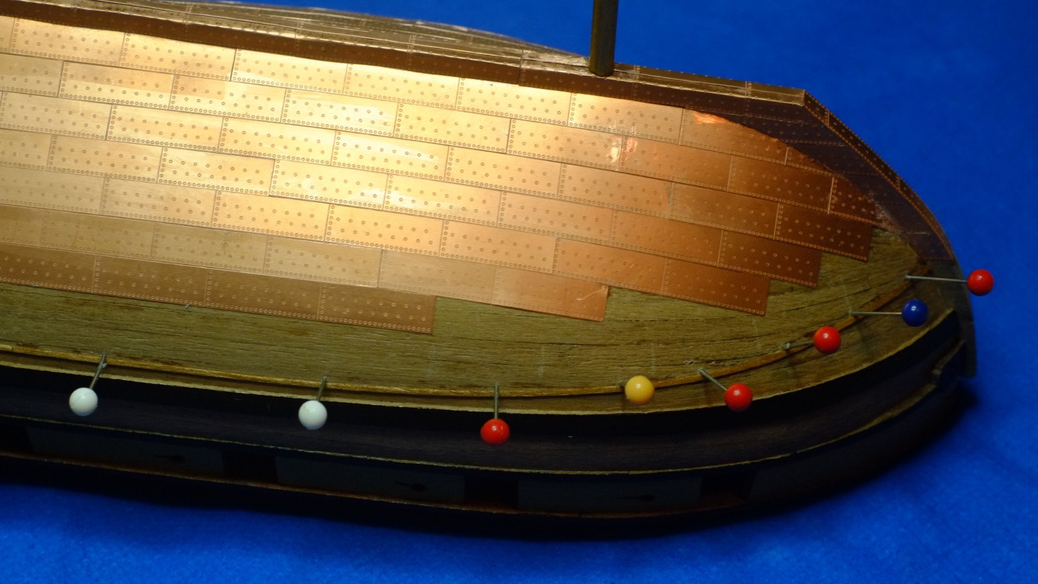
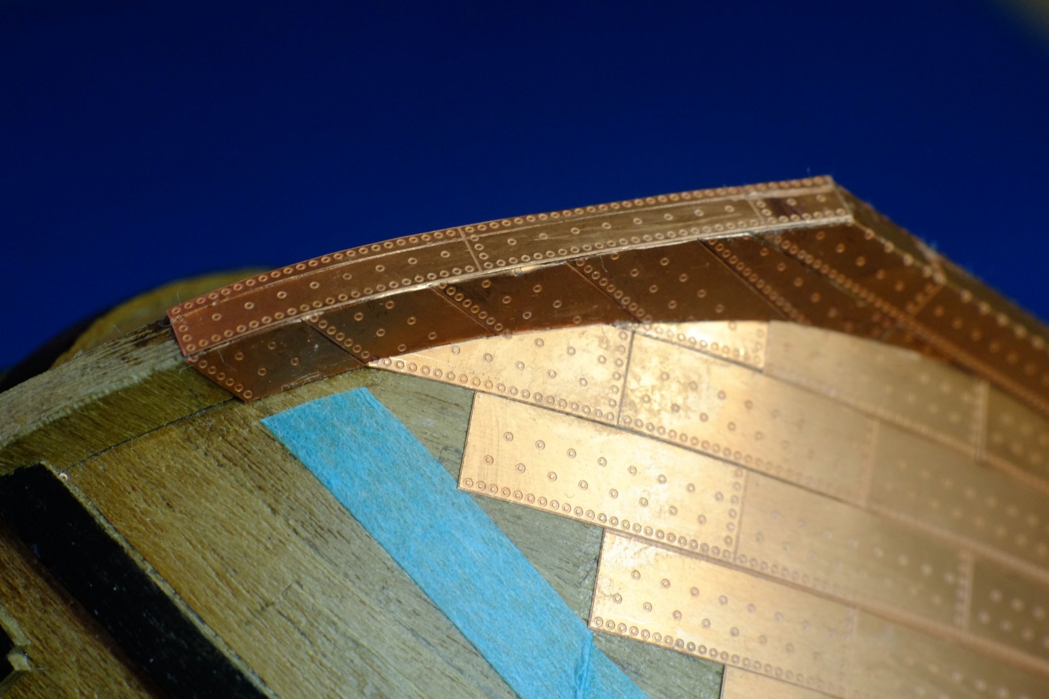
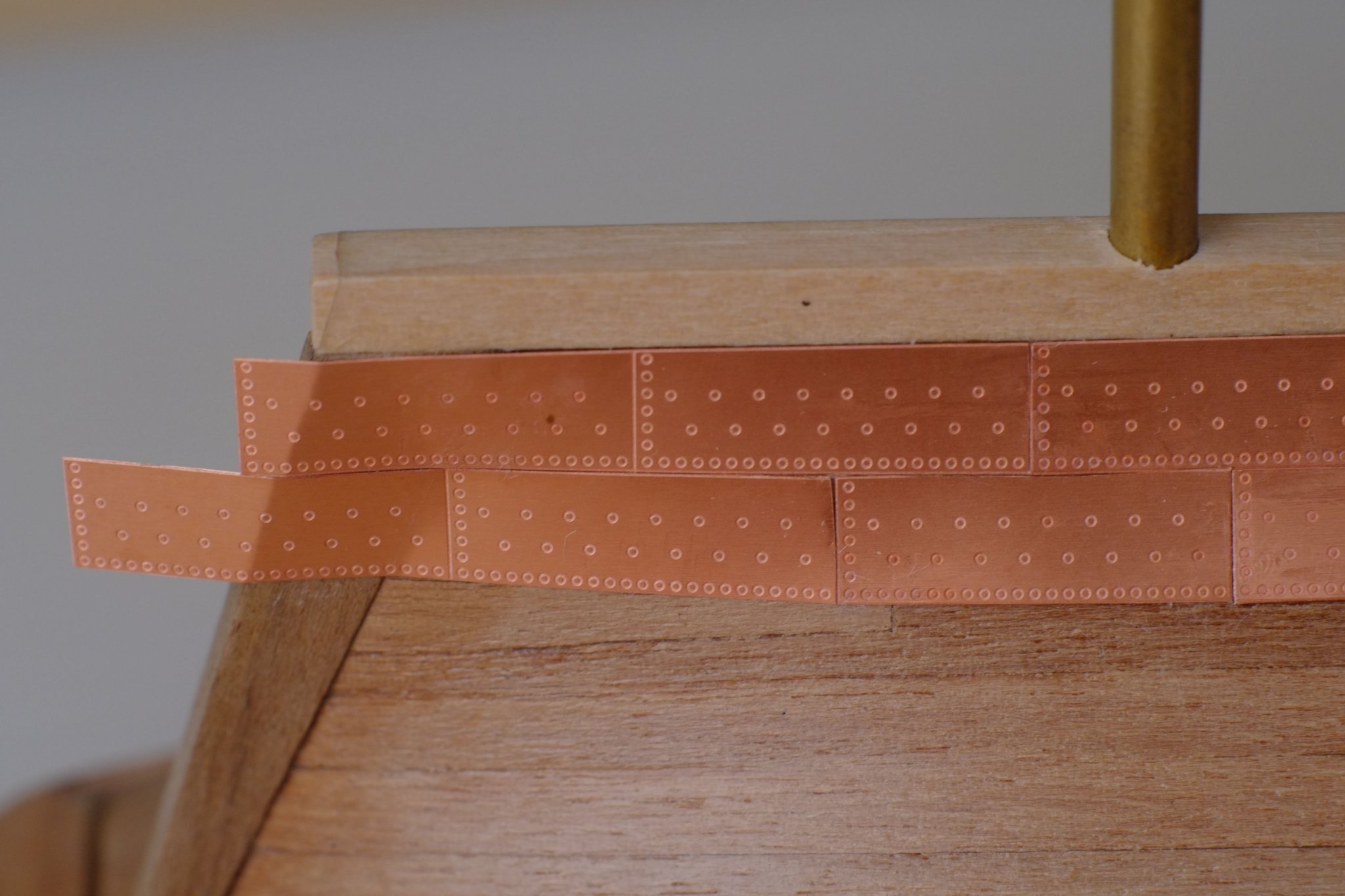
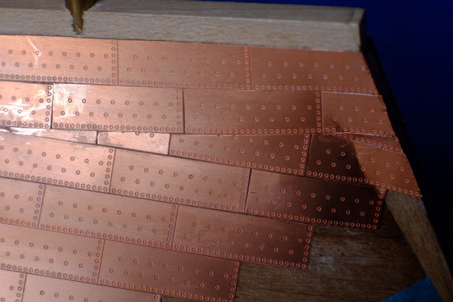
 The copper plating continues. I have now glued the row of plates that lies along the waterline, port first and then starboard. The first step was to peel back the 6mm wide masking tape and push pins into the hull on the waterline. (If you do this on both sides then many pins will get knocked out while handling the hull.) Next I cut a 1mm wide strip from the supplied deck planking, which is 0.5mm thick, and dyed it walnut colour. This is then glued onto the hull above the pins. I started at the bow and pre-bent the strip before gluing with CA superglue. Then it was a case of working along the hull and using fingers from one hand to hold the strip against the next couple of pins while the other hand applied a small drop of CA. I used two techniques for the CA: one was to have a large drop on my work mat and I used a long pin to pick up a small drop from it. The other was to put a small drop from the bottle on the pin and then rest it somewhere convenient until the wood strip was positioned properly. Both work, neither is perfect. Pins along the waterline to align a thin wood strip At the stern the strip is bent and twisted to follow the waterline, and cut to length where it meets the stern post. The wood is thin enough to be pliable and the CA holds it effectively. The vertical joints between the copper plates on the waterline should align with those in the highest row fitted so far (row seven from the keel, see photo above). (This is purely aesthetic on my part and I have no evidence for the practice.) It is important to work from the bow when fitting the plates because of trimming the leading vertical edges, so we need to know where to start. I set a pair of dividers to the length of the plates, aligned one point with one vertical edge in row seven, then stepped along the wood strip. This showed that there should be a small triangular plate at the bow, about 2 to 3mm long on the strip. I made an executive decision to ignore this because it would be structurally weak and on my Whiting the first full plate started at the bow. With hindsight, I should have fitted the waterline row first and then plated the rest of the hull to match the vertical joints, starting from the keel. The Amati plates come in port and starboard flavours. For the waterline row I used the 'wrong' version so that the edges with many nail marks were facing aft and down. 'Facing aft' is sensible because the overlap suits the flow of the water. 'Facing down' has no evidence, again, but it seems more likely because the shipwright could attain a neater line with these plates than with the sloping and tapering ones which meet them. From a practical, modelling perspective it would be very difficult to make odd-shaped plates that had the full set of nail marks on three or four edges. The plates are gently bent and twisted so they lie on the hull, and then a triangle is cut off from the leading edge so that the plate butts against the one before it. This is vital at the bow and stern but along the middle of the hull the trimming is minor. For small triangles I held a plate with pliers so that a long edge was resting on my work mat, then cut slivers off the short edge with a knife pushing down. A sliver took off about 0.1mm so the process was quite controllable and a final clean-up with a sanding stick gave a good edge. Where a large triangle had to be removed I used scissors first, then the knife. In a few cases the edges that butt against the wood strip would leave a gap. One method I used to counter this was to trim the long edge into a shallow curve, the other was to run a knife point along the wood strip to make a groove that hides the copper: this was better. Gluing the individual plates with CA needs three hands unless you have a method for applying small drops, as for the wooden strip above. Once one drop grabs and stops the plate from sliding it is easy to apply more drops around the edges of the plate, pressing the plate down to expel the air from any remaining gap. Plates fitted on the waterline Both waterline rows are now in place and the next job is to start filling in the gaps. Lots of trimming to come. George
-
Avi, Here are a couple of photos of the two styles. The first one shows hooked ends to three deck planks. The planks themselves are tapered and curved which reduces the number of hooks, and at the stern the tapering removes the need for hooks or nibbles. The photo also shows hooked scarf joints. The pink colour is deliberate for this Bermuda built schooner. The second picture is of a cutter and has nibbling, also called joggling (please correct me anyone if my definitions are wrong). I used a cheat method for the joggling, which was to first take the planks right up to the bulwarks. The waterway is cut from paper and is glued on top of the deck planks. This is much easier than trying to match cuts in the wood but depends on finding paper of the right colour. (The joggling on this model is quite extreme and the deck planks near the centre line could just have the ends cut at an angle to match a plain waterway.) Hope this helps, George

-
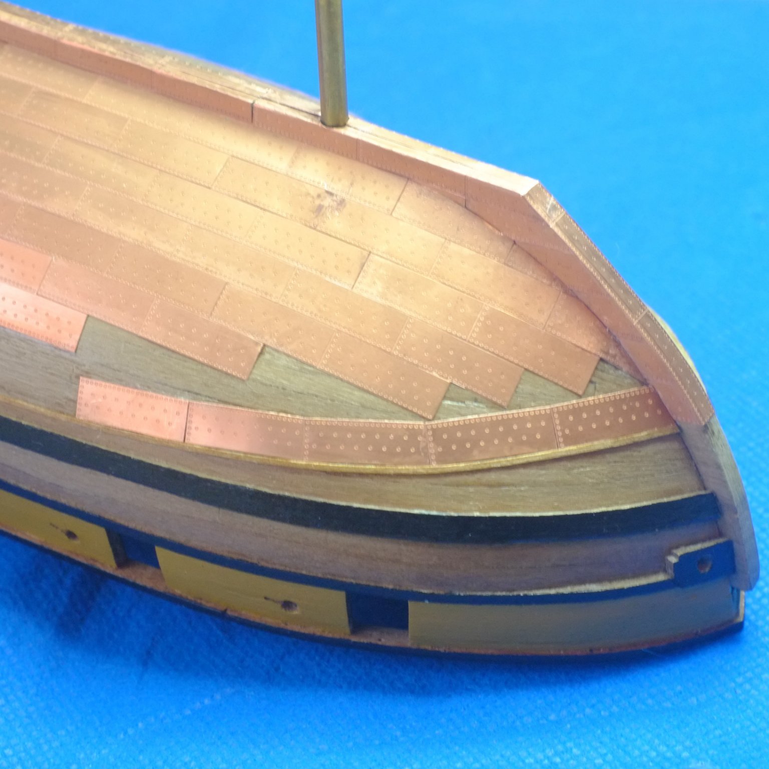
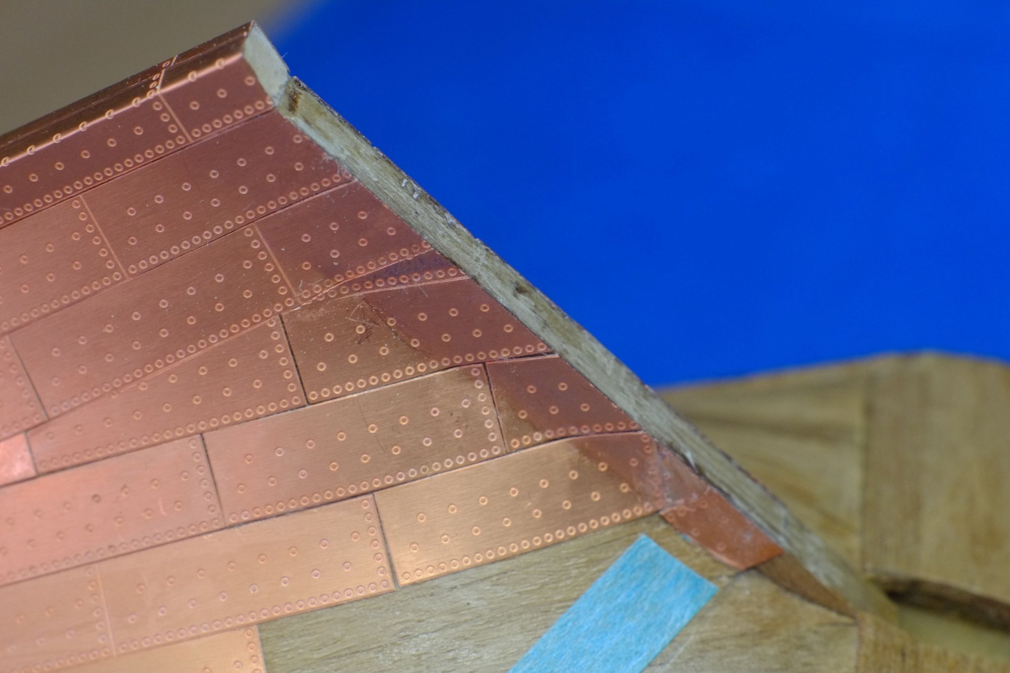
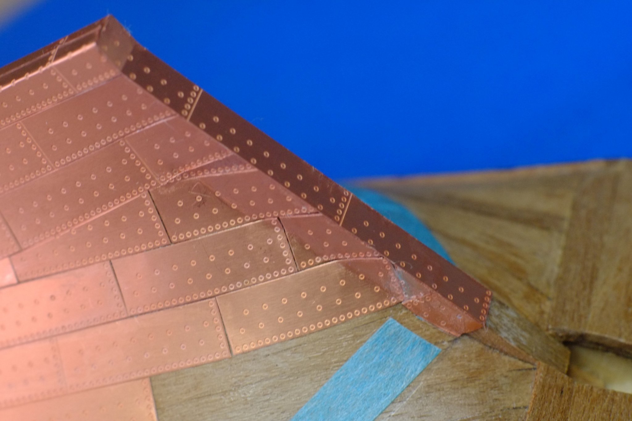
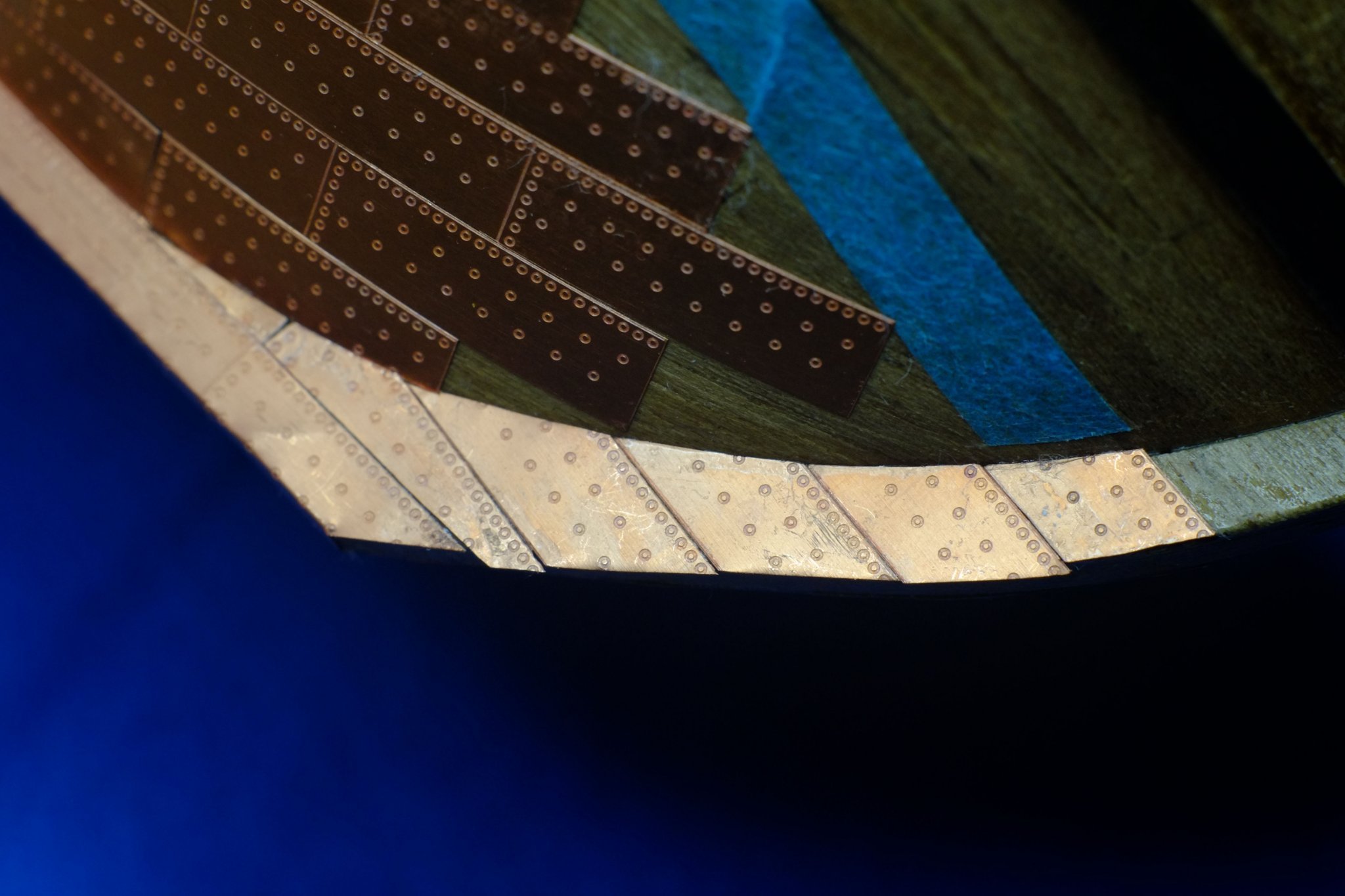
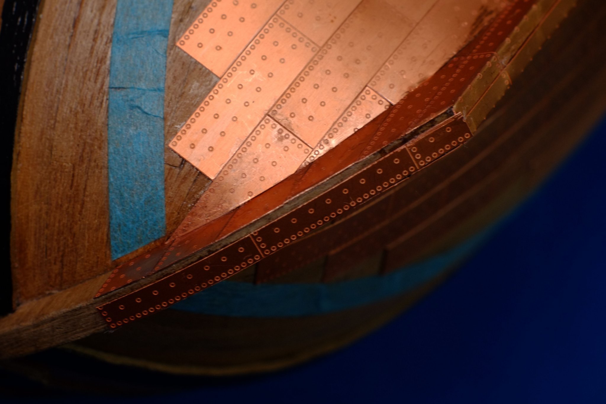
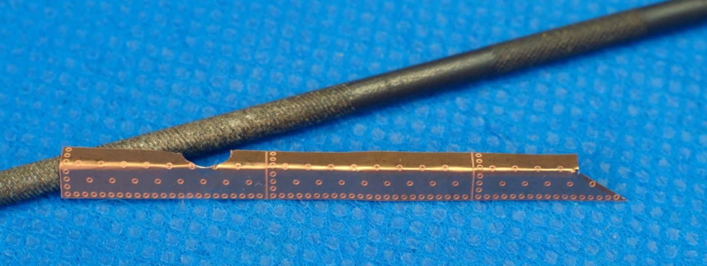
More coppering, this time doing the complicated bits at the stern, keel and bow. Keel The main run of the keel was laid as a long strip, glued to one side. I then carefully bent the strip along its length so that it also covered half the lower face of the keel. Repeat the process for the other side of the hull and most of the keel is covered, though with an overlap between the two strips. I considered cutting back one or both sides to give a butt joint, but chose the easier solution because the bottom face of the keel will not be visible. The front and rear portions of the keel include the support stands. I pre-bent the copper strips and filed in a semicircle to fit around the stand. Then it was gluing and overlapping at the bottom. Fore, port section of the keel with my 50 year old needle file Keel, aft end, with copper fitted around the stand Stern post I had continued the run of plates from the hull onto the stern post, bending them where necessary. The protruding ends were cut back in three stages: 1) cut with scissors or end-cutters, 2) cut with a knife, removing small slivers, 3) filing with a sanding stick. I then reduced the width of a short strip of plates by cutting off the heavily nailed edge and glued it over the end face of the stern post. I guess that the shipwrights would do this, or lay the plates horizontally. The finished result on the model will be mostly hidden by the rudder so it makes little difference. Plates extending from the hull onto the sides of the stern post Stern post with plates on the end face Bow / stem post Unlike the stern post, I plated the bow separately from the hull. I cut and fitted pieces to the sides starting from the waterline and working down to the keel, trying to keep parallel to the waterline. The piece next to the keel was a complicated shape and needed a lot of trimming and test fitting. After these pieces I filled in the gaps on the hull, again with more trimming and test fitting. Side face of the stem post. The ends have not been cut back and the remaining plates on the hull have not been fitted yet I wanted to represent the nails on the front face of the stem post and achieved this with two strips of plates. One was the offcut from the stern with lots of nails, the other was about 3.5mm wide and the pair give a symmetrical look to the nail pattern. The vertical join between them is sometimes visible, depending on the angle of the light. Wide strip fitted to front face of bow Front face of bow fully plated. The join between the left and right sides is visible here There is one more coppering job to do, which is up to the waterline. I plan to glue a thin wooden strip (1mm x 0.5mm?) above the top edge of the blue tape, then use that as a datum for the plates which will need a lot of trimming. In the meantime I think I have earned a beer or two for tonight. George


-
Phil, Excellent work, as always. I have been postponing similar planning for my Whiting (Ballahoo schooner) and can see that I can use yours as a basis. I went through the same exercise with Sherbourne (cutter) and it was tight to find enough belaying points. On Sherbourne I had a few timber heads where two ropes were tied off, and I made a couple of cleats that fixed to the shrouds to belay another line. The rope coils were also a snug fit below the belaying pins, mostly because the diameter of the ropes was too large for scale and the coils were too bulky. At some point you have to stop tweaking the design and start modelling. Will you attach the rigging to the masts and yards before they join each other and the hull, or will you step the masts and fit the spars and then start rigging? I found it better to pre-rig where I could so that I was not trying to perform detailed work at the ends of wobbly sticks, with only my elbows braced for support. The ratlines were one exception where I tied them on after the shrouds had been fitted. More please! I am glad that you are ahead of me with your Albatros because I can make use of your research and analysis. George
-
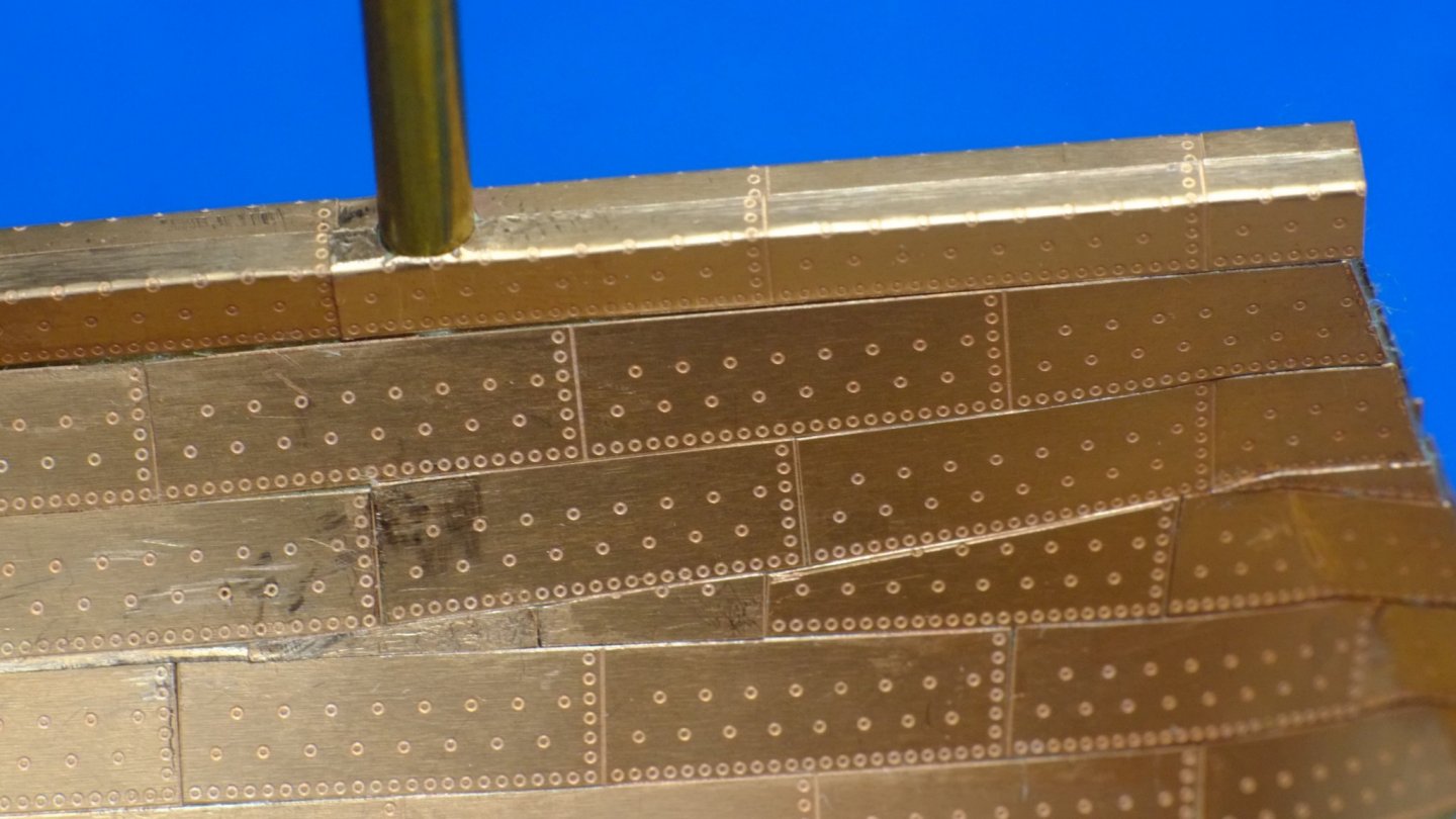
Bit more progress with coppering a lady's bottom. I have fitted the plates which are mostly whole (apart from a little trimming) which leaves the complicated and difficult plates around the edges. It was quite straight forward to fit most of these plates in strips of various lengths. The marks on the photo below are where I scraped away excess CA adhesive. I have completed one difficult bit which is to infill the 'stealer' between rows two and three at the stern. This was time consuming and included holding plates with tweezers so I could cut back an edge with a sanding stick, all under an illuminated magnifier so I could see what I was doing. Differences of 0.1mm are visible so there was a lot of cutting and test fitting before I was satisfied with the result. George
-
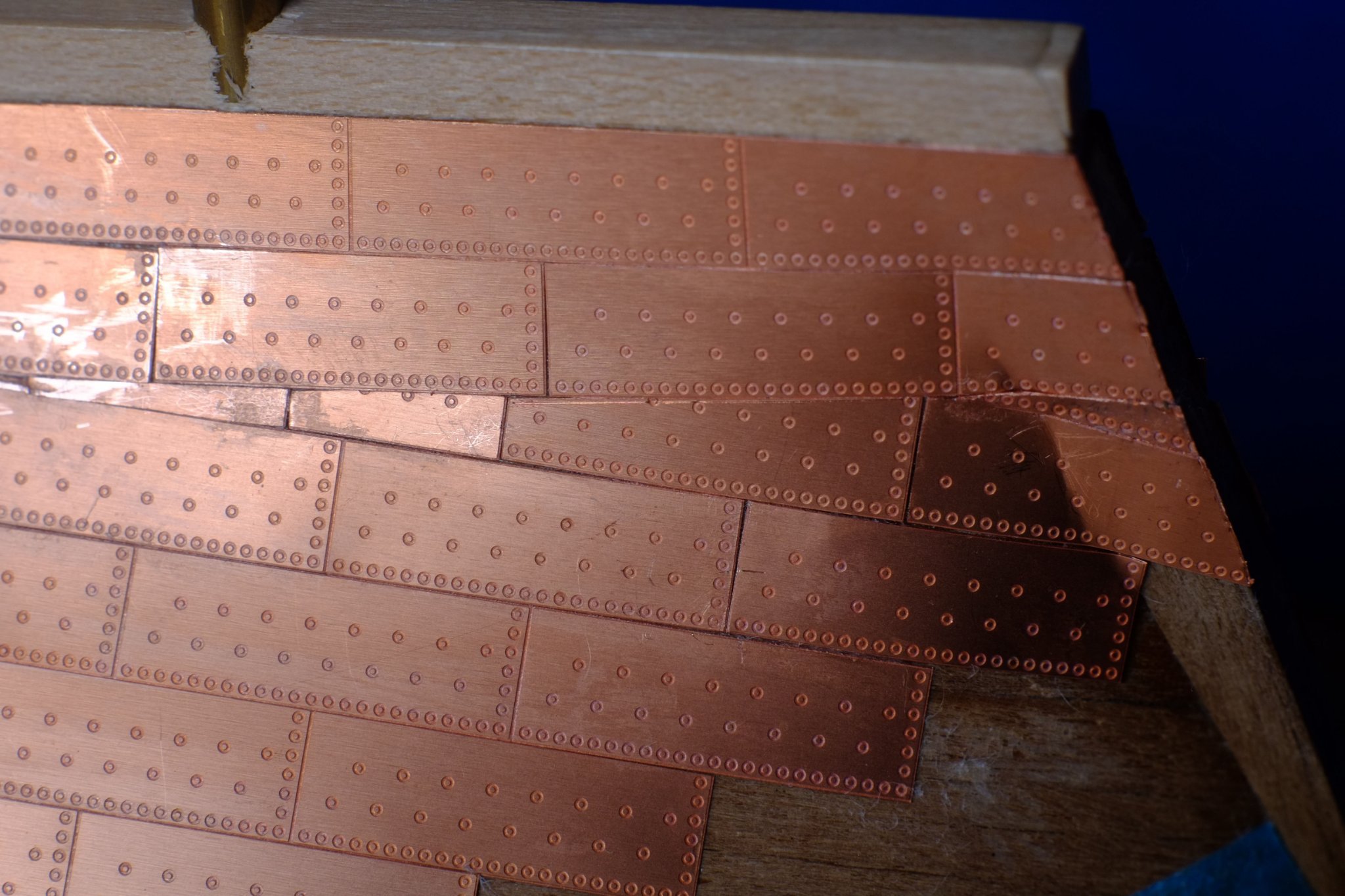
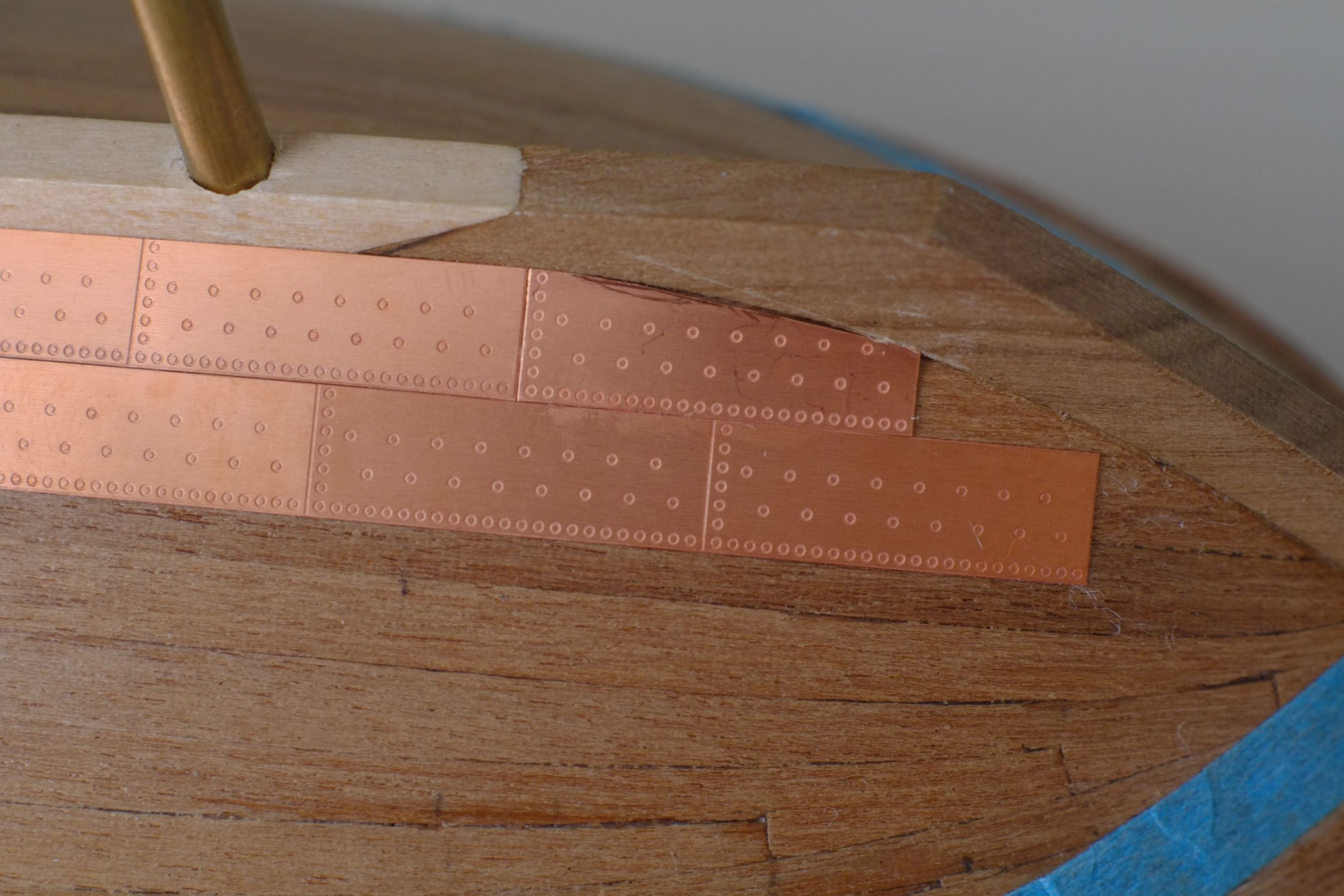
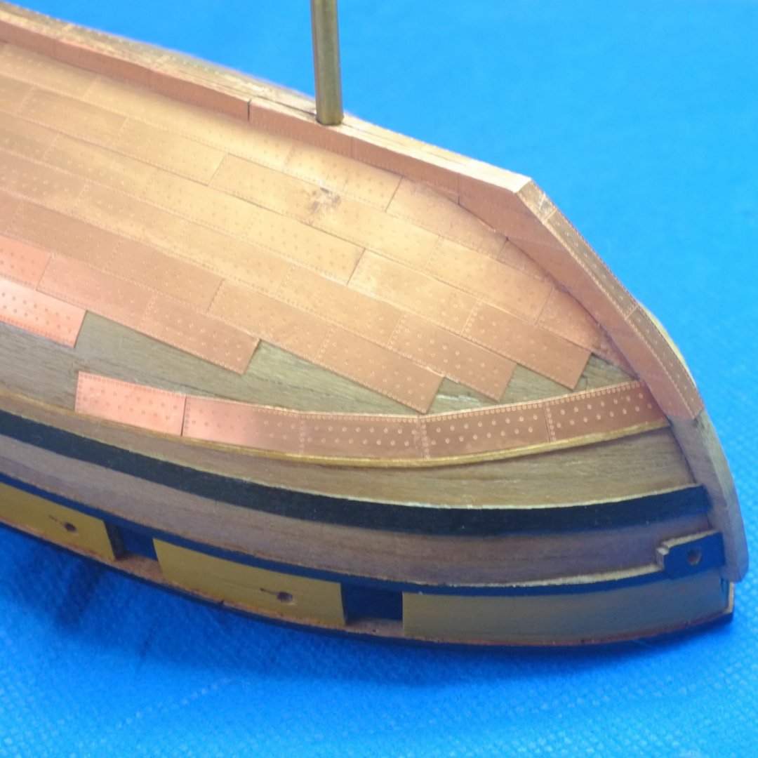
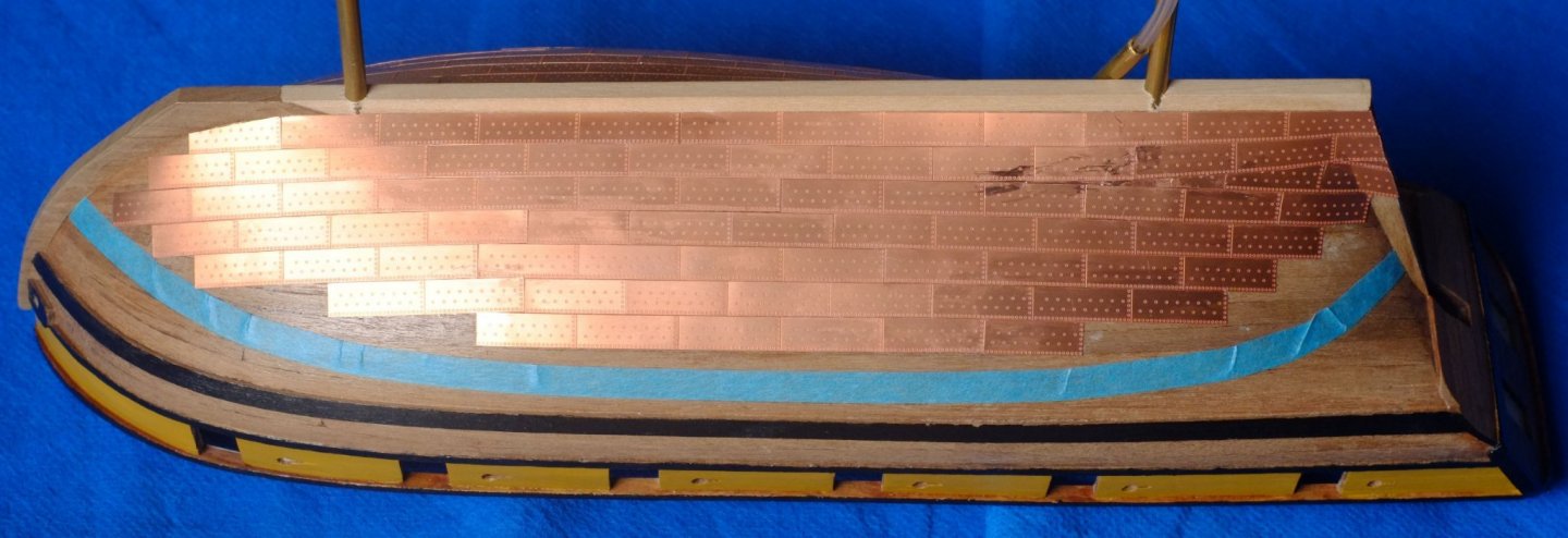
Another three rows of copper plates are now fitted to the hull, mostly in strips. At the bow they curve upwards and leave triangular spaces against the blue tape that marks the top row. At the stern there is a stealer gap that cannot be hidden and I placed it between rows two and three. The strips of plates for rows three, four and five follow their natural lines on the hull. George
-
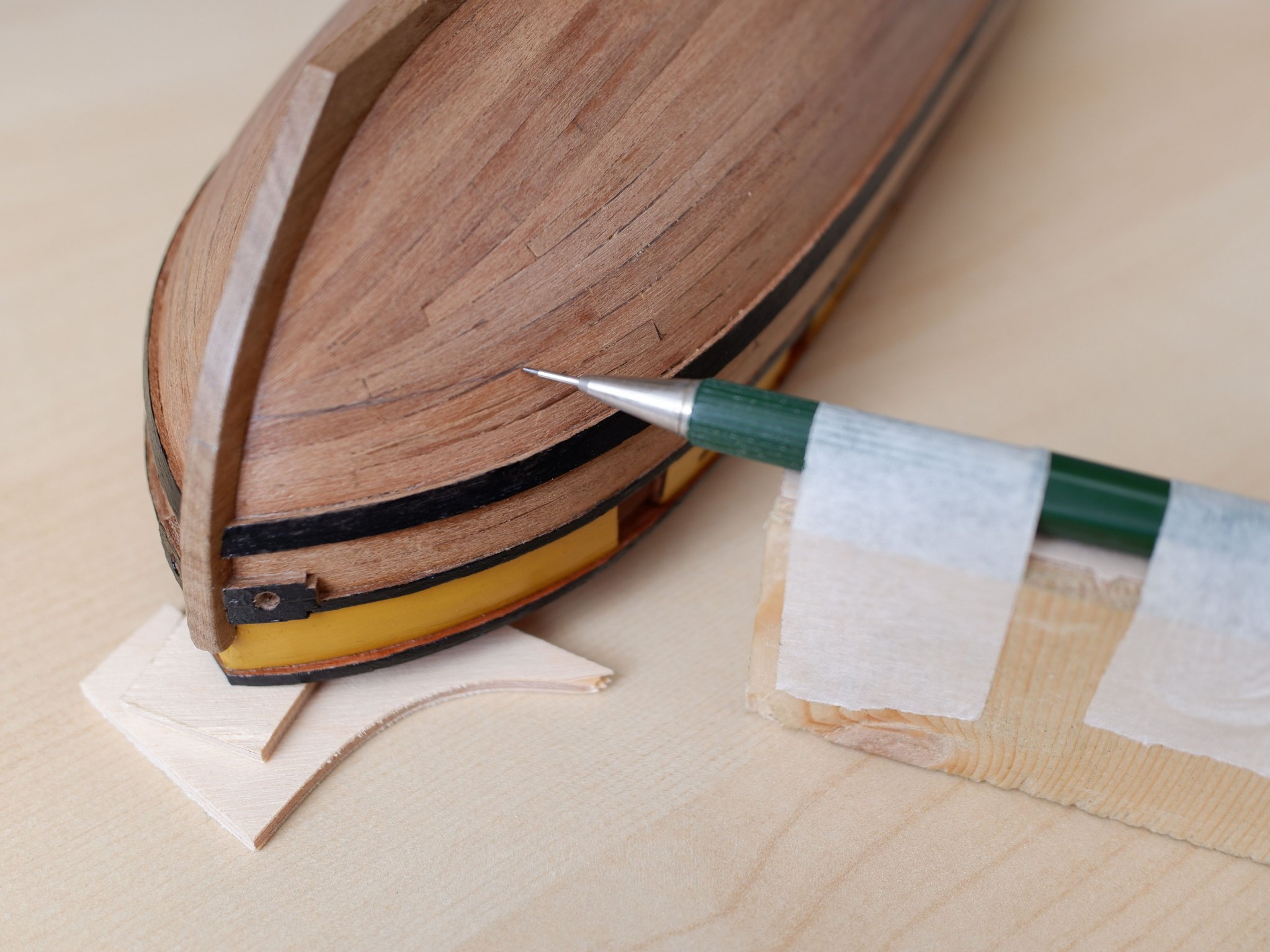
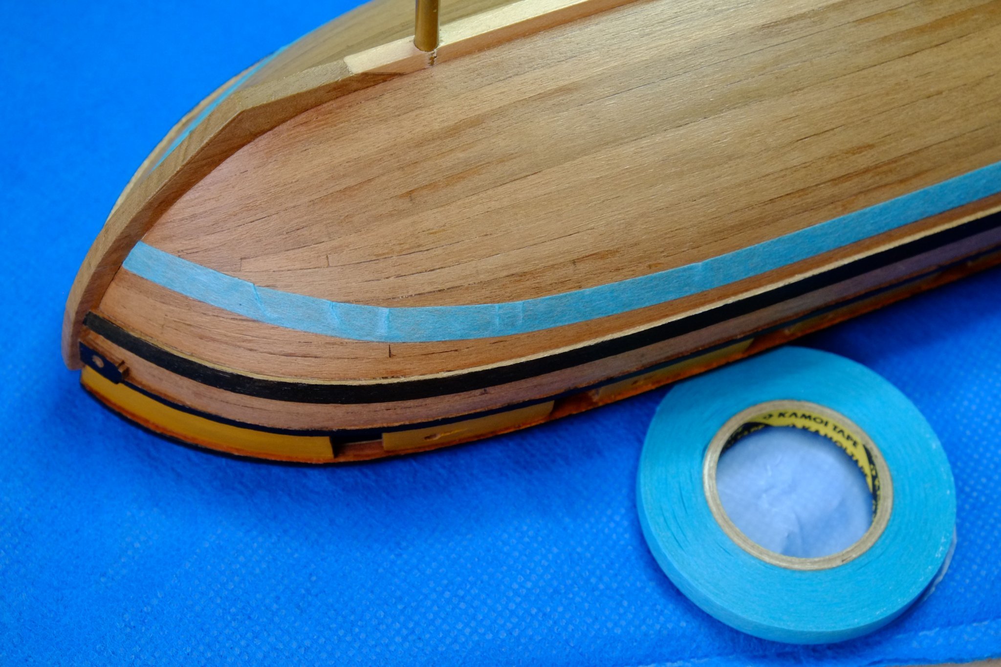
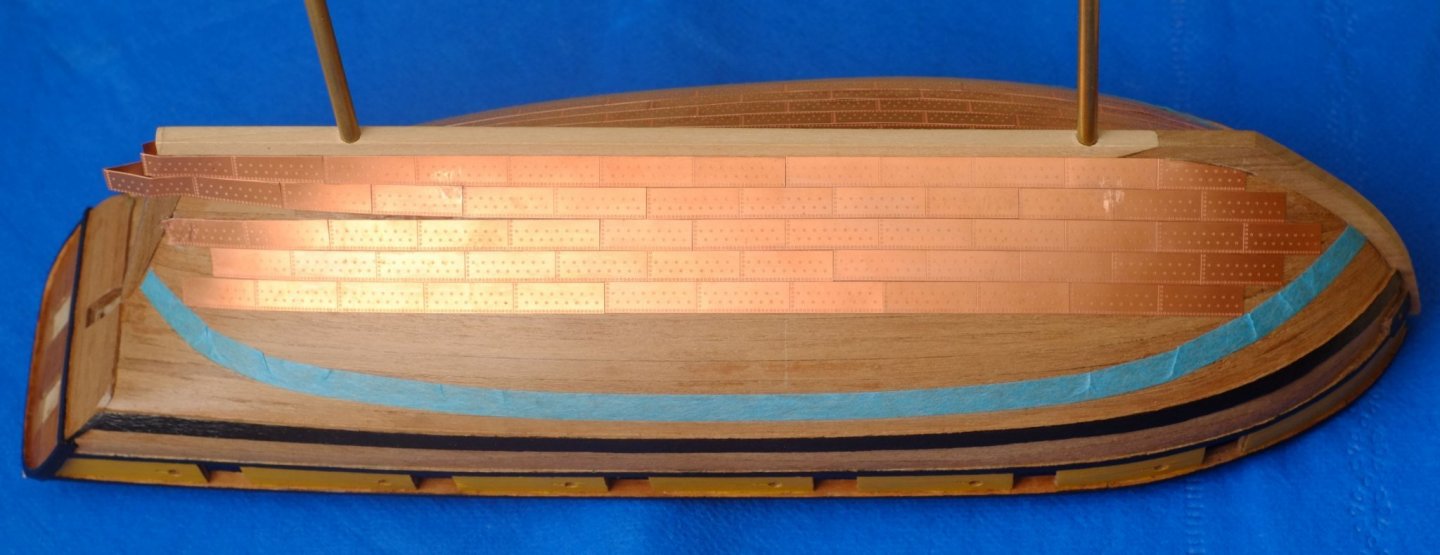
Before fixing the copper plates I marked the waterline in the time-honoured way with the hull upside down and a pencil taped to a block of wood. I then pressed on some 6mm wide masking tape with its upper edge (lower edge on the photo...) aligned with the water line. The top row of the copper plates will run along here and the tape will show me when I need to cut the main plates to fit. Marking the waterline The tape wrinkles around the bow and stern where it curves across its width. The plates here will need careful trimming when I get to them. Masking tape to show the position of the top row of copper plates And the coppering begins. The Amati plates come in two small sheets (port and starboard) and I scored along one of the lines then bent the plate to separate one of the rows. The plates have a fake overlap and do not need a real, physical one on the model, which means that you can apply a strip rather than individual plates. That said, the longest strip that I could fit by the keel was four plates long. Learning points for me: Start at the bow and work towards the stern for any one row. The plates have to be trimmed to fit and it is better to cut back the 'underlap' edge rather than the 'overlap' edge which has extra nail detail on it Make sure that a plate or strip fits by cutting back the 'underlap' edges. I found filing with a sanding stick worked, as did running a knife along the edge to remove fine slivers. Cutting with scissors is good when removing larger areas but cutting with a knife against a ruler, as for wood, distorts the copper To fix a strip, apply cyano acrylate (CA) superglue to the back of the second plate and angle it up slightly from the first plate. Now position the first (dry) plate, hold it down, then fold down the second plate and let the glue grab. Then lift the first plate, apply CA and press it down. The CA grabs quickly and I had to lift a few plates and try again because there were gaps where I did not want them To fix a single plate apply a small drop of CA near one end then position the other end against the adjoining plates. Hold down the end then let the other make contact and press down. If the gaps are too big then the plate is easily pinged off by sliding a knife point under it The glue bond will not always be sound and a lifted edge can be repaired by applying a small drop of CA and then pressing down the plate with a cocktail stick. Wipe away the glue that is squeezed out Fitting planks is easier than fitting copper plates! The three plates further from the keel were applied in one strip. The cut-back plate was then fitted into the gap Plates near the stern were applied in strips or individually. With this magnification the etched joins look different from cut, butt joints. The folded parts on the stern post will be trimmed off later Those two rows of copper plates are about five hours work, but the second side was quicker than the first. It will be a lot more than a couple of evenings to fit them all. George


-
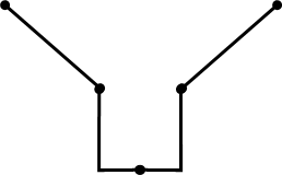
Copper sheathing I have taken a break from model making for a while and am now back and ready for the next stage: copper sheathing of the hull. There is plenty of written evidence which says that the Fish schooners were coppered and it is something that I want to include on Whiting. There has been plenty of discussion in the past about copper sheathing but a dearth of original, contemporary information. It seems that most of what we now think is based on archaeological finds and current opinions. One paper that I have found most useful is 'Introduction to use of copper sheathing' by Staniforth. This is readily available on the web and I downloaded a copy from Academia.edu. Staniforth Introduction_Use_Copper_Sheathing.pdf Staniforth states his references but they are all secondary sources. Old photos of USS Constitution show that the copper plates were originally applied in increasingly curved lines and not in 'belts'. https://ussconstitutionmuseum.org/2016/11/18/new-copper-sheathing-2/. This and the archaeological information in Staniforth's paper convinces me that the sheathing on Whiting does not have 'belts'. The first row of plates was fixed by the keel and the subsequent rows tucked in alongside the one below it. The 'no belt' method leaves a jagged line of plates at the water line. I will have a single row of plates at the top, parallel to the water line, and trim the others to join them. The alternative of a wooden plank to trim the edge does not look as interesting to me. The copper on my Whiting will rise as far as the water line that is shown on the Admiralty drawing which leaves a small exposed area below the main wale. The majority of the plates were overlapped with their neighbours and the rows were offset like brickwork. Along a vertical join the fore plate overlaps the rear plate, which seems entirely sensible given the flow of the water. Staniforth states that for horizontal joins in the Royal Navy the lower plate overlaps the upper, which is more complicated for the shipwright since one row cannot be fully nailed in position until the next row is in place. I have not been able to follow the chain of references so this statement might just be an assertion but it is all I have. The plates around the stem and stern posts have their own complications with joins and I will tackle them later. The plates under the keel must have been applied after the vessel was fixed to her launching sledge and the supports under the keel removed, otherwise the shipwrights would not have room to work. This problem had me trying to guess what they would have done, but in the end I have chosen a solution that is easier to model. On Whiting the keel is 4mm x 4mm and the copper plates are 6.3 mm wide so I will fold two rows of plates over the keel. The sketch below shows a section through the hull and keel with two plates over the keel and regular plates rising up the hull. Materials I quickly discounted the Caldercraft plates which are severely affected by the pox. The two real options are etched plates from Amati and copper tape. I have doubts about the long term stability of the adhesive on copper tapes and considered bare tape as an alternative which could be glued down with cyanoacrylate (CA) super-glue. I wanted some representation of nail patterns on the plates which adds complication to the use of tape. The Amati plates have restrained detail on the surface and are not pre-glued so I can use CA to fix them. They can also be glued in strips for the the lower rows, and trimmed individually for the upper rows which curve up at the bow and stern. This is what I will use. I have eased the hull and brass stands off the temporary base and bought some thin cotton gloves, so all ready to start on the copper sheathing. George
-
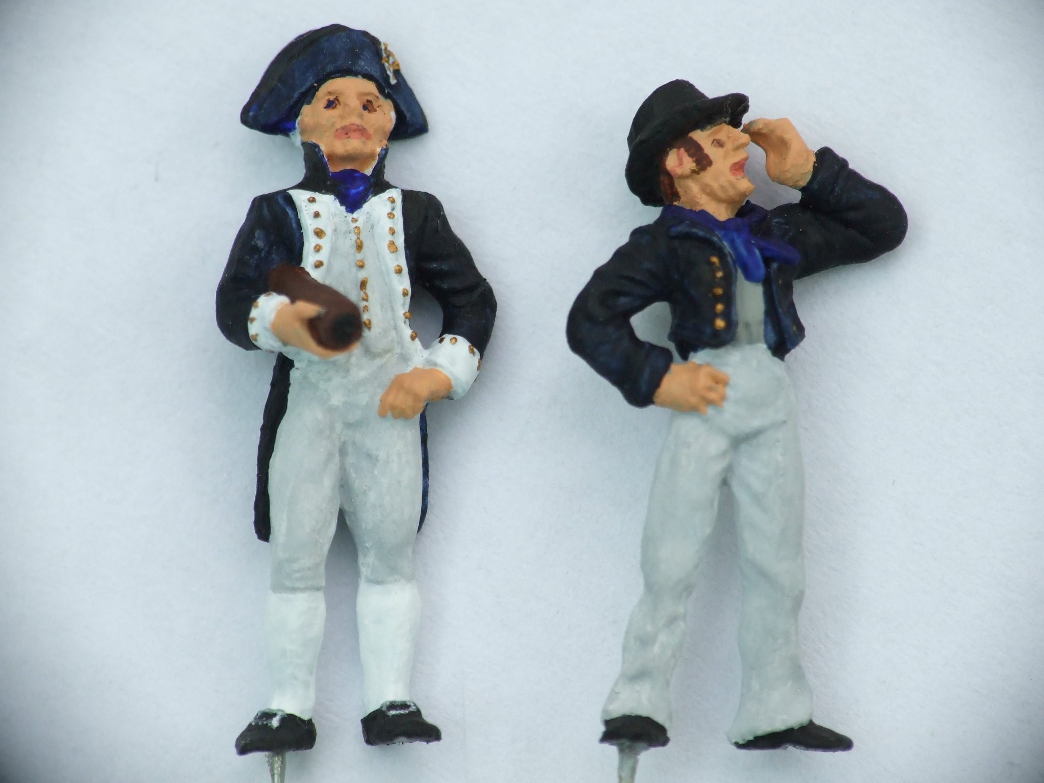
I like to add a couple of crew figures to any model for two reasons - to give a sense of the scale, and to humanize it so that it is not just a machine. In 1/64 scale we appear to be limited to Captain Amati and his crew. Andrew in #5 above gives his captain more detail in the eyes than I have managed with mine. Amati are nicely cast but pricey, and the metal is hard to file so that parts of the figure which require an undercut take a lot of work. The captain's telescope is one example where a fillet of metal has to be removed. I drill a hole into one foot of the figure and glue in a wire so there is something to hold while painting. There is more choice in 1/72 scale and at reasonable prices. HaT make a set of sailors and marines in plastic, and Newline Designs make white metal figures that have realistic proportions. A lot of the wargames figures follow a convention of big hands and big heads so check them before you buy. https://newlinedesigns.co.uk/product-category/newline-designs-20mm-ranges/newline-designs-20mm-ranges-napoleonics/newline-designs-20mm-ranges-napoleonics-naval/ I do not know about other scales such as 1/48. George

-
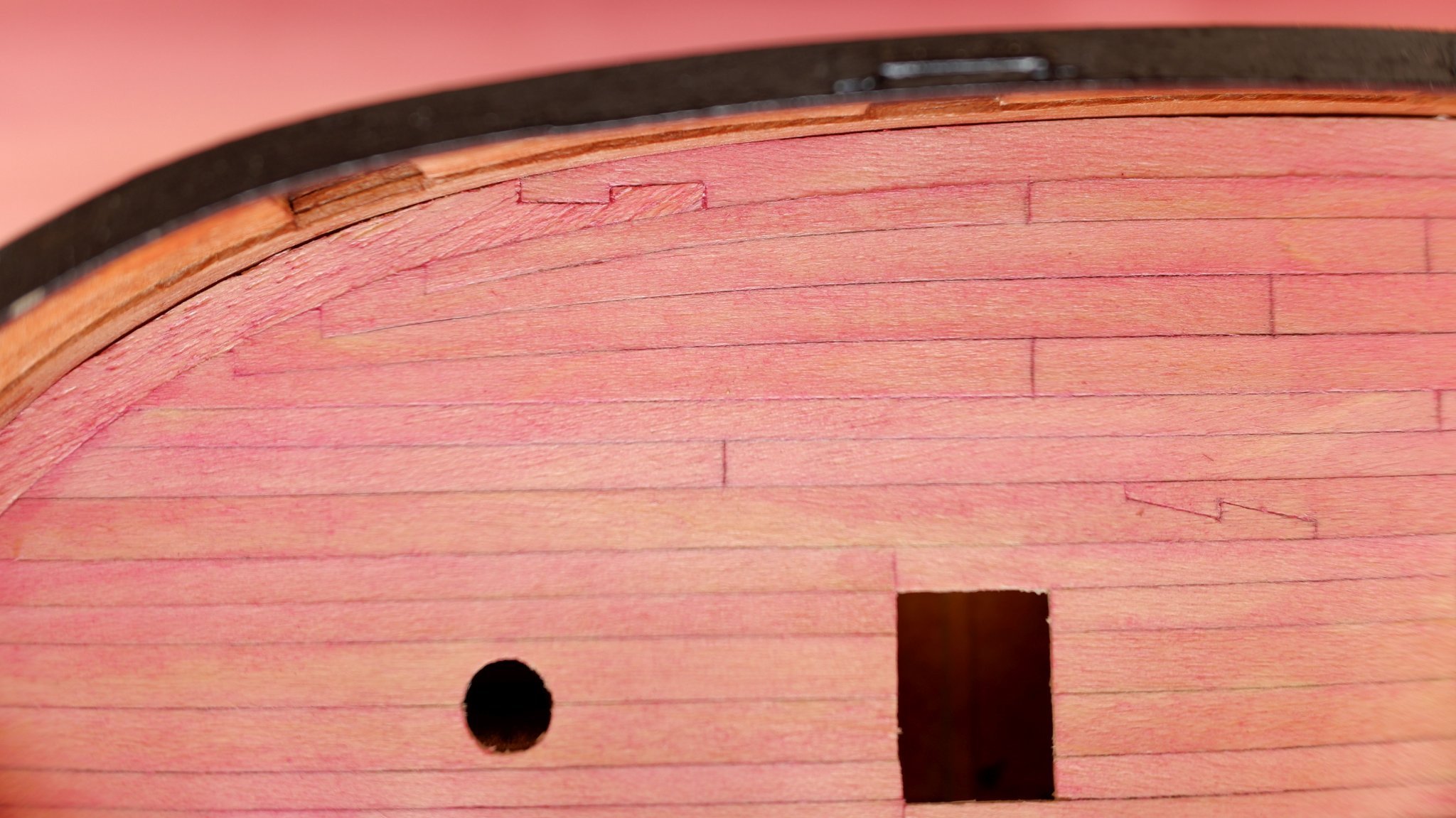
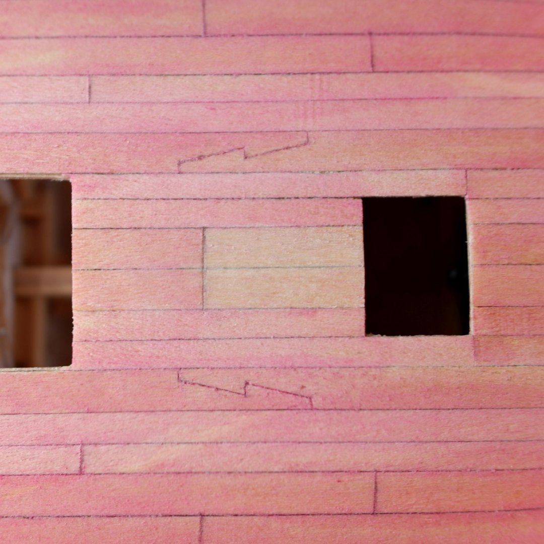
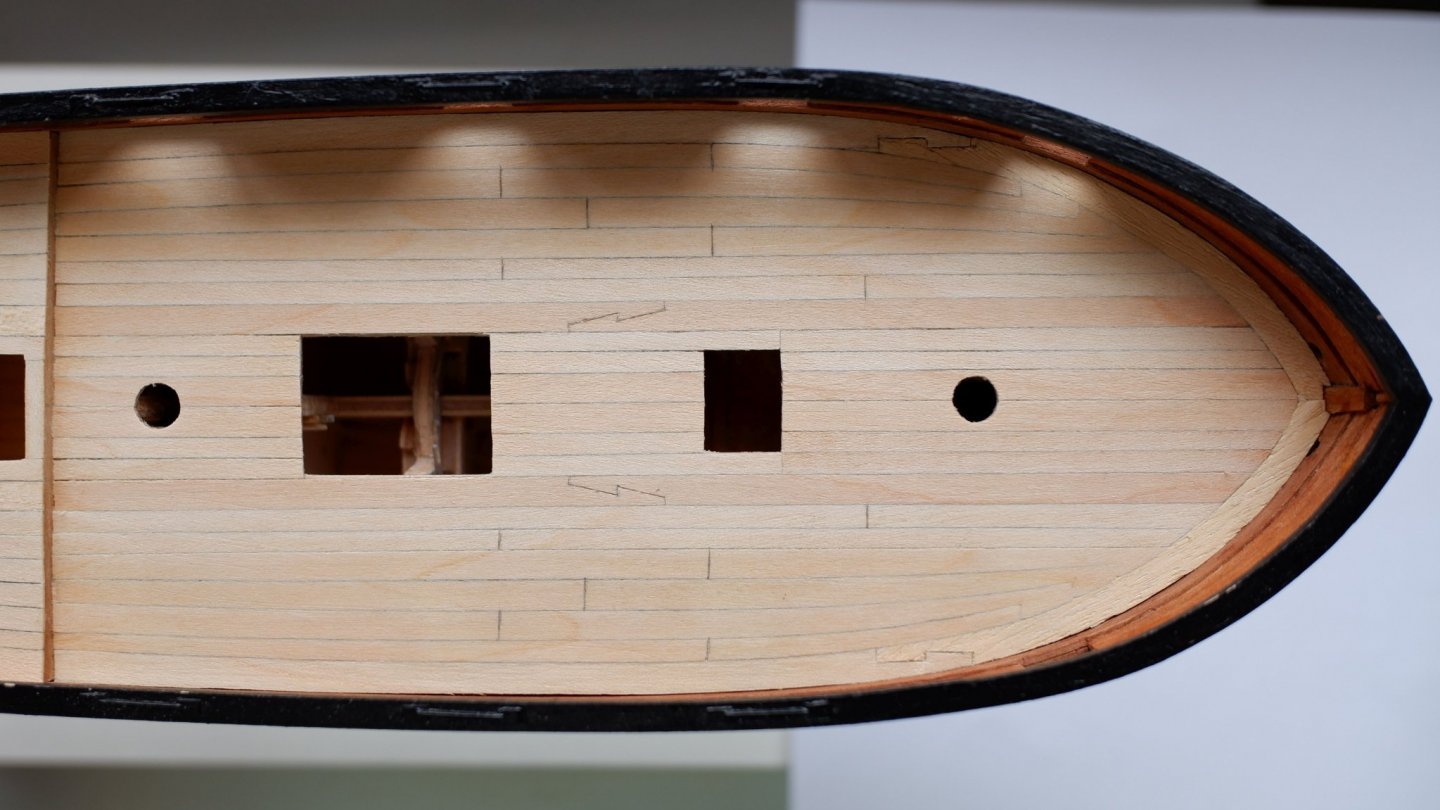
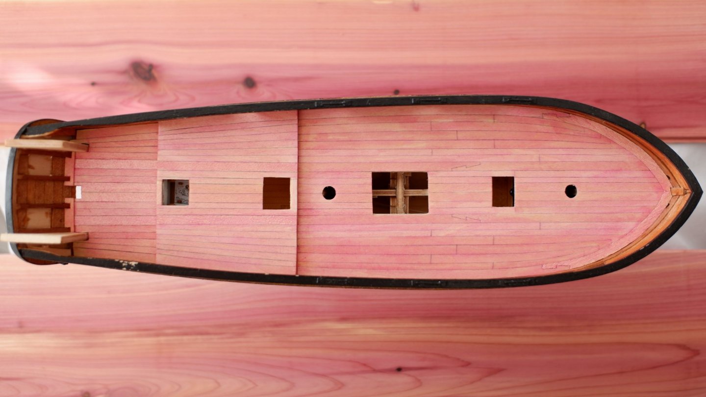
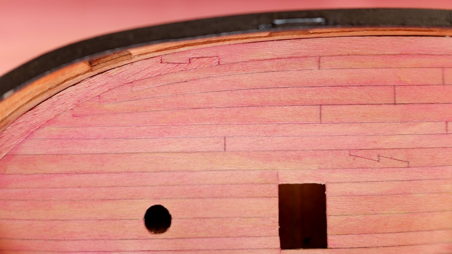
More research on the original drawings for Haddock at Greenwich shows that the cooking range was (very probably) originally aft of the fore ladder way and was moved to the fore position during her refit. What looked like an extra hatch cover aft of the ladder way was (very probably) coamings around the chimney hole and steam vent. Thanks to Jason and Mark for helping with the interpretation. https://modelshipworld.com/topic/29209-hatch-over-a-ladderway/?tab=comments#elControls_846285_menu If you want to model one of the Fish class as they were in the first year of service then the chimney and vent should be aft of the ladder way. I assume that they all had the same refit and around 1806 the cooking range was moved forward. This is what I am doing with Whiting and it leaves the problem of what to do with the redundant chimney hole. The drawing of the deck shows nothing aft of the ladder way so it is unlikely that the coamings were left in place and the holes filled in. The more likely course of action would have been to remove these coamings and put in two new lengths of partner planks. These could run from the main hatch to the fore ladder way, or only over the patched holes. Any guesses? I could justify both options. My guess is that the new deck planks would only cover the old holes. They are (very probably) of the fir used in England for decking and will look different from the pink Bermuda cedar around them. I scored a join line across the partner planks, 13mm forward of the main hatch and 16mm aft of the ladder way, which is above a deck beam. I prepared myself to cut out the deck planks between the scored line and the ladder way and glue in new lengths of 'white' Tanganyika. Fortunately this was not necessary because some gentle scraping with a knife blade took off the pink, dyed layer and exposed the original wood. My deck now has two short lengths of fir among all the pink planks. A little pencil dust adds some emphasis to the joint. Deck between main hatch (left) and fore ladder way (right). Two partner planks in 'fir' cover the old chimney and vent holes
-
Phil, Thanks for the two photos which show a well crafted original. They are not too late and serve as inspiration for the aft ladder way on Whiting which did have a large 'box' over it. I still don't know whether that one will be sliding or hinged on my model unless some letter or log book appears with a revelation. George
-
Jason, Mark, Thank you for your comments. I must agree that you sound right with your interpretation of that part of the drawing, aft of the ladder way. However, there is also a mirror-image cooking range forward of the ladder way. One of these cooking ranges shows what it was like as-built, and the other after the refit modifications. My thoughts are that the original position was aft of the ladder way and the refit position forward. My reasons are The deck plans ZAZ6117 show a chimney hole above the forward location. There is not even a smudge for the aft location ZAZ6117 for the lower deck shows the base for the cooking range, labelled as 'fire place', forward of the ladder way and a scuttle for coals next to it The plans originally sent to Bermuda, ZAZ6114, have the cooking range in the aft position. The deck plan shows a square opening aft of the ladder way (steam vent?) and another one aft of that for the chimney, see below. (They also show a windlass which was not fitted to Haddock. Please see my build log for new evidence about this.) The drawing for Cuckoo, ZAZ6320, is dated January 1806, three months after the Haddock drawings. This drawing was used to build the Bird class in England. The copy I have is not very clear but it shows the cooking range and chimney in the forward position only. I cannot see the extra hatch or coaming aft of the ladder way but this might be because of the poor resolution on my drawing. I think in summary that everyone is right. Jason's and Mark's interpretations are backed up totally by the ZAZ6114 drawing (and other evidence no doubt) but Haddock went through a refit. My interpretation is that the cooking range and associated hatches started as in ZAZ6114 but were moved to a forward location during her refit. Which still leaves me with the problem of how to model the patched-over hatches aft of the ladder way. The pictures below are extracts from ZAZ6114, the drawings sent to Bermuda
-
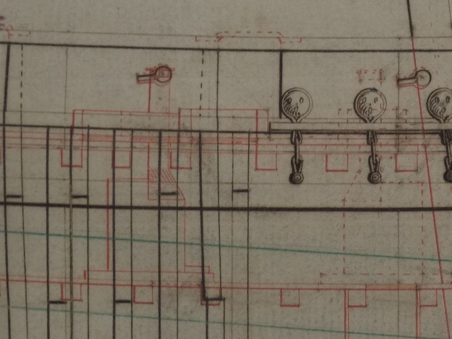
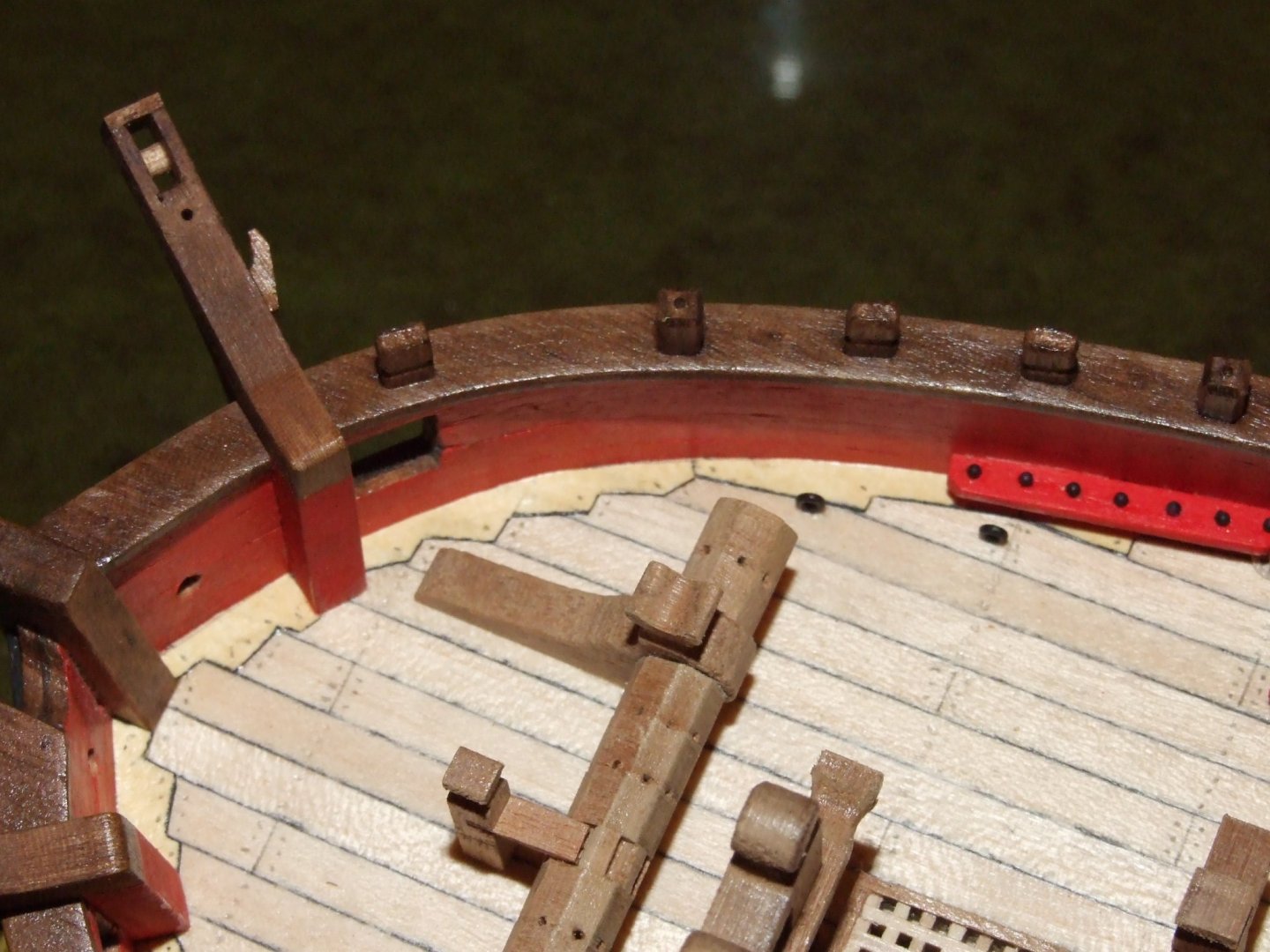
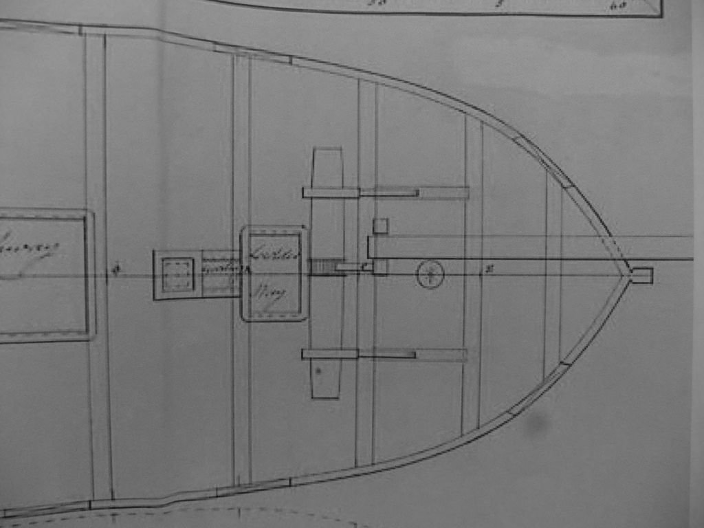
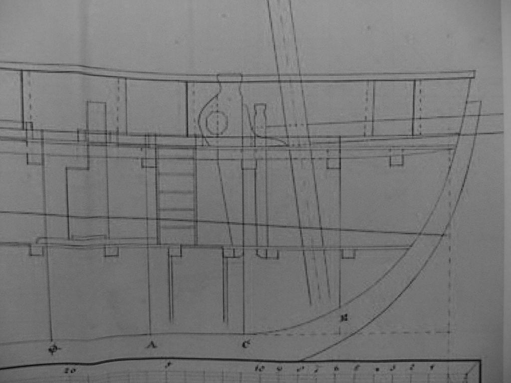
I visited the plans section of the National Maritime Museum yesterday and had a look at the original drawings taken from Haddock. A closer look at a photo when I got home reveals some extra clues about the 'hatch cover' that extends aft from the fore ladder way. Aft of the ladder way, below deck, we can see the cooking range with its chimney rising up through the deck. The top of the chimney is level with the keyhole shaped hole for the sweep port in the bulwark. The coaming that runs back from the ladder way encloses the base of the chimney. I expect that the cover for the ladder way was hinged at its aft end and rested against the chimney when it was open; it could not slide back with a chimney in the way. I had seen but not previously recognised this cooking range, guided in part by the chimney hole on the deck plan. The drawing shows 'changes as dotted lines' and forward of the ladder way, below deck, there is a mirror image of the cooking range. The top of the chimney appears as a crown above the shocked face which is the middle deadeye! The chimney aligns with the 'chimney hole' that is marked on the plan for the deck and my interpretation is that the cooking range was moved forward as part of the refit. (Some of the drawings for precursors of the Fish class before they finalised the design show the range in this aft position. I cannot check at the moment.) The picture above shows a small coaming around the chimney in its forward position. So what happened to the old chimney hole and its coaming? A closer look shows more dotted lines between the chimney and the aft end of the original coaming; these could be the rear edge of a new, smaller cover over the old chimney hole. Some of the deck planks are shaded where there are, or were, openings in the deck but I do not know what this tells me. Would the partner planks that hold the aft mast be patched, or would they be replaced over their length from hatch to hatch? I doubt if a hinged hatch cover over the fore ladder way would be replaced by a sliding one, if only because it is a lot of work. There might be a light weight structure to stop it falling right back when it is open. My inclination now is to model Whiting this way Chimney in the forward position as originally planned Hatch cover hinged on its aft edge, with a frame to hold it at an angle when it is open A circle of wood in the deck where the chimney had been, possibly disguised or strengthened by the support for the open hatch cover So what do you all think? I will happily read what you have say and might change my mind yet. There are a couple of other discoveries that I have put on my build log. George

-
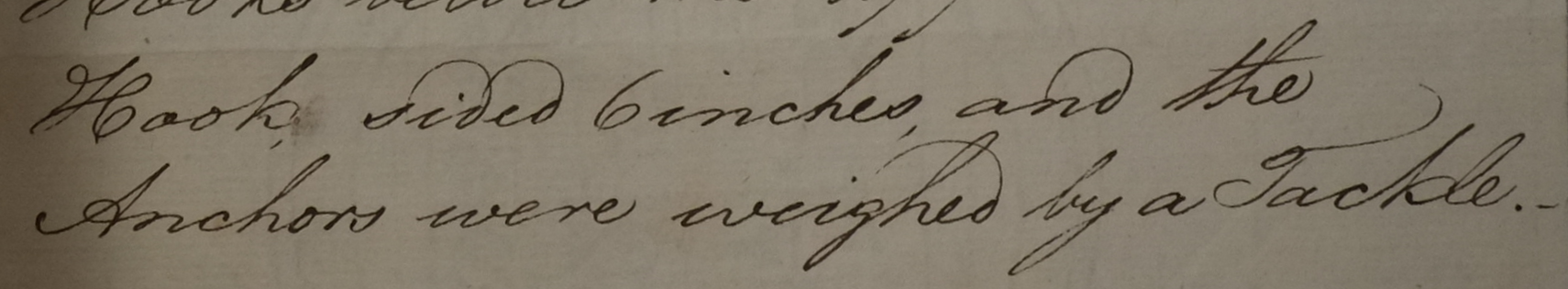
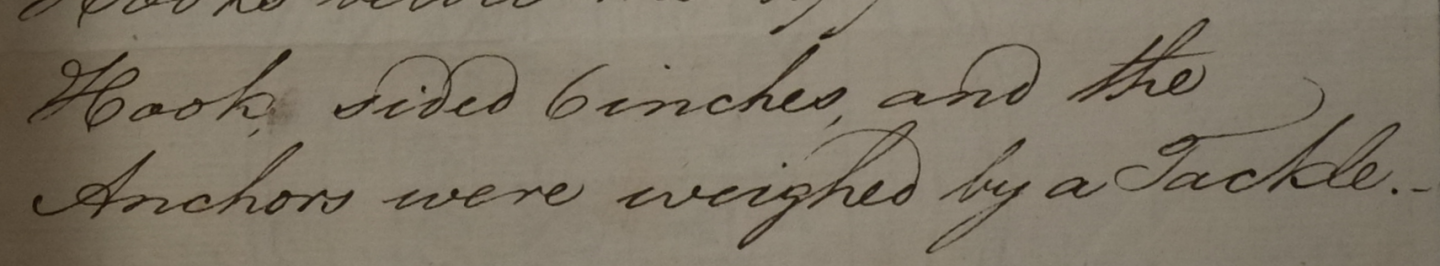
Anchor aweigh and breasthook Yesterday I visited the plans section at the National Maritime Museum in Greenwich and had a look at the original drawings for Haddock. (No touching allowed!) The site is 2 miles from the main NMM buildings and quite forbidding, but the staff were very helpful and friendly. ZAZ6118 is the drawing with scantlings and a cross section of the hull, and an intriguing note about an attached letter that has not been digitised. Two comments in the letter are particularly useful: '... she had one Breasthook above the Bowspreet'. This tells me that I should join the bulwarks together above the bowsprit with a hooked timber and not some combination of iron straps. '... and the Anchors were weighed by a Tackle.' This closes the discussion from 2015 at the head of this thread about whether Haddock should have a windlass and the drawings have an omission. No windlass. A block and tackle would have been used to raise the anchors. The joy of research and discoveries like this is a great source of pleasure for me. We don't have to rely on drawings or contemporary models alone and the hand-written word can be just as valuable. George
-
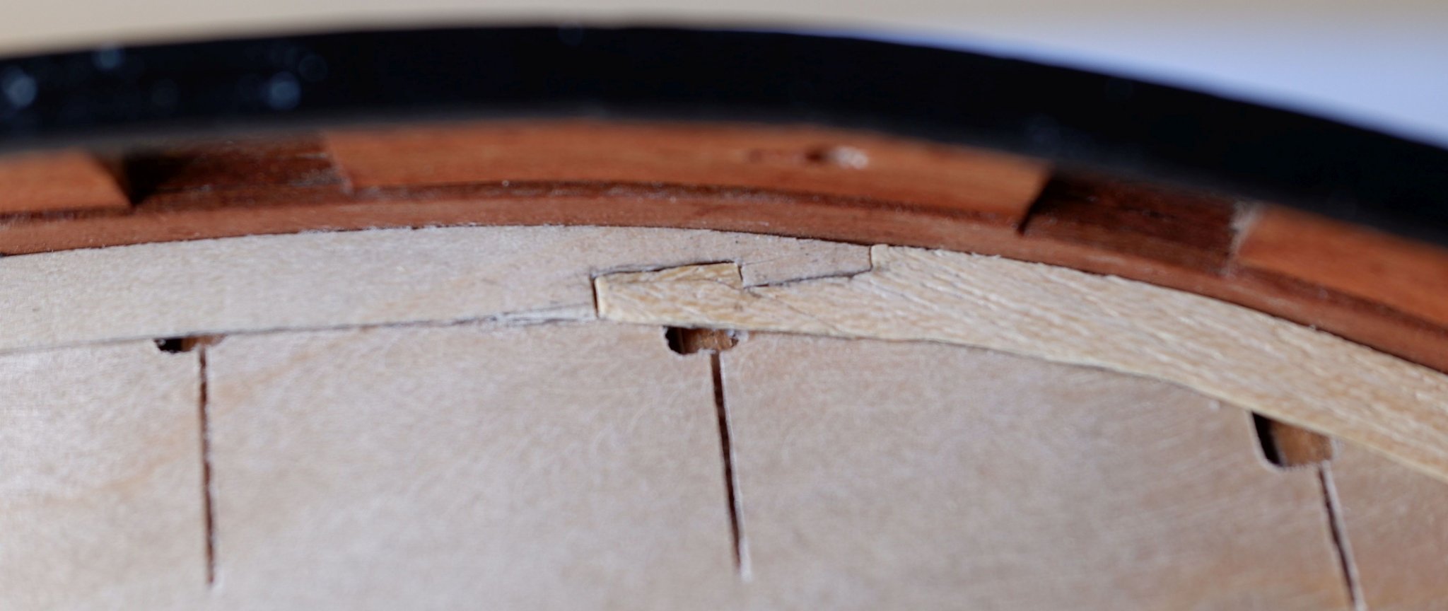
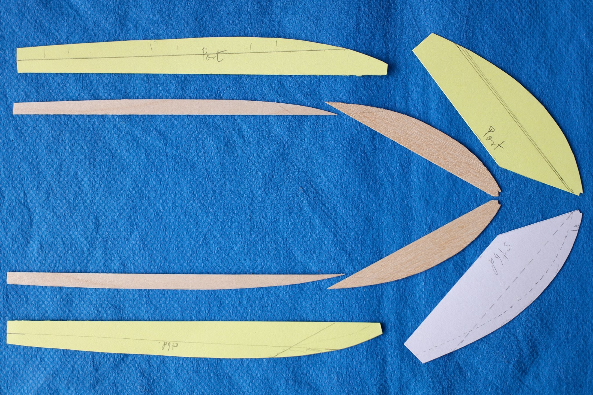
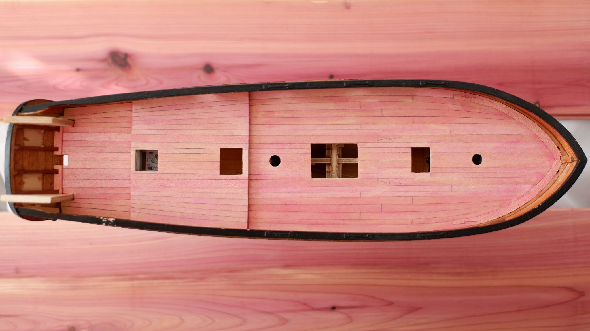
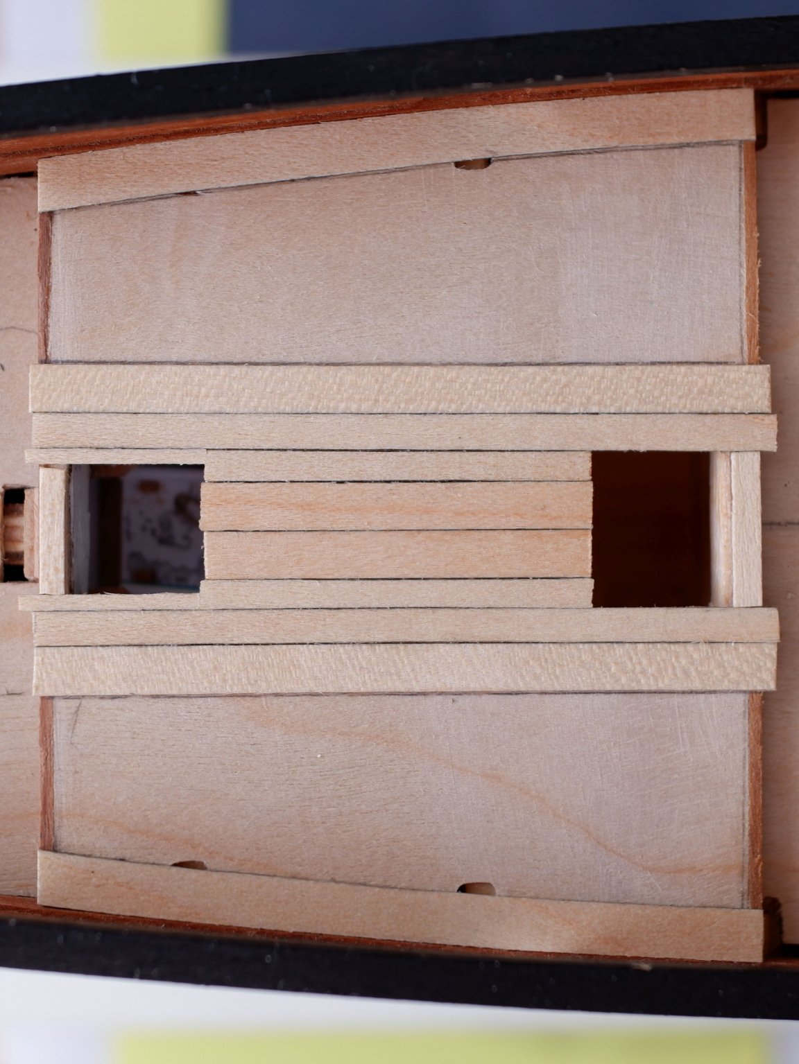
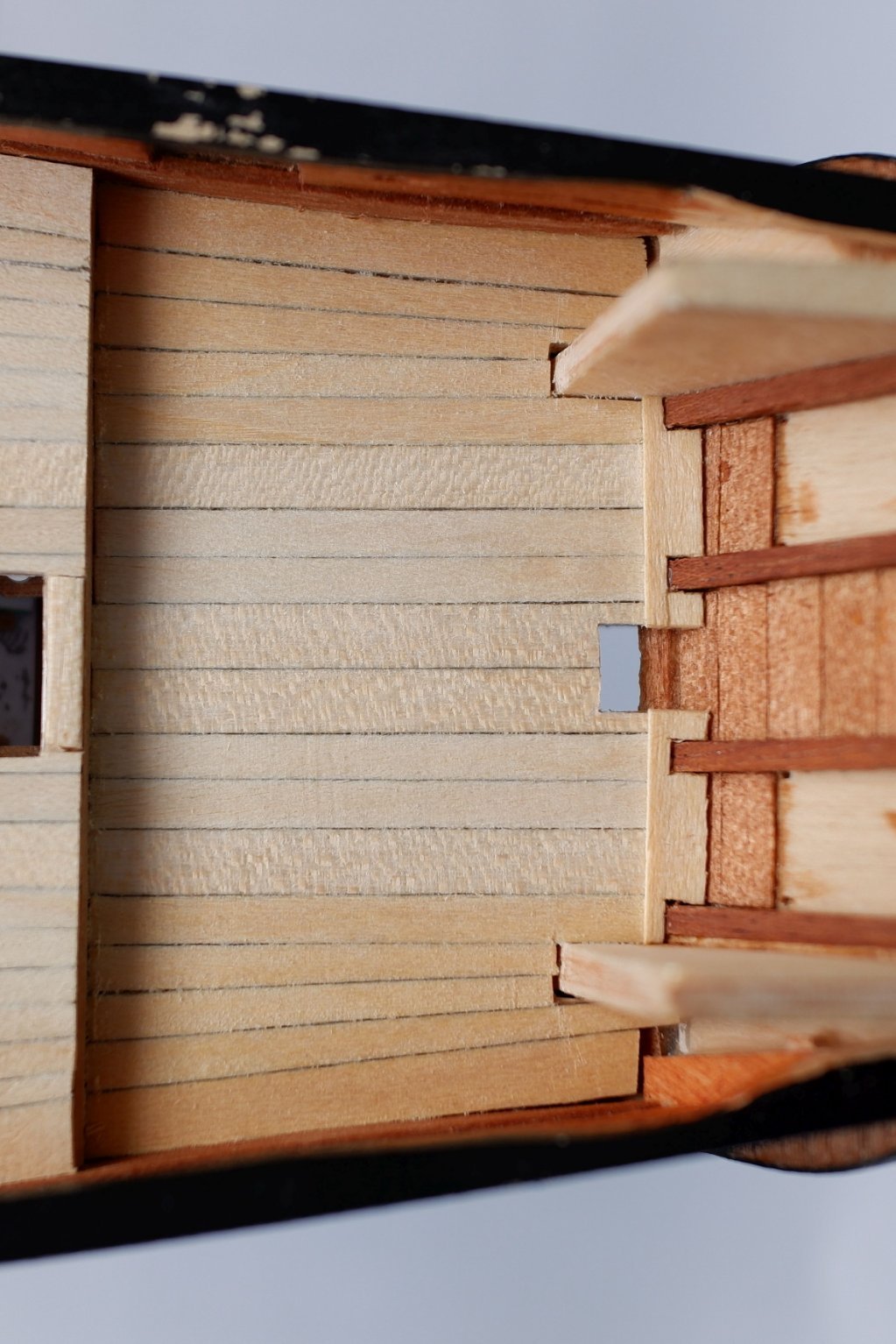
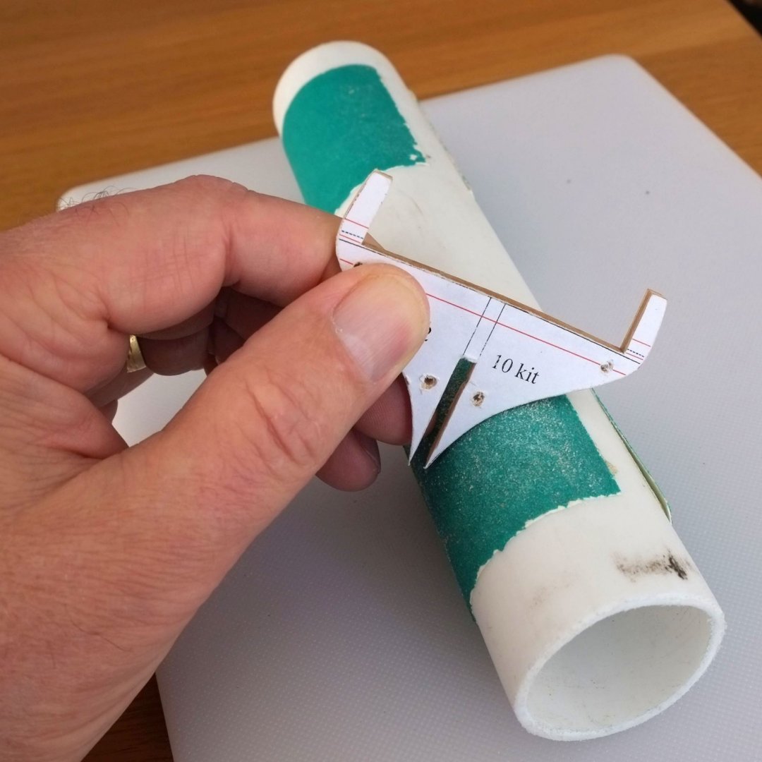
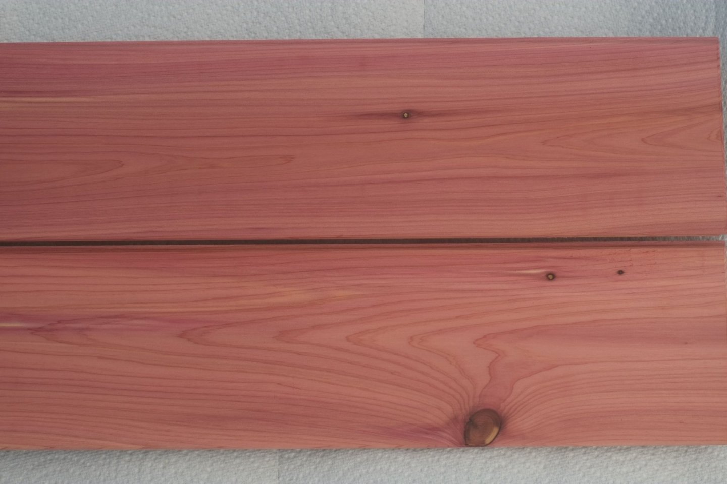
Deck planking finished The fore section of the deck is the largest area and the more complicated one for deck planking. I followed the sequence of waterways with scarf joints, partners down the centre, and binding strakes with false scarf joints. The gaps between them were then filled with other planks. Waterways I made these in two parts. The aft section is almost straight and I spiled it from 6mm wide Obechi to achieve a width of 4.5mm. The fore section at the bow needed a 12mm wide piece of Obechi for spiling. The hooked scarf joint between the two pieces was time consuming and I cut the joint in the aft piece first then marked it on the fore piece and trimmed until they slotted together. It was easier for the second one when I glued ordinary paper under the wood which strengthened it enough to stop accidental splitting. The paper sanded off easily after the joint was complete. Hooked scarf joint in waterway (and a repaired split in the aft piece of wood) The partners and binding strakes were from 4mm wide Tanganyika. The hooked scarf joints in the binding strakes are false and are grooves cut in with a knife point and then filled with pencil dust. The gaps between the partners and binding strakes were filled with 3mm wide planks. The gaps between the binding strakes and waterways needed two straight planks and four planks that were curved and tapered. Three of them had a 'hook' at the fore end so that the adjoining plank would not taper to a sharp point; I did not want to have 'joggling' in the waterway on this model. The joints in the deck planks are over deck beams. When the planks were secured and trimmed and sanded I gave them all a coat of pink wood dye. This changes the image of the schooner somewhat and is quite distinctive. I have bought some Eastern Red Cedar so that I can see the colour of the wood when it is freshly sanded and the next photo shows the deck and the actual wood either side. I think that the pink dye is a close match. Deck stained pink and some real wood of the right species For completeness here is a final photo with a closer view of the deck at the bow. It shows the joints and the 'hooks'. The deck took a long while to complete. My next job will be to copper the hull but I will have a break before then. George


-
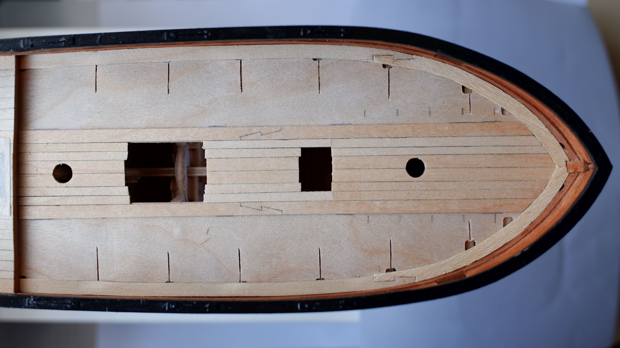
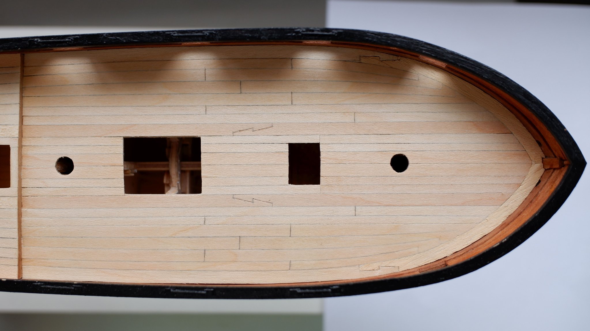
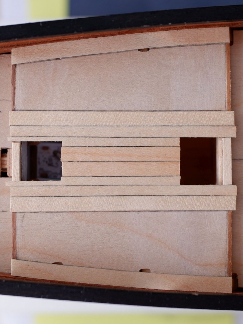
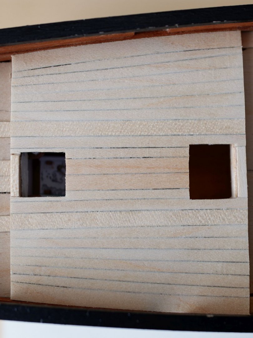
Deck planking I have now completed the planking of the mid section, above the captain's cabin, and the aft section by the transom. The fore section is currently work in progress. The mid section was quite easy and I did it first. I used the 4x0.5mm Tanganyika planks from the kit to lay down the partners either side of the centre line and binding strakes which are further outboard. I set the gap between the binding strakes at 20mm which is the width of the opening for the main hatch. I split some Tanganyika and Obechi to make narrower planks which fit between the partners and binding strakes. A gentle rub with a pencil along the edges of the planks simulates the caulking. There are no joins in the planks because they are not needed. Why add joints when the timbers are long enough? The waterways are a gentle exercise in spiling and I used 6x0.5mm Obechi. The outboard edges were trimmed to fit against the bulwarks and then I used dividers to mark a constant width of 4.5mm. Centre planks, binding strakes and waterways, with narrow planks filling the middle gaps I used tapered planks for the gaps between the binding strakes and waterways. They are 3.5mm wide tapering down to 2.5mm (approx.) and only the outer one has a curve to match the waterway. I decided that the shipwright in Bermuda took the easier option to make them straight and tapered rather than curved and tapered. Trimming the ends and light sanding and scraping finished the job. The aft section was tackled in a similar way. I laid down the partners, binding strakes and waterways (all in 4mm Tanganyika) then filled the gaps with a blend of straight and tapered planks. The aft ends are hidden in the pantry or necessary, or under a plank that runs along the bottom of the transom. This final plank, in two parts, did need some careful cutting to make it fit because the joins cannot be disguised. I could not sand the deck planks because my fingers are too big and used a knife blade instead to scrape them until the deck felt smooth to the touch. Aft section of the deck with the main planks fitted Aft section of decking complete George

-
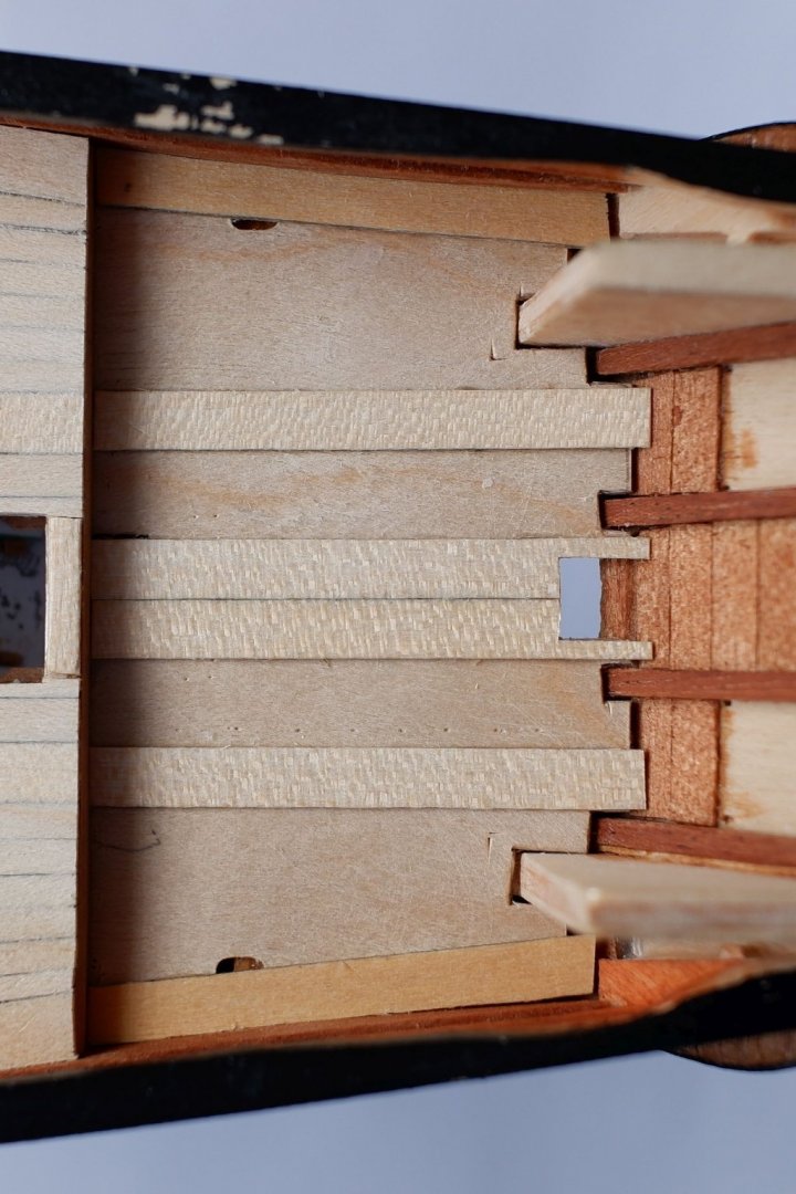
Ian, You are off to a great start here with Sherbourne which is a good first kit. The plywood deck layer that you will be fitting soon comes as a single sheet in the kit but it needs to bend up fore-and-aft and bend down at the sides. This is simply not achievable by bending and stretching the plywood. One solution is to make narrow saw cuts that run above the bulkheads and which allow these double curves to be made. (I recently did this on my 'Ballahoo'.) The extra caution if you do this is to have pins ready to hold down the sides by the bulwarks and some arrangement to press down the centre of the ply piece while the glue sets. Small blocks of wood and elastic bands do the trick. George
-
Bob, Richard, You make excellent points and your timing is superb: I intend to 'copper' the hull of my 1/64 schooner in the coming months and have been thinking about this for some time. I am trying to make the model 'accurate' rather than conforming to model making conventions and this has faced me with some awkward decisions. A model is a representation of reality and will always have some compromises. Some are close to that reality, for example the thickness of a rigging line or the width of a plank. Some are conventions that we accept, for example a ship is stationary in a case and is not actually sailing. The many choices in between these extremes are a balance between accuracy, artisan skill, and art. All of these characteristics are subjective to some extent. Accuracy: In theory we follow Admiralty drawings or information from contemporary models, but we overlay this with our own imagination and desire to represent features that might not actually be visible at a scale distance. There are nails and dents on the edges and face of a copper plate and I would like to nod towards them rather than ignore them. Similarly, I include a few figures on my models to give an indication of scale and I paint the brass buttons on a jacket. Artisan skill: Many models are made to demonstrate the maker's skill and there is nothing wrong with this. It does affect the choice of wood and other materials and sometimes the result looks good but is far from simulating oak planks. Art: I put a few sails on a ship because I like the look, as does my wife. They are out of scale but in my mind the model is bare without them. We all make our own choices because we have different preferences. I have a pack of Amati etched copper plates and might still use them. Or I might make plates from paper in the way that Bob describes. Accuracy is important for me but is it the accuracy of a hull in the water (and the model is definitely dry) or a hull freshly coppered, or in dry dock... Do I want to include weed and barnacles or is that a step too far, for me? A diorama would be treated differently. This model making is something I do for relaxation so I will make my decision at some time soon, and I will not criticize others for their decisions if they happen to be different. George
-
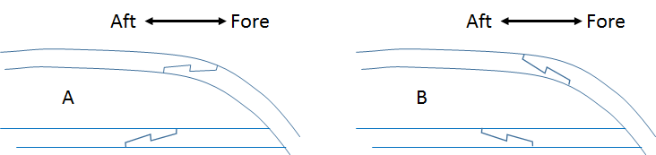
Tony, Thanks for your reply. I think that you have identified a separate question which is about where along a strake you have the scarf joints. The issue of right or left handed, or A or B from my sketch, still remains. For the straight binding strake the position of a scarf is largely dictated by the length of the available wood but the direction of the joint could be at the whim or habit of the shipwright. I imagine that the shipwright would want to minimise the number of joints and so the positions were set by the available wood. If he has suitable compass timber to curve around the bow then he does not need scarf joints between shorter pieces. This results in a stronger structure and less work. For the waterway on my model of Whiting I plan to have a spiled piece around the bow, one scarf joint, and then a relatively straight piece back as far as the step in the deck. The binding strake will have one joint but I have more flexibility about where it goes. I have tried to put myself in the place of the shipwright who has access to local Bermudan cedar and is using his skill and experience to build a schooner. I know that my knowledge is meagre in comparison to the un-named shipwright but wood and engineering principles have not changed. I can claim that what I have is 'reasonable' even though there is little real evidence to justify it. Sod's law says that something will turn up after I have glued the wood down! George
-
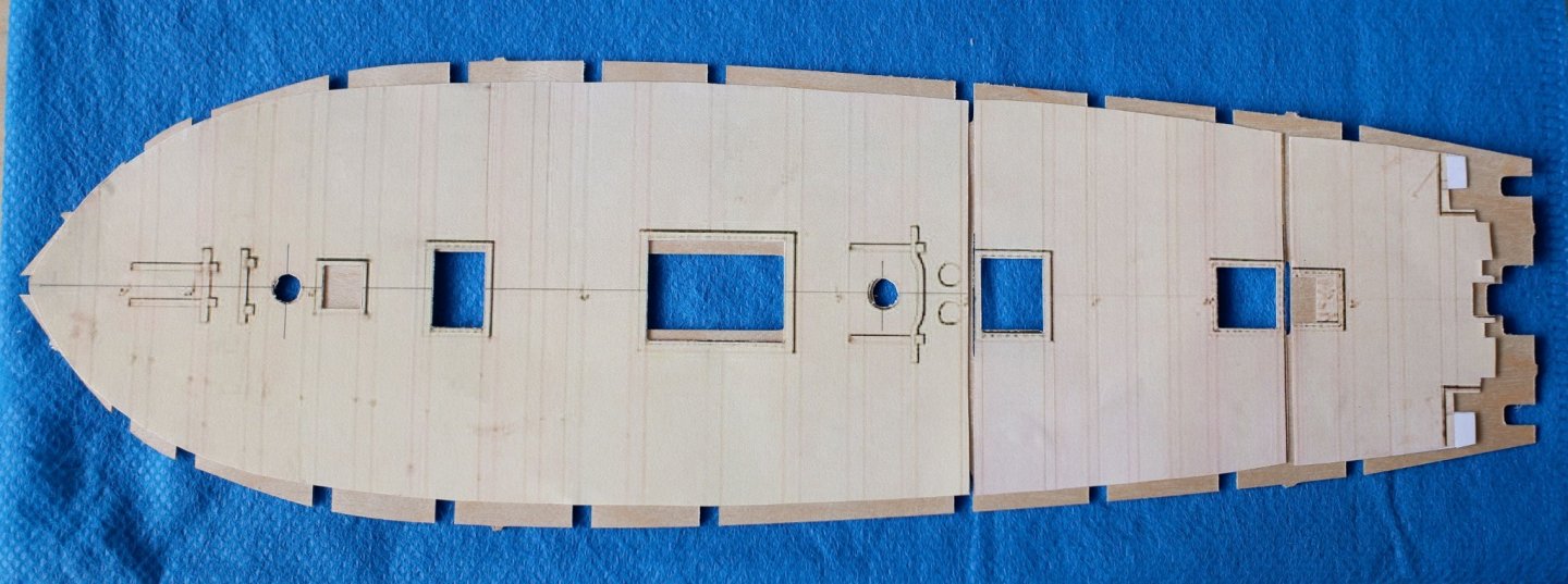
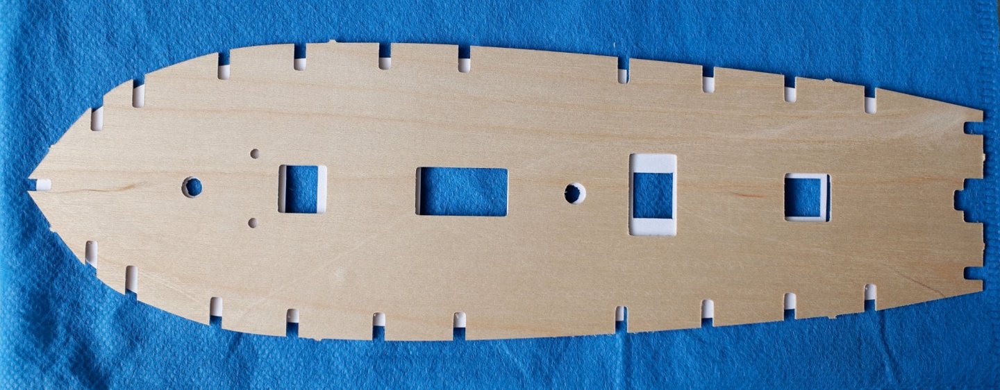
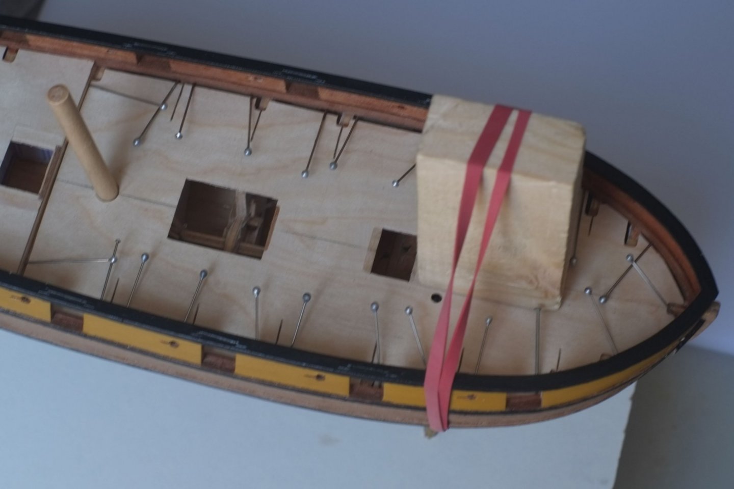
Deck - first layer A little bit of progress to report on the deck for Whiting. I have now fitted the ply first layer which has been fairly straightforward though there were a few unexpected issues to deal with. I printed the Admiralty drawing (ZAZ6117), cut out the main deck plan and separated it into three sections. I glued these to the ply part from Caldercraft. The hatch openings all had to be adjusted. One surprise was that the rear mast did not align with the ply part and after a lot of measuring and rising worry I realised that ZAZ6117 (top view) does not entirely agree with ZAZ6116 (side view) and there are inconsistencies around the rear mast and entrance lobby. Who can you trust? My model so far is based on the side view so I chose to ignore the marked position of the rear mast on the deck plan. I cut slots in the fore section of the deck so that it could curve from side to side (rounding) to follow the top edges of the bulkheads and curve from fore to aft to follow the sheer on the spine. I don't see how the kit can allow any rounding. I stuck it down with wood glue and used pins in the sides and a block with elastic bands to hold it down. It needed more pressure between the two hatches and my thumb grew weary while I waited for the wood glue to grab and hold. One other issue is that the kit is designed for 6mm dowels for the masts, but they supplied quarter-inch 6.3mm dowel which does not fit. This and the similar issue with the spine and bulkheads suggests that someone at Caldercraft thinks that 6mm and 3mm are equivalent to quarter and eighth inch. Close but not the same. The mid and aft sections did not need saw cuts and were held down with pins while the glue set. I continue to ponder about the deck planking and have started another thread about scarf joints. Any help would be much appreciated. George
-
I am with Allan on the home made sanding tools. I have glued sandpaper to the handles of wooden cutlery and then trimmed the overlap. This gives an edge which can get into a corner and a flat area for flattening or reducing bumps. For concave surfaces I have a short length of plastic pipe with two grades of sandpaper stuck to it with double sided tape. It is excellent for work on a hull near the transom. One other tool is at the end of your arm! I do enjoy sanding a hull by hand and feeling the bumps and the force needed to cut through them and any irregularities that you can't quite see. George
-
Druxey, Thank you for your quick reply, appreciated as always. I did not explain my problem properly and have now added a sketch to illustrate the point. I should have done this at the start to make it clearer. The sketch is not an accurate depiction of a hooked scarf but represents the choices I have to make. For the waterway I will be joining an edge-bent plank (aft) to a spiled section (forward) and there is sufficient overlap between the pieces to make either option, A or B. If I choose on aesthetics alone then A looks better to me (at the moment). The join on the binding strake will be handed in the same way as the the one on the waterway just because it looks neater. I enjoy the research on these issues but it is possible to get so engrossed in a search to ensure accuracy that a model does not get finished. Perhaps the only model which can be perfect in all respects is one of a subject which still exists, and the model represents her as she is now. Victory, Cutty Sark and others form a small band but the vast majority of ship models are reconstructions based on best available evidence. Sometimes we rely on informed guesses. (I have just found and enjoyed the thread you started about research.) George
-
Many drawings and references show scarph (scarf) joints on the deck planking for the stronger, more important planks. The waterway by the bulwark is one, the binding strake outboard of the hatches is another. The shape of a hooked scarf joint is well known and the proportions for the lengths of different sides can vary. A paper by Karolak et al describes many of the variations on scarf joints Karolak scarf joints.pdf. Current use in boat building are described in a short article by Souppez https://www.woodenboat.com/strength-scarf-joints. I guess that around 1800 in the Royal Navy or elsewhere there was a conventional way to draw and cut the joint so that it is not too long or too short. Does anyone have a contemporary description of the relative sizes? I think back to learning how to make a mortise and tenon joint at school where the join is one third of the width of the wood. There must have been something similar, though more complicated, for a scarf joint. My second question is about left-handed or right-handed joints. Drawings in three books I have all show that the aft timber extends farther forward on its outboard edge; the fore timber that goes into the joint extends farther aft on its inboard edge. Was there a conventional way to align the scarfs or was it the choice of the shipwright? I have not yet found any contemporary evidence. I will continue my searches on Google and ask for advice from the wise people who have looked at this before. If there is no evidence anywhere then I will simply choose a joint shape that looks good. George
-
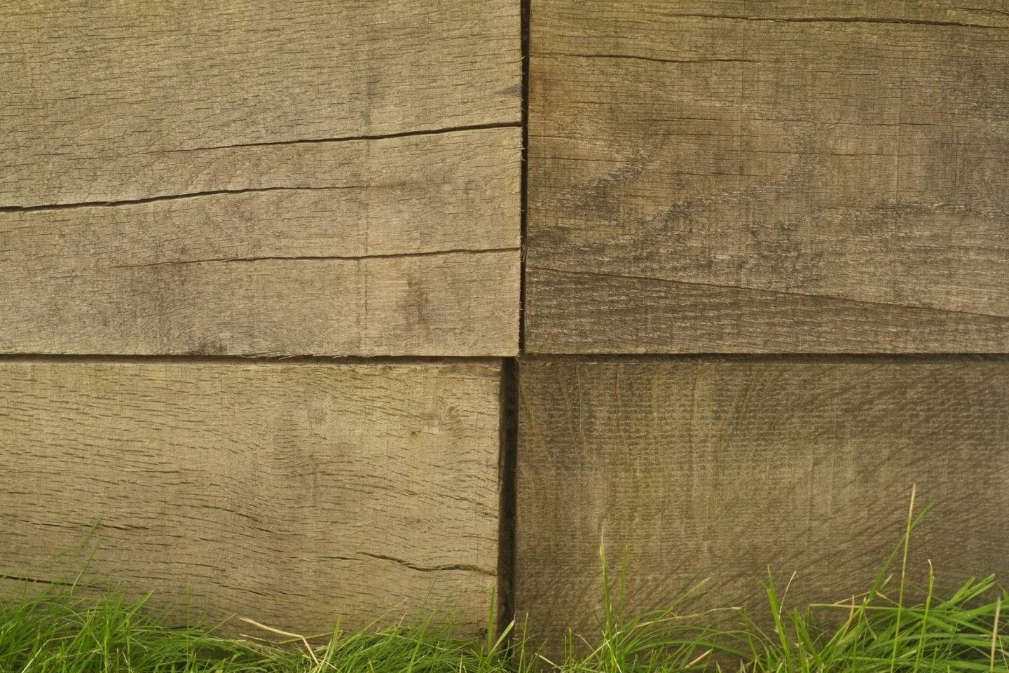
It all depends on what you mean by 'best'. Other similar discussions approach the subject from an aesthetic or artisan direction where the aim is to show your skills to advantage. There is nothing wrong with this and it can lead you to any number of hard woods that have a fine grain. It becomes a matter of personal preference as to how much grain you want to see; for me I like to see a boundary between parallel planks but not a huge difference. These woods also hold a corner so that when you want a sharp edge it can be achieved by cutting or sanding and you don't get rounded edges. The colour is also a matter of personal preference and there are some fine models with yellow or red or white tints to parts of the hull. An alternative aspect of 'best' is realistic. A model at a viewing distance of one foot is equivalent in some ways to a real vessel at 48 feet or 64 feet or more, depending on your scale. At this distance the grain becomes invisible and a painted finish could (whisper it) be just as 'good'. But the convention for ship modellers is to have a wood finish and we would only paint a surface to look like wood if the model was made of plastic. So what does a real, wood surface look like? I came to this issue and found this thread when considering the deck on a Bermuda built schooner from 1805. The deck would be holystoned every day so the surface would be fresh, sanded wood. On most Royal Navy ships the deck was, I think, fir or a similar softwood (help me here Allan or someone else). Even if it was oak the surface would be pale and a 'white' wood would be suitable on a model. Jotika in their kits supply Tankanyika for the deck or you could use obechi or lime/ bass or holly. The schooner I am making was built from the local wood in Bermuda which is variously called cedar or juniper. It is now rare from over exploitation but Eastern Red Cedar from the USA is meant to be very similar. Some might call me obsessive, but I have now bought some of this wood and the shipping and import costs equal the cost of the wood itself. (I will use the wood to make the base for a display cabinet.) It is pink. In the photo below it is resting on some white paper. It is most definitely pink with white sapwood. The deck on my model schooner will be pink. My plan is to use the Tanganyika planks from the kit and stain them with a pink dye. Leaving the deck we come to the rest of the hull which was not sanded every day and the wood would age with time and sun and salty water. Old wood in my garden or elsewhere tends to be grey unless it is varnished or treated. It does not seem to matter what variety of wood it is, it goes grey with age. The next photo shows four pieces of oak which have been in the open for three years. I would guess that a typical, oak built ship would be a similar colour unless you want to portray it as being wet in which case it would be much darker. I do not know how the Eastern Red Cedar will age but I have already built the hull in walnut which is a bit darker than this oak sample. A question for other modellers or sailors. Do you have photos of a real, untreated wooden hull that we can use as examples? George
-
Gary, That's a good point about a 'steam scuttle' which is a new term for me. I had not included the full drawings of Haddock and the cooking range or stove is forward of the ladder way; the chimney hole is next to the fore mast. The additional structure aft of the ladder way is, I would guess, just to support a sliding hatch. The deck drawing does not show ventilation holes there, or anything else for that matter, so we are back to speculation. I imagine that the cook would want to keep the hatch at least partly open to let out the steam and to provide light so he could see what he was doing. George