georgeband
-
Posts
307 -
Joined
-
Last visited
Content Type
Profiles
Forums
Gallery
Events
Everything posted by georgeband
-
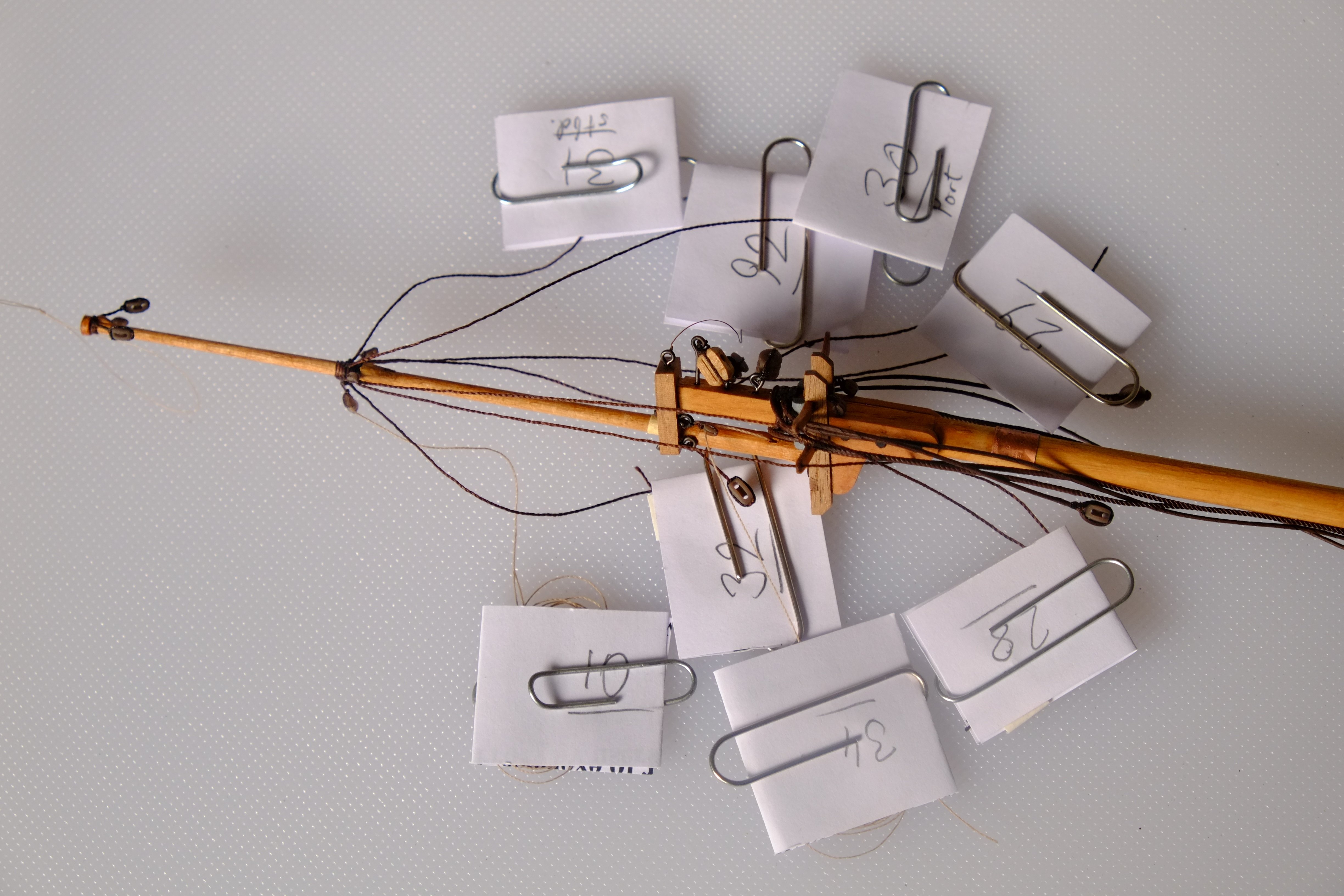
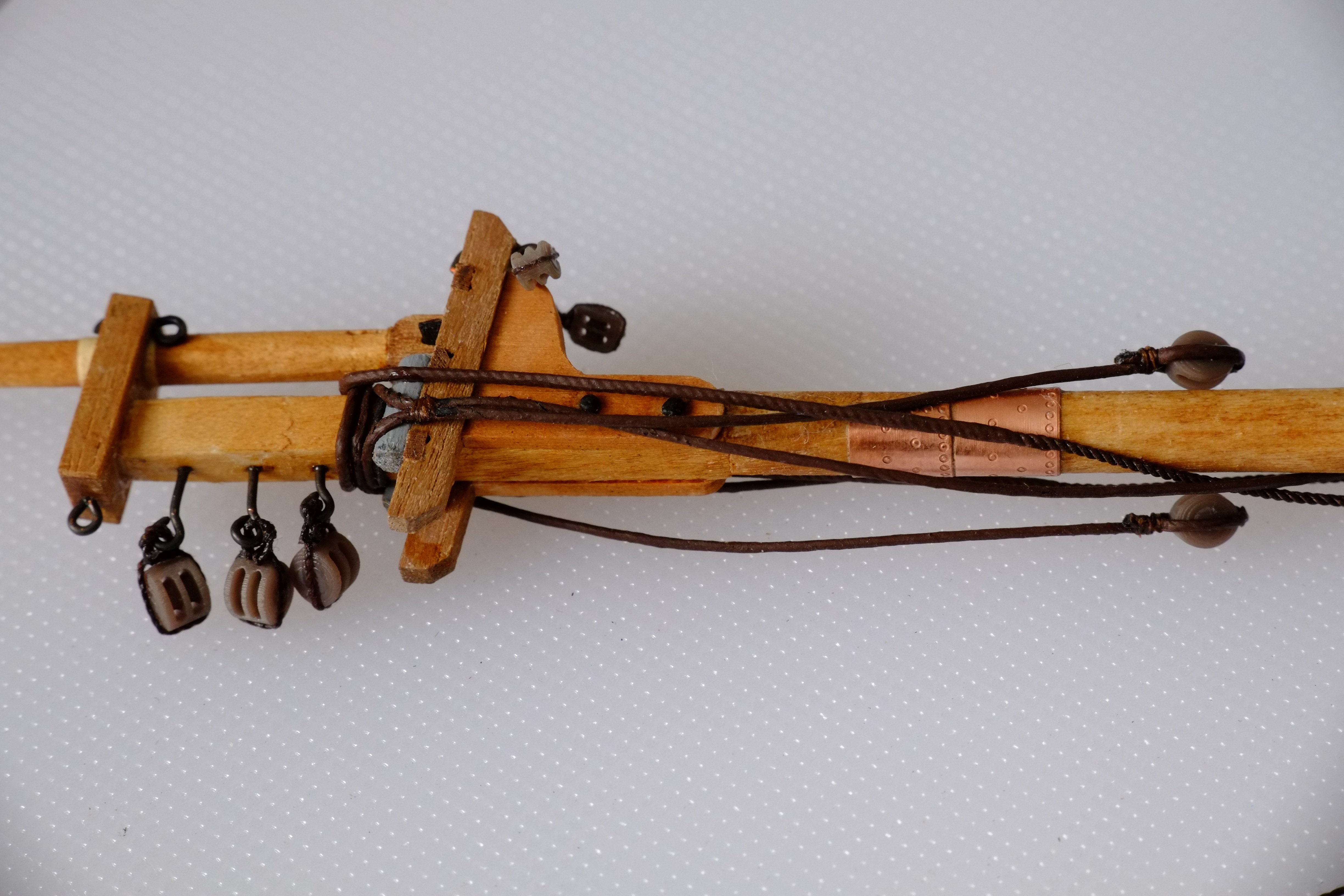
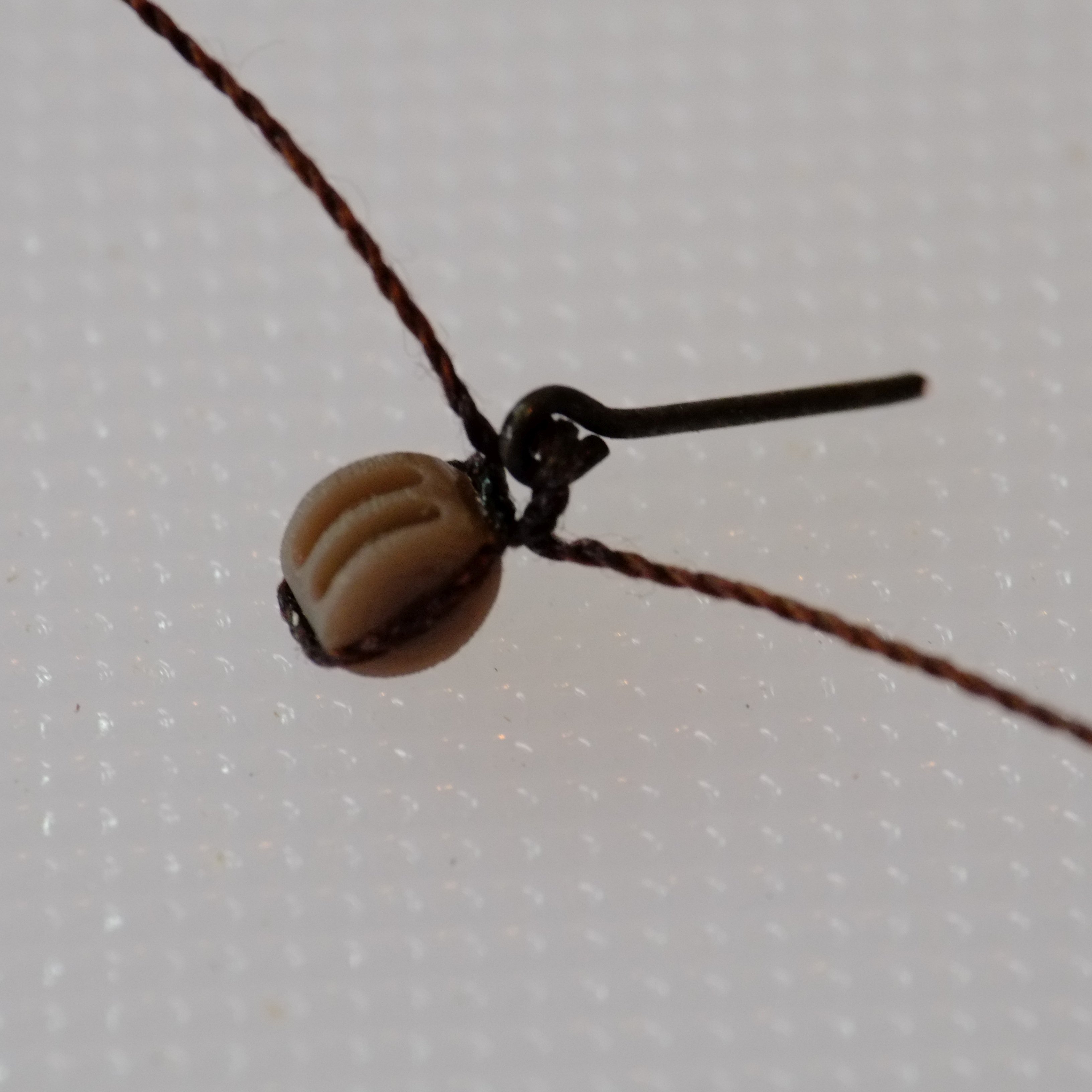
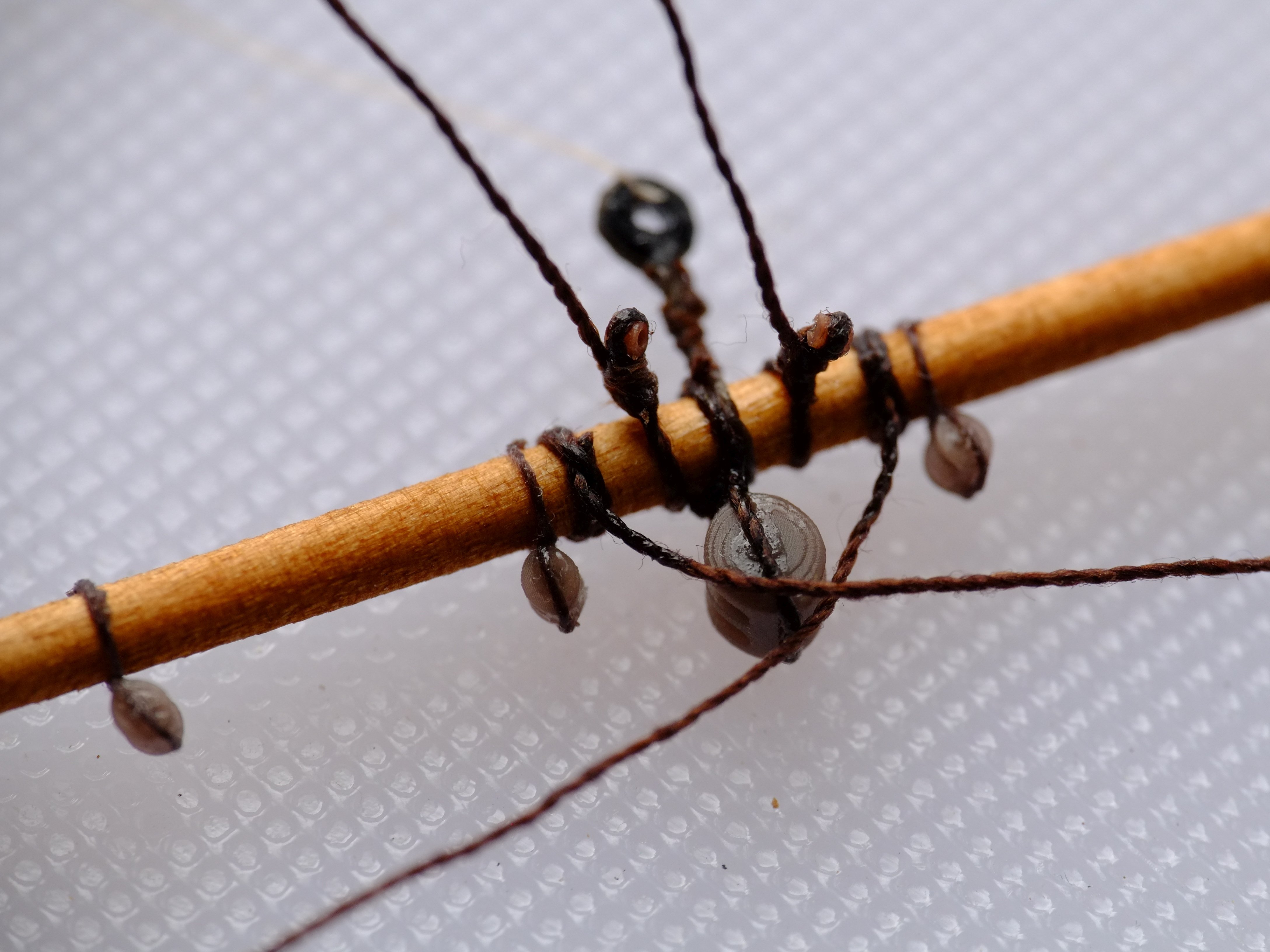
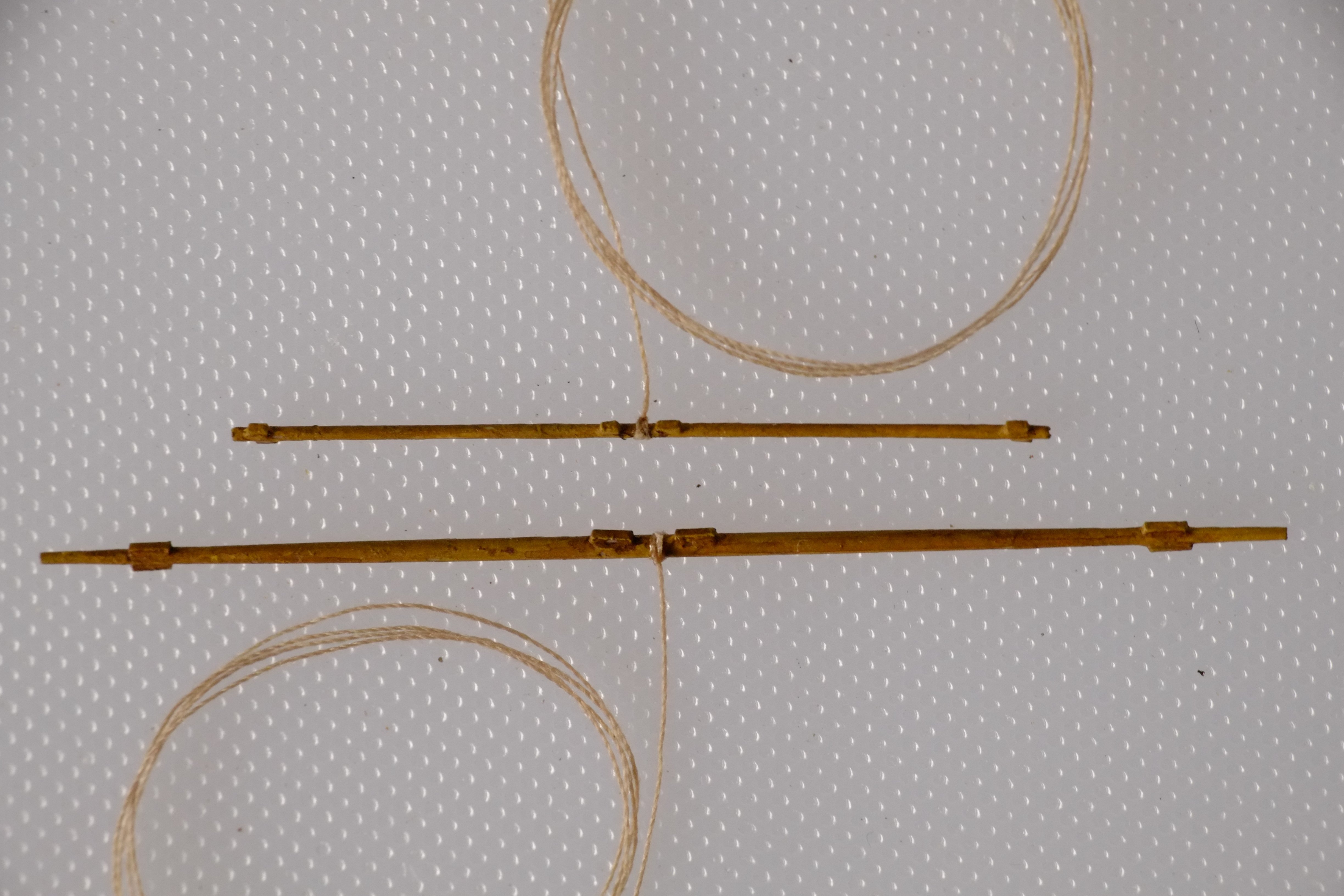
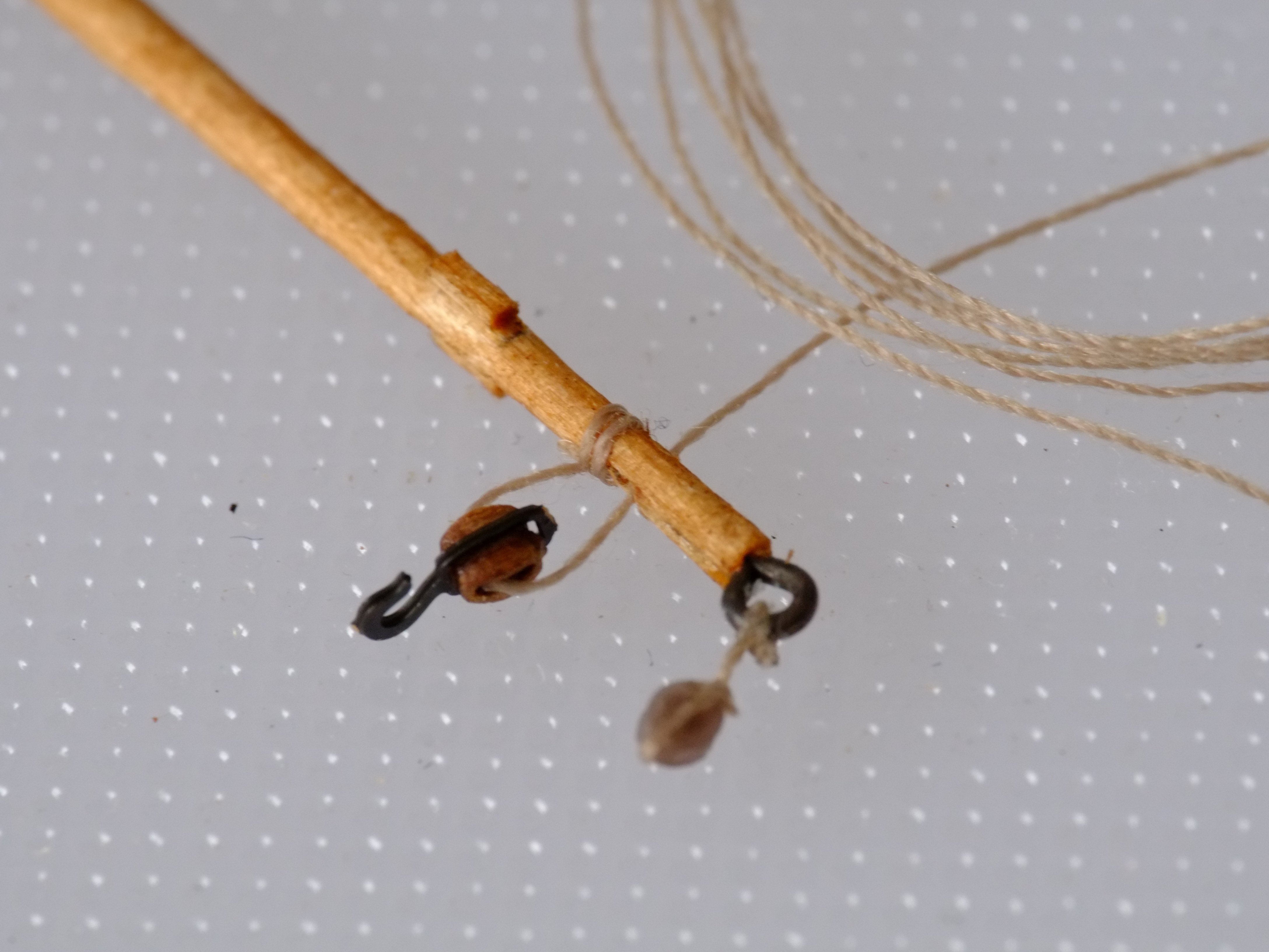
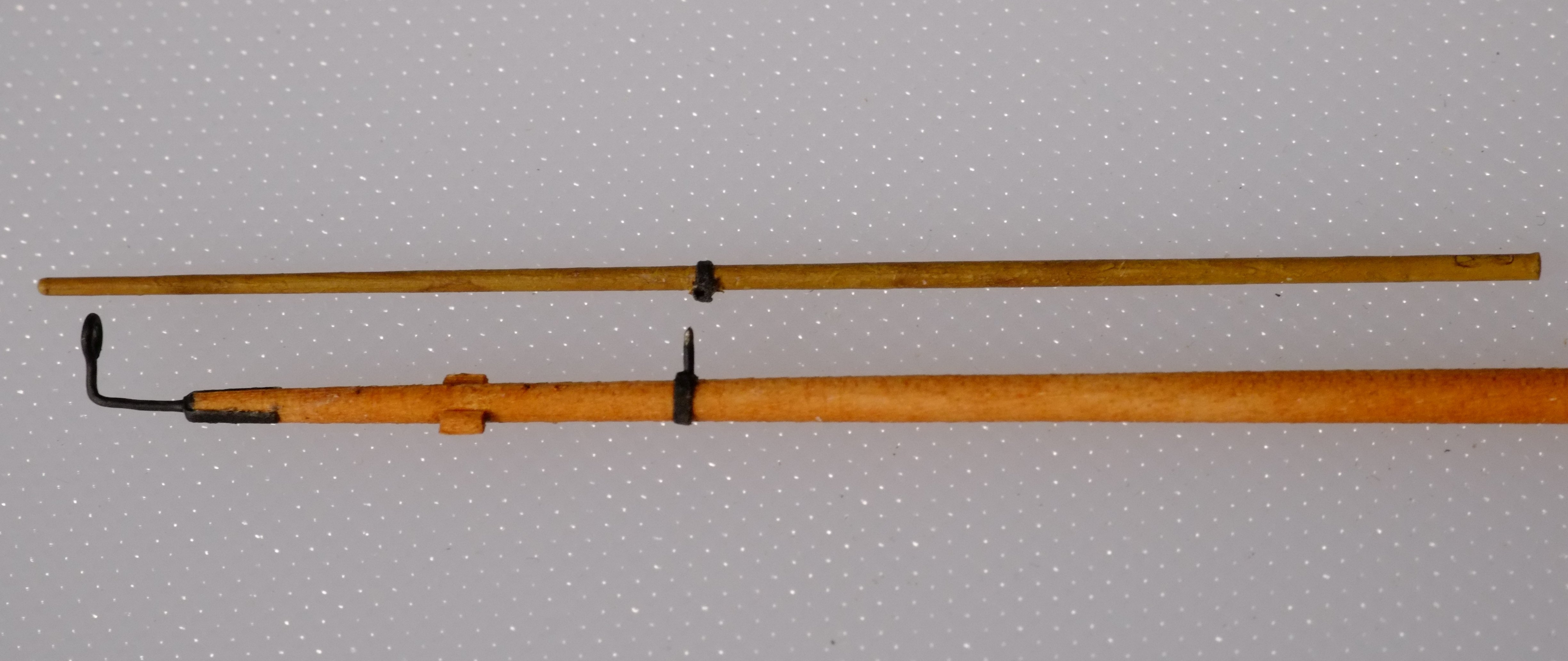
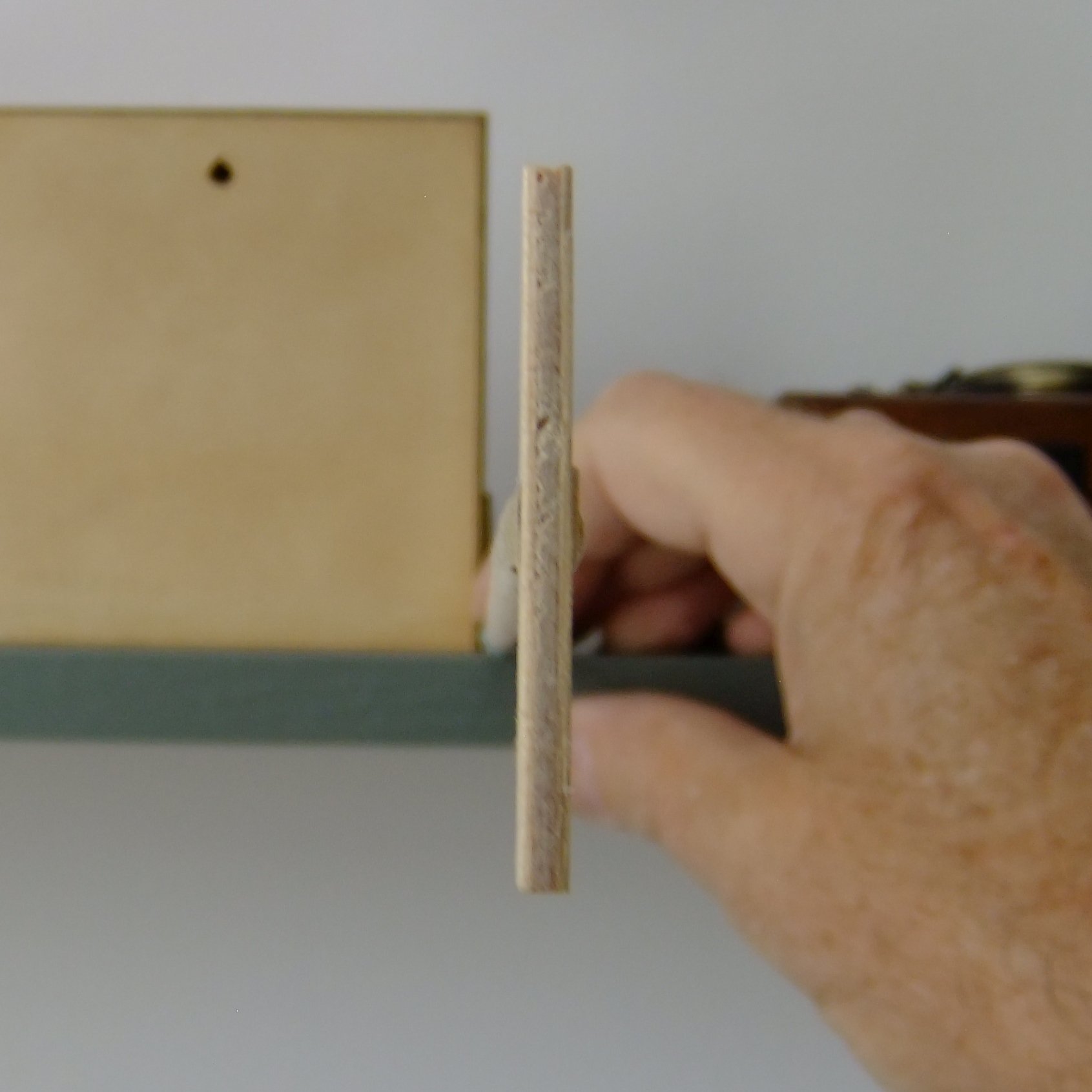
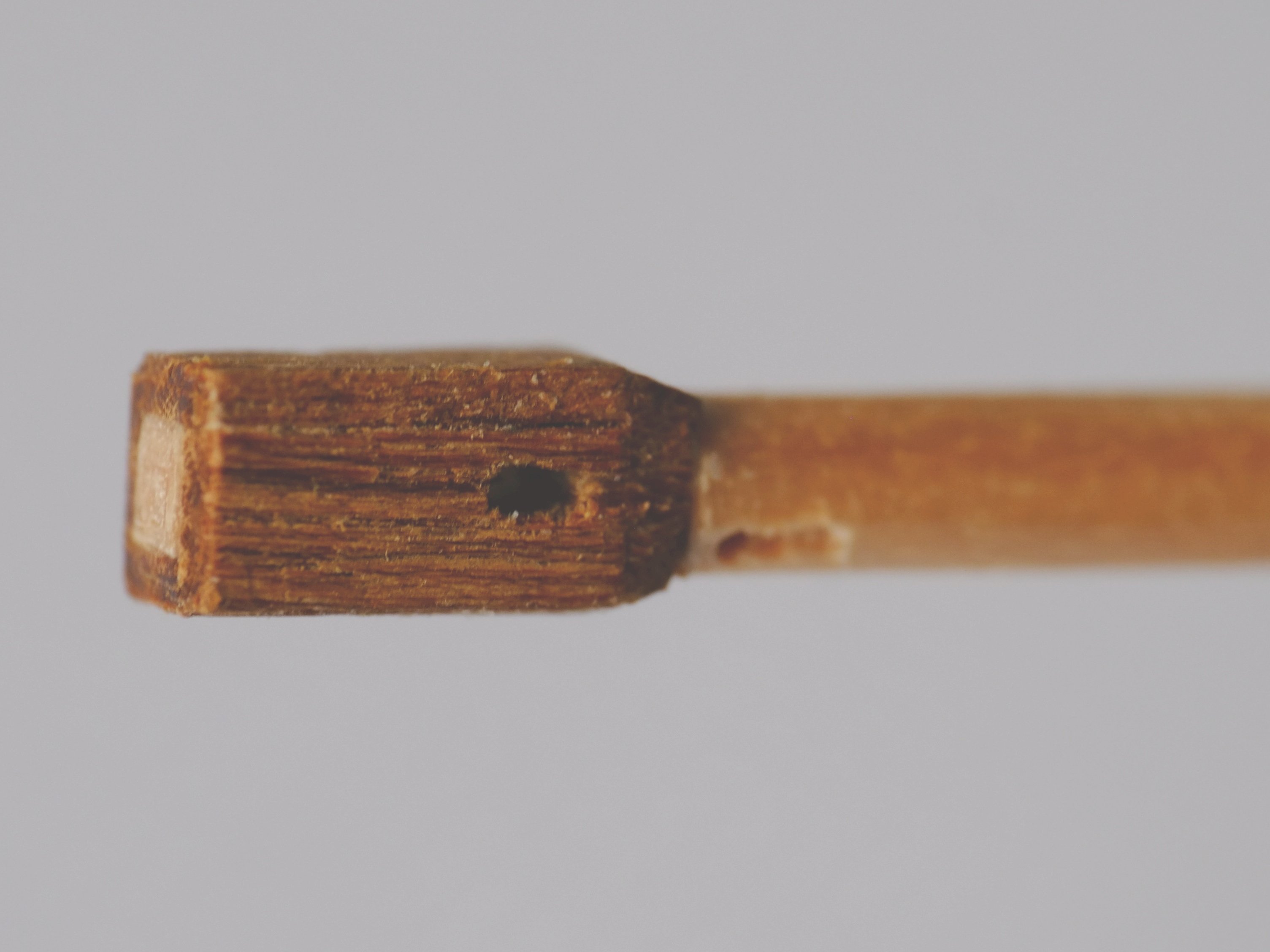
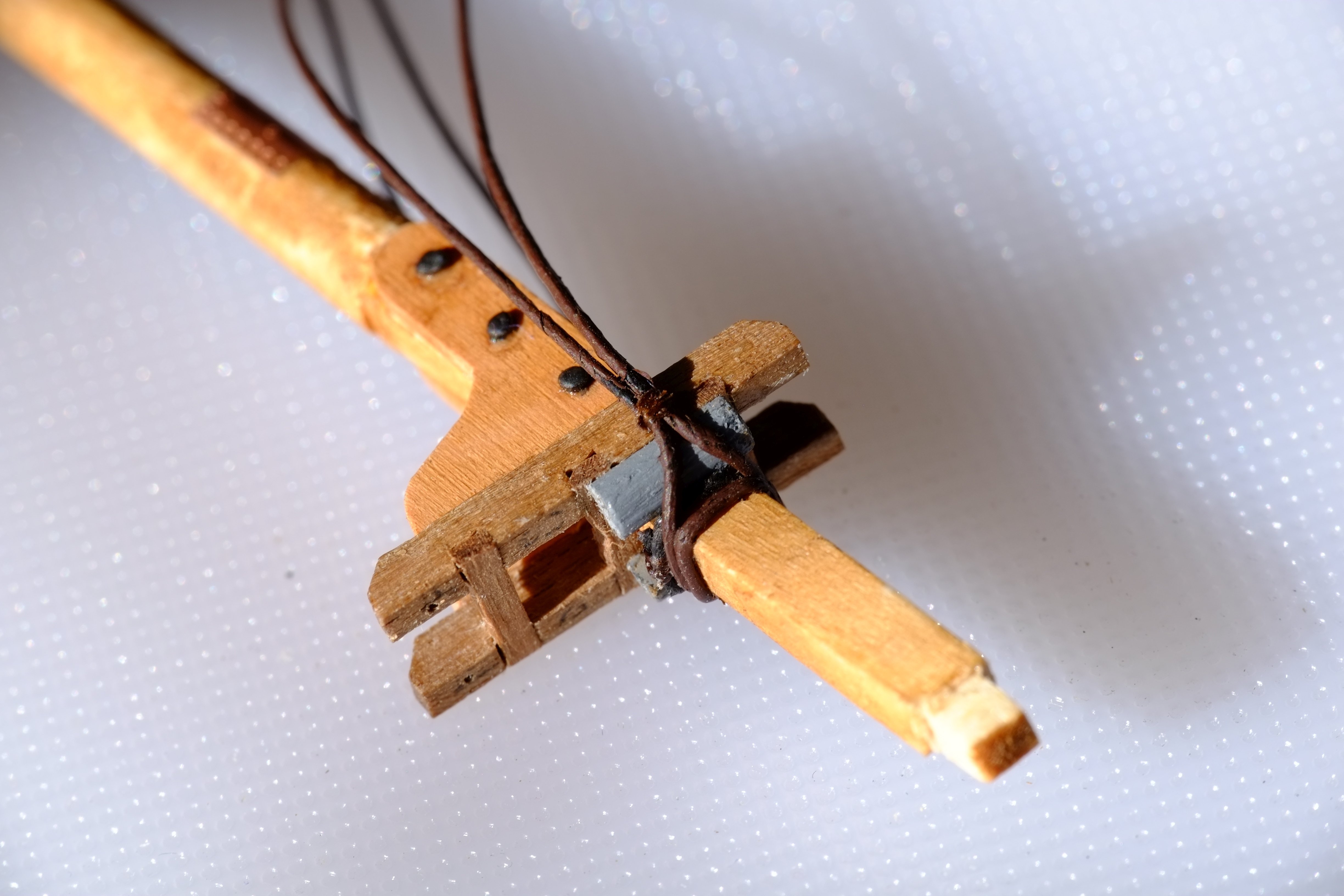
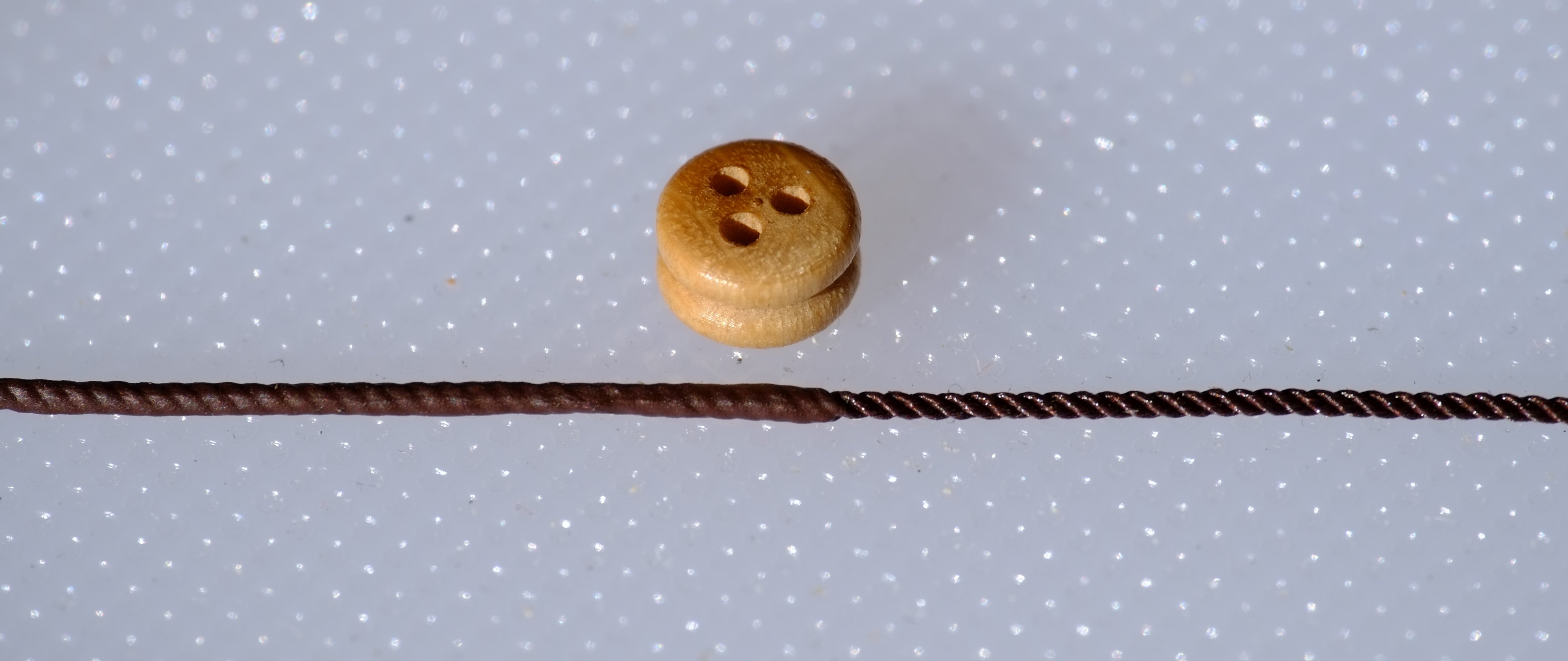
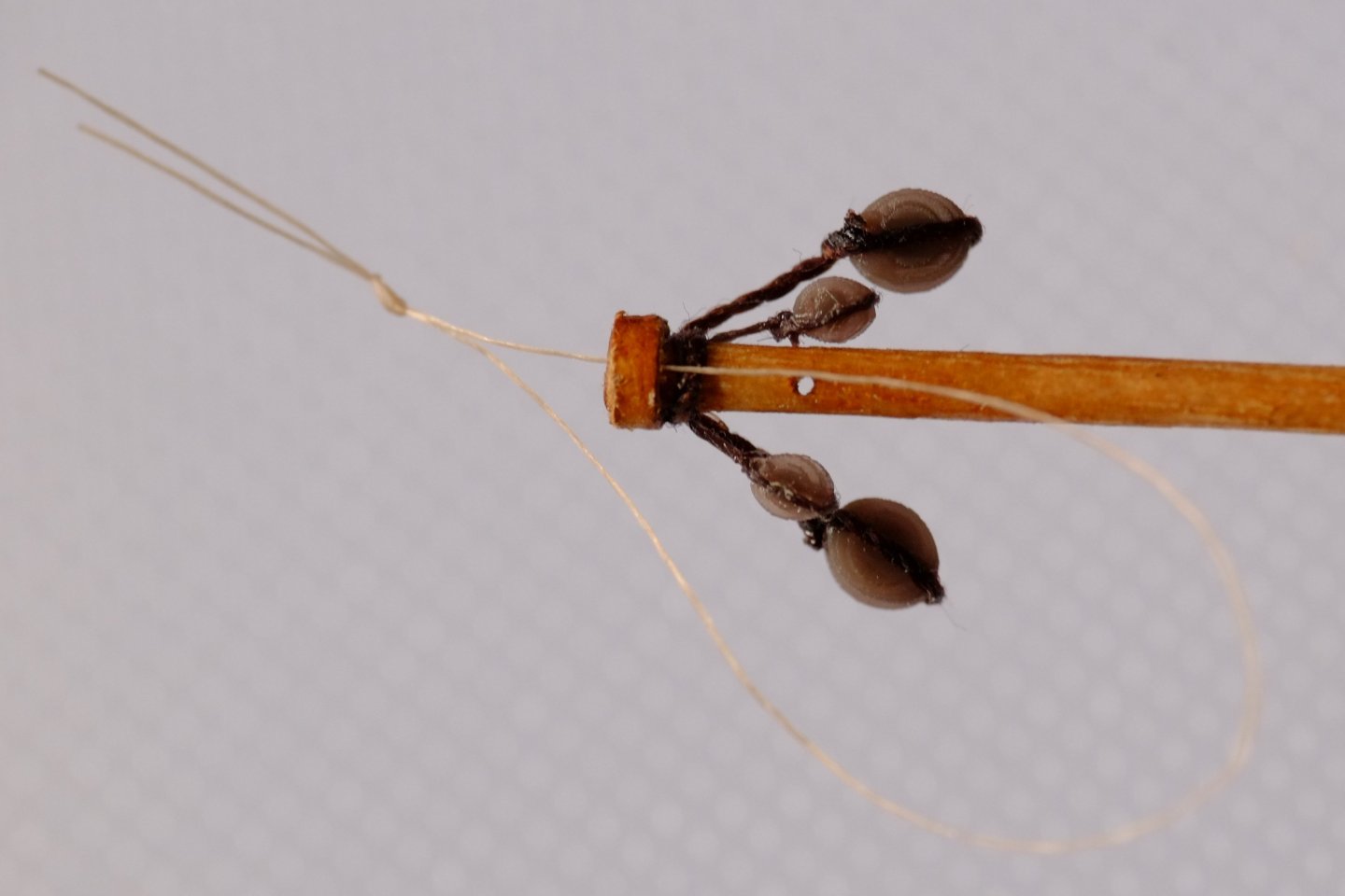
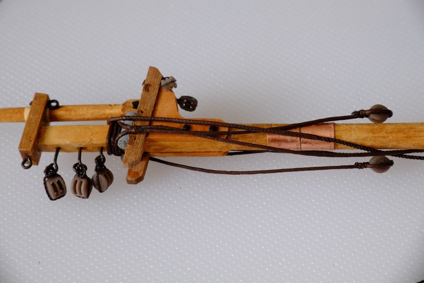
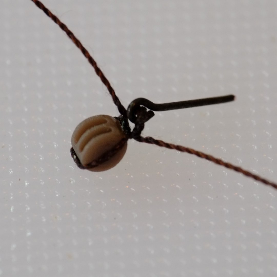
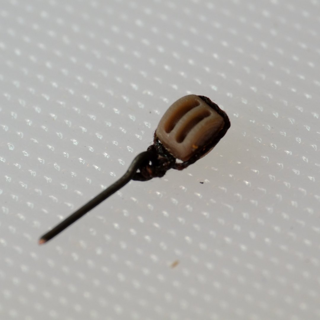
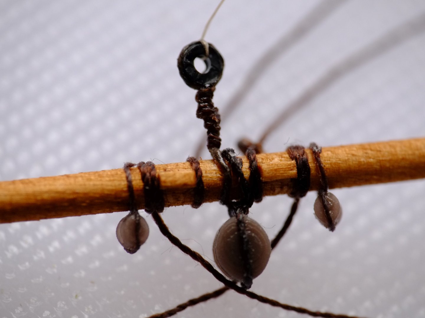
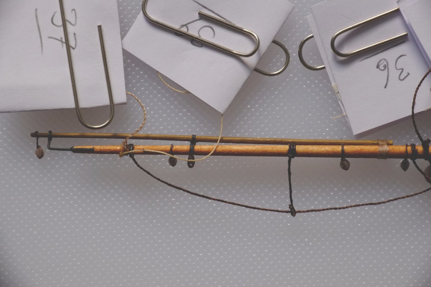
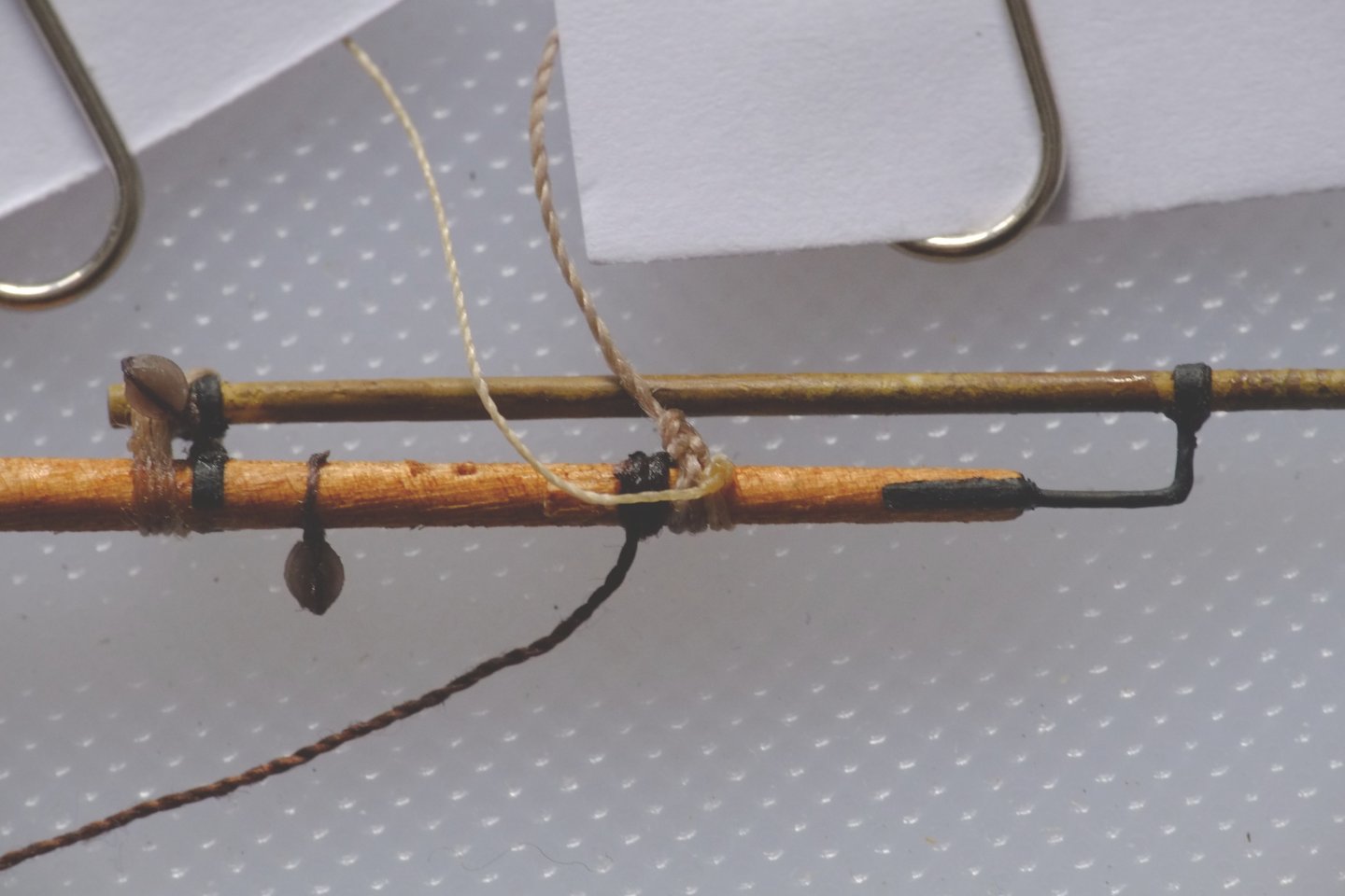
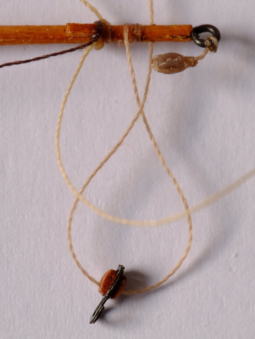
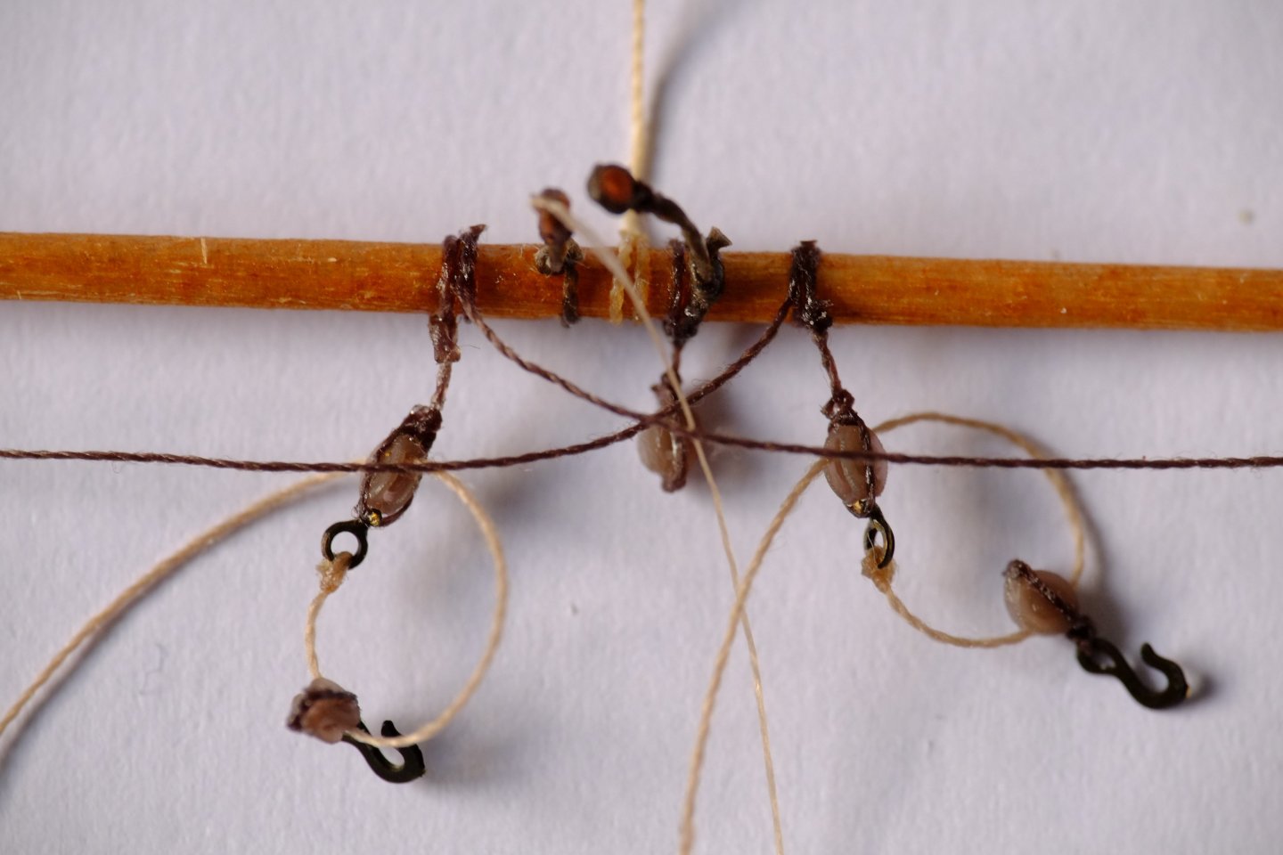
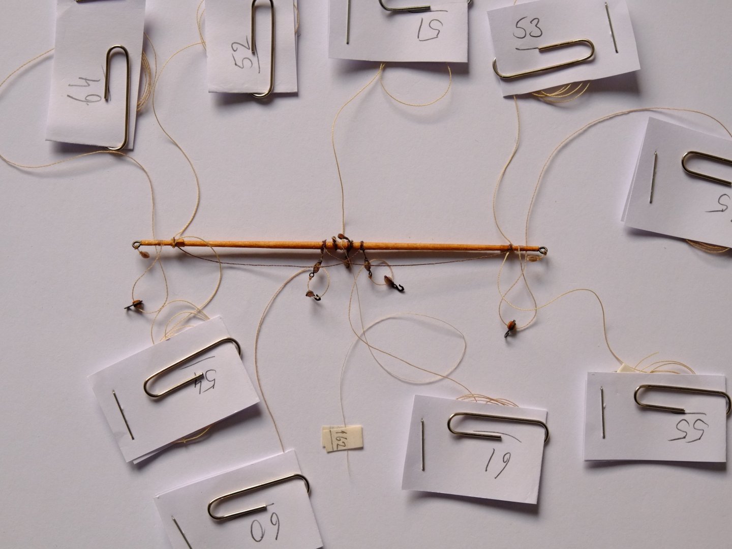
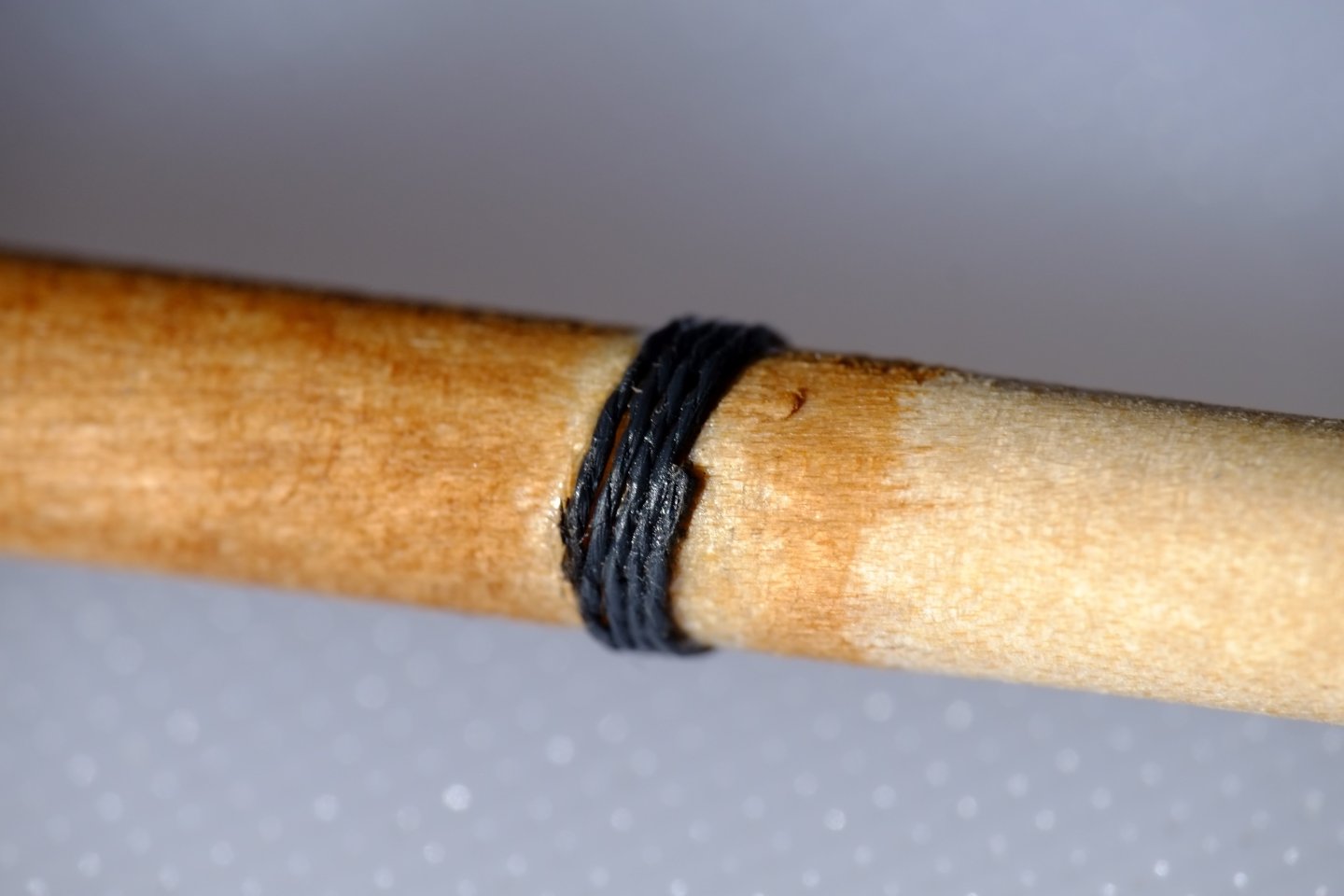
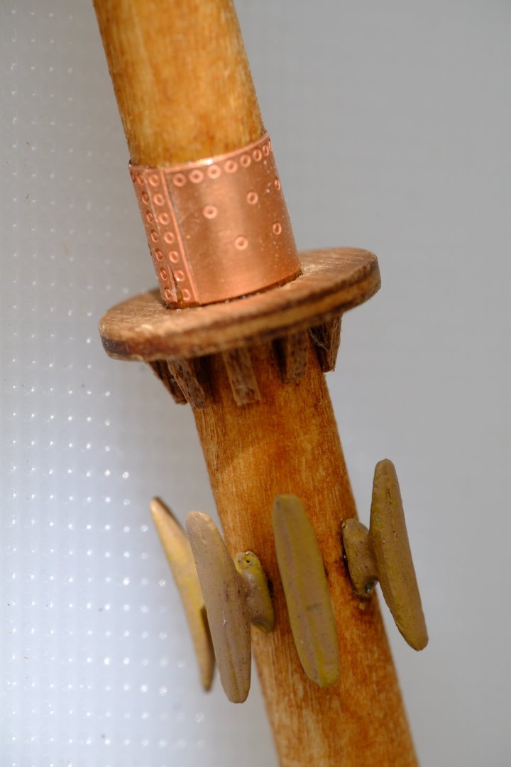
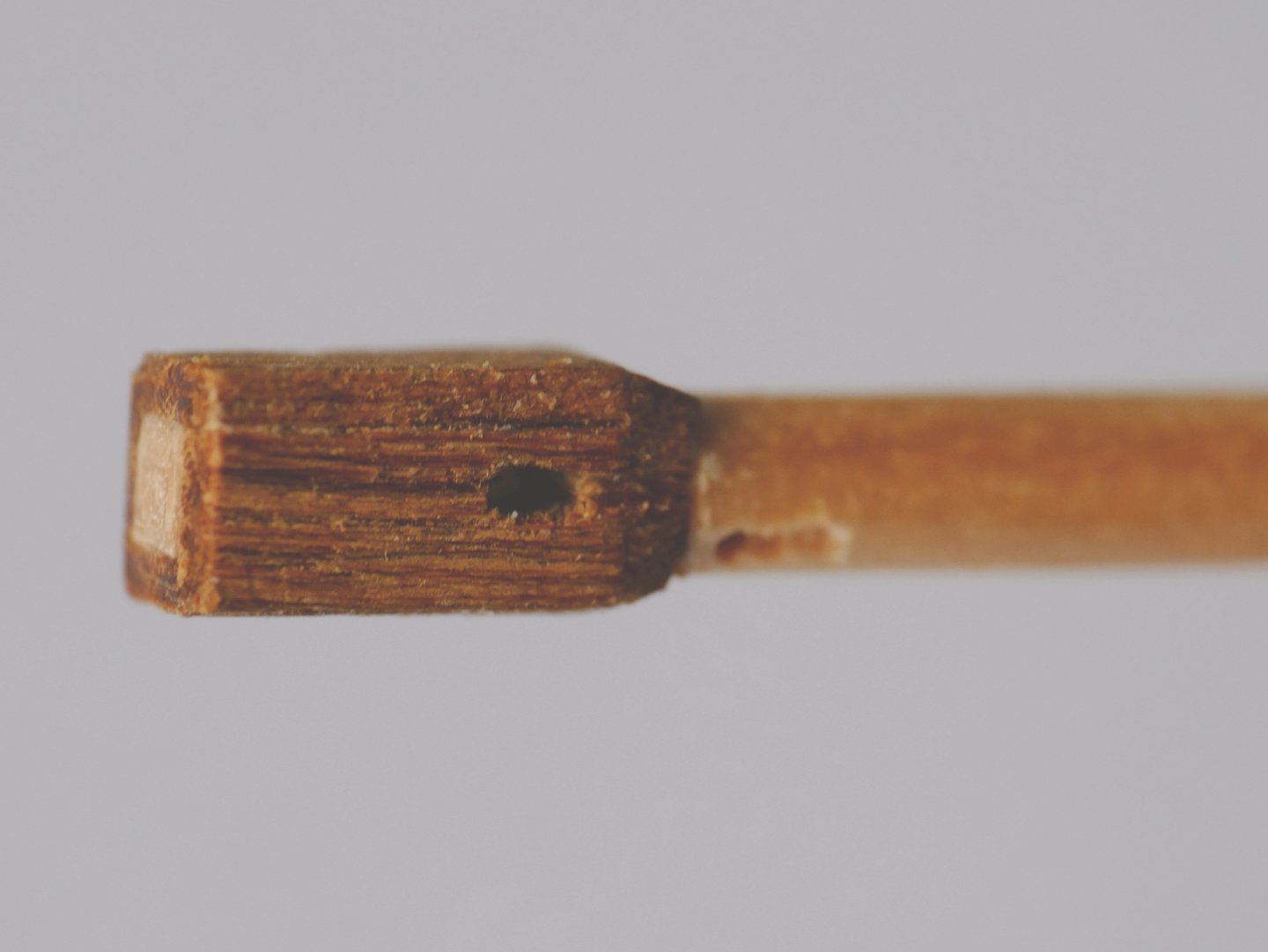
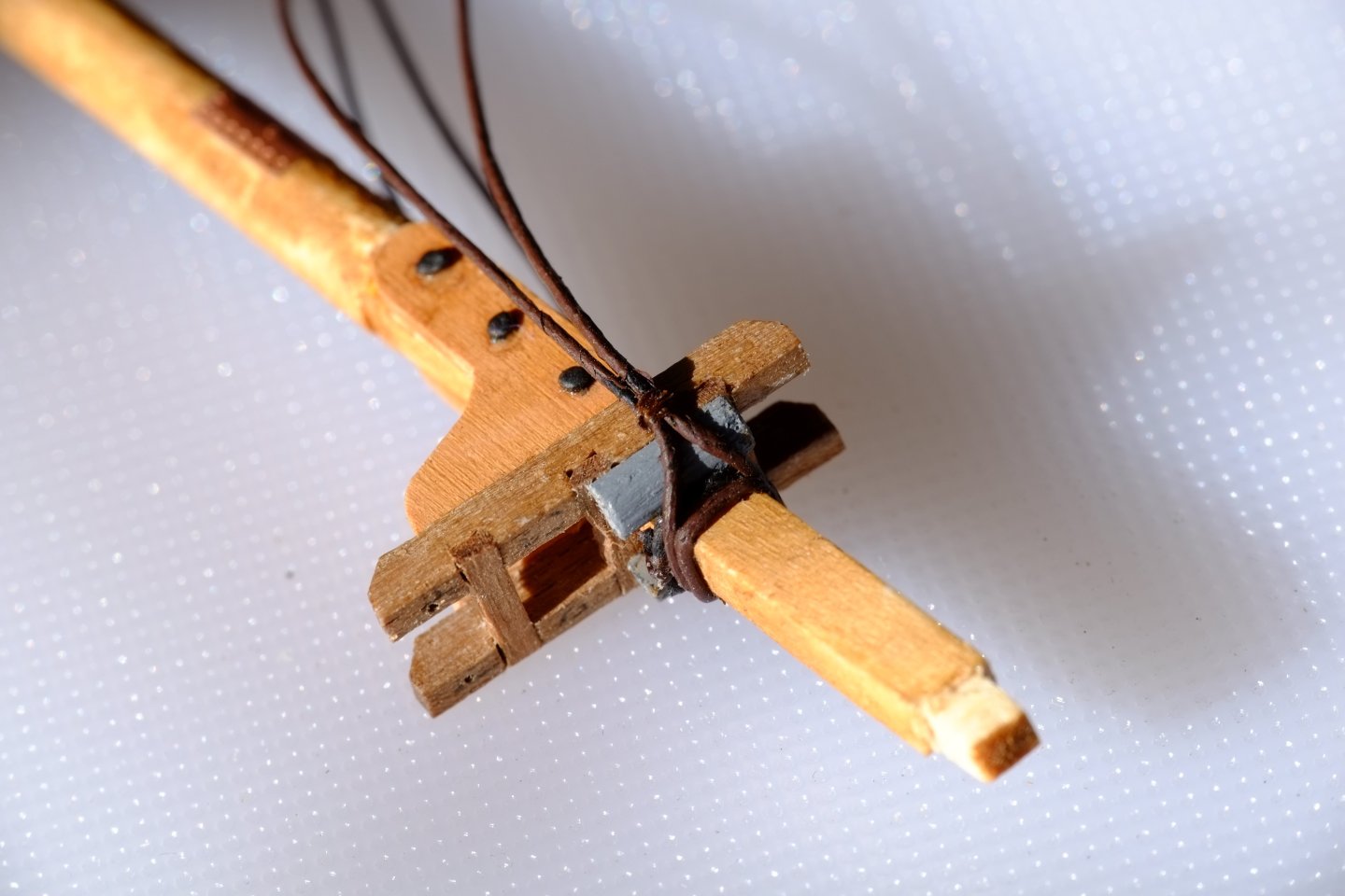
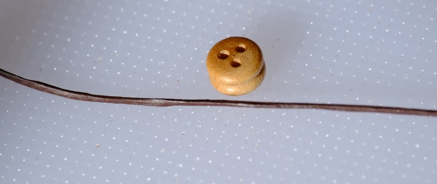
 Pre-rigging the masts Both masts have had blocks and lines tied on wherever this can be done. It is tricksy work with one small stick on the workbench and would be so much more difficult when the masts have been stepped. The picture below shows the fore topmast with everything fixed to it. The blocks are mostly from Seahorse and I have been trying various arrangements for strapping them to give an eye, or a pendant, or to trap a running line or a hook. The little paper pockets contain coils of rope and the paperclips prevent the coils from sliding out. I had to undo a serious tangle before I decided on these pockets. Lines that are loose through the blocks will be rigged later, some when the yards are attached and the assembly is still on the workbench, and some when the mast is swaying and I have to poke a thin thread into a tiny hole. The second picture shows the tip of the fore topmast. It has four blocks, a sheave hole and a hole in the truck for a signal halyard. I have tied a loop of fly tying thread through the hole in the truck to show me where it is. The main mast is generally similar to the fore mast but has less rigging on it. This picture shows the blocks on the mast head, mast tackle pendants with blocks seized into the ends, and more copper on the mast. I added a full-length copper plate below the existing half-piece so the crew do not have to get the height of the gaffs precisely right. I did not like the dull, oxidised finish on the original plate and gave them all a polish and a coat of Renaissance wax. The two blocks below the trestle trees, forward, are for bracing the square yards on the fore mast. The last pictures show how I formed an eye on a Seahorse 4mm double block and put it around a copper wire eye. These blocks are so big that I do not need special measures to hold them! The 2mm single blocks are a different matter and a lot is done by touch. Glue Gutermann extra strong polyester thread to one face of the block, then bring the thread round and glue it to the base and the other face. Tie the two ends together with an overhand knot. Seal the knot with glue, leaving two tails sticking out. The tails are about 1mm apart and are parallel to each other. Feed both tails through the copper wire eye from opposite sides. Put the tails through the thread bight to wrap them around their partners and thicken the thread eye. Carefully apply glue to harden the thread without gluing the copper eye. I put a wipe of superglue on a pin; a visible drop is too much and will flood the structure. The thread eye can be shaped by squeezing and pushing it with fine tweezers. Trim off the thread ends. Repeat for two more 4mm blocks then try it with 2mm blocks. My next task is to draw plans for the gaffs and the main boom. I might include the yards for the ringtail sail and the main topsail and the boom for the ringtail. It all depends on what I can achieve before my dear wife takes us away on a holiday, or the grandchildren want help with something. George
-
Phil, It sounds like your model mimics reality quite closely. According to Lever the truss with its tackle going up functions as a preventer yard sling, in case the actual sling should break. His words for figure 238 are 'Should the Slings of the Yard give way, these will act as preventer Slings, and hang the Yard until sufficiently secured'. My checks on my belaying plan have paid me back by revealing an error. Nothing critical but I have been diverted for a couple of hours to look up the references. In my working days I organised verification and validation trials and 'success' was measured by the number of mistakes that I could find. It could be soul destroying and I preferred to work with designers to help them get their designs right. George
-
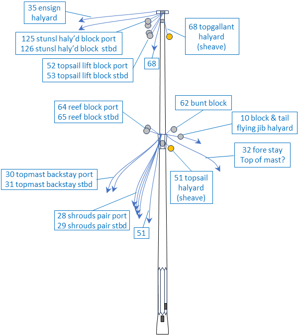
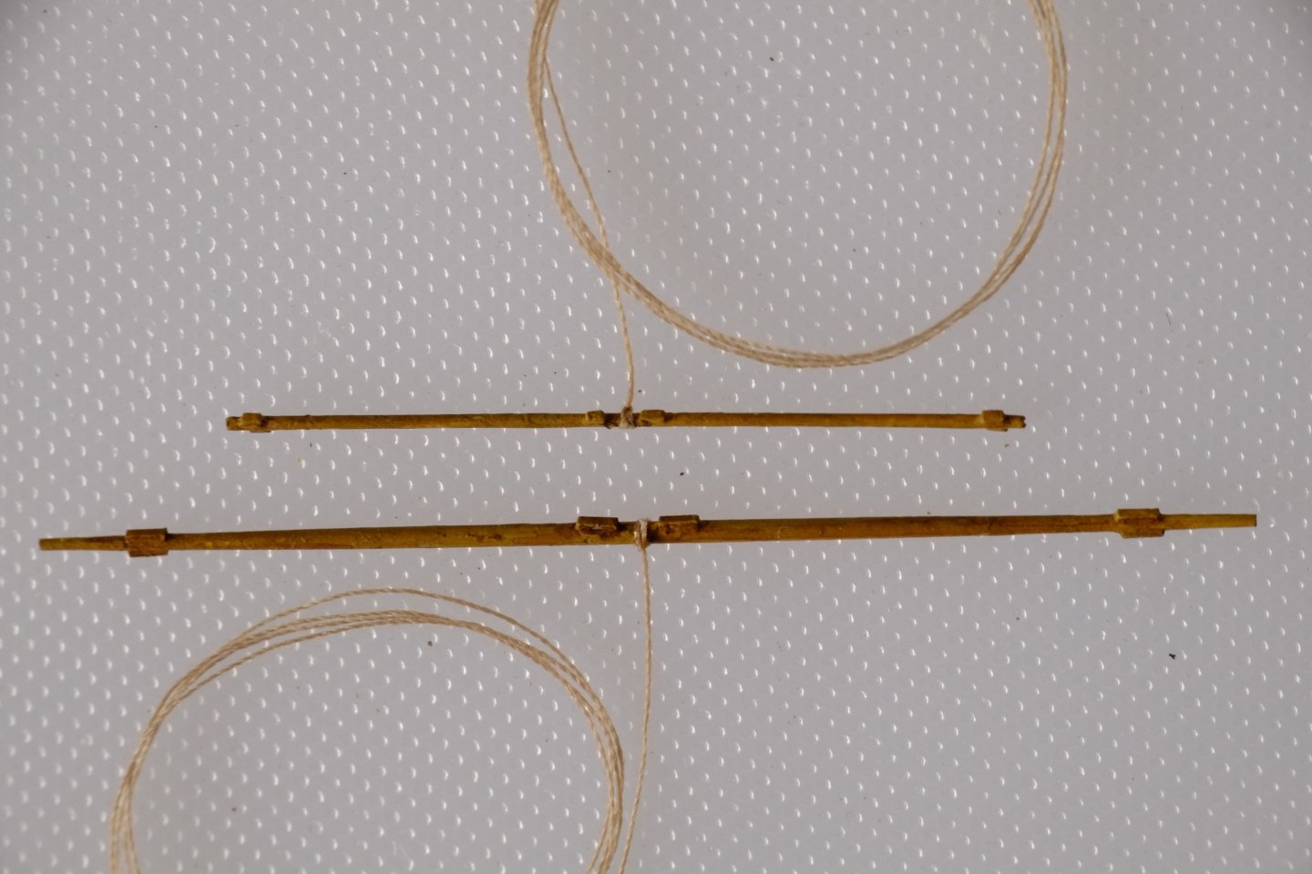
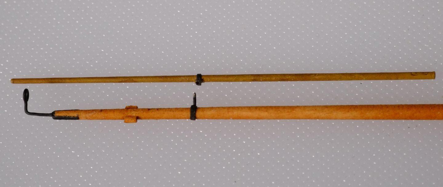
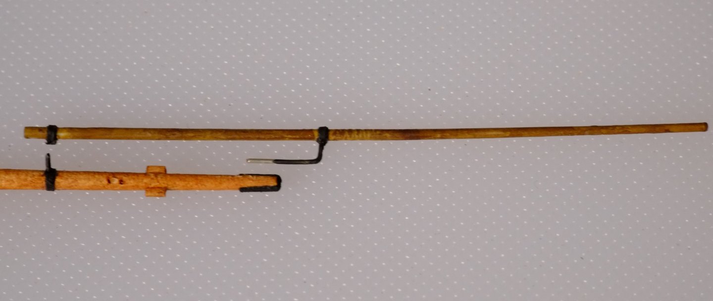
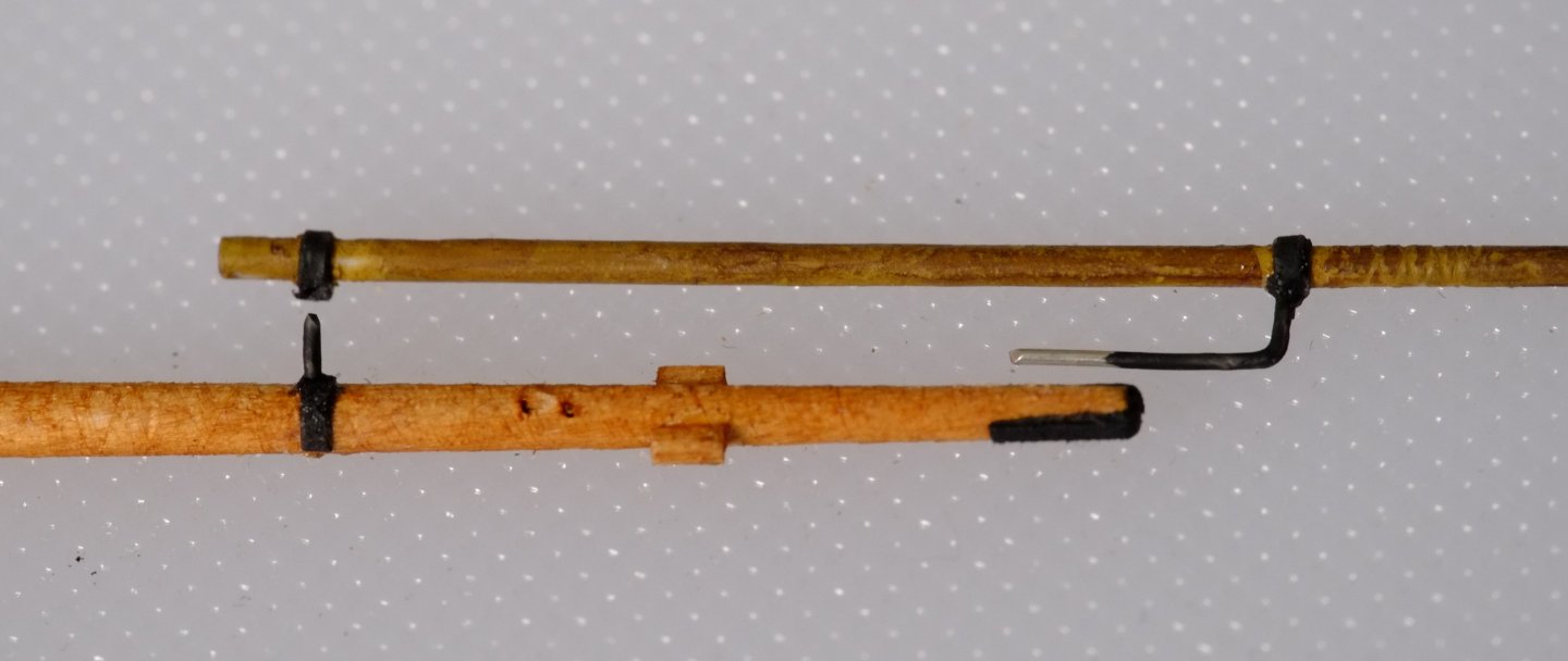
Cross-jack yard and square sail yard These are now pre-rigged as much as possible before attaching them to the fore mast. There are only a few lines, including four on the square sail yard for raising it, but a lot of blocks. The first photo shows the middle of the cross-jack yard. The yard sling is above it and has a lanyard tied on already. The eye is from the insulation on house wiring cable. Seahorse blocks hang below the yard together with horses. The next picture was taken a bit later and has the first stages of the truss tackle: small eyes on pendants pointing aft and long tails pointing up. When the yard has been slung the tails will go around the mast, through their opposite eyes and then up to a tackle that hangs below the trestle trees. Lever shows a lot of variations on truss tackles. Here is the port yard arm with the stuns'l boom retracted and lashed to the yard at its inboard end. There are stories of people who forgot to lash the boom and only noticed when the ship heeled over and the boom slid out and fell in the water... The little paper pockets hold coils of thread of different diameters, colours and lengths. I mostly use Gutermann thread (there is an Amati 0.25mm there too) and the various shades of pale and dark make a welcome change from the black or white supplied with kits. The starboard yard arm has the boom extended. There are 2mm Seahorse blocks tied to the boom at the outboard tip (off the photo) and to the boom iron at the inboard end. Both blocks hang upwards because the pull from the sheet and tack will lift them. The block that is below the arm is for one of the four lines used to lift the square sail yard. My collection of plastic wallets is expanding with a piece of paper and a yard or mast in each one. Those labelled, paper pockets will save time later. Fore mast I have returned to the fore mast which already has its shrouds tied on. There are a lot of blocks to tie on at the mast head and the photo below shows a selection. Going from left to right on the picture we have Lanyard tied to an eye, for the main topmast fore stay Block for the main mast fore stay (Caldercraft 5mm single) Block for the gaff peak halyard (Seahorse 4mm double) Block for the gaff throat halyard (Seahorse 4mm double) Two small blocks below the trestle trees for the truss tackle (Seahorse 2mm double) Block for cross-jack yard lift, hanging from an eye below the mast head Line for topmast top rope tied to an eye below the mast head It is crowded here and I decided to have eyes on long or short arms to carry the three larger blocks between trees and mast head. An alternative would be to give the higher block a longer pendant. The cross-jack sling and fore stays have yet to be coaxed into place, that comes later. My next task is to attach blocks and lines to the fore topmast. It is a couple of years since I planned the rigging and I try to trust my earlier decisions, but, the references come out again and I spend hours checking what should still be correct. This is the summary plan for the fore topmast. It's even more crowded. George


-
Happy New Year to all! I tied on halyards to the topgallant yard and the stuns'l yard previously and have now added a downhauler line to the stuns'l. Both of these yards are now stowed; I place them on a piece of paper and slide it into a clear plastic folder, the sort that opens on two edges. The photo below is the stuns'l yard and I have labelled the lines to avoid confusion when it comes to assembly. I have pre-rigged the topsail yard now and it has a few blocks and bits on it and a lot of lines. The next photo shows an arm with A jewel block tied to one eye (Seahorse 2mm single block) A reefing tackle that begins with the line tied to the arm, fed through a hooked block then back up through a sheave in the yard A horse A yard lift A yard brace The picture at the middle of the yard is similar and even more crowded. We have A halyard rising upwards Two eyes on pendants for the yard truss. The shorter eye has a fine line tied to it, ready to become a lashing. I used fly tying thread. A block for the bunt line below the yard (Seahorse 2mm) Two tackles for clew lines. These use Seahorse blocks and HiS hooks The way I made the eyes is described in a separate thread and other members also present their alternative methods The really complicated part is the huge tangle of rigging lines. I made small paper pockets and dropped the coiled lines into them, then added a paper clip to stop the lines from sliding out. The pockets and the lines are all labelled. One line does not have a pocket and that is the lanyard to lash the truss eyes together. The pre-rigged topsail yard was placed in its own plastic pocket, ready for assembly. My current work is on the cross-jack and square sail yards. George

-
Simple, low cost, small thimbles
georgeband replied to georgeband's topic in Masting, rigging and sails
Thank you all for your alternative methods for making eyes. They show inventiveness in materials and methods and all rely on the skill of the model maker. What we do not have is a commercial source of parts to use when we are faced with a rigging plan that demands a large number of very small eyes. There might be a solution that uses 3D printed parts or laser cut, laminated paper/card. My thoughts for a 3D solution drift towards a long tube that consists of a stack of eyes, all with suitable internal diameters and flaring at the ends, and clear grooves or partially cut slots to separate them off the tube. A laminated paper solution is probably quite conventional and similar to those for blocks. Are any of our commercial cousins thinking about this problem? This thread suggests that there is a market for tiny eyes. Best wishes for the New Year, George -
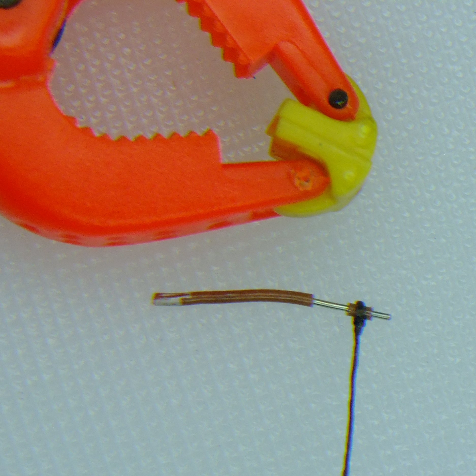
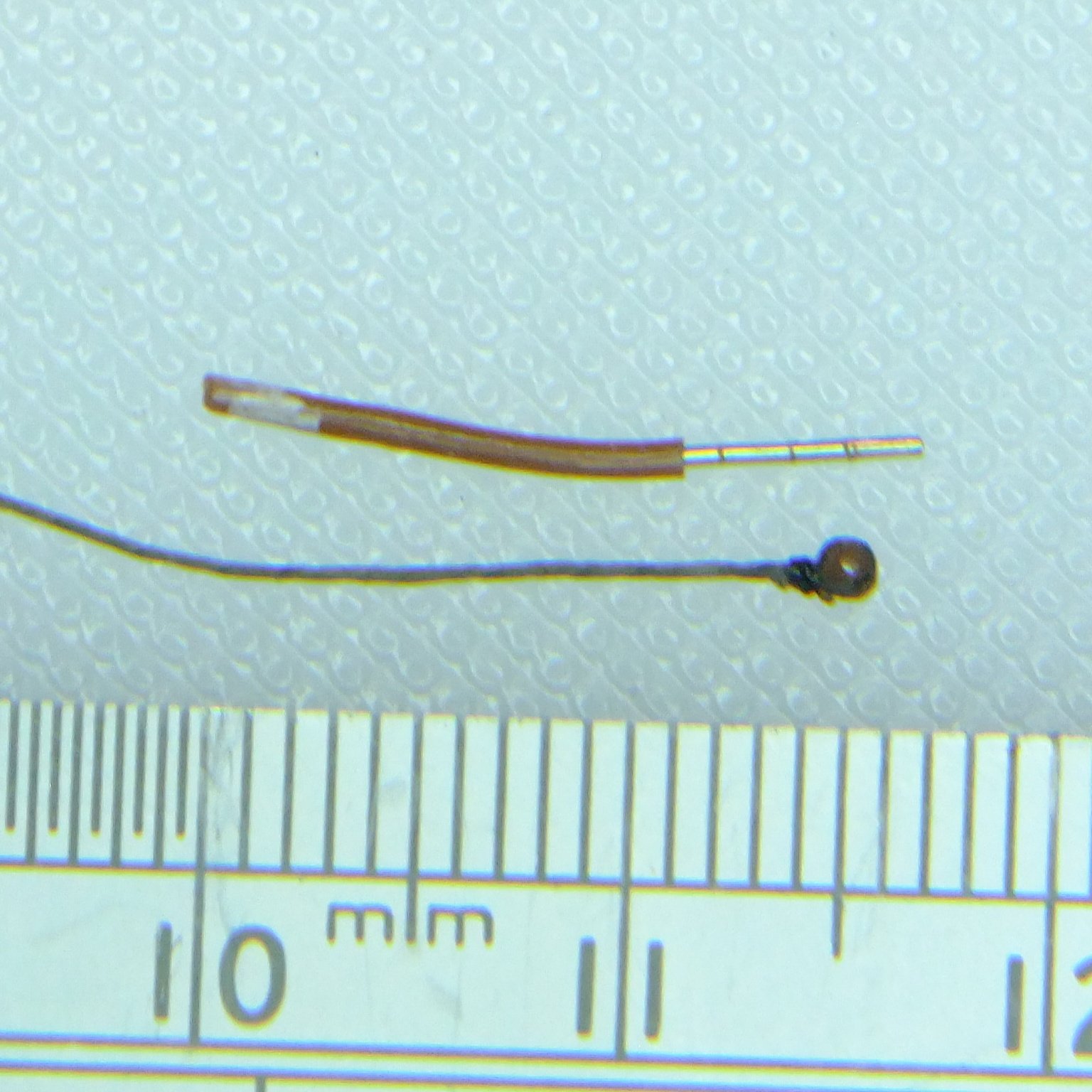
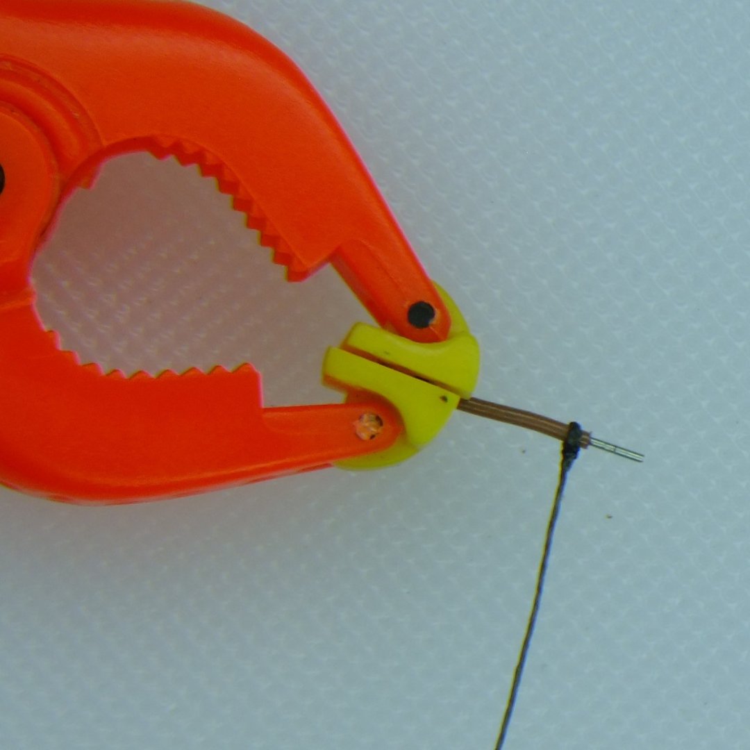
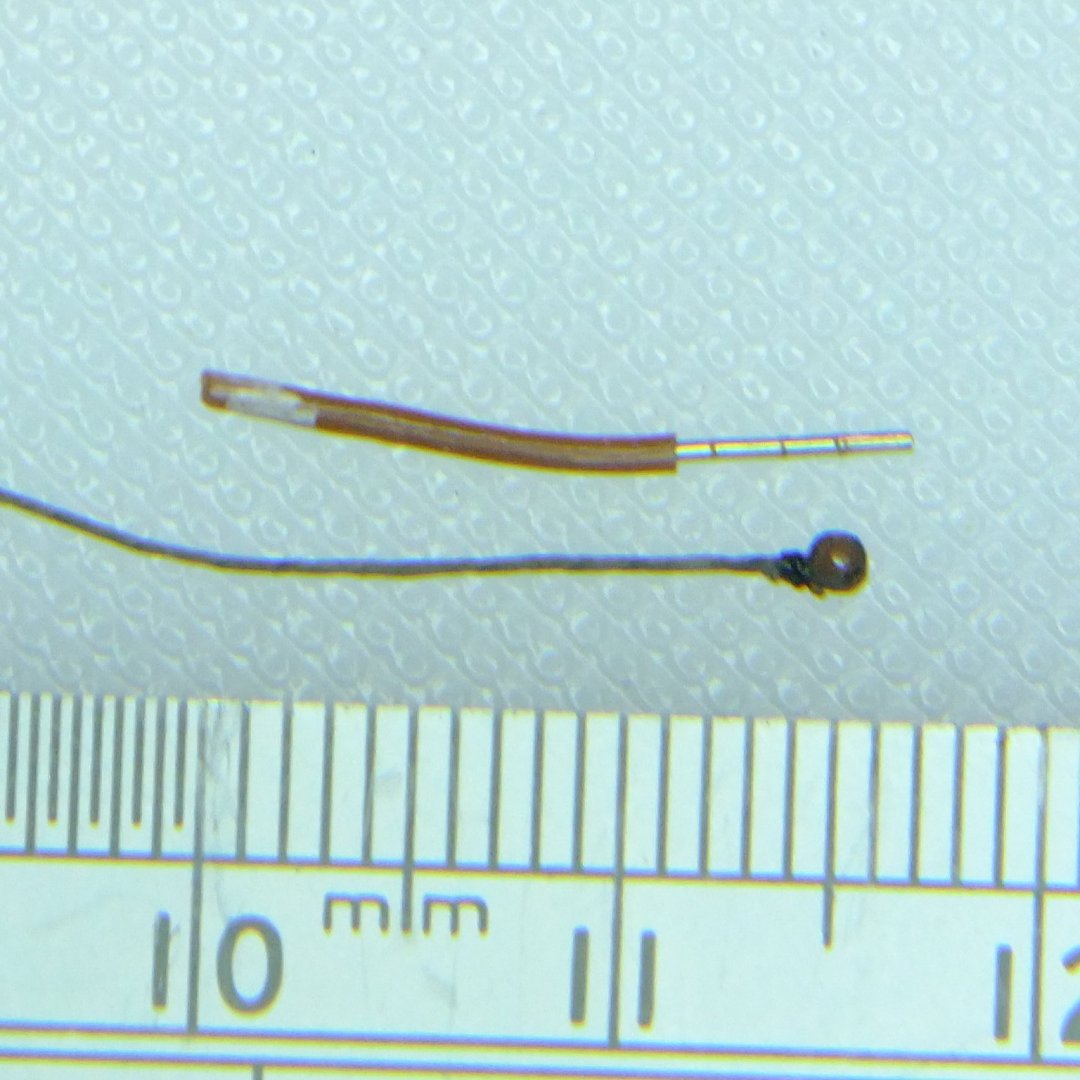
There are several forum sites that discuss the use of metal tube to make thimbles. They look good but are difficult to replicate for small sizes, for example to have a hole that is half a millimetre diameter. There is also the difficulty of aligning a thread or rope to go around a thimble and not slip off before the glue grabs it. I suffered this when I used plastic beads for thimbles... The approach I describe here uses the insulation layer on a wire as the thimble. I used reclaimed telephone wire that is 0.8mm diameter over the insulation and 0.4mm diameter for the single strand of copper wire. Take a short length of wire of a suitable colour (I chose brown) and glue the thread around it so that it forms a single loop. (I used Gütermann linen thread, colour 4010, which is 0.3mm diameter and can pass for a served and leathered line. Superglue darkens this thread.) Because there is a length of wire you don't have to be precise about where to place the loop or worry about it falling off. I used superglue and applied it with a pin that was barely wetted - if you can see a drop then it will drown the thread and refuse to harden, and instead wait for you to touch it with a finger. I then used dark brown, fly tying thread to seize the joint with a sequence of half hitches. Superglue does not stick well to the polythene insulation so the seizing performs its proper function and secures the join. The seizing also closes up the loop and so there is no visible gap between the thread and the thimble. Cut through the insulation and slide the thimble and line off the wire. The insulation layer can now be trimmed so it is flush with the rope ring around it. A fresh, sharp scalpel blade is vital for the trimming because a blunted blade will leave plastic hairs that are near impossible to remove. I have not yet needed to make larger thimbles which would use thicker wire. The useful colour for power wiring in the UK is brown (and black if you have hoarded some old or reclaimed cable) and the internal diameters are 1mm or more. George

-
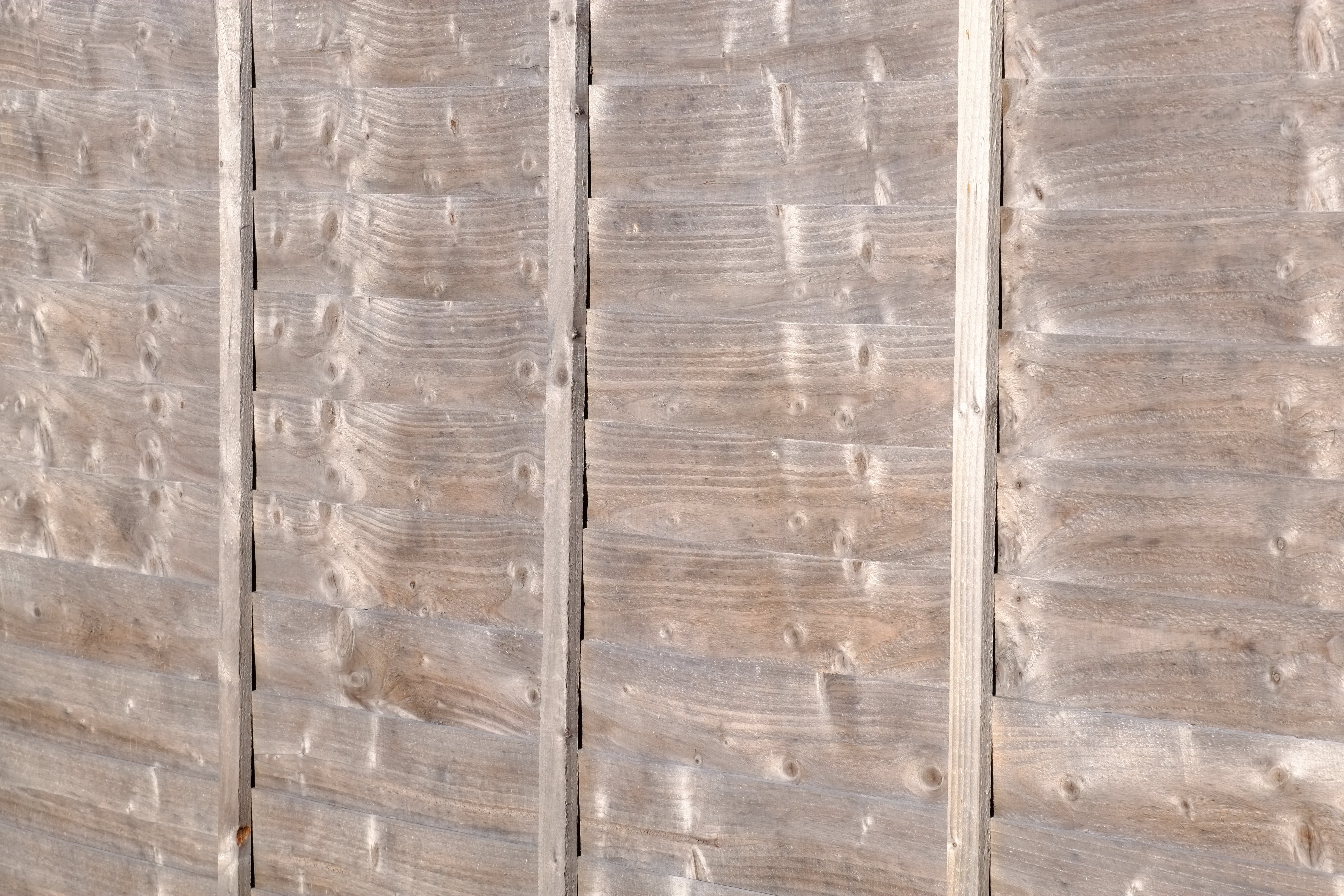
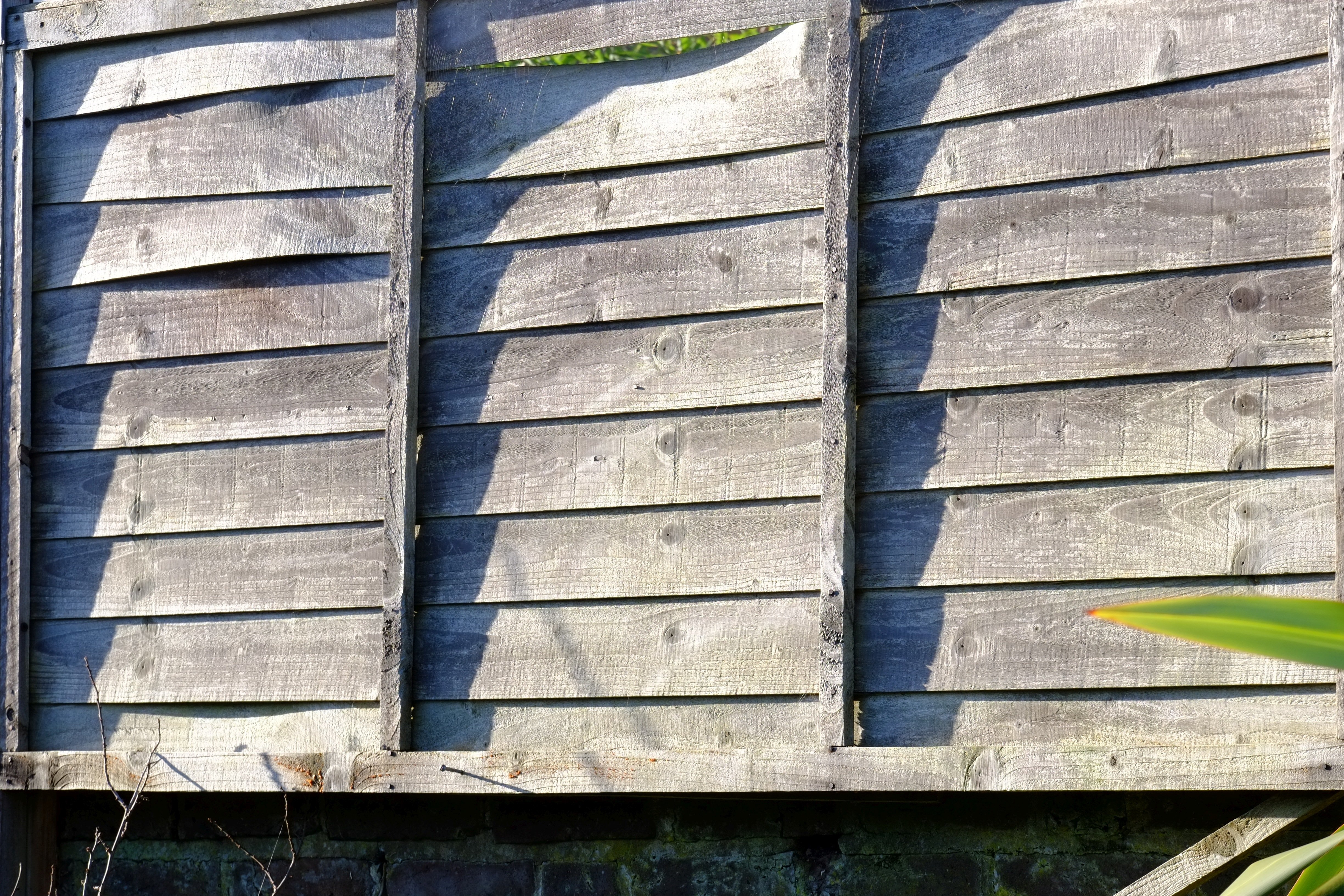
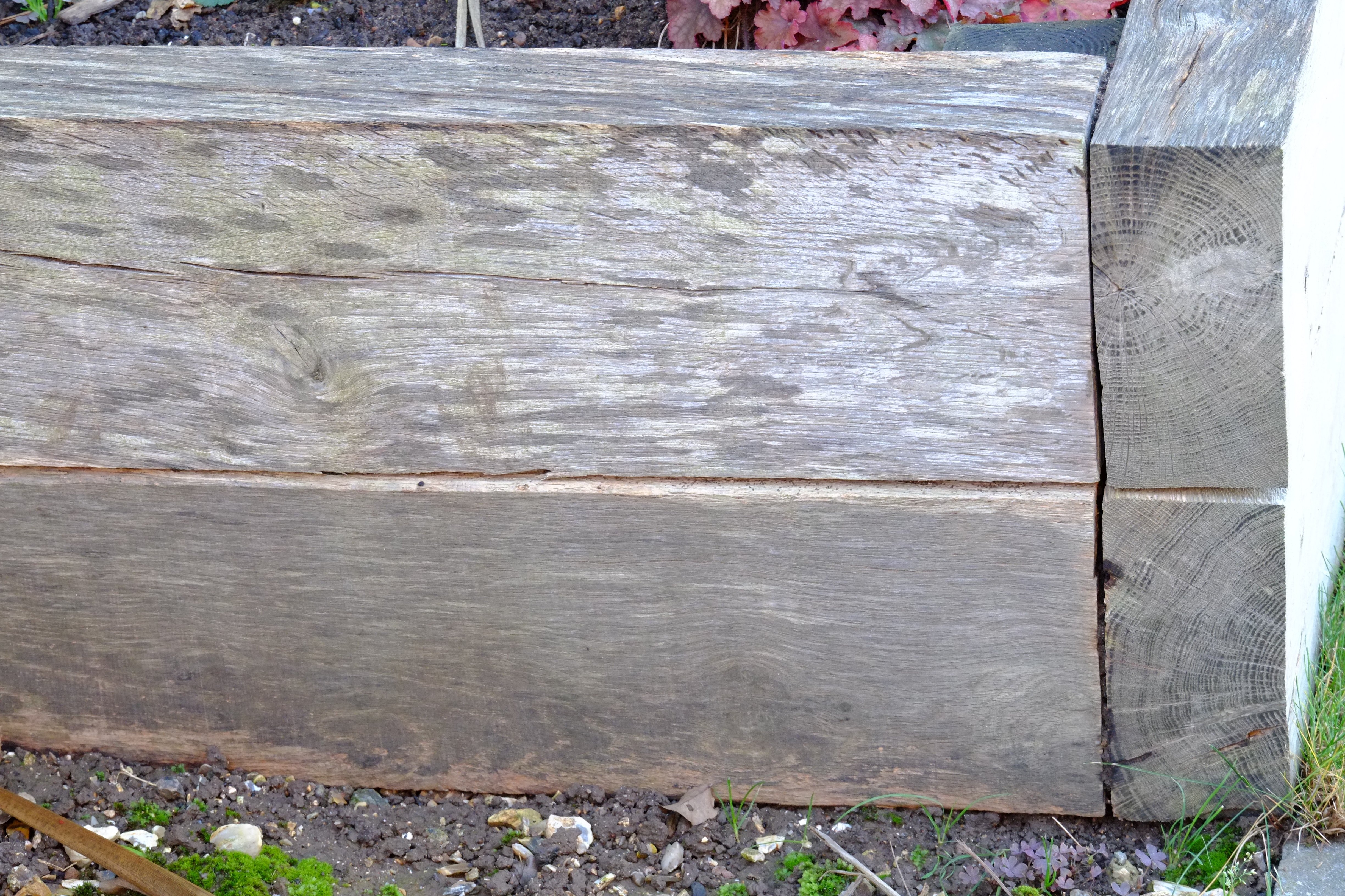
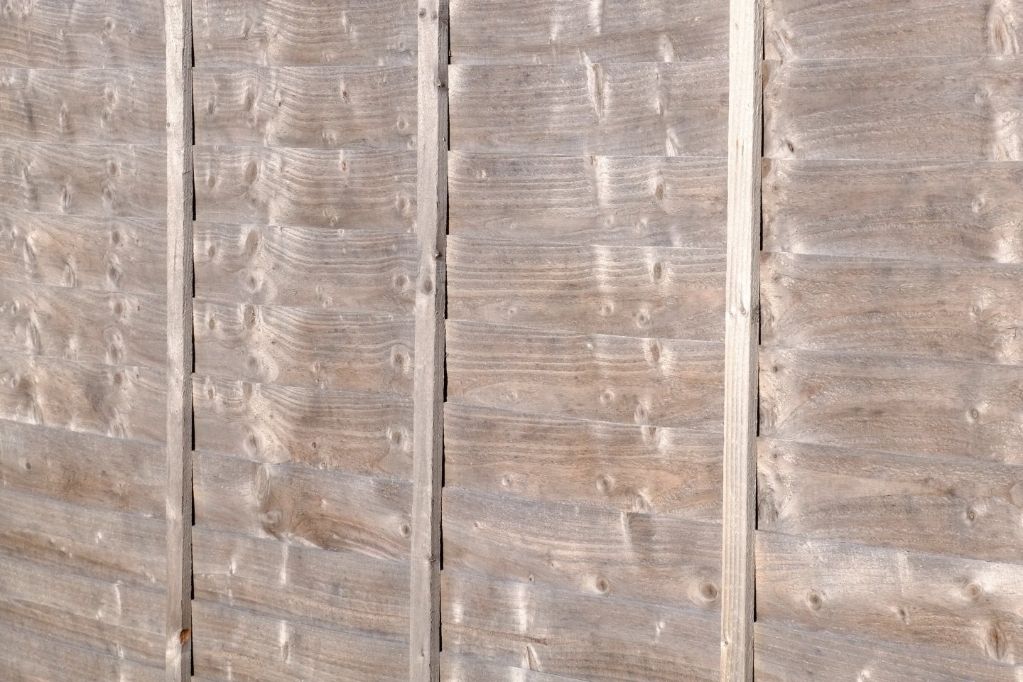
Tony, Thank you for your question which I think splits into three parts: what colour should the blocks be, how can we achieve this, and (less important) what have I done? 1. What colour for blocks? My guess based on hazy memories of what I have read is that the blocks were natural, weathered wood, probably elm. They might have been varnished at some point but I doubt if sailors would climb up with sandpaper, a bucket and brush to renew the varnish. The photos below are from my garden in the winter sunshine and show two fence panels and some oak sleepers. The fences are nondescript soft woods. The oak goes dark brown when it is wet, and dry it has a lot of variation. My impression of weathered wood from looking around is mostly grey with a hint of beige/pink/brown to it and this is what I try to achieve. 2. How to colour the blocks Larger blocks, 4mm to 5mm for example, can hang from a bent wire and be sprayed with a colour of your choosing. If like me you prefer a hairy stick to an airbrush then the technique is similar though the blocks need to rest on something like kitchen wipe paper so they don't flap about. It can be done and then the wires are hooked 'somewhere' while the paint dries. There is a separate risk that the holes get blocked with paint. For smaller blocks such as 2mm the technique is still achievable but more fiddly. 3. What did I do? I took the easy option for 2mm blocks and left them as raw resin. The colour is similar to my fence panels, and the wooden blocks next to them (see my previous post) look toy-like to me in comparison. I will consider painting or staining the larger blocks when I get to them, both wood and 3D printed. I launched a long term experiment in May 2024 when I left resin bases from the Seahorse 3D printed blocks on my south facing window ledge (indoors). Sunny Worthing gets a lot of sun by UK standards and I have not found any effect on colour or material properties after two bright summers. I don't expect the unpainted resin blocks to fare worse than a painted finish or wood. Suggestions or comments? I assume that other model makers have different priorities and for them a display piece with fine woodwork in the blocks aspires to a different ideal. What are you trying to recreate? George


-
Square sail yards and booms cont. I started at the top and am working my way down the fore mast, attaching all the bits and ropes to the yards. The top gallant is easy and just has a halyard (Gutermann polyester, 724 colour) tied on with a Fisherman's bend. I tied a similar line to one stuns'l yard with a stuns'l halyard bend that I found in Luce Seamanship, plate 15, figure 90. I could have used reef knots because the proper bends are only visible under high magnification but it feels good to know that they are there. The topsail yard is still quite bare and I have attached a jewel block to each arm, using a Seahorse 2mm single block and a copper wire eye from Caldercraft. Gluing the rope around the block was a good test for shaky hands. The port side block will just dangle from the eye and the starboard will route the stuns'l halyard. The reef block uses a HiS 2mm single block and a HiS etched brass hook and strap. The line is again Gutermann 724 and it passes through a sheave hole in the yard. I returned to the stuns'ls and made the fittings for the booms on the cross-jack yard. Starboard side has the boom extended and port side is retracted. I deviated from actual practice and the booms are fixed in place with wire pins and do not slide in the iron rings apart from one - the outer boom iron to port. The booms have not been fitted yet and will be glued on after more ropes and blocks. The inner ends of the booms will be lashed in place. Copper wire and black paper were the main construction materials and precision drilling the technique. It's not fast but it is progress. George


-
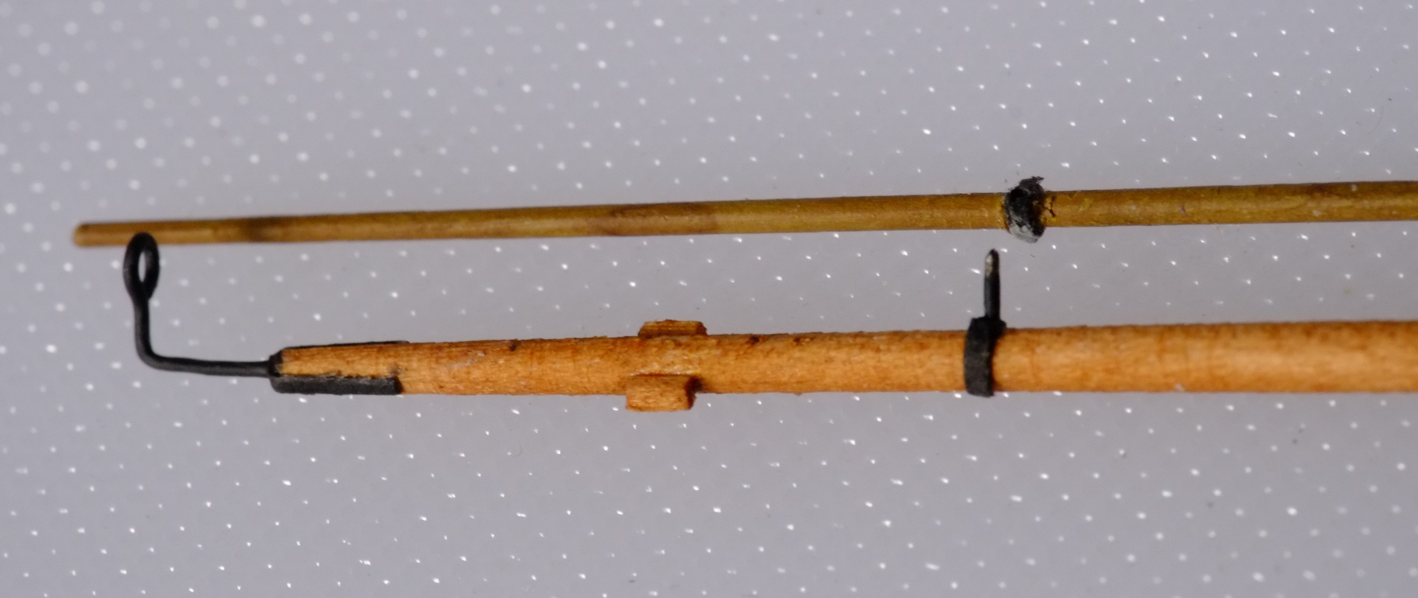
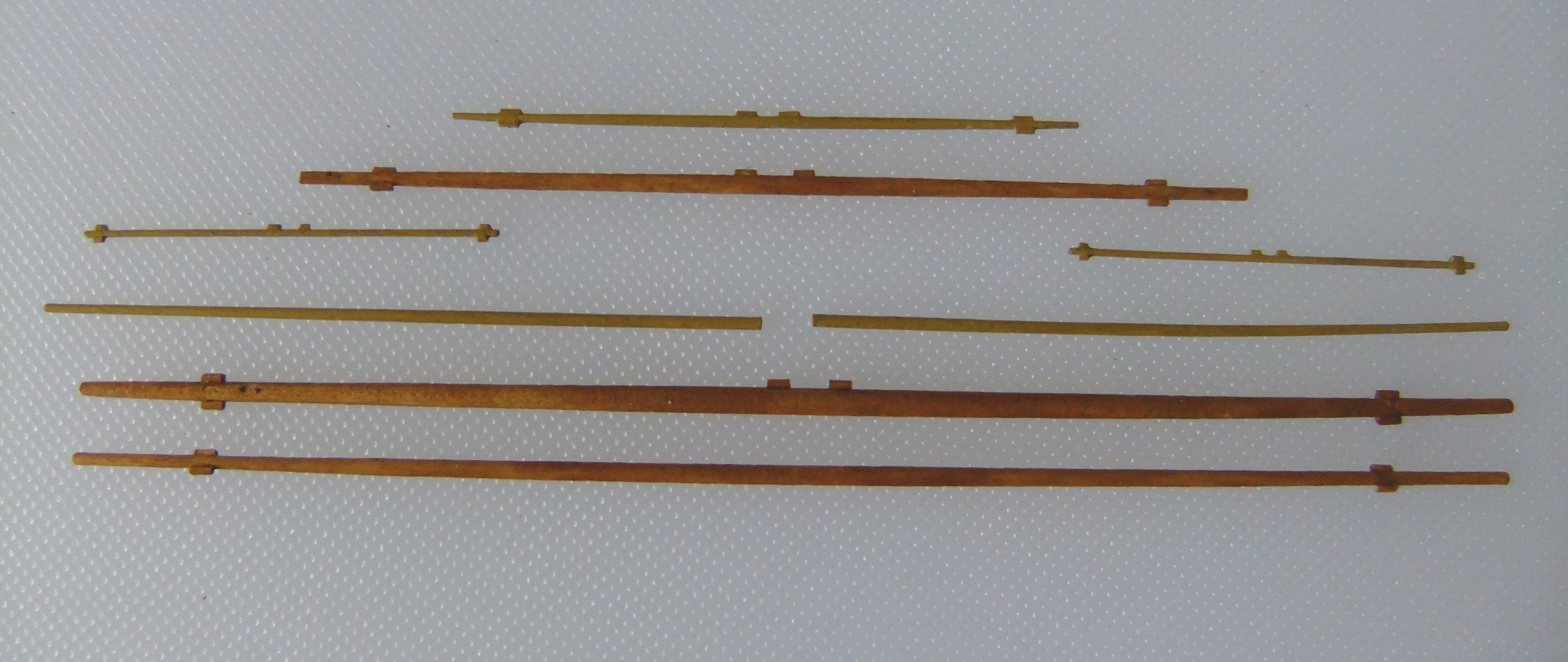
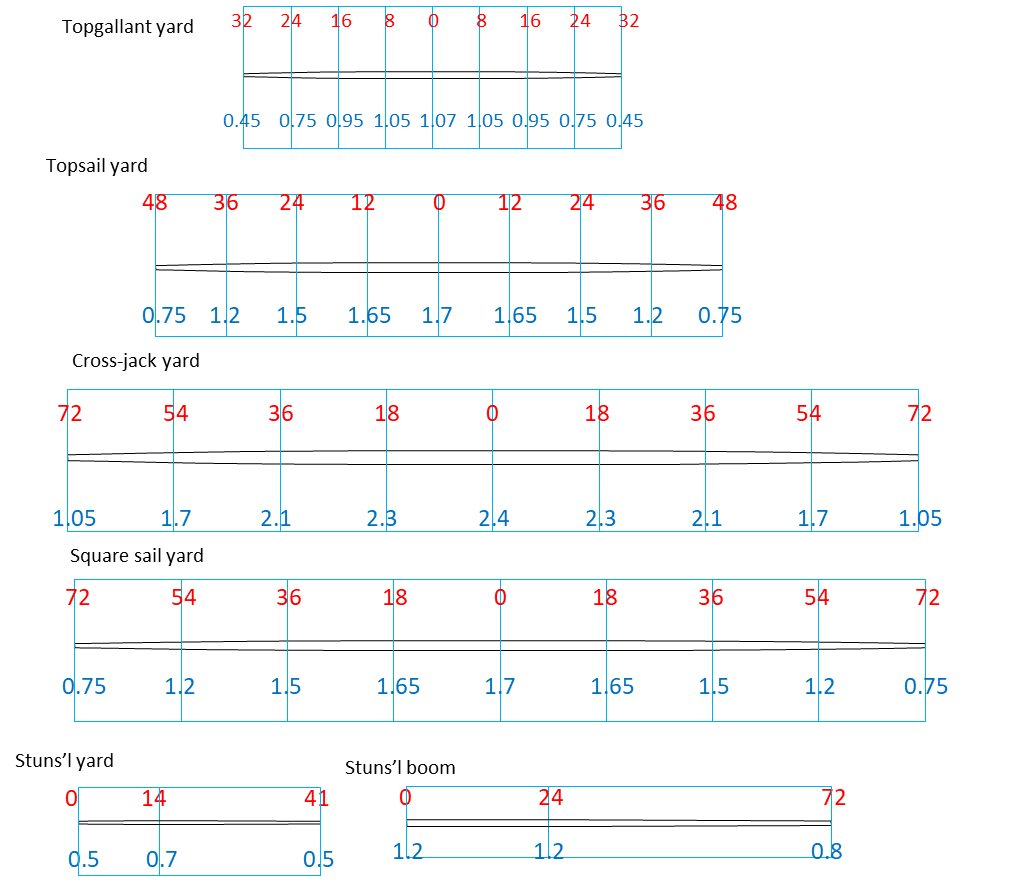
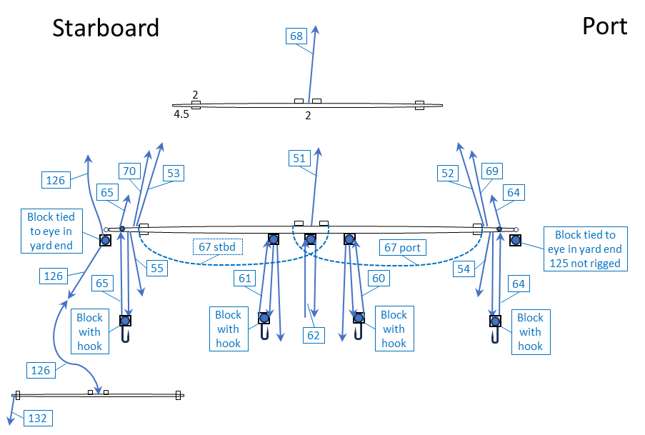
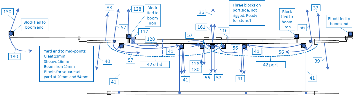
Square sail yards and booms I finally decided on the sizes of the square sail yards (topgallant, topsail, cross-jack, square sail) and the studding sail yard which hangs from the topsail yard and the stuns'l boom that projects from the cross-jack. The drawings below show the distances along the spars in red and the diameters in blue. The diameters at the quarters follow the standard proportions (30/31, 7/8, 7/10, 3/7) and are rounded to the nearest 0.05mm. The larger yards I made from wood, turning it with an electric drill while gripping it with sandpaper. Dowel stock 3mm diameter was the basis for the cross-jack yard. I found on Ebay a pack of 100 dowels that were 2mm diameter and 200mm long and spent a few pounds on them. They are from some close grained wood and were perfect for the topsail and square sail yards. The ends of the topsail yard should be 0.75mm diameter but I stopped at 1.0mm to allow enough material to drill holes into the ends of the yards. The smaller yards started as polystyrene rods and I reduced the diameters by hand sanding. The stuns'l yards stayed a constant diameter because the reduction would not be visible. I glued cleats on to the yards following Steel's guidance, and drilled holes for eyes and sheaves. The wood spars received a coat of 'European larch' wood dye and the plastic spars were painted khaki with enamel paint and then a wash of burnt umber. (The photo is at the khaki stage.) The stuns'l yards have their halyards tied on at the middle because that works with the other yards to give a reasonable overlap between the studding sail and the topsail on my model. The books typically place the halyard '1/3 of the way along the yard' and accept that it was not a precise rule, so I have a justification for my decision. Today I have made a start on the studding sail irons and will continue with other bits on the yards. My intention is to have the spars well clothed with ropes and sails before I fit them to the mast. The preparation for this stage was time consuming and I continue to make small adjustments to rigging plans, flipping between Powerpoint and Excel pages and the books that inspired me. I am glad that my Excel files have columns that show which books and pages I referred to for each rope. The numbers in blue boxes below are the numbers I assigned to the ropes; they go up to 161 at present. The first picture is for the topgallant and topsail. Below that is one for the cross-jack and square sail yards. Photos later. George

-
Trevor and Phil, Thank you for marking my homework, finding more information, and guiding the interpretation of the names for yards. It is a messy subject in much the same way as 'hounds' on masts. Different contemporary authors use different terms and are not always self consistent. I propose to use cross-jack yard for the lowest yard on the foremast of a schooner because people know what a cross-jack is and does. Its principal function is to guide the topsail sheets. It is not routinely raised or lowered. I propose to use square sail yard for the yard that has a square sail (course) bent to it. This yard might be the same length as the cross-jack yard or it might be much shorter or it might even be absent. The square sail is raised by hoisting it and the square sail yard up to the cross-jack yard. I hope this helps for other model builders. George
-
Cross-jack and Spread-yards I fell down this rabbit hole after Trevor's and Phil's comments and have tried to find the histories of these words. Marquardt appears to draw fine distinctions between them but is not supported by current dictionaries. The Oxford English Dictionary which defines over 600,000 words does not show spread yard and neither does the Oxford Companion to Ships and the Sea. I then tried contemporary sources, first looking at Falconer's dictionary and JJ Moore's dictionary. They had identical definitions for cross-jack yard and no entry for spread yard. Four books on masting (Steel, Kipping, Cock and Fincham) all mention cross-jack yards and only Steel mentions spread yards. The interesting aspect of Steel is that the two entries for spread yards are in tables along side cross-jack yards, so there is some difference between them. Cross-jack yards are more common in his text and also appear in two drawings - plate 5 and the square sail by section 124. The entries in Fincham (1829 edition) are for three possible candidates: square sail yard, lower yard, cross-jack yard. Square sail yard appears in combination with lower yard or with cross-jack yard. Cross-jack yard appears on its own in some tables. The entries in Fincham (1843 edition) are for three possible candidates: square sail yard, lower yard, cross-jack yard. Square sail yard appears in combination with lower yard. Cross-jack yard appears on its own in sections on brigs and ships. All three are in one table, page 163. Kipping and Cock only refer to cross-jack yards, unless I missed something. My interpretation? I think that for Fincham cross-jack yard refers to a yard without a sail on the mizzen mast (or on the main mast of a brig). Its role is to carry the sheets from the topsail above it. I think that the lower yard performs the same function on the fore mast of a schooner and the square sail yard has the sail bent to it. The square sail yard with its sail is hoisted up to the lower yard, which in Fincham has a thicker diameter than the square sail yard and the same length. I also think that Steel's spread yards and cross-jack yards refer to the same two yards as Fincham (lower and square sail) but I do not know which is which. Cross-jack yard in Fincham I think applies to mizen or aft-most masts. The short square sail yards that Trevor and Marquardt describe are variations on this theme with a change of name. There is also absence of evidence in contemporary drawings to support Fincham's definitions. I might be trapped in this rabbit hole for a while longer. Is this reasonable? George
-
Trevor, Thanks for your comments. Marquardt says a lot about crossjack and spread yards, pages 182-3, and according to his definitions a spread yard is permanently in position while a crossjack can be raised and lowered. He also talks about club yards as variations at the head of the square sail. They can be full width which is what I tried to describe, or just over the middle of the sail, or missing entirely when halyards are tied to the head rope in several places. As with most things schooner, anything appears to be possible and there are few rules or guidelines to follow. It might have been better for me to call the permanent yard a spread yard and describe the one to which the sail is bent as a club yard. That name probably has connotations of being temporary. George
-
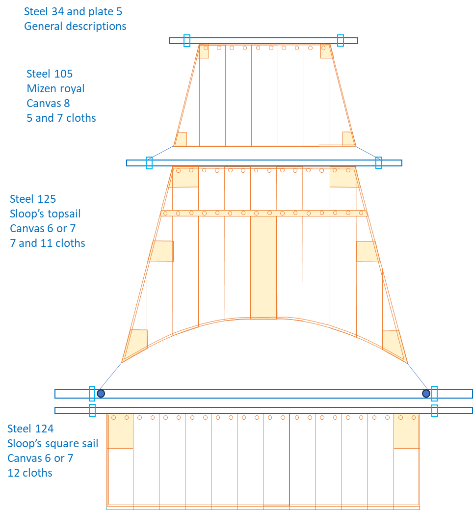
Fore mast square sails and yards It has taken me a week to understand Steel Rigging and Seamanship and Lever Young Officers Sheet Anchor well enough to make some progress with the design of the square sails and their yards on the fore mast of Whiting. My other approach, scaling down the sail plan of HMS Adonis, drawing ZAZ6196 from the NMM, was a first step and a check on the results. Steel provides information about how the yards project beyond the sides of the sails. Section 34 is a general introduction but it is not always obvious what his words mean and I compared them with the drawings in Plate 5 to prompt a fresh interpretation. Later sections (15, 125, 124) describe particular sails and require some creativity to adapt them from a 36-gun ship to a 4-gun schooner. Lever was also useful at this stage. I then had an iterative process of guessing a sail pattern, for example choosing the number of cloths at the head and at the foot, calculating the total length of the yard, and comparing that with the measurements from Adonis. When I was close to a reasonable answer I drew the sails with basic representations of yards to see if they looked right and finally arrived at the sail plan below. The yards and the cleats at the yard arms are shown by simple rectangles for now. Top gallant sail This sail was set flying so there is little rigging to worry about. I based mine on the mizen royal, number 15 in Steel, which is about the right size and function. 'Canvas 8' denotes the thinnest, lightest material. '5 and 7 cloths' refers to the number of canvas cloths at the head and foot respectively: it was usually a whole number. The topgallant yard comes out at 65mm long which is 5mm longer than a scaled down Adonis. Topsail This has a reef band and more strengthening patches. Steel has a relevant description and drawing in section 125 for a sloop's topsail which I adapted. 'Canvas 6 or 7' is not quite the lightest and there are 7 cloths at the head and 11 at the foot. The topsail yard works out at 95mm long which is 11mm longer than what I estimated from Adonis. Spreadyard and square sail (course) Steel has a description for a sloop's square sail in section 124. On my model this sail is folded and stored below deck so I have only drawn the top part to check that it looks in proportion. The yard is 144mm long which is only 2mm more than my Adonis estimate so I am happy with that. The topsail yard in Steel, plate 5, which is the inspiration for my spreadyard has two sheaves in each arm; the outer one is for reefing tackle and the inner for the topsail sheet and I have included the inner sheaves on my drawing. A major difference from a 'conventional' spreadyard is described by Marquardt in Global Schooner where he suggests that an occasionally used square sail (course) could be hoisted up on a crossjack yard. I cannot think of where to stow this yard on Whiting where there is no spare space and guess that it hangs from the permanent spreadyard to keep it out of the way. When the square sail is needed my guess is that the temporary crossjack yard is lowered, the sail is bent to it and then hoisted up. Does anyone have evidence for this, or an alternative? John Roach in his logbook mentions the fore square sail once so this problem had to be dealt with on the real vessel. Studding sails The yards for the studding sails hang from the topsail yard and I assume that they are kept below when not needed, though their halyards probably route through blocks at the yard arms and remain in place. The booms for the topsail studding sails will sit on the permanent spreadyard and demand a few extra blocks. Learning about them is for another day. George
-
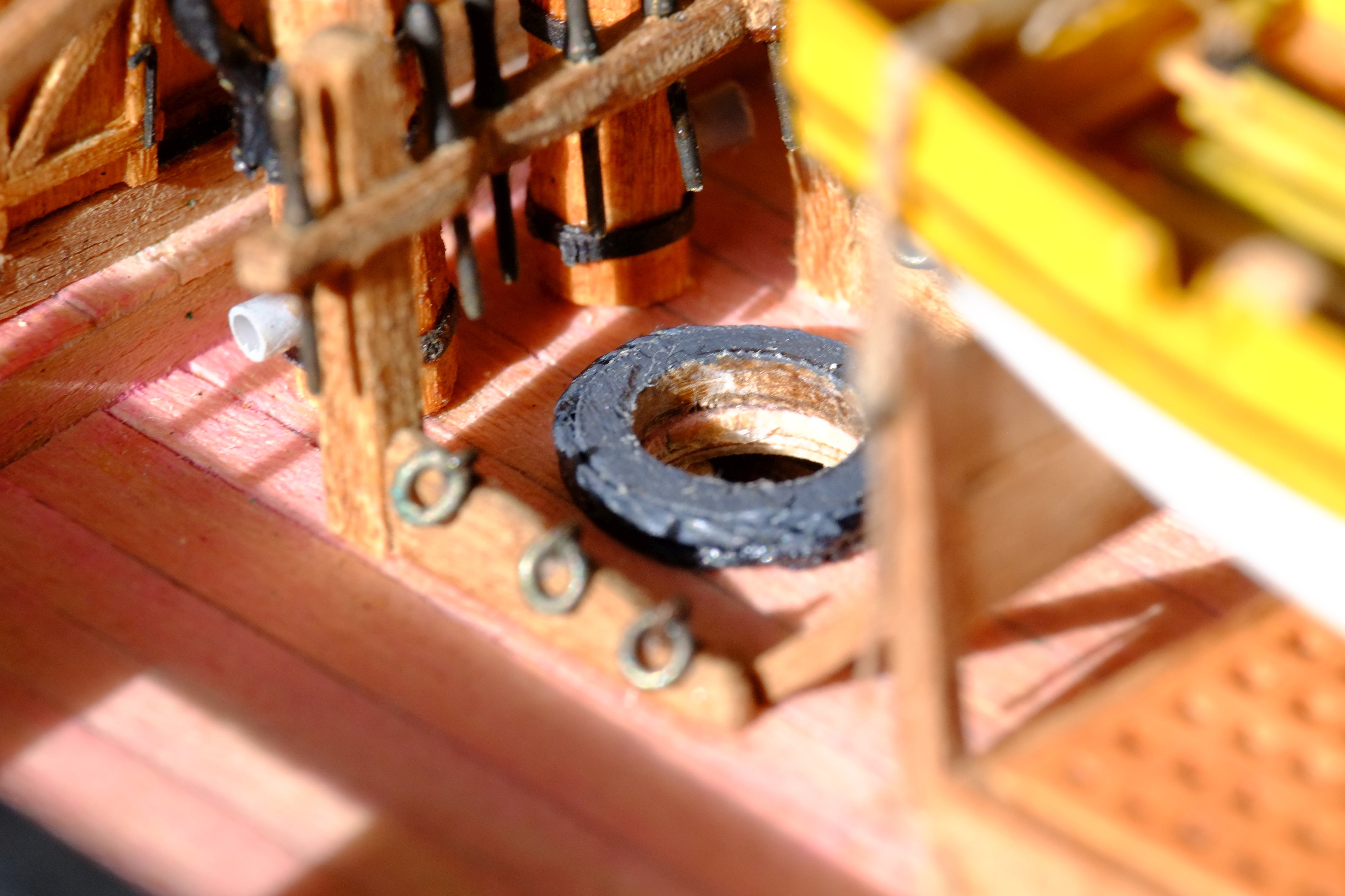
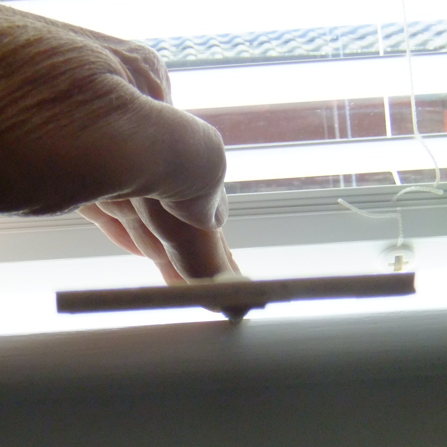
The hull is complete and both masts have now been built and the shrouds and pendants tied on. Not bad for 900 hours spread over ten years. The main mast is very similar in construction to the fore mast and I shall focus on the differences here. Creating square sections I improvised a method for aligning the faces of a square section with a slot in the heel of the round mast. The slot will sit on the ply spine inside the model and for now I glued in an offcut of ply with PVA; it holds well enough and the joint can be worked open and the ply removed at the end of the build. The first photo shows how I press a recently sanded square face down onto a window ledge and check by eye that the ply offcut is parallel to the ledge. Repeat the procedure for the opposite face. The two remaining faces, fore and aft on the mast, have to be perpendicular to the first two faces and I used a shelf above my desk that has a picture frame on it. Anything with a right angle will do. Just press the new face down. Partner ring The deck is very crowded around the main mast and the partner ring is in two parts. One is glued to the deck and the other, just some thick grey thread, is wrapped and glued around the mast. When the mast is slid into position the two parts line up and look like a credible attempt at waterproofing a hole in the deck. Cleats and shelf for boom The belaying plan that I worked out needs five cleats at front and sides of the main mast. I guessed a height that the crew could easily reach but did not clash with all the other belaying points. The cleats are Caldercraft pieces. The shelf that supports the boom is a ply ring with eight triangular supports below it. At first I was going to position it parallel to the waterline and boom but realised that this would twist the boom when it was out to one side or the other. Having the shelf perpendicular to the mast prevents this problem but the underside of the boom jaws will have to be chamfered. I coppered all the way around the mast above the shelf. One piece of hull copper plate almost reaches round, leaving a gap slightly less than 1mm wide. I filled the gap with an offcut from plating the hull that shows closely spaced nails. I imagine that a coppersmith would have used the same sheets of copper that were readily available. Main topmast heel On the fore topmast I built up layers of paper on a 4mm dowel and then carved down to a square section with 4mm faces. On the main topmast I carved a square section with 2mm faces on a 3mm dowel and then glued pieces of 3x1mm walnut to the faces. It is more robust than the paper corners on the foremast. Trees and shrouds The trestle trees are identical on the two masts but the cross trees on the main mast do not extend beyond them because there are no shrouds to support the topmast. There are only two shrouds to each side of the main mast. The first pair to go over, starboard, are for the pendant (aft-most) and one shroud forward of it. The second pair is the same to port. I made these from linen that I painted ochre to simulate serving over their whole lengths. The photo shows these two pairs fitted over the grommet and bolsters. The final pair of shrouds, one each to port and starboard and foremost on the mast, are a swifter pair made from Ropes of Scale 0.6mm rope. The centre portion (11cm) was painted to simulate serving. Tying on the seizings was tricky for this pair but making an eye splice at this scale is not an option for me. The last two photos show linen and Ropes of Scale ropes that have been painted with about 4 coats of ochre, acrylic paint to simulate serving. I would argue that 'real' serving with fine thread is an example of artisan craftsmanship which is not really visible at this scale and put it alongside treenails in decks, nails in copper plates and stitching on sails. Debate it if you have strong views one way or the other. I have made my choices and respect yours, whichever way they go. Currently I am looking at the sail plan and preparing drawings for yards. There is a lot of informed judgement here (or guesswork as it is also known) and the woodwork and knot tying will come after that. George


-
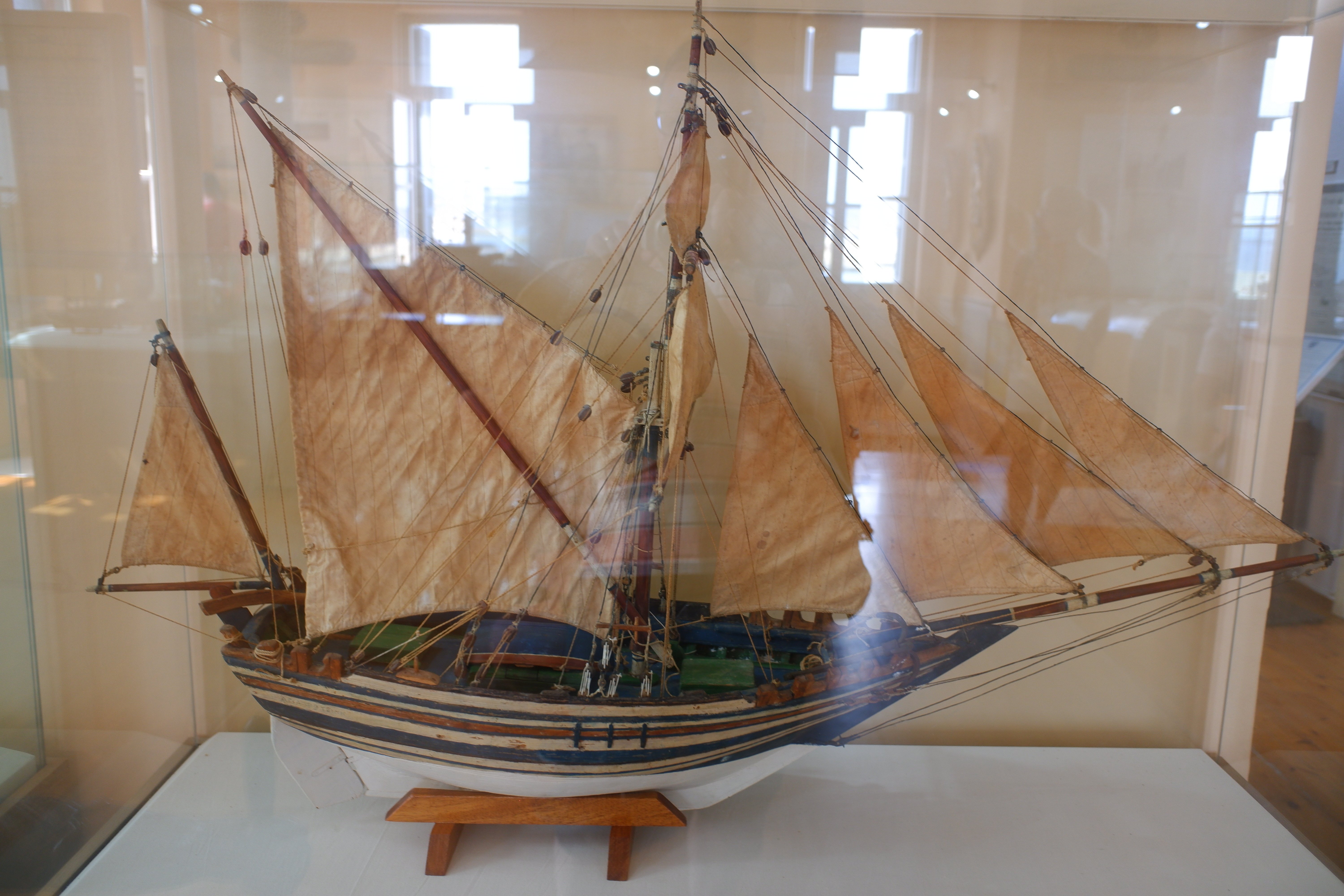
It's all so long ago... We had a holiday, then the summer was spent on DIY and grandchildren, then a late holiday, and now finally I have resumed building. The current task is the main mast, including its topmast section, which is very similar in construction to the fore mast. I will post some pictures later. (If anyone calls in at Chania in Crete it has a maritime museum that is packed full of models. Some are sailing ships and some depict the Greek navy now and in the 20th century. The sailing ships include rigs that I have not seen or heard of before, including the scaphi in this photo.) George

-
I'm a bit late to this thread and return us back to clamps for tapering planks. I wanted to have top-and-butt planks on the sides of my 1/64 model and it is critical to make the tapered edges straight, otherwise gaps will appear on the sides of the vessel. The heights at the ends of the tapered sections also have to be identical. I filed the profile I wanted onto some brass angle section to make left and right hand templates. These are clamped to a flat piece of wood with the width of the gap between them adjusted to hold several planks: four or five worked well for me. I then used a craft knife to cut away the protruding wood, always cutting away from the peak and towards an end so that if the wood did split it was the waste that was affected. Side view of the jig Top view of the jig The photo below is a work in progress view that shows one row of top-and-butt planks fitted. The second row will have the planks the other way up and front-to-back inverted so the tapers match. Finally the finished article where it is difficult to see the joins between the planks. My reward for all the work with tapering is a feature that is nearly invisible unless you know what to look for (it's the bare wood between the copper and the yellow ochre). Perhaps I should have had a caulking line to emphasize the joins. George


-
Phil, Have you considered the effects of water on the plank you need to insert? One option is to wet the plank to soften it and then squeeze it into the gap. This might be tricksy because the plank will have widened. The other option is almost the opposite: dry your plank thoroughly so that it shrinks a little across the grain and it might be enough to make a difference. George
-
Chris, Thank you for a most useful and informative article about copying pictures from the web. Could I ask you to venture into an adjoining minefield, one where the original source document is on paper? We all have our favourite reference books and some of these are long out of print. Two examples that I can point to are Modelling the brig Irene by Petrejus (1970), and Young Sea Officer's Sheet Anchor by Darcy Lever (1819 for original 2nd edition, and also 20th century reprints). There are lots of others which generally fall into these two categories: relatively modern but out of print, or antique but available as facsimile copies. I can scan pictures from books that I have, or find them already scanned on the internet. I believe that copies of pictures for personal use are legal and allowed but I do not know the position for wider distribution such as posting on MSW. Can you advise please? George
-
I have had a look through Petrejus Irene to see what he says about Dutch build practices. Petrejus quotes several references but they are from around 1820 to 1840 so might not be correct for earlier practice. JC Rijk, Sheepsbouw, 1822. pp 132-134 HA van der Speck Obreen, 1843 JC Pilaar, Handleiding tot de kennis van het schip en deszelfs tuig, Delft, 1826 W van Houten, De Scheepvaart, Breda, 1833 I have had a quick look on Google but my knowledge of Dutch is minimal and I did not find any nice pictures... Perhaps someone else will fall down this rabbit hole of research. The information and its interpretation by Petrejus is centred on its relevance to Irene which was captured in 1811 and refitted. It might be relevant for De Braak. Overlap of plates on hull There is general agreement that the Dutch overlapped the plates on the hull in a conventional way. The trailing edge of one plate went over the leading edges of the plate astern. The upper edge of a plate overlaps the lower edge of the plates above it. Plates were fitted from the stern forwards and from the keel upwards. Overlap of plates on keel Petrejus has nothing specific about the order of plating the keel but he does write '32 ounce sheathing was used for the bows and for the parts between wind and water, 28 ounce sheathing for the rest of the bottom and 18 ounce for the lower side of the main keel, between it and the false keel'. Nail pattern on plates Petrejus shows a picture of a plate with nails in a square pattern (from van der Speck, 1843) but there are 5 rows and 14 columns for these nails. The square pattern could have been in use for a long time or it might be a more recent development. The proportions of the plate in Petrejus' picture are quite different from the standard RN plates. Could a copper smith simply use the pattern that someone else had shown him and there was no regulation about how to space the nails? How was the keel plated? My guess about this is that plates were laid lengthwise on the bottom of the keel, a single plate wide with the edges folded up over the sides by an inch or two unless the keel was wider in which case two plates would run in parallel. The photos placed above show copper coming from the keel-false keel join and extending enough up the side of the keel to give a tight row of nails. This row could be hammered in place after cut-down plates had been fitted to the sides of the keel. The plates on the side would have their top edge trimmed and bent to go over the lowest hull plates and were hammered down after the first hull plates were fitted. This sequence ties in with the bottom-to-top rule and the rule about lower plates overlapping upper plates. I have not tried to fit in the staples to this sequence and might return to it later if I feel brave. George
-
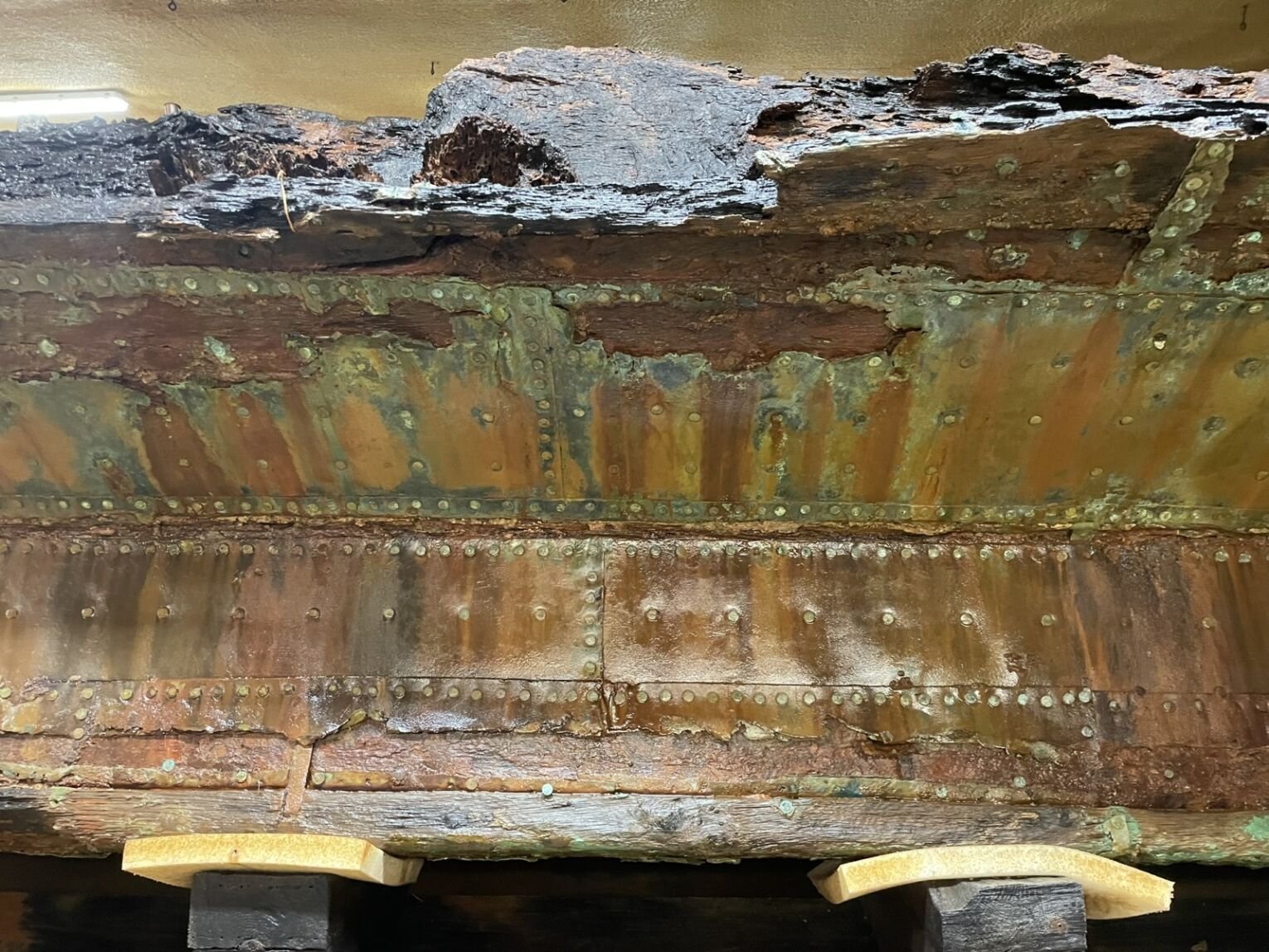
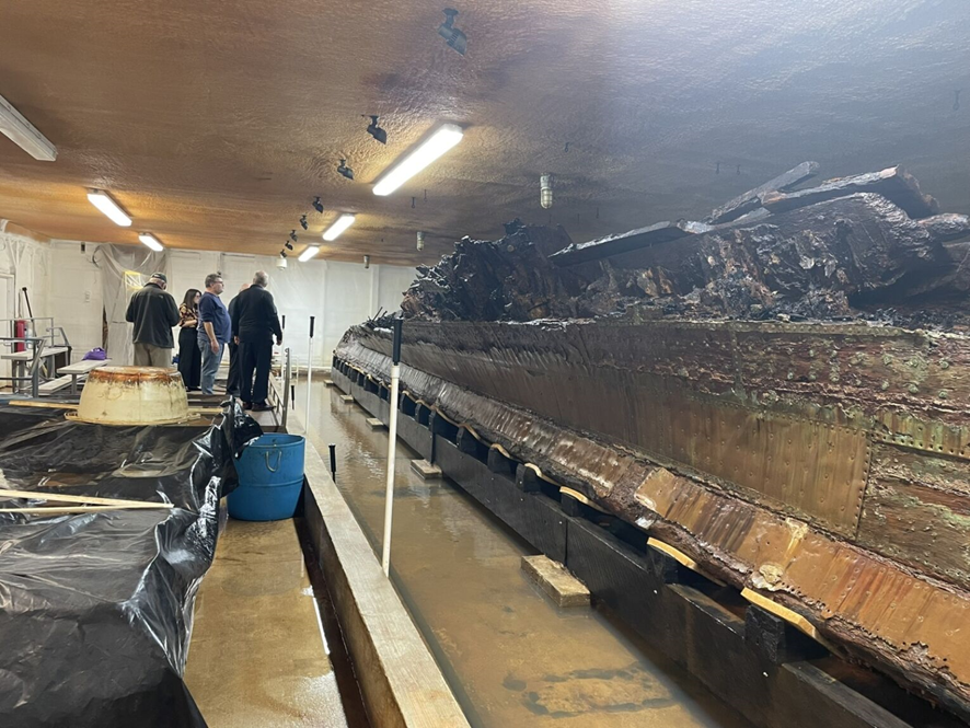
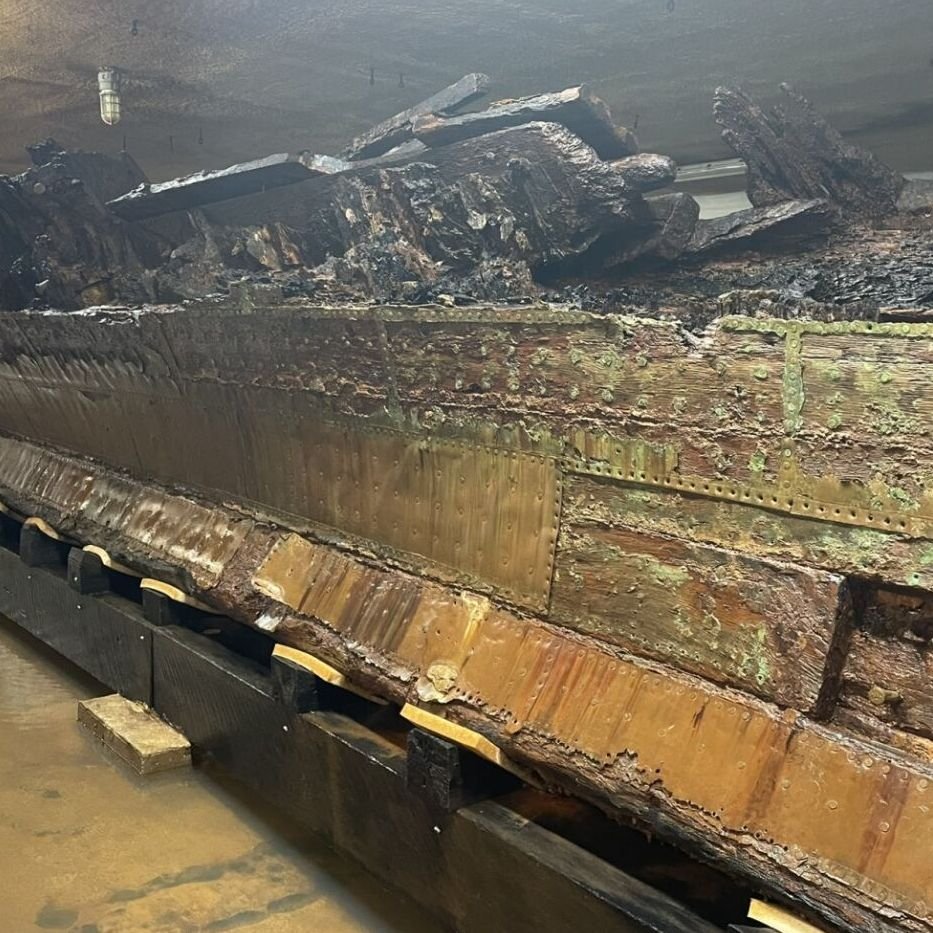
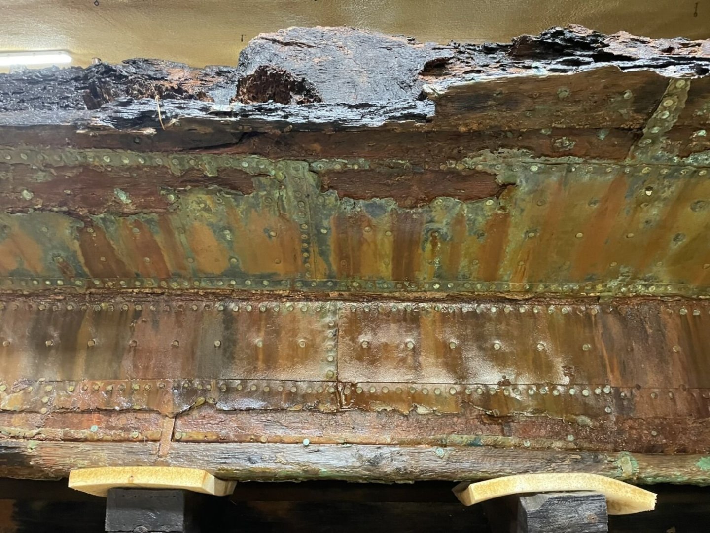
HMS De Braak (or just HMS Braak) was originally built as a cutter in 1781 for the Dutch navy. She was captured in 1795, modified into a brig and taken into the Royal Navy. Her career was short and in 1798 she capsized and sank in Delaware Bay. Recent salvage work has raised a large part of the hull which is now the subject of preservation work. Much of the coppering is intact and is a true contemporary record, not a recent replating such as on USS Constitution or HMS Victory. In my opinion it is most likely to have been applied during her refit in 1795-1797 though there is a possibility that it was applied by the Dutch. Can anyone shed light on this? Pete Stark in the 1805 Club sent me a collection of his photos of De Braak and I have attached some below. Thank you Pete for letting me share them. I recommend that you take a look at the club https://www.1805club.org/ which will be sponsoring the restoration of the ship's bell. 1. A wide view of the raised hull. It looks to me like the keel is near the bottom and the curved planking for the hull is above it. The vertical joins between the plates show that the plate to the left overlaps the plate to the right which indicates that the fore end is to the left and we can see the port side of the hull. 2. The plate at the centre of the next photo reveals the nail pattern. The top edge of this plate has closely spaced nails and it overlaps the plate in the next, higher row. The nail holes in the copper show a trumpet shape, probably formed by the profile of the nail heads. 3. The next photo provides a detail that I did not expect at the join between the hull and the keel: the plates on the hull and the plates on the keel both have a tight row of nails at the edge that is at the join. This suggests that the plates butt against each other and there is no overlap. However, the photo above shows an edge above the tight row of nails at the lower end of the hull plate. Perhaps a narrow copper plate was placed over the join, overlapping the hull plate and possibly underlapping (if that is a word) the plate on the keel. (See also the fourth photo.) 4. The fourth photo shows more of the join between hull and keel but does not answer the question about what plating was placed there, if any. It does look as if the copper went over the main keel but not the false keel - it appears to run into the gap between them. I might be completely wrong about this. I do like the bright, shiny copper with a touch of green verdigris in places. This came from a hull that has been stuck in a sandbank for over 200 years. George Remember to look up the 1805 club https://www.1805club.org/

- 5 replies
-
- 7
-

-

-
- copper plates
- Braak
- (and 1 more)
-
Richard, How much light leaks out of the sides and how much continues to the end? I think that experiments will be the only way to find out. It's not the touchable surface that needs to be rough but the boundary between the fibre core and the clear, cladding layer. The cladding is thin so a bit of sanding should reach through to the core and cause the light to leak out. You might only need to sand on the visible side face of the fibre and leave the face that looks to the ceiling. There is a possibility that you could have a sequence of bright sections (rough surface) linked by dark sections (smooth surface) on one fibre to simulate fluorescent tubes in a long row. Painting the fibres would hide the 'dark' sections and shouldn't affect optical performance. I have had a quick look on Ebay and searched for '1mm plastic optical fiber' which brings up lots of suppliers. Some of them offer 'side glow' fibre but I do not have experience of them. George
-
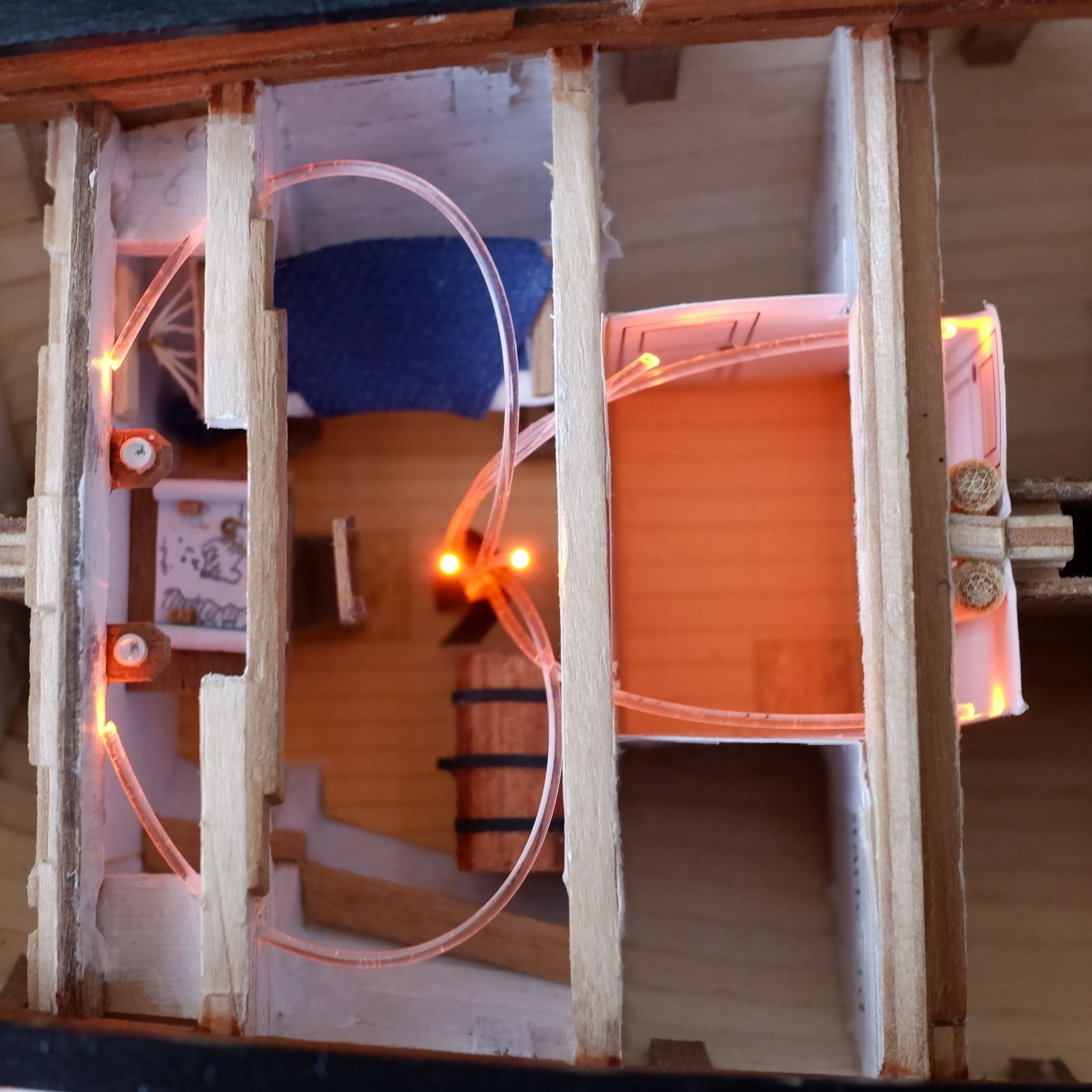
Richard, I have used optical fibres to light the interior of my 1805 schooner model in 1/64. The period and scale are quite different but optical fibres have properties that are useful or a pain, depending on what you are trying to achieve. One is that they leak light if you bend them too much so they have to be routed carefully. A second is that if you roughen the surface the light also leaks out. This might be what you need to simulate your fluorescent tubes. I have used 1mm diameter plastic fibre and arrange seven fibres in a hex pattern to face a 3mm diameter LED. The fibres enter the model through brass tube stands (3mm internal diameter) so they are invisible. This also leaves electronics and solder joints outside the model so they remain accessible. The fibres are readily available on Ebay and cheap so a bit of experimenting could give you a solution. George

-
It was a few years ago and I think that tiny rubber band came from a cocktail umbrella. We had bought a small box of them and each rubber band kept an umbrella closed. George
-
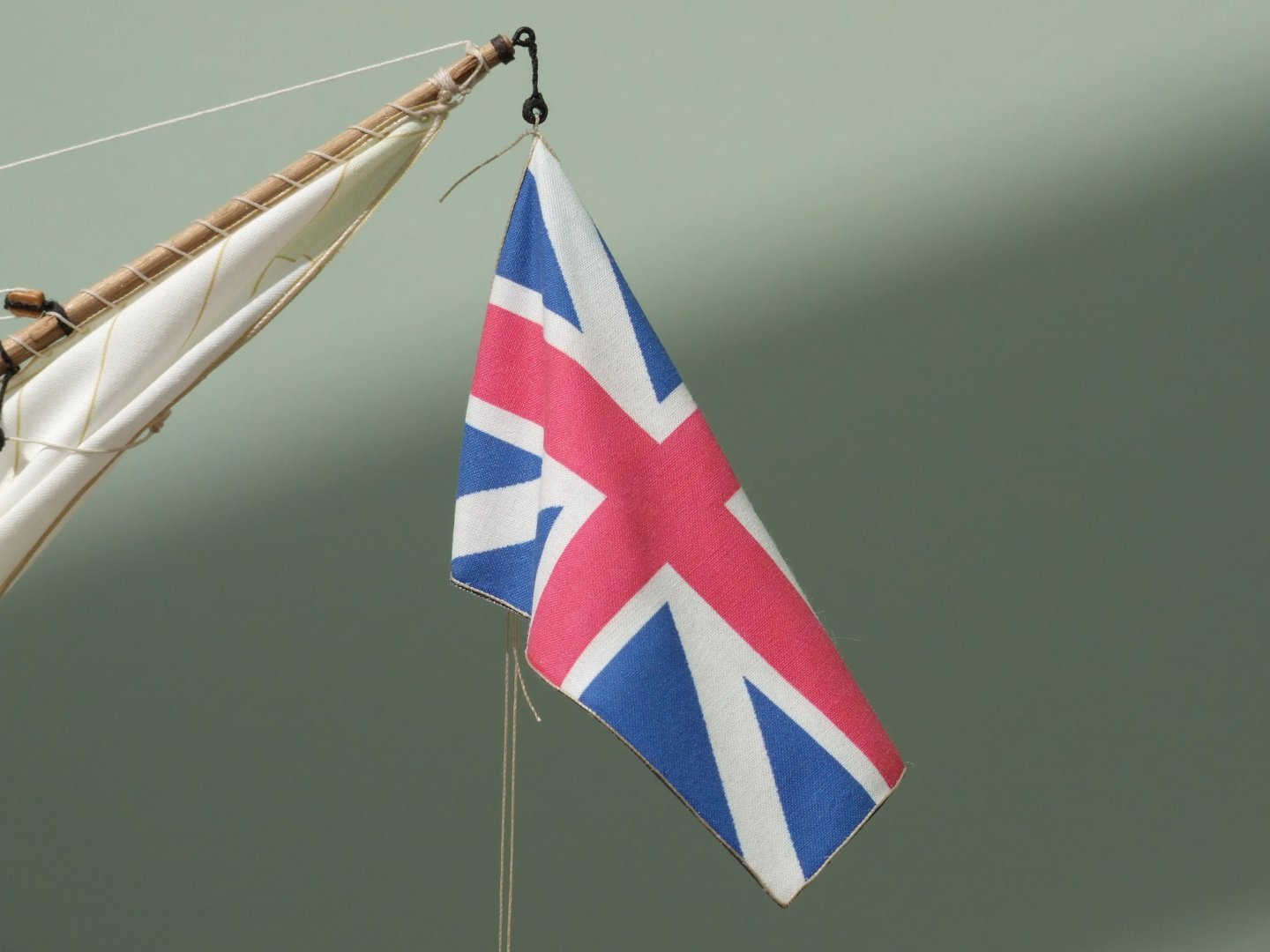
Phil, Congratulations on being on the final straight, it's just irritating that someone keeps moving the finishing line a bit farther away. You'll get to cross it some day soon. Anchor nun buoy. I made one for my Sherbourne cutter from plastic left-over bits. Think model aircraft drop tanks, bombs, pen tops, there are lots of things that take you along the way. The trickier part is to create the ropes and hoops that all go over each other. The attached pdf is about anchors and describes the buoy in more detail. Anchors.pdf The difficult question is where to store a buoy and its rope. Tying the buoy to the shrouds is reasonable though it would take several sailors to lift it while one ties the first knot. I cannot really imagine where else it could go on a schooner with cramped accommodation below. The rope from the buoy to the anchor is 17 to 18 fathoms (Lever page 68) which on your 1/48 model is well over two feet. That is a big, unwieldy coil to hoist up on the shrouds and then tie in place. Could the rope be kept in the cable tier and spliced or hitched on when needed? Flags. I spent time with a hand towel looking to see how it would hang. Hold it up by one corner and pull another corner so that a short edge hangs vertically. You can now play with folds in the towel/flag to bring forward the bits you want to show. The critical feature is that some of the flag (ideally 50%) falls forward of the halyard; if you want the flag to be fluttering to one side of the halyard then gravity will win and the short 'vertical' edge will hang at an angle unless you put on a scary amount of tension. I will be laser printing onto tissue (teabag paper) later this year when I start on the sails for Whiting. Like you, I am concerned that sticky tape will ruin the fuser in the printer if I have to attach the tissue to stiffer paper. A fall back method that I am considering is to glue the edge of the tissue with a glue stick (Pritt stick in UK). I don't know if anyone else has tried that here, or experimented with different tapes. You could run some trials with that small iron you use for bending planks. George
-
Phil, I understand your last post and agree that there are choices to make about the level of detail to include on a model. I also ignore trenails but others like to include them. I have copper plated the hull with Amati parts which have representations of nail holes because to my eye plain ones look as if something is missing. My most extreme inclusion is probably the furniture in the captain's cabin on Whiting which is only just visible through a skylight. Methods for serving a rope is something that I have been experimenting on and at present I rely on thick paint; I doubt if the turns of a serving line would be visible at normal viewing distance in 1/64. But if I make myself a serving machine then I might change my mind. To me a joy of the hobby and this forum is that people make their own choices and accept that others can follow different paths. George