georgeband
-
Posts
307 -
Joined
-
Last visited
Content Type
Profiles
Forums
Gallery
Events
Everything posted by georgeband
-
 Bit of a gap since I last posted. I have been busy with Whiting but it has mostly been research for the sails and rigging which is in a separate post. https://modelshipworld.com/topic/31489-reef-a-gaff-sail/ I now have a spreadsheet with about 130 lines, one for each rope that I can think of, and notes from Marquardt, Petersson, and others about which way a rope is routed and where it is belayed. The rate of evolution has slowed now so I am probably close to reaching my first proper version. When the spreadsheet is complete I can derive a belaying plan with confidence that there will be enough cleats and belaying pins and eyes. There will also be a shopping list for blocks and other bits. Actual model making has ground to a halt and will remain quiet during the summer season when full size activities on house and garden take priority. George
 -
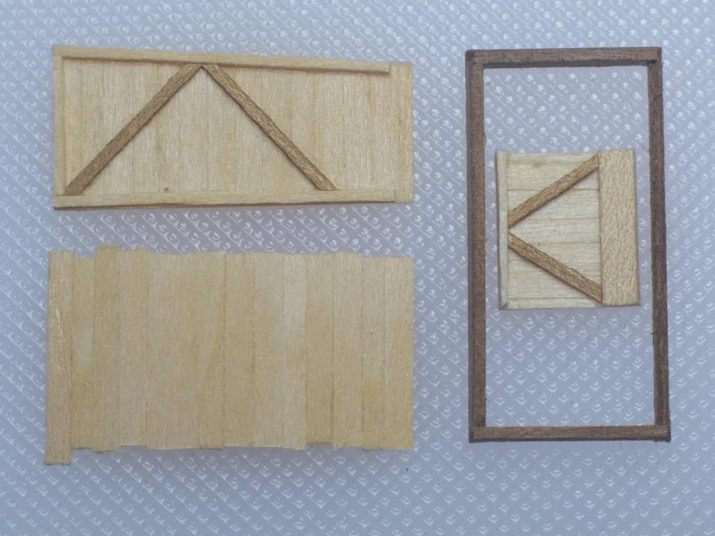
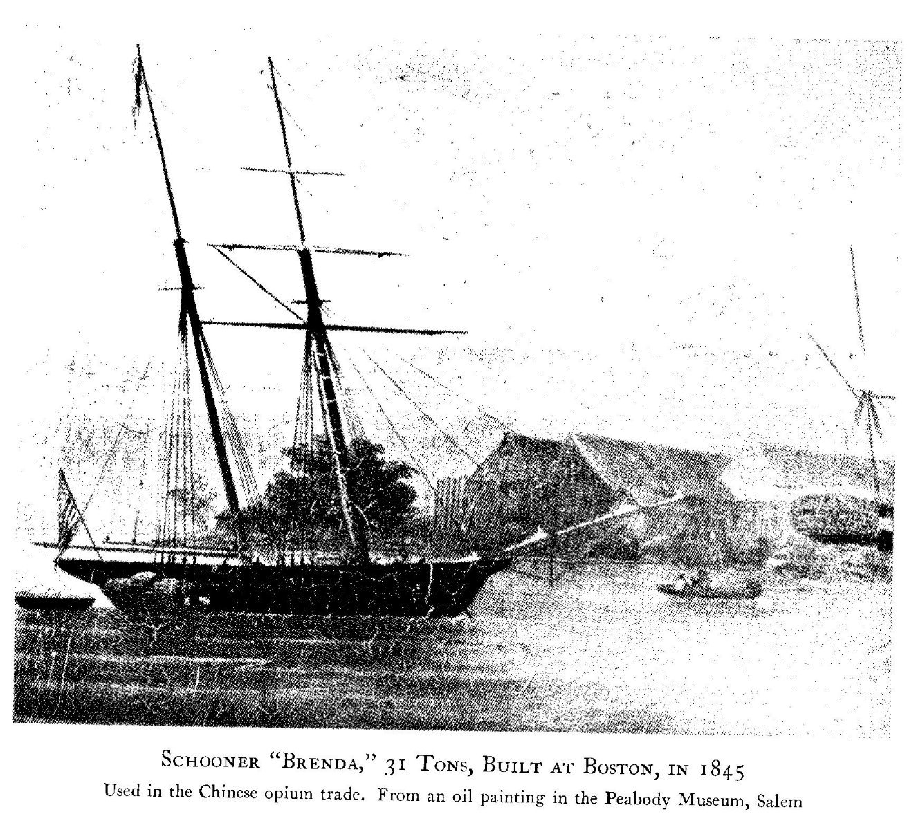
Gaskets and furling The discussions earlier in this thread touched on furling as well as reefing and I would ask for assistance about gaskets. For a square sail the first stage of furling (brailing, clewing) gathers the sail loosely below the yard. It is then pulled up 'accordion style' and the final layer of canvas wraps around the bulk of the sail. Gaskets are looped around the sail and yard to hold everything tightly in place. Drawings rarely show the gaskets but sources such as Falconer describe how they are made and used. For gaff sails the furling is similar. Falconer says that furling can be to a stay or mast and I would expect the guiding principle to be the same as for square sails - create a tight bundle that the wind cannot tear open. Lots of paintings and photos show a brailed gaff which is the first, loose gathering of the sail. Sources such as Lever agree that there were typically two or three brails for a sail and this is supported in the pictures. The final, tight furl is less commonly seen and the example below is from Chapelle's Baltimore Clipper (opposite page 142). The main (aft) gaff sail is sandwiched between the boom and the gaff which has been lowered to meet it. There look to be some features on the furled sail but I cannot discern what they are. (That shore line complicates the interpretation.) The fore gaff sail does not have a boom and has been furled to the gaff yard and the mast. We can see the hoops around the mast but again the details of the final furling are poorly resolved. There may be something wound around the mast and sail to hold it together but I am not sure from this picture. My assumption for modelling is that there would be gaskets to tie the sail to its yard or mast. If the sail is open then I presume the gaskets would either hang loose or hang in a coil. The questions then are how many gaskets and where do they attach to the sails? Sail with gaff and boom. The gaskets are probably tied to the top of the sail by the gaff and are accessible from deck when furling. I guess that there might be two or three of them. Sail with no boom. Two or three gaskets would hold the sail to the mast. I have not seen horses below the gaff yard so I expect that there are no gaskets along the gaff and we rely on the brails to pull the top part of the sail taut. Does anyone have information to add to this? George


-
Thanks everyone for your practical insights which show how this issue can be solved on some craft in some periods. However, the Berbice problem still haunts me and I cannot see how that fore gaff sail would be reefed without step ladders or extreme acrobatics to reach the reef points. This is when I change from scientist to engineer and devise a practical solution for Whiting for which we do not have good information and can make our own choices. The fore gaff sail on my Whiting will Have a gaff yard that can be lowered Lacing on the mast which can be unrove (if that is the right term) from the lower end if the sail is reefed and lowered Some way to hook a tack to the fore edge of the sail when it is reefed. The illustrations of gaff sails that I have seen have a reef cringle at the ends of each reef band and this might be the way to do it Some way to hook the sheet to the aft edge of the sail when it is reefed, probably though a reef cringle again Brails for brailing Some ropes to tie the furled sail to the mast, equivalent to the gaskets on a square sail. These could also attach to the reef cringles on either the fore or aft edge or both. Can you point out the flaws in this plan and put forward improvements? George
-
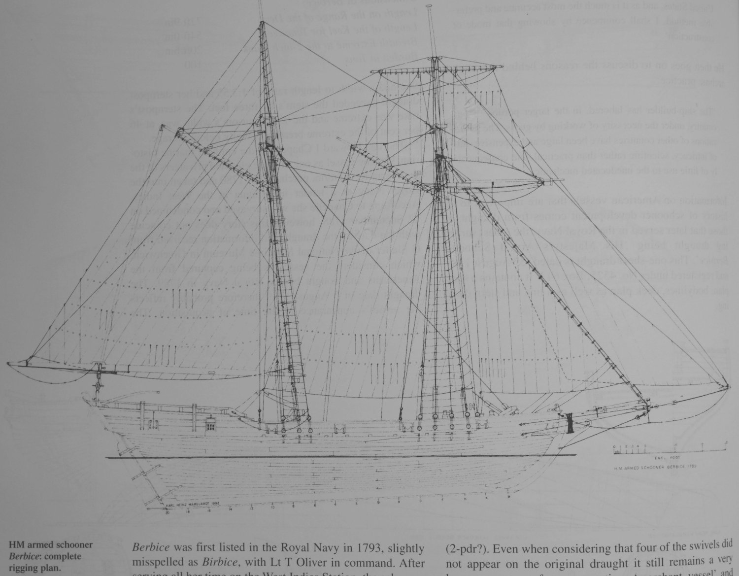
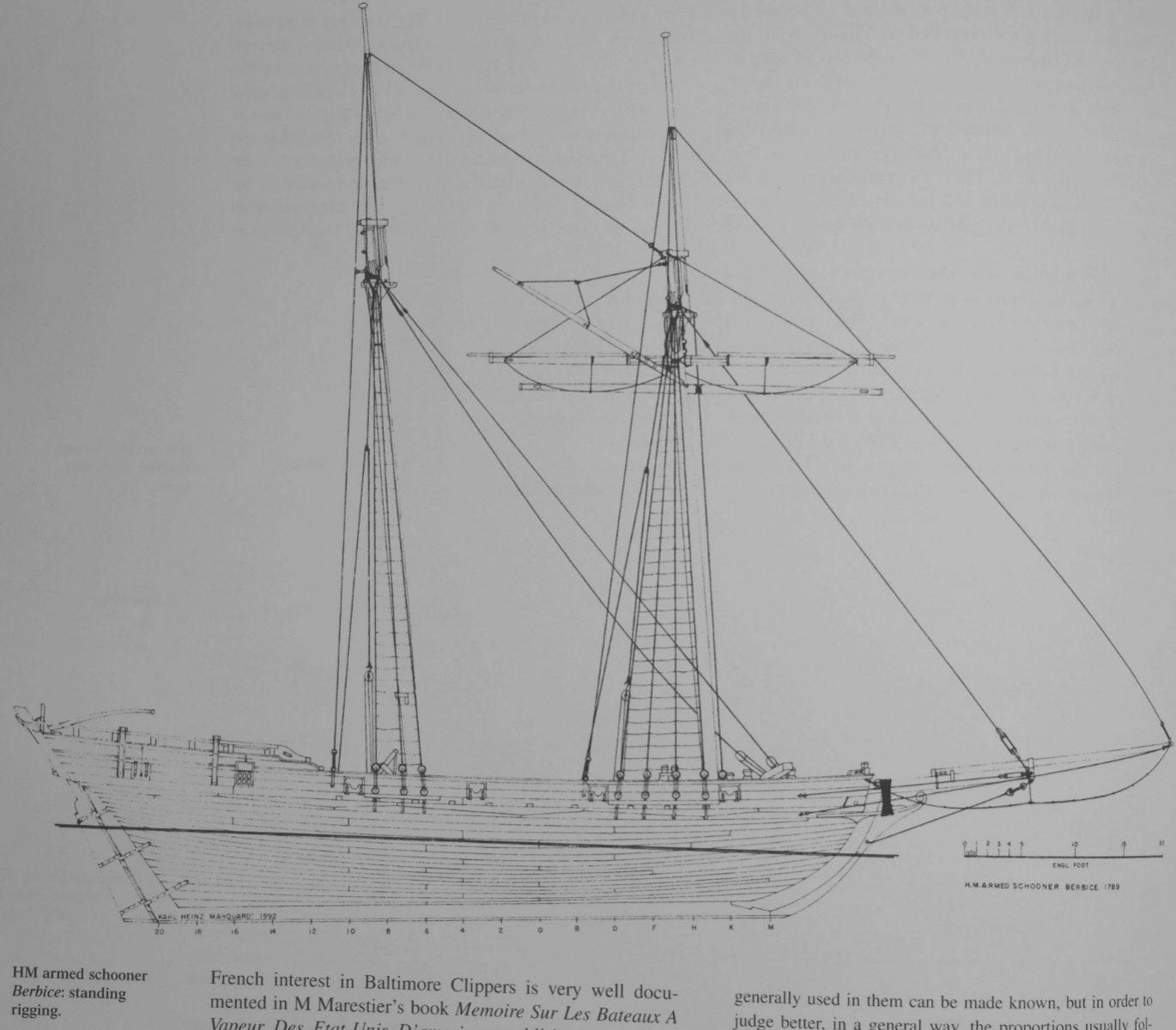
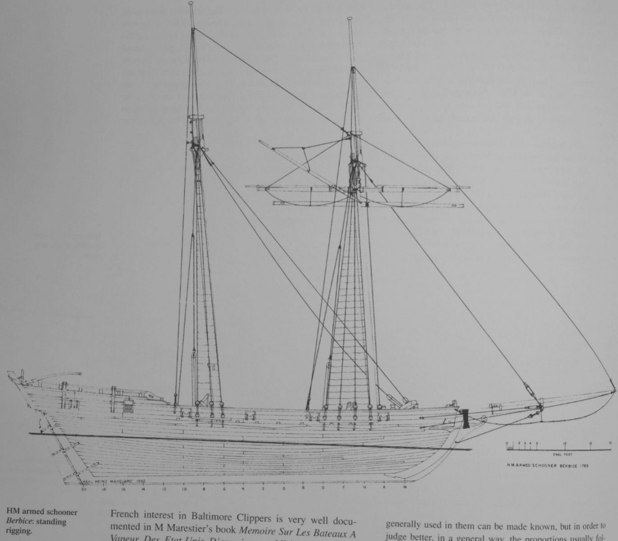
Phil, I am sorry that I have to disagree with some of your statements here. My knowledge comes from what I have read in Marquardt, Chapelle, Lever, Petrejus and others and fundamentally I agree that schooner rigs were not consistent, though some arrangements were more common than others. A little on terminology. Furling or handing refers to securing a sail in a safe, unused state on the yard or mast. Brailing, according to Falconer, is a preliminary stage of furling when a sail is gathered up. Reefing is reducing the area of a sail in strong winds. For square sails the reef points are usually near the top and are tied over the yard. For gaff sails the reef points are usually near the bottom and the sail is gathered by them. Gaff sails are laced or otherwise tied to the gaff yard at the top. The leading edge is secured to the mast by hoops or more lacing. The clew at the lower, aft end is fixed to the boom if there is one. If there is no boom then the sheet is secured to a cleat via some arrangement of blocks. The lower edge of the gaff sail, as far as I know, was not laced to the boom but it might be different in current practice. Phil's photo of Pride of Baltimore II shows the main (aft) gaff sail straining at the clew where it is attached to the boom. The sails on the fore mast have been brailed, though technically the topsail might be 'clewed up'. To reef a gaff that also has a boom the sail was lowered until the reef points could be reached and tied together. To furl the sail it was lowered further until the gaff reached the boom and there are paintings that show this. Marquardt and others describe this well. Brailing was 'sometimes' used for a gaff when there is a boom, but apparently was not normal practice. To reef a gaff that does not have a boom, the sail was similarly lowered and the reef points tied together. Furling was a different action and Phil's photos show it well. My original questions still stand. If the gaff is laced to the mast does this prevent it from being lowered? If the gaff is fixed and cannot be lowered, how do the sailors reach the reefs? The answer might be that current drawings are mistaken, but I suspect it is that my knowledge of reefing is simply inadequate. The two pictures below are of Berbice from Marquardt's Global Schooner. They show Reef bands on the sails Lacing around fore mast and hoops around main mast Standing rigging to hold the fore gaff - it did not have blocks to adjust the height Main gaff sail is not laced to the boom. George

-
A lot of the drawings for schooners and other vessels show a gaff sail with a boom below it. The sail is laced to the gaff and joined to the mast by hoops. To reef the sail I assume that the gaff is lowered and the reef pendants are pulled until a reef band reaches the boom, at which time the sailors reach up and tie the reef points together to shorten the sail. So far so easy, in principle, though I don't doubt the sailors' strength and courage when it was wet and windy and dark. The fore gaff sail on a schooner does not usually have a boom and appears to be laced to the gaff yard and to the fore mast. The gaff itself is often fixed and cannot be lowered or dipped. There are lots of example drawings in Marquardt's Global Schooner and one I have in front of me is HMS Berbice (pp 42-45). The sail has two reef bands so it can be reefed, but I cannot see how this would be done. The sail cannot be lowered because of the rigging of the gaff yard and the lacing on the mast. To raise the lower edge by reefing, the lower part of the sail would have to lifted and again the lacing makes this difficult. There is the added complication that the sailors would need step ladders to reach up to the reef bands. In Chapelle's Baltimore Clipper the line drawings do not show hoops or lacing. However, the copies of contemporary paintings often show the fore gaff to have hoops joining it to the mast in the same way as the main gaff. I cannot see whether the gaffs are fixed or moving; it is probably more likely that they can be lowered otherwise why have mast hoops? I suspect that Marquardt's drawings have adopted a convention, though they could describe a reality. It all depends on how the fore gaff sails were reefed. Does anyone know? George
-
sail plan for Ballahoo (Fish class) topsail schooner
georgeband replied to georgeband's topic in Masting, rigging and sails
After a pleasant diversion when I have actually been making the deck furniture on Whiting I return to the sail plan. The reason is that I have to understand the rigging plans so that I can put eyes and pinrails and cleats in the right places. I have read through my transcriptions from John Roach's log again, and expanded them, and old doubts and uncertainties have resurfaced. Log book Remarks for September 16th 1806 Fresh gales and squally close reef'd the foresail, got the jib boom in and reef'd the Jib At 4 Do.W. [same weather] sent? down the jib took the mainsail in & set the main try sail at 6 Fresh breezes reef'd the main topsail… The log book often refers to a 'fore sail'. My assumption was that this is the large gaff sail on the fore mast and not the course or lower square sail. I now realise that this was an assumption and that 'fore sail' could be the course, or the gaff, or either depending on what Sub-Lieut Roach thought at the time. The fore sail could be double reefed and this is consistent with a course. It is also consistent with a gaff sail if it has hoops around the mast so it can be lowered, and according to Marquardt this was less common for the fore gaff which did not have a boom. In an earlier post I mentioned the lower studding sail which could be a water sail, or it could sit next to the course. So was the 'fore sail' a gaff, a course, or either? Reefing the jib is quite understandable if it rides on a stay and many illustrations show reef points on a jib or stay sail. The entry for 19 September says put the Bonnet on the Jib which I was not expecting because it seems to ask a lot of the jib sail to reef it and extend it. But who am I to judge with zero experience of sailing a schooner? I am puzzled by reefed the main topsail. There are other references to a gaff top sail which I take to be on the main mast and I have not seen illustrations of one with reef points on it. Even if it did have reef points it would be suicidal for a crew to try to reef it unless the sail and yard were properly set up for this activity. Was there another, square topsail on the main mast? Or did Roach make a mistake in his hurry to complete the log? Or have I misread it? Help! George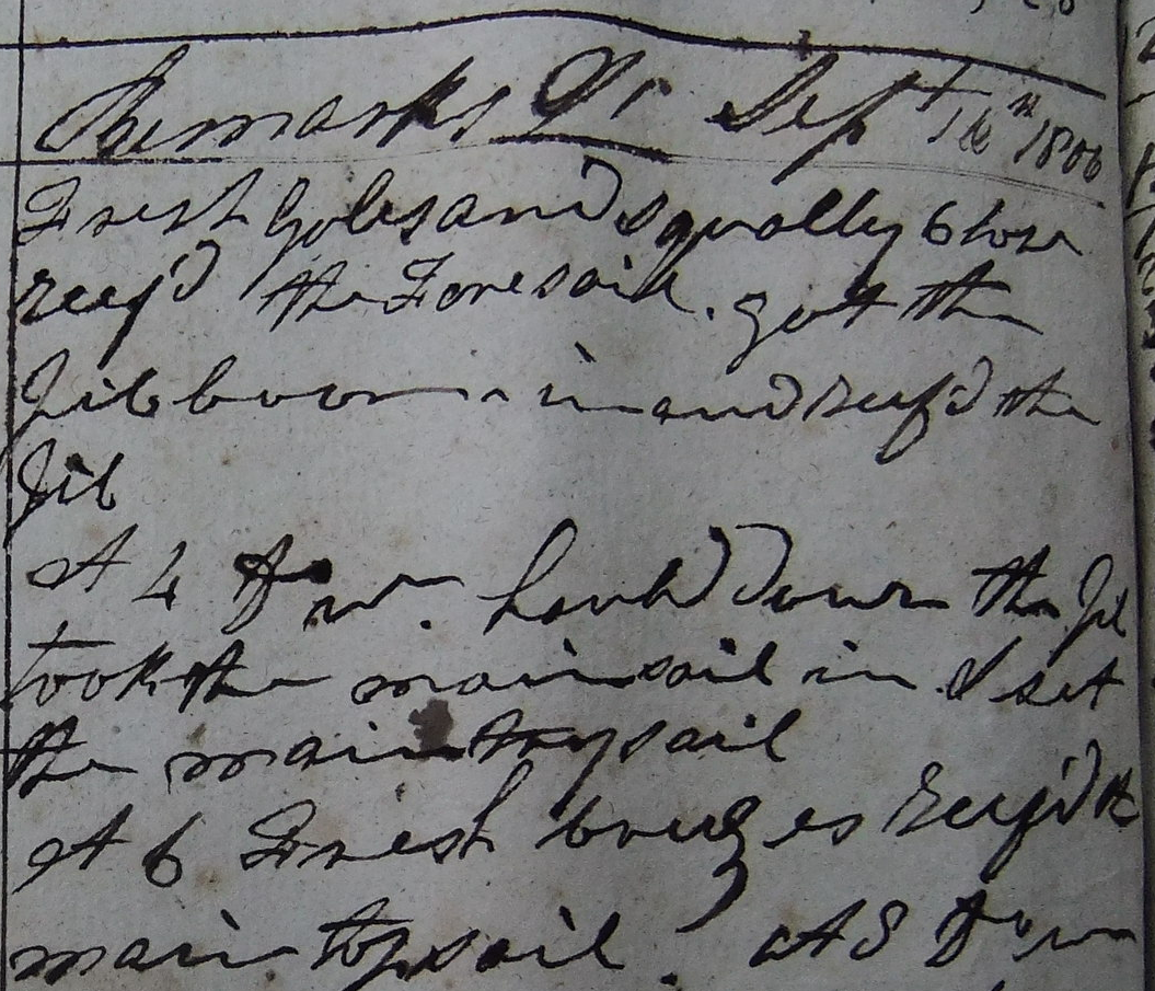
- 22 replies
-
- 3
-

-
- caldercraft
- jotika
- (and 4 more)
-
I would keep going in sequence and put the garboard strake in last. It is tricky to fit the last plank wherever it sits but the garboard is, in my opinion, the less difficult to trim to shape. Be prepared for stealers now. At the bow you will find that the tapers go to a point and fall short of the stem post unless you do something smart. Similarly at the stern you will find gaps between the planks that need to be filled. Simple triangles will do at the stern or you can try to follow real practice. (If you are painting the hull below the waterline no one will know if you take some shortcuts.) George
- 65 replies
-
- 1
-
-
- Ballahoo
- Caldercraft
- (and 1 more)
-
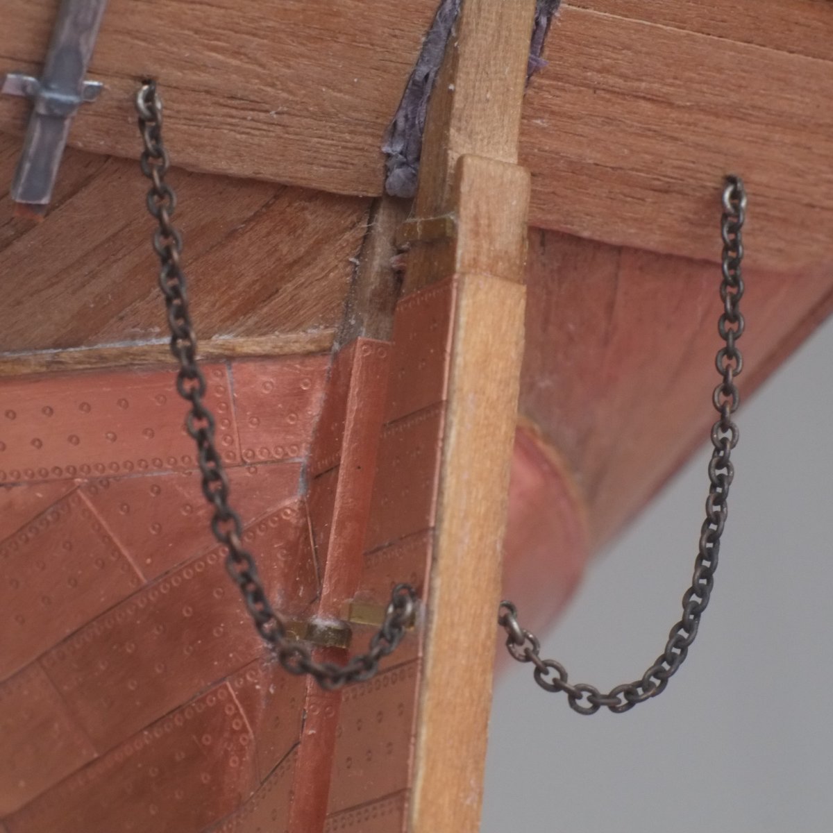
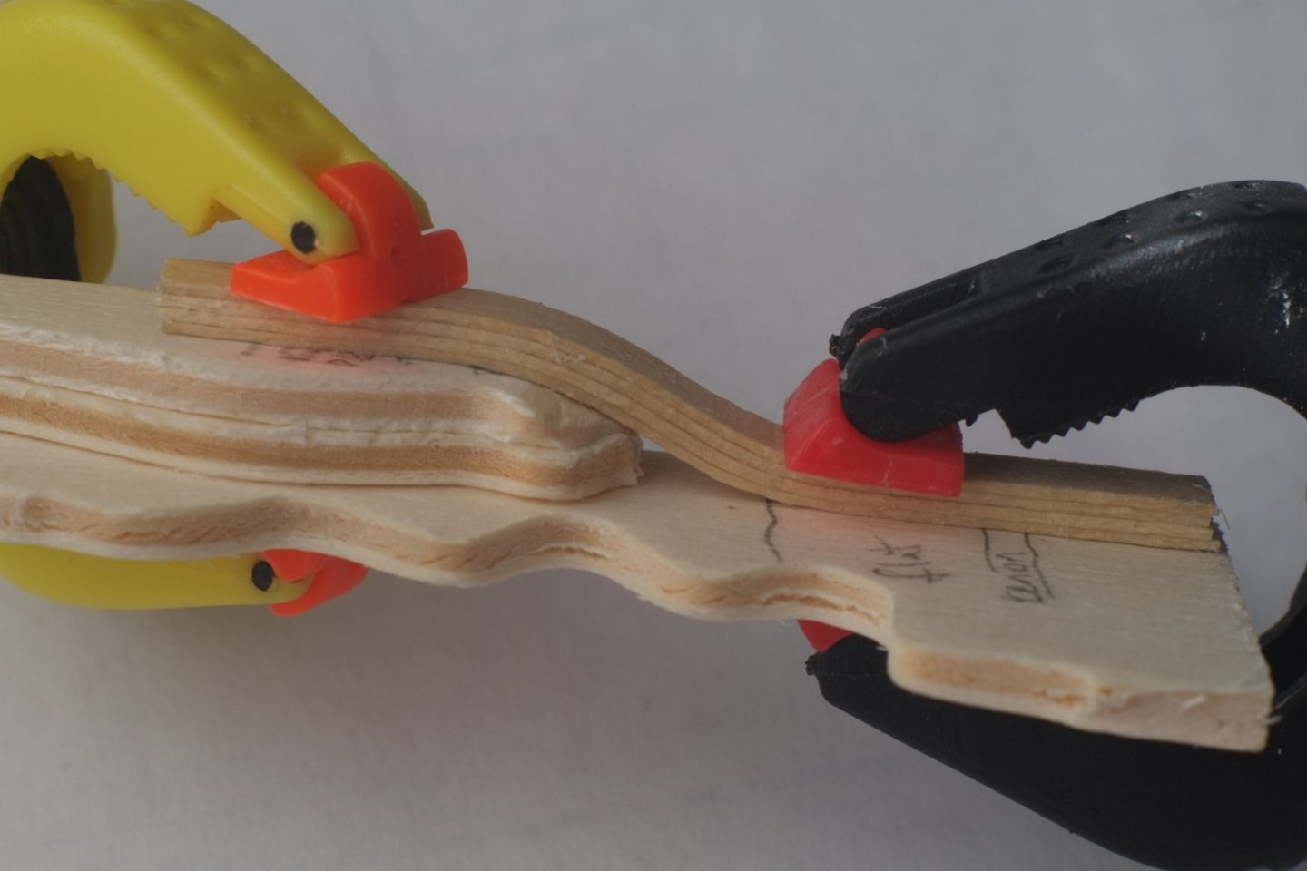
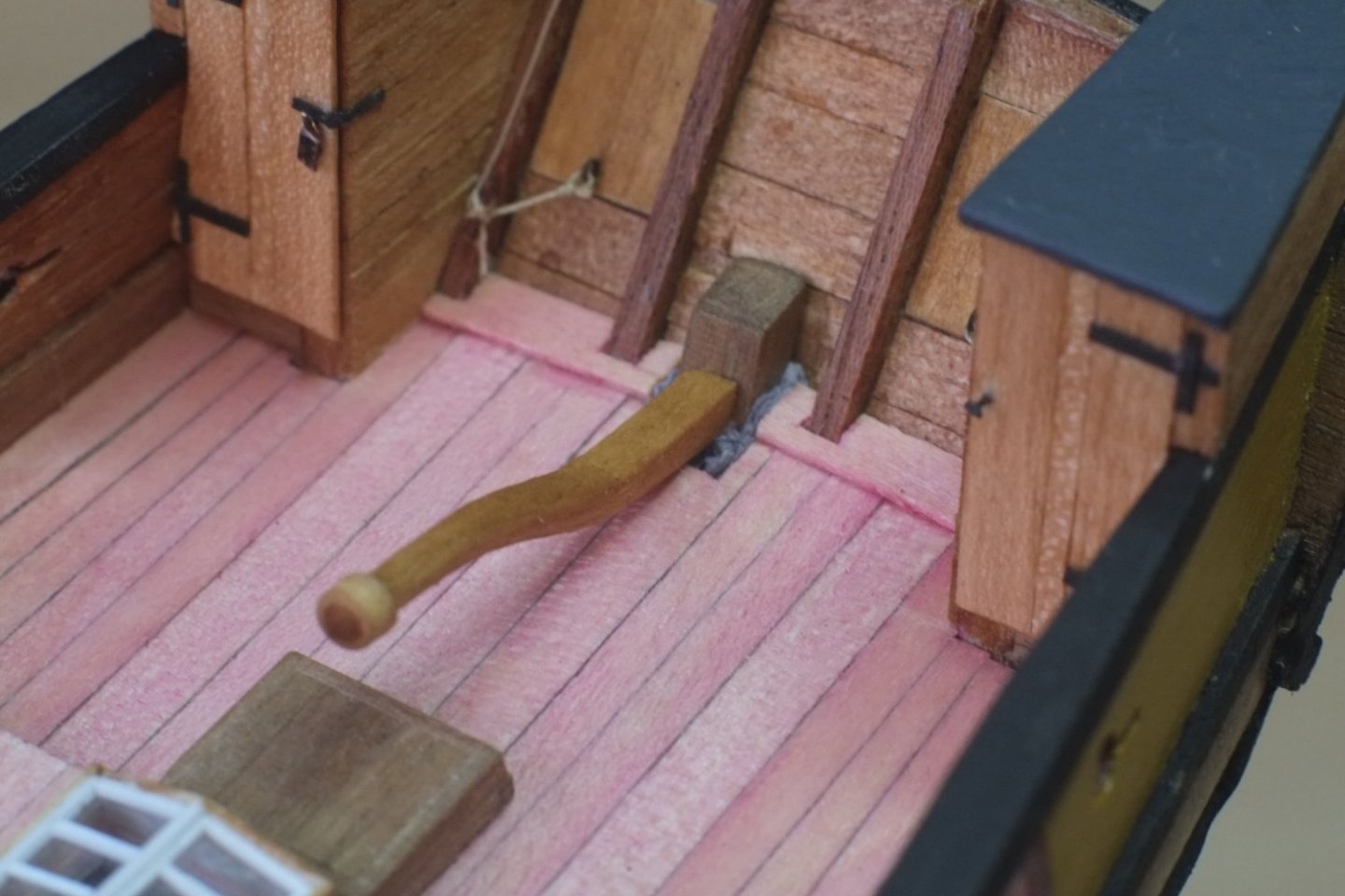
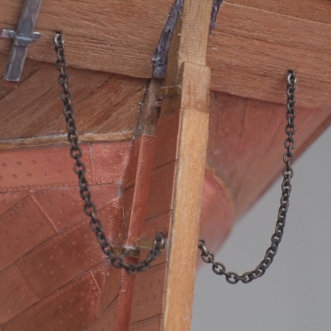
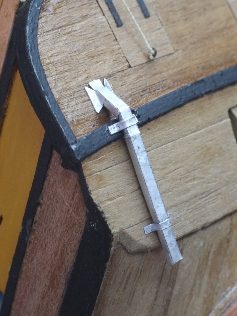
Thank you, Tony, for your kind words and reminding us where to find the discussion about binnacles. Thanks to all for 'likes' which are a real morale booster. Rudder I described construction of the rudder in earlier posts when I was coppering the hull and it has now been finished and mounted. Tiller The tiller is curved in an elongated S shape and I made mine from a laminate of 0.5mm thick planks. The former for the laminations is from scrap ply (actually left overs from a dinosaur kit that I made with my 4-year old grandson). When the glue had set I sanded the width to get a 2x2mm section and then carved away at the back end to make a round tenon. The front merges into a circular section but it could have been square in reality. The knob at the front, which is shown on the Admiralty drawings, is from paper wrapped around the the wood. I stained the whole thing a walnut colour to match the rest of the model. Laminations for the tiller. The curvy edge in the ply former is where the dinosaur's teeth were Tiller mounted on the rudder. The grey stuff around the rudder head represents tarred canvas which stopped water going down into the hull. I used tissue paper, stained grey and glued with PVA Chains The chains were to stop the rudder from sinking if it was knocked off its pintles. The hardest part was fitting an end link in a chain into an opened ring, and an eye into the same ring, and then closing the ring. The links are 1mm long. Having fitted the chains I am now wondering if they should be brass rather than 'iron' to prevent the iron from rotting away through electrolysis. I am sure that brass chains would have been more expensive and expect that the Admiralty would have saved money in the short term by ordering iron instead, so I will leave mine black. Rudder chains, and more tarred canvas around the head of the rudder. The soil pipe below the necessary has been dabbed with grey paint to give it a duller finish George
-
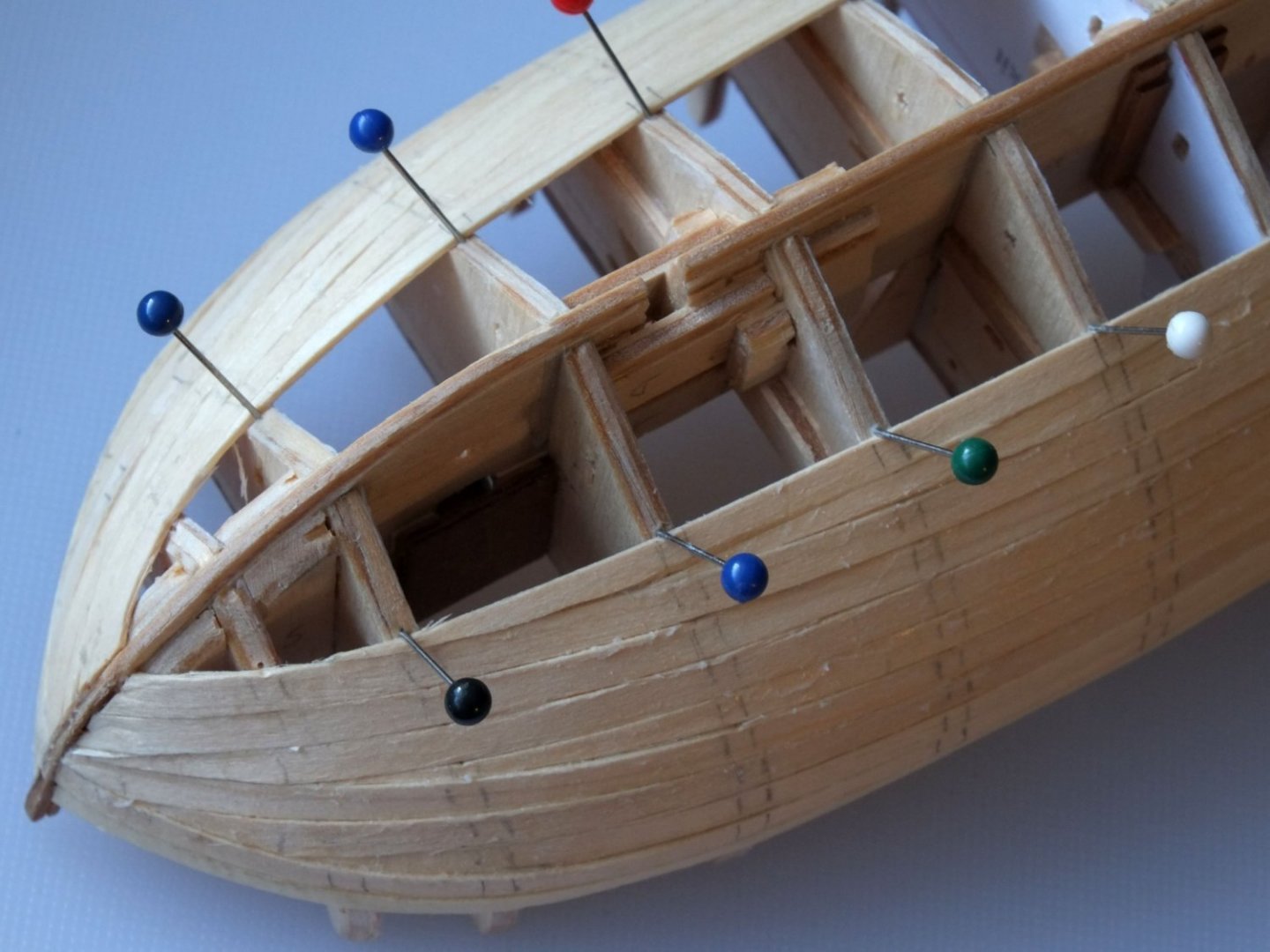
That's a smart use of clips, Gregg, especially the way the spring holds the plank down. Thanks for sharing. For the planks near the keel and for the second planking there is no bulkhead to grab on to and I suggest a pin pushed into each bulkhead. If you angle the pin next to the plank it presses the plank down and against its neighbour. Don't push the pin through the plank because you risk splitting it and you also end up with holes to fill. If you go ahead with this method then put pencil marks on your first planking to show where the bulkheads are underneath them. Many will get sanded off but it is easy to do for each plank as you lay it and the remaining marks can be joined up, ready to guide the pins for your second planking. George
- 65 replies
-
- 5
-
-
- Ballahoo
- Caldercraft
- (and 1 more)
-
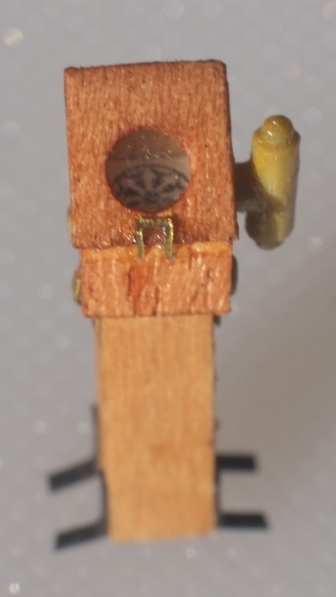
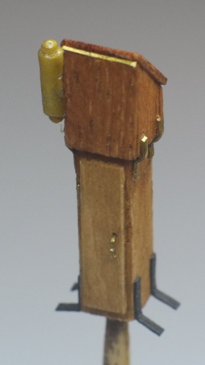
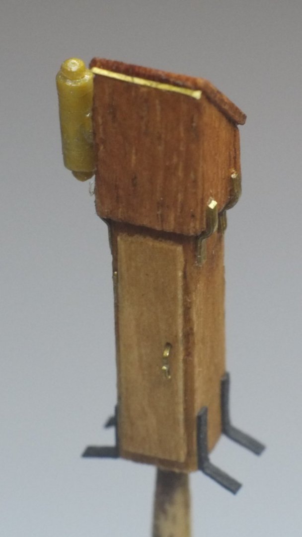
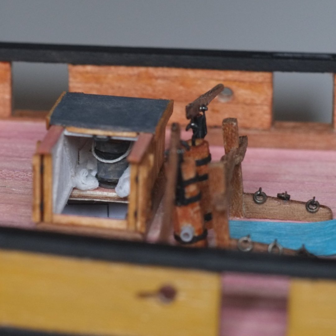
Pieter, Thanks for your comment about toning down the colour. I will see first if acrylic paint adheres to the foil, otherwise I will have to open up a tin of Humbrol enamel. I will try it out on some remaining foil before venturing on to the pipe. Binnacle Next piece of building is the compass in its binnacle on a stand. The standard three-compartment binnacle used in the Royal Navy looks too big and there is an interesting comment in John Roach's log book for 17 June 1806 which states 'Try'd the compasses and found the one in the Binnacle to Err one point from the other owing to some Iron thing near it'. This shows that the binnacle housed only one compass; the second was probably a boat compass in a box. An internet search for 'antique binnacle' soon reveals smaller binnacles that have one compartment with the compass and a light attached to the side. There are two varieties, one made of wood and a domed, brass one which looks like a helmet for a Victorian astronaut. (Binnacles with two iron balls on them did not appear until the 1880's.) Tony (tkay11) showed on an earlier thread that making a brass dome with a window is very difficult so I chose the wood option. This is similar to the one I made for Sherbourne years ago. The stand for the binnacle is a 15mm length of 4x4mm wood with the ends cut square. I drew and printed a compass card and glued it to one end which became the top. I used 0.5mm thick wood to build a hood with a sloping lid. The lid was glued to paper for strength before I drilled and filed a hole in it, about 3mm diameter. The paper was then scraped off and a piece of clear plastic was glued on. The lid is then glued to the hood. The one remaining wood part is a cupboard door, 0.5mm thick, that I glued to the rear face of the stand on the assumption that something would be stored inside there. The hood was stained a mahogany colour which resembles several of the antique binnacles. The stand and cupboard were stained to match most of the hull woodwork. The lamp on the side was from scrap plastic, painted to look like aged brass. The assembly was then adorned with small pieces of etched brass for hinges and clamps and handles, and black paper for feet to secure it to the deck. Front view of the binnacle with the compass card visible through the window. Rear view of the binnacle. The stand is only 4mm wide so please excuse the magnified errors George

-
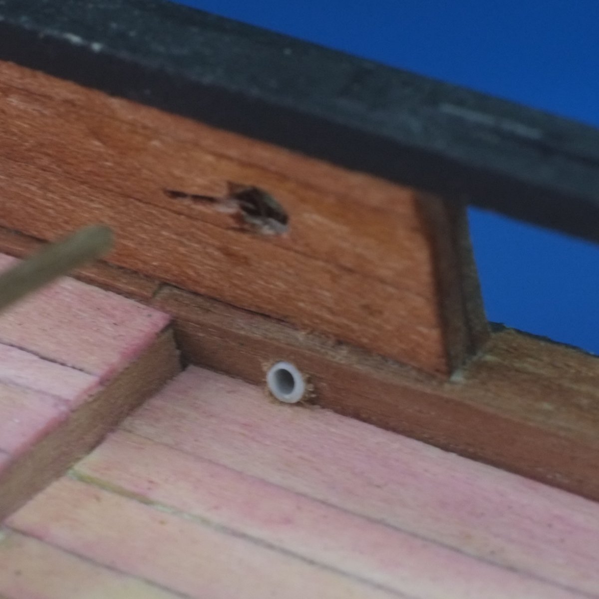
A couple of photos of a scupper, inboard and outboard. These are somewhat magnified and the furry edges of the wood and other horrors are not visible to the naked eye. Scupper inboard near a step in the deck Scupper outboard just below a wale One other job I have completed is the outlet pipe from the necessary. There is a good review of shipboard toilet arrangements in an MA thesis by Simmons which you can find on the web, or just here. Seats of Ease Simmons-MA1985.pdf The pipe was usually made of wood or lead and I thought a metal one would look better. The model part started as a former in 1.5mm square section wood which had a couple of joints to take it down past the counter. I then gave it a coat of aluminium from a foil wine bottle cap which I folded around and glued with CA. A couple of brackets from the same foil make a pretence at holding it in place. The aluminium is a little bright and I might tone it down later with a grey wash. What do you think? Soil pipe below the necessary George

-
Gregg, Planking gets easier with practice as you learn the techniques that work for you. Have you been pre-bending the planks before gluing, or do you rely on the glue to hold them in place? The various build logs describe different ways of bending (dry heat, wet, or hot and wet) and the difficulties of bending a plank across its width rather than the easy way across its thickness. Have a go with the first planking and then the second layer will be less daunting. Any gaps between the planks, or between the first plank and the bulwark, will haunt you later. Glue an offcut of the planks inside the hull to cover the gap from behind and you will then be able to fill it before sanding. Better still to bend and shape the planks to close the gaps so they do not form. Tapering the planks (adjusting the width) is even more important than chamfering the edges (cutting an angle on them) to get a really tight fit. 'Bevelling' to me suggests chamfering though you might mean tapering, or it could be that the meanings change across the Atlantic. I am probably at the slow end of the speed building spectrum and some planks take me half an hour to prepare before gluing. Ten minutes for an 'easy' plank is a pleasant surprise! Take your time and enjoy the hobby. George
-
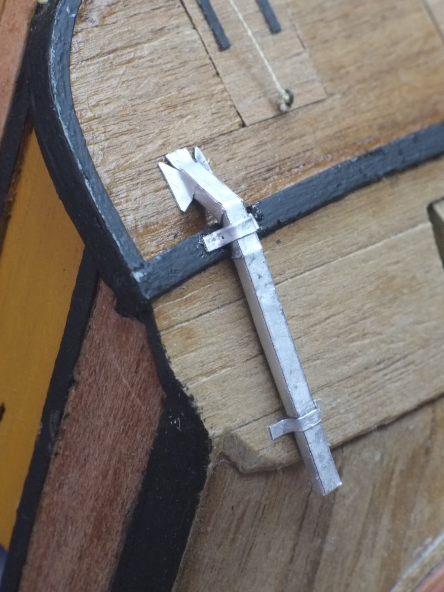
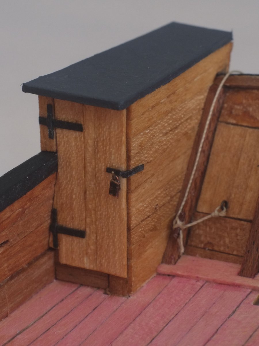
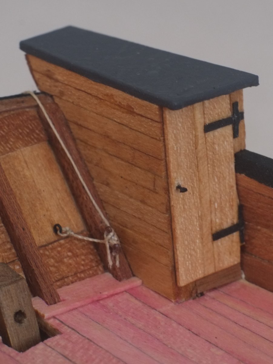
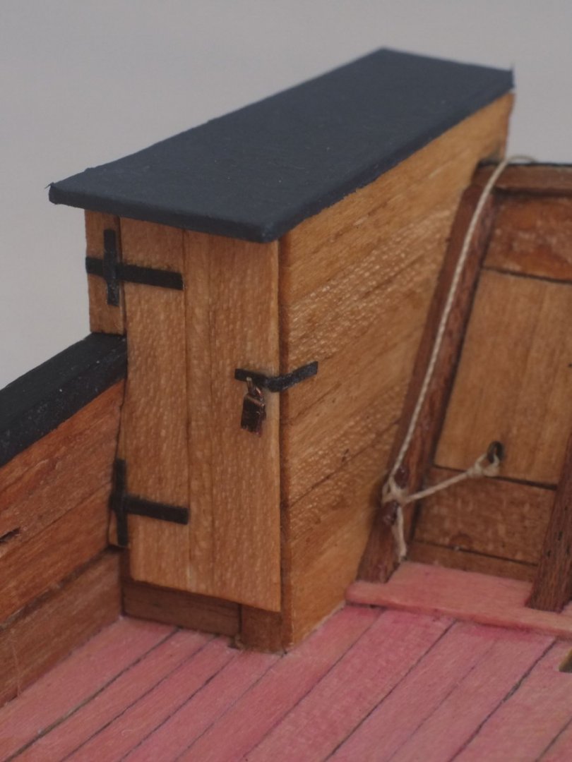
Pantry and necessary These two structures at the stern are clearly marked on the Admiralty drawings but there is little detail about them so I have relied on imagination and judgment to guess how they were built. The model build has two stages to it. First is making a foundation structure from ply and bits of scrap wood, second is planking the external surfaces and making a roof. I used kit deck planks (split down to 2mm wide mostly), and the roof is ply and paper painted to look like tarred canvas. The hinges and bolts were paper and oddments of wire and brass. I also tied off the ropes from the stern port lids to small cleats that I made from wire. Ply structure for the pantry The pantry, with a padlock to keep thieving hands out The necessary, with a simple latch to keep the door closed One other little job was to drill holes in the bulwark waterways for scuppers. I put one at the bottom of the step at each end of the captain's cabin and one further forward. A short length of grey plastic pipe, 1.5mm outer diameter, is a push fit into the holes and represents a lead lining. George

-
The finished port lids are now posted on my build log for Whiting. It is now too late for a revelation to show what I should have done! George
-
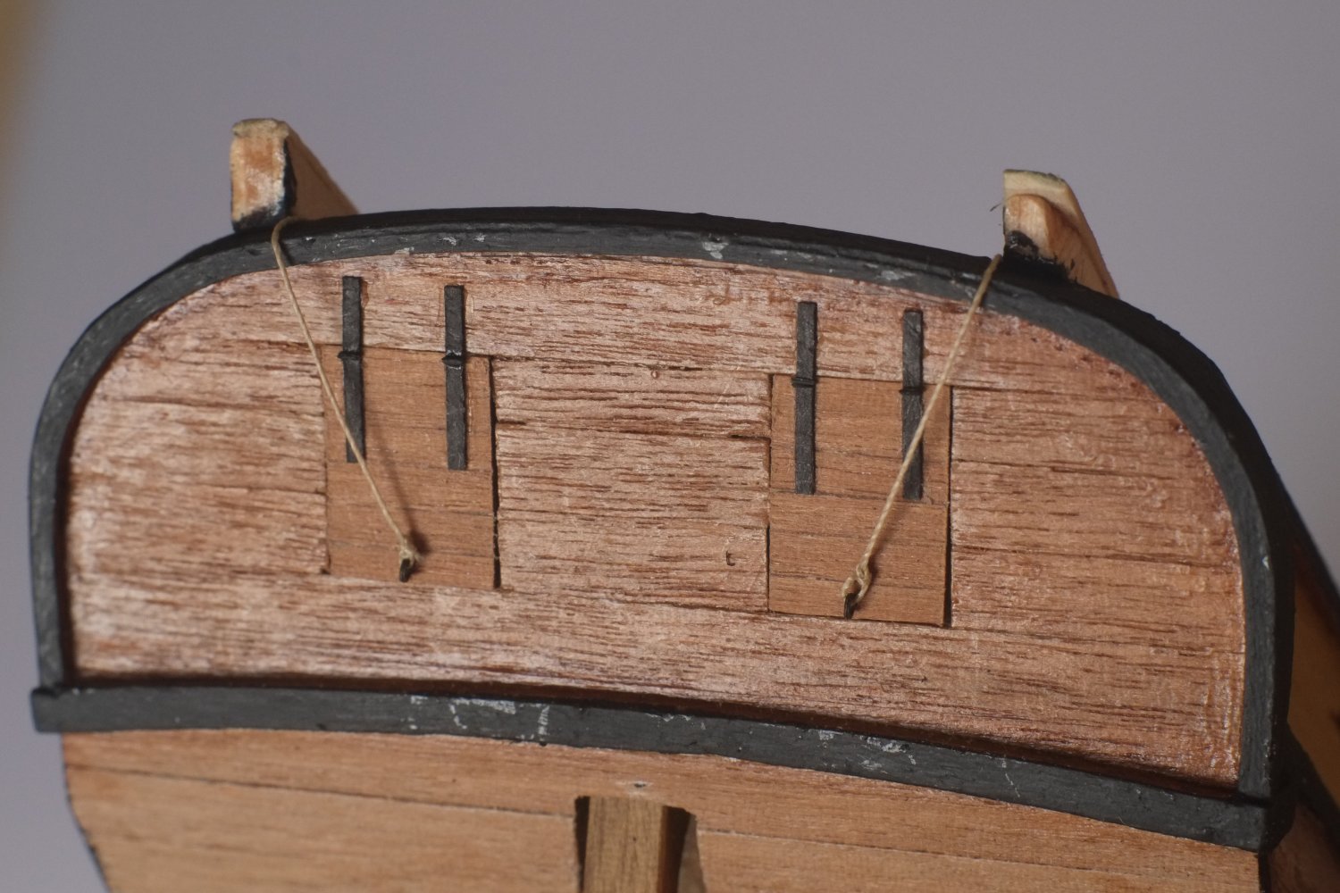
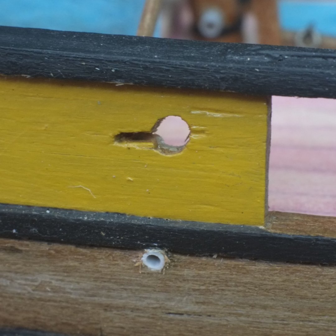
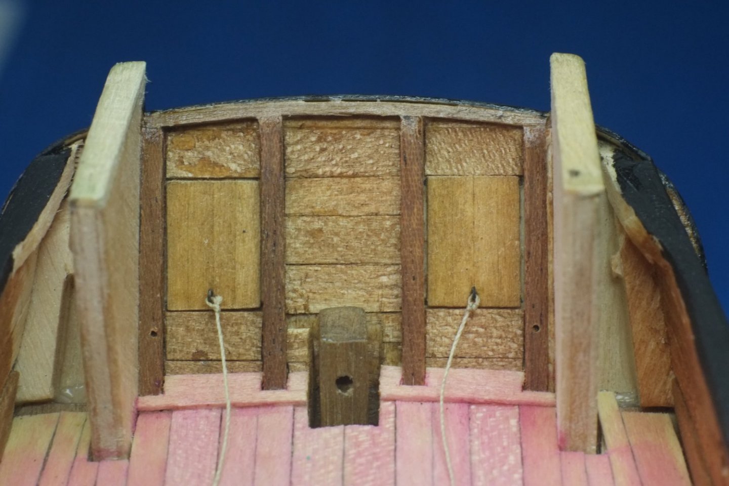
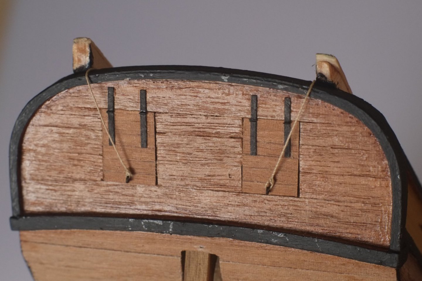
Stern port lids I have now built and fitted the port lids to Whiting. I built them as separate inner and outer layers which I glued to the ply core of the transom. The outer layers have horizontal planks and the inner layers are vertical - my guess for a simple and strong method of construction. I glued in etched brass eyes near the bottom edges, inboard and outboard, and tied some fine thread to them with bowline hitches. That was an exercise in patience and use of tweezers. The hinges are represented by strips of black paper with a short piece of wire at the joint. The holes below and outboard of each lid are for small cleats where the inside ropes will be belayed when the lids are closed The outboard ropes will be tied to the inboard cleats for neatness and so they don't go overboard. (When the ports are open I imagine they would be belayed to the cleats.) George
-
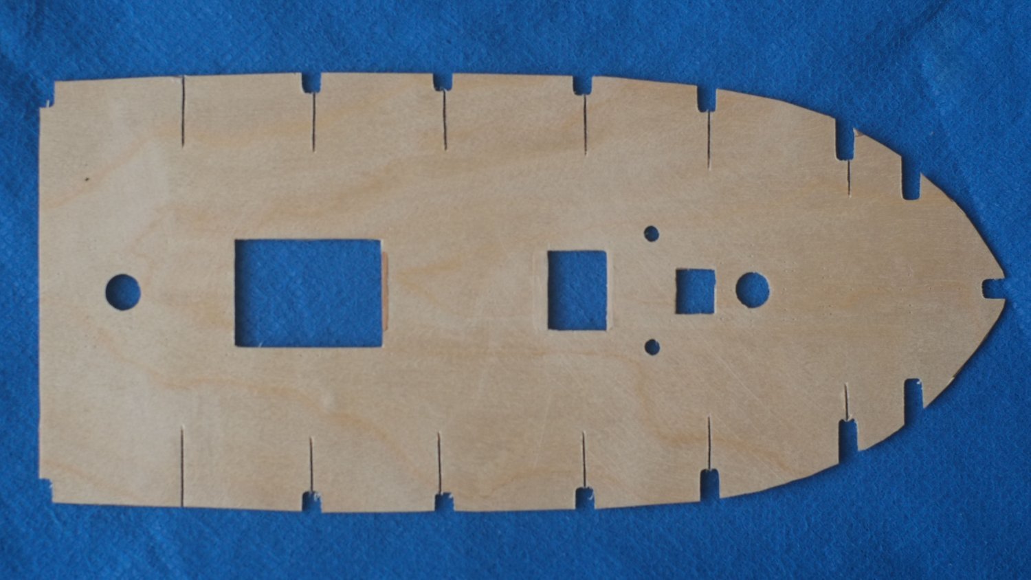
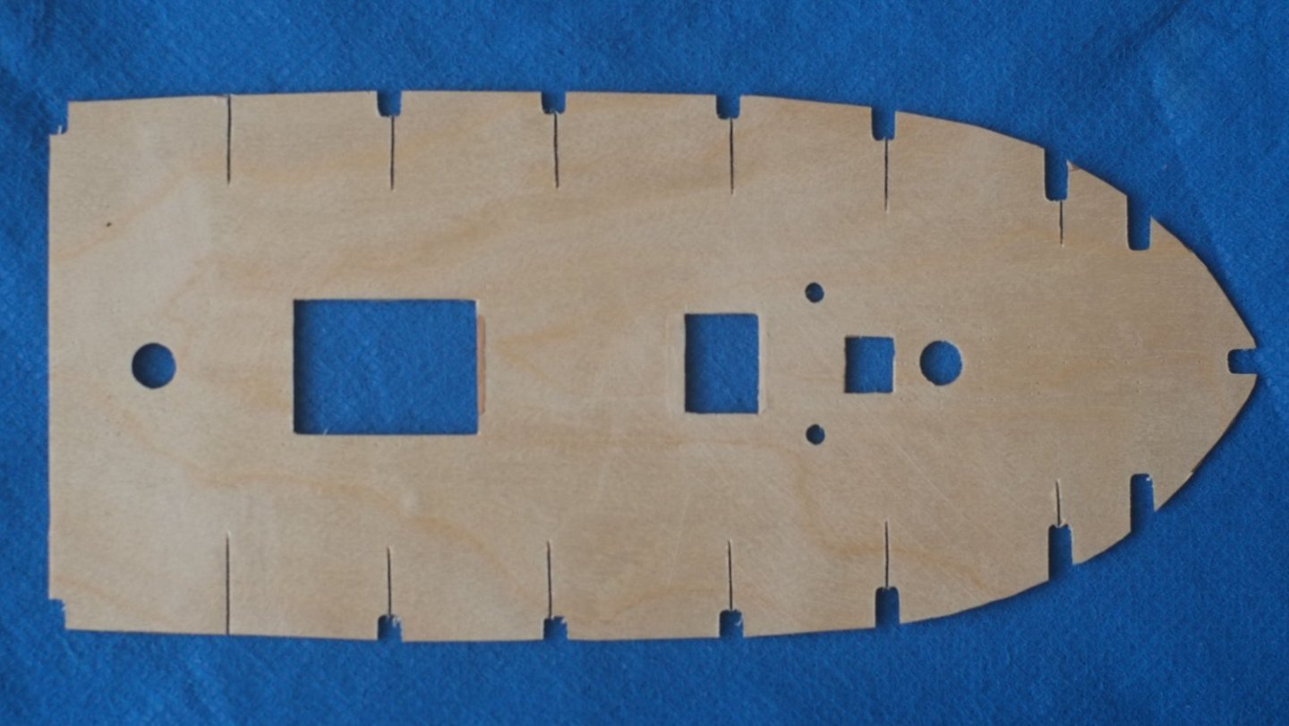
Gregg, You have discovered a common problem in these kits, which is that a flat piece of ply has to follow a compound curve. The only ways to do this are by stretching the ply (good luck with that), putting in cuts (photo below) or ignoring it which is the most common approach. Ignoring it is not so bad here because the fore-aft and side-to-side curves are usually not very pronounced. The deck profiles on the kit bulkheads have too much slope on them and the ply false deck can stand proud of them. Chris's suggestion for extra bits on the bulkheads will work if you are concerned about structural strength and is easy to do. Forward section of the false deck with slots cut in above the bulkheads to allow for compound curves George
- 65 replies
-
- 3
-
-
- Ballahoo
- Caldercraft
- (and 1 more)
-
Gregg, You have made a good start on your Ballahoo. I envy the fit of the bulkheads that you have found in your kit - in mine they were all very loose and would flap about if you breathed on them. I suggest you try the dowel for the masts and check that it fits in the deck holes and spine slots. Hopefully you will be lucky there too and Caldercraft have sorted earlier quality problems. Enjoy your build but be prepared for other design issues such as the carronades which are horrible and oversize anchors! George
-
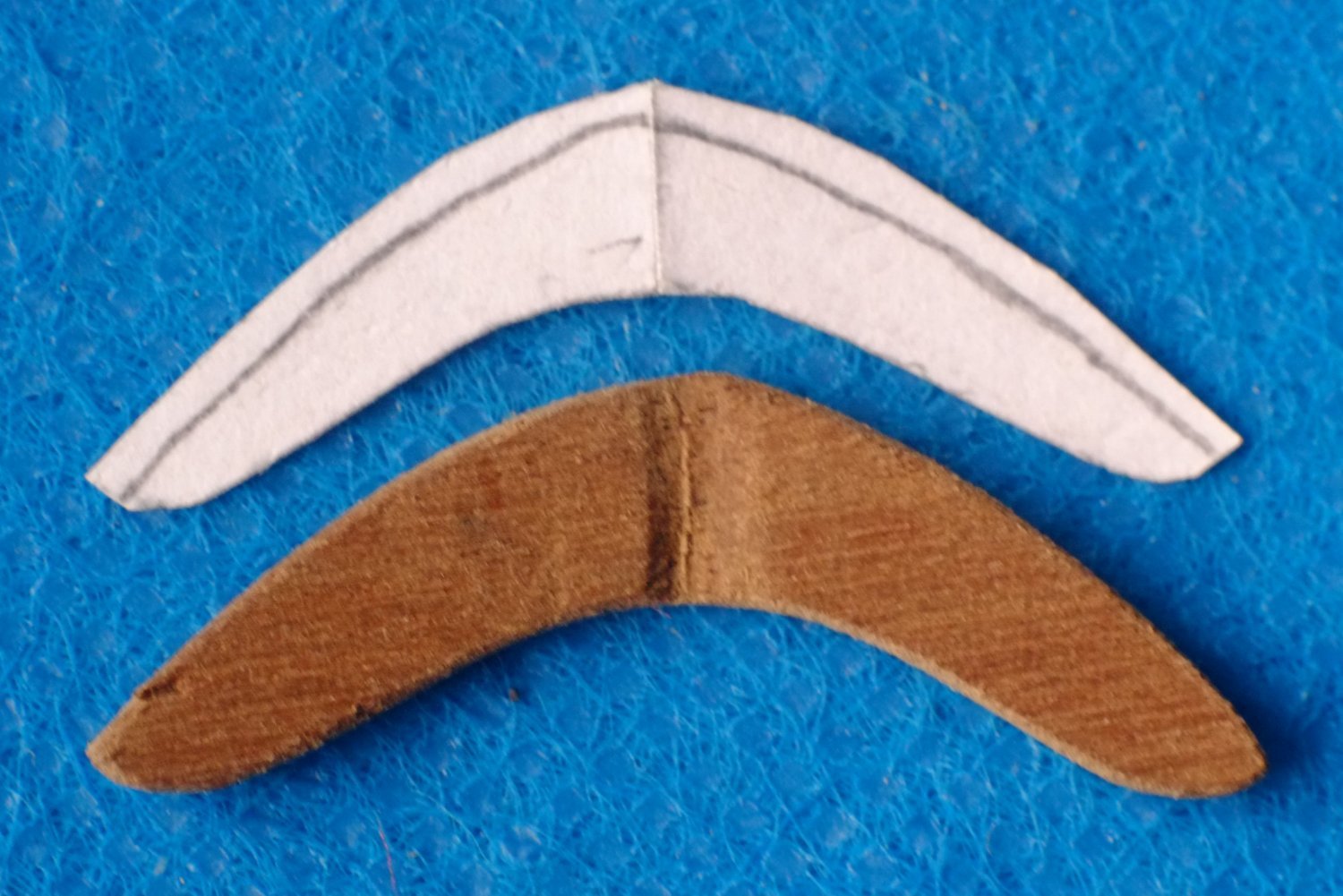
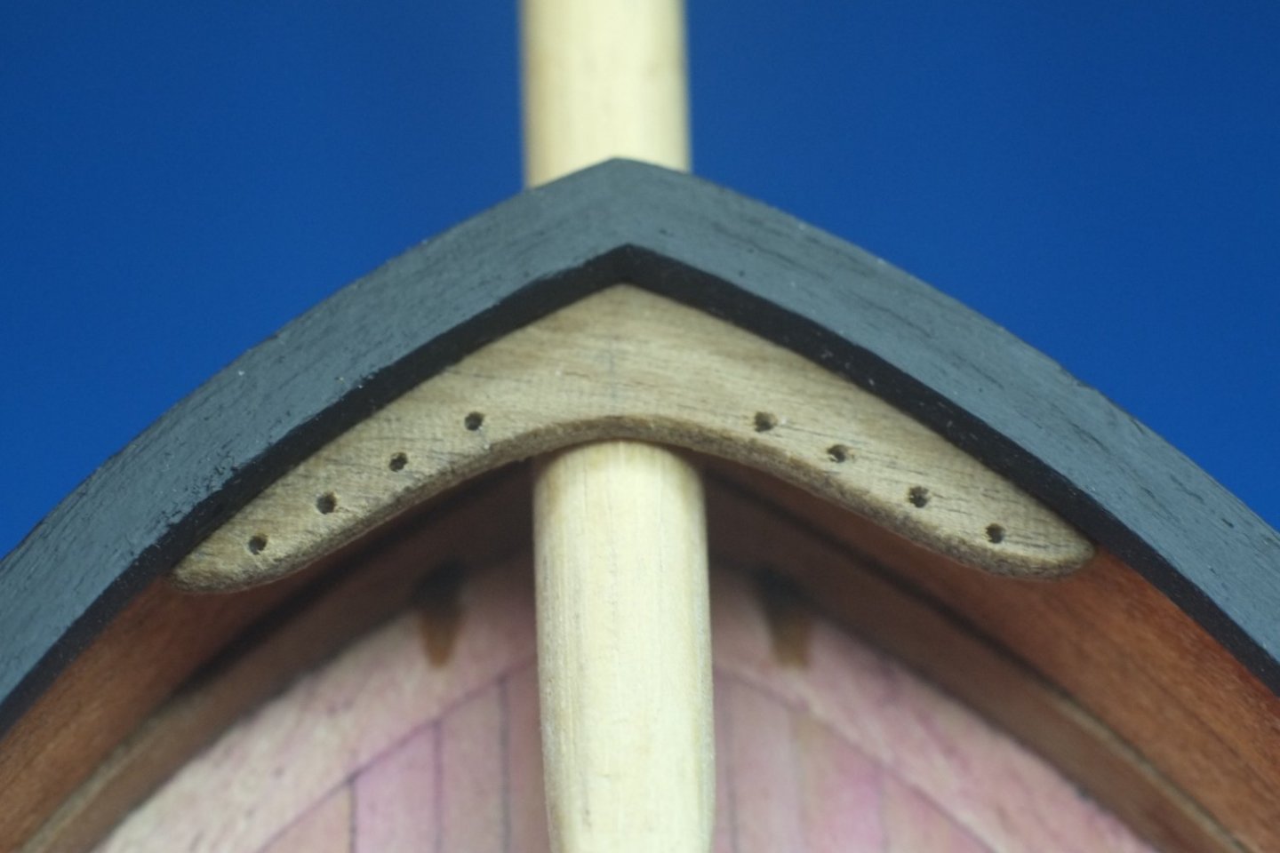
Breast hook I have finished one little job which is to fit a breast hook in the bows. We know it exists because it is mentioned in the letter that accompanies one of the Haddock drawings but I have based its shape and size on what I have seen elsewhere so that is a guess. I also put in holes for belaying pins in anticipation of needing lots later. https://modelshipworld.com/topic/29694-zaz6118-schooner-haddock-drawings/?do=findComment&comment=846466 Construction started with a paper template and I carved the shape from 1.5mm ply. It needed a shallow groove to fit over the bowsprit and the wing tips had to be bent down (after a soak) so they would go under the gunwale. Breast hook under the gunwale and over a temporary bowsprit Stern ports Current job is to make the lids for the stern ports. There is a separate discussion about this https://modelshipworld.com/topic/27728-chase-gun-port-lids/?do=findComment&comment=883753 I am planning on top hinged, outward opening lids though there is not much information about any sorts of lids. George

-
Lieste, Great minds think alike! I had the same idea as you but have not seen evidence for it, and also thought of a problem: if the port lid is open and hanging down loose then it will be vulnerable to waves hitting it. Because of the leverage the force of a wave would be magnified at the hinge, which could be damaged. I have now decided on the top hinged, outward opening design. Internet searches have not shown any more detail about the Science Museum (London) model so there will be some guesswork here. Thank you all for your suggestions. George
-
Alan, Thank you for taking the time to search for a remembered drawing. There must be some interesting history behind those sketches. I have mentally explored a lot of ideas for a stern port lid. Top hinged and opening outwards has similarities to conventional gun ports and this gives it some credibility. In this situation I would have a rope on the outer face that comes over the transom and ties to a cleat 'somewhere' to hold the lid in the open position. When the lid is closed this rope would be tied to the same cleat so that the end is not lost; a sailing friend has described a cleat which has a hole in it to trap the end of such a rope. Something is needed to hold the lid shut since gravity would pull it down. A sliding bolt, or a wood bar through a hoop would do the job, or another rope tied to a cleat. I like the concept of a rope and the lid hanging slightly open because this would let water out, but a following wave would push it shut against a rebate. Thanks for planting that idea above, SpyGlass. (This all reminds me of leading 'brainstorming' sessions at work, in the days when I still worked.) George
-
Jud, SpyGlass, Thanks for your comments about aft chase guns. According to the Admiralty drawings Whiting had ports in her stern but I cannot see how they could fit guns into the tight space around them, let alone serve them. She only carried four guns (two 6lb cannon and two 12lb carronades) and moving one of them into the stern would itself have been a difficult operation with a step up and a step down in the deck on the way. I doubt if the Fish (Ballahou) class were expected to carry stern chase guns but I have no evidence for this. It seems likely but I still have to decide what to do about the port lids. As for running away upwind, that is a good plan if your little schooner is being chased by a square rigger. Whiting was not so lucky and was captured twice in 1812, by schooners, though the first capture (by an American privateer Dash) was more by subterfuge than skill at sailing. George
-
I am reviving this thread because the time is fast approaching for me to decide on the stern ports for Whiting. My thoughts are that Whiting would have ports that can be closed because of the risks from a following sea: waves could easily enter through stern ports and the water would then be trapped in a short section of deck that runs from the transom to a step up where the deck is over the captain's cabin. I also think it looks better for my model. So much for my justifications. Peter Goodwin's Alert book has photos of a cutter model 'around 1785' that was displayed in the Science Museum, London. The photos show port lids that are hinged at the top and open outwards, much like the ports on the sides of the cutter. This is the style I plan to use on Whiting. Unfortunately, the resolution of the photos is poor and I cannot discern any details. Even more unfortunately the Science Museum closed its ship models display some ten years ago and there is no reasonable chance of seeing this cutter. My plea for help! Does anyone have photos of this model which show the stern ports? Or a similar model where there are hinged port lids? Otherwise I have to resort to engineering judgment and guesswork and that is a route which is harder to defend. George
-
Mike, Just right for the period you mention is 'Two years before the mast' by Robert Dana, first published in 1840. This pops up quickly in a web search and you can get pdf or paper versions. The pdf that I have does not react to a word search so you would have to read the whole thing to find a boat hook (if there is one), but a more recent scan might behave better. The book is worth reading anyway to get a flavour of serving on an American merchant ship and sailing round the Horn to what became San Francisco. George
-
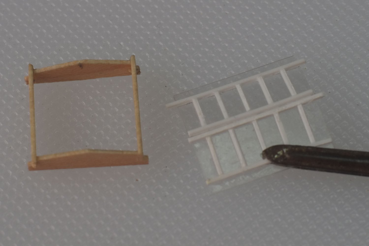
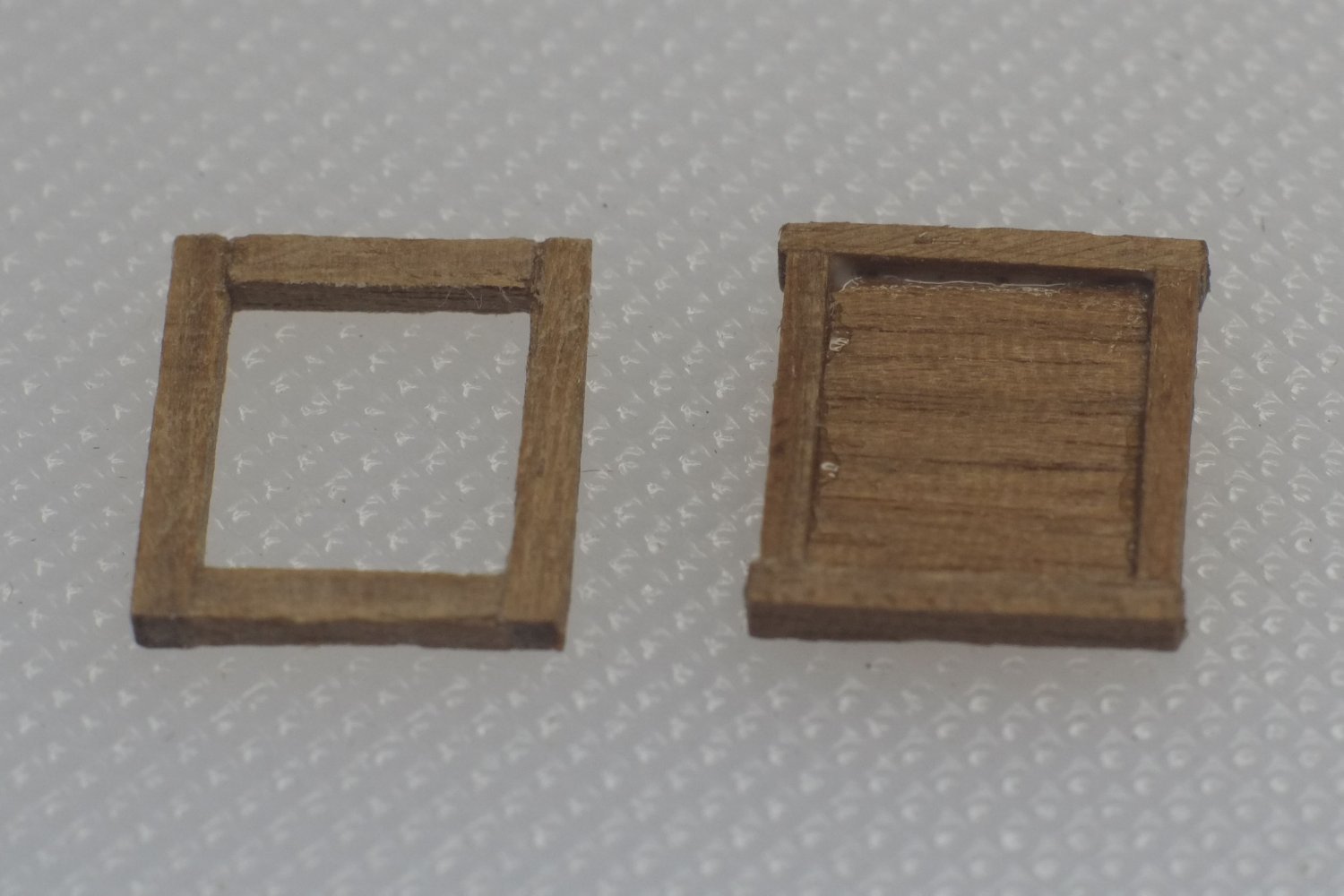
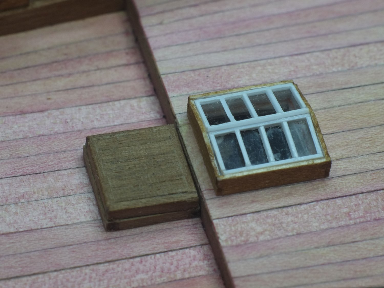
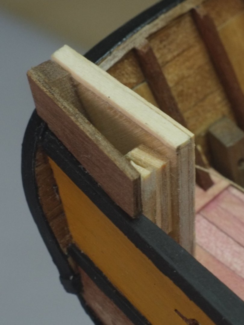
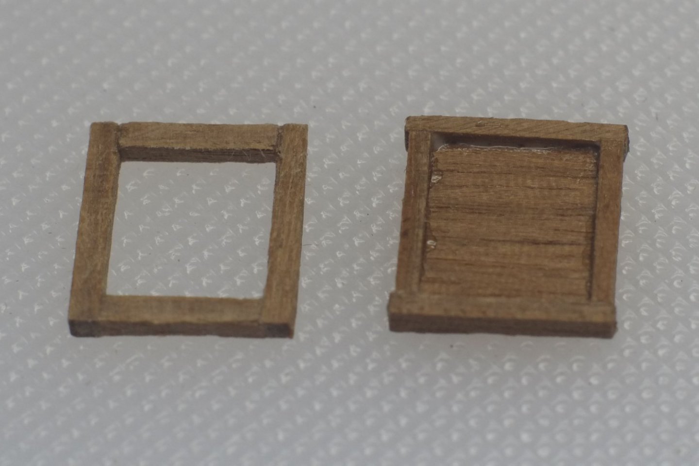
Here is a view inside the housing over the main ladder way to see the bucket and rags. Skylight The skylight (called companion on the Haddock drawing) starts with a coaming that has a sloping top. I made it from 0.5mm planks because the thickness is visible. The light at the top is from a piece of acetate on which I had scored lines to show where the framing bars would go. These are from plastic strip, 20thou (0.5mm) square section that I glued on with CA. Components for the skylight Scuttle to bread room I guessed that this would be a box hatch which has a solid lid over the opening; a grating would let in water and that is not good for the ship's biscuits. I made it from offcuts of walnut in two main parts. One is a lower coaming frame, the other is the lid that sits on it. I made the lid very slightly smaller to accentuate the join between the two. Components for the scuttle to bread room Final picture today shows the skylight and scuttle in position. George


-
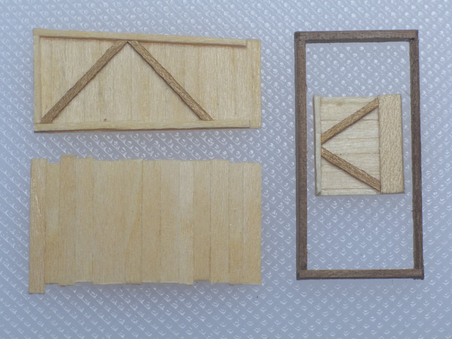
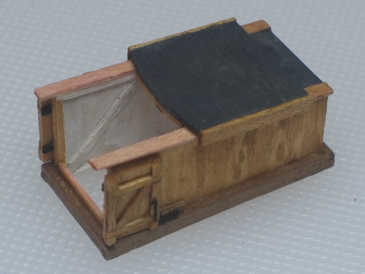
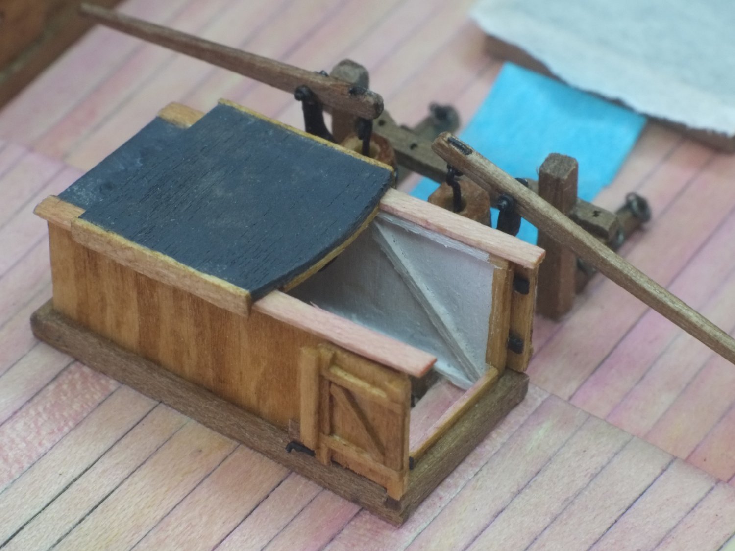
Housing over main ladder way I want to anticipate questions or comments about the name of this structure which is now often called a companionway cover. Falconer's dictionary describes a companion as 'a sort of wooden porch placed over the entrance or stair-case of the master's cabin in a merchant-ship'. The Admiralty drawing for Haddock describes the skylight in the deck above the commander's cabin as the companion. So there is little agreement about the name for this glorified shed that kept the water out of the main ladder way. As mentioned in the previous post I designed my own shed and used experience from designing and building a band stand at home, together with pictures and current practice. What comes out from this little project should look reasonable and be justifiable but it does not link to a contemporary record and is mostly from my imagination. The design I chose has hinged doors at one end (starboard), a sliding roof section and a fixed roof. The roof panels pretend to be covered in canvas and tarred. The sides and doors are from vertical planks on a timber frame, and I have made guesses about bolts and hinges and handles, and rebates and overlaps to keep out the water. The photo below shows the main components. The vertical planks are about 2x0,5mm and are split down from deck planks in the kit. I edge-glued them together and then added the frames. The doors were made in the same way but with more elaborate framing. The roof panels were from 1.5mm ply which came from the frets in the kit. Main components for the shed - two sides, back end and coaming After assembly I painted the inside white. Most of the outside is stained a walnut colour except for the rails that support the sliding roof. I assumed that these would be worn fresh and gave them a pink stain. The sill in the doorway is also pink from wear. The roof panels were painted grey and I deliberately made it blotchy to simulate worn, tarred canvas. The hinges for the doors are black paper and the bolts are odd bits of etched brass. The shed with doors and roof glued open The ladder was trimmed to shape and glued into the hatch. Because of sloping floors and sides and different 'verticals' it sits at a small angle. The shed then goes over it and I allowed enough deck inside the door for a sailor's foot before he starts to descend on the ladder. At the back of the shed there is a small covered area of deck and I put a bucket in there and will probably add a bundle of cloth, ready to mop up the water when it gets in. Shed installed on deck It's only a little shed but I don't think it would have taken me much longer to build a full size one. George