DONATION DRIVE - SUPPORT MSW - DO YOUR PART TO KEEP THIS GREAT FORUM GOING!
×


georgeband
-
Posts
304 -
Joined
-
Last visited
Content Type
Profiles
Forums
Gallery
Events
Everything posted by georgeband
-
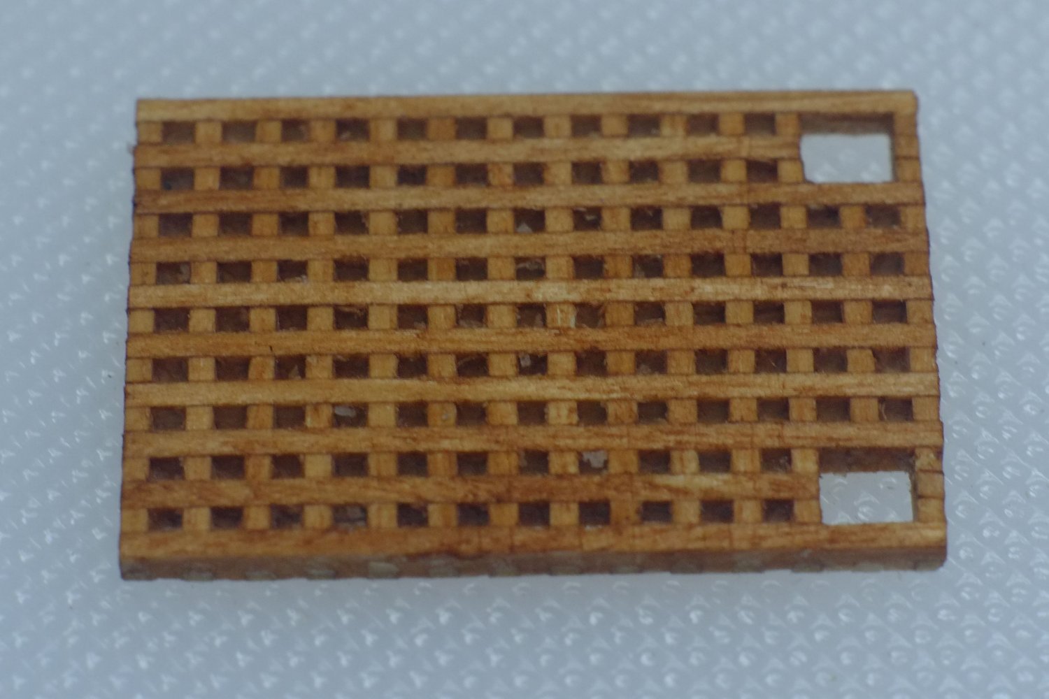
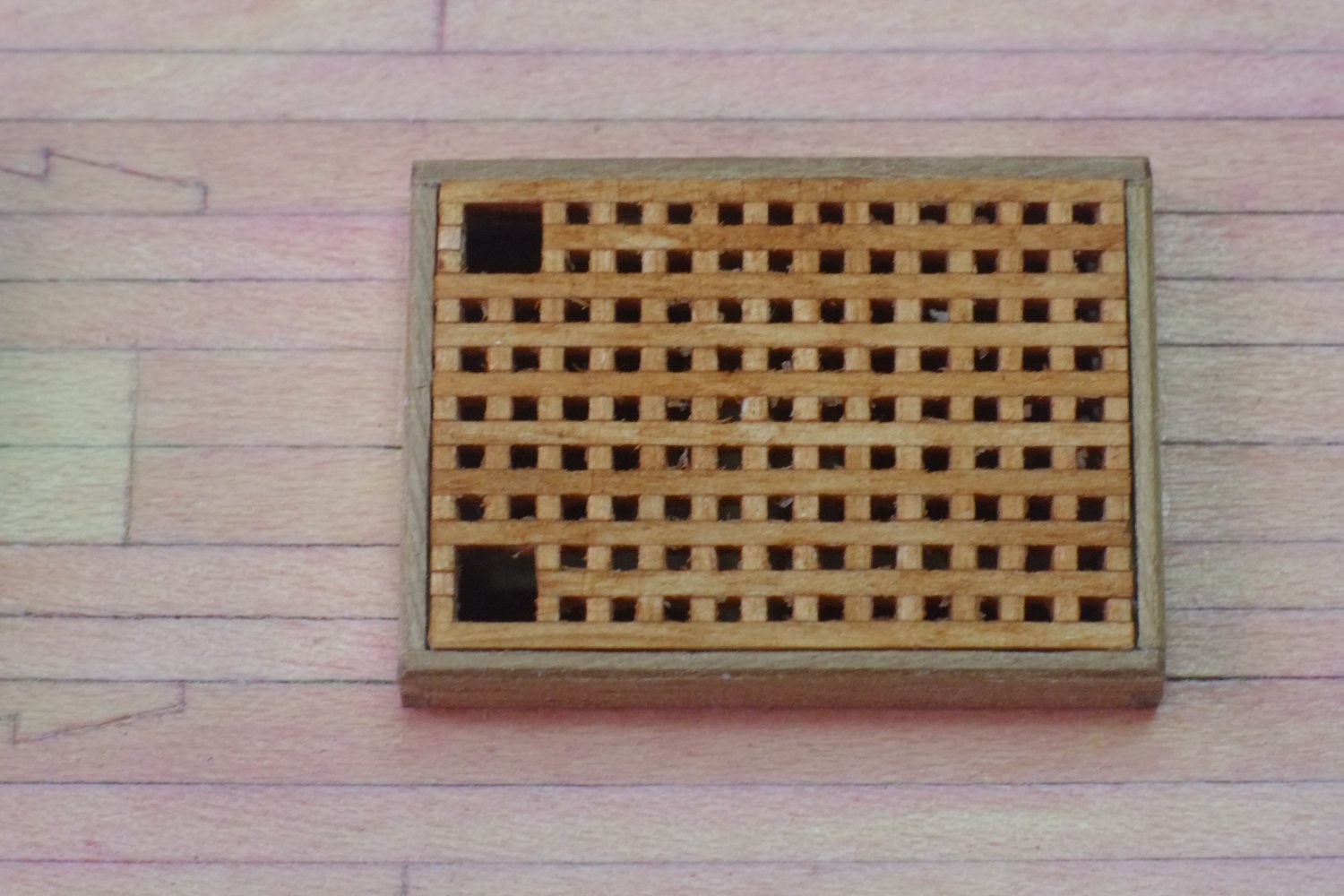
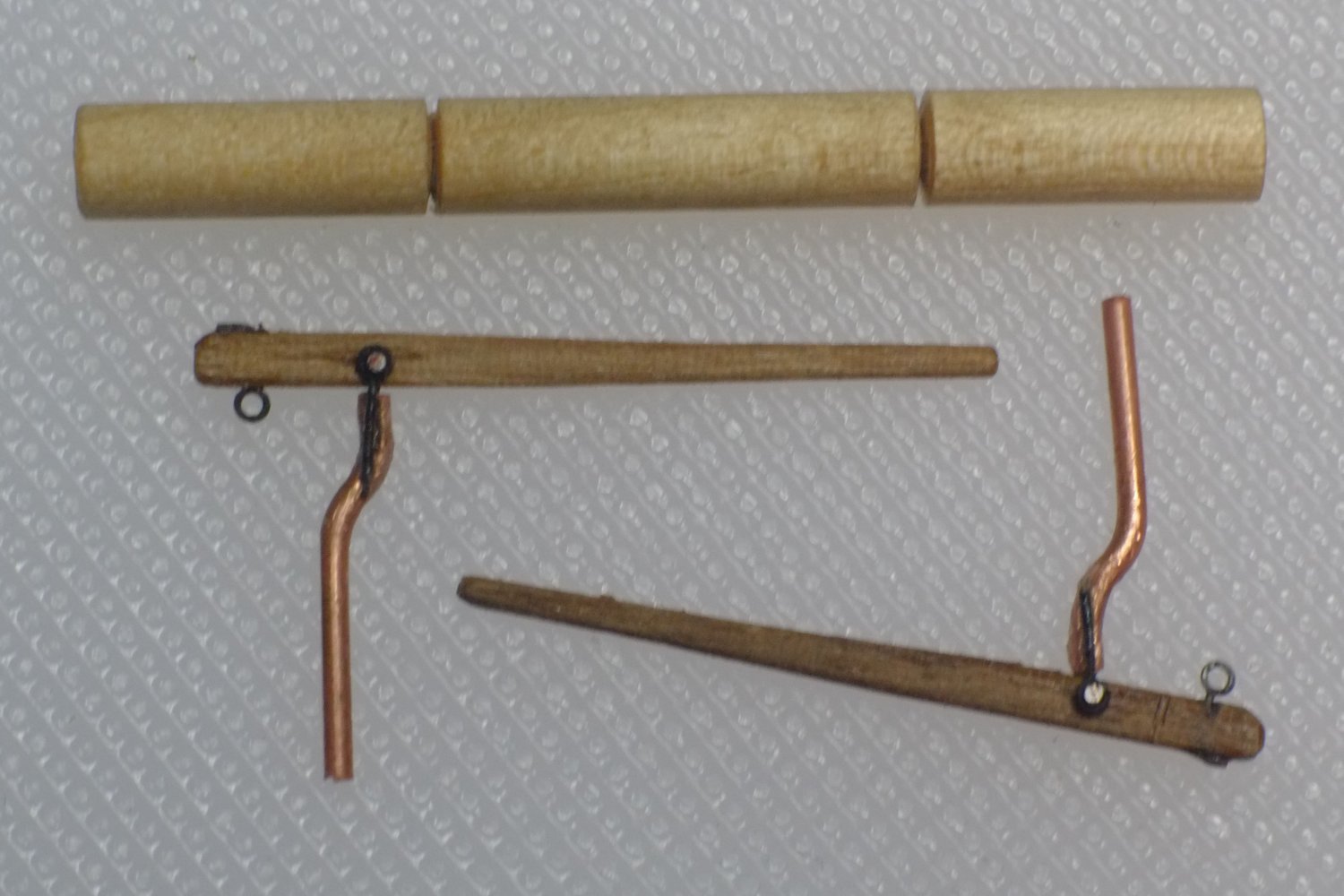
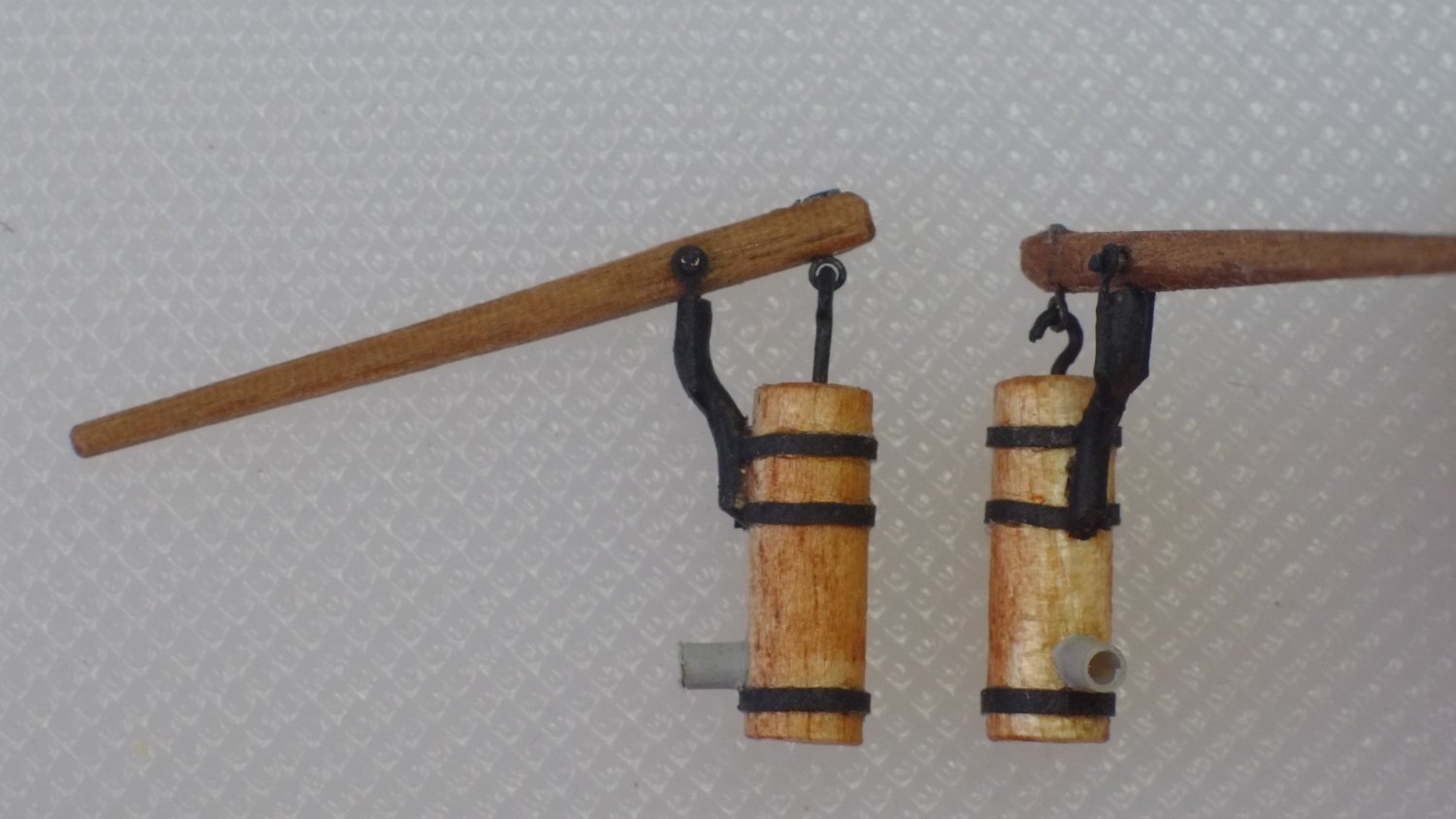
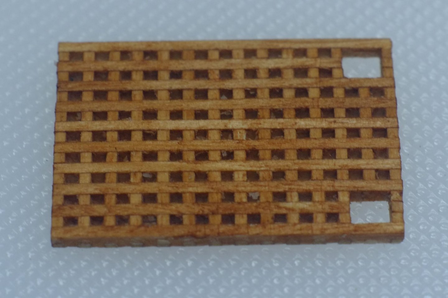
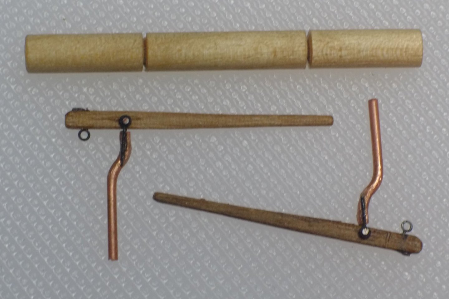
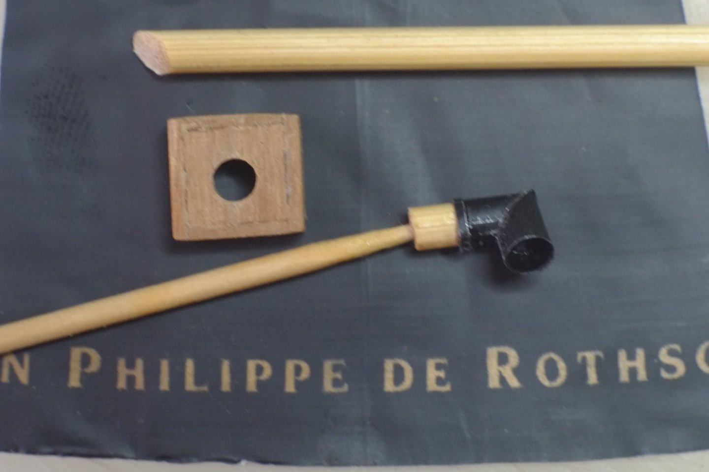
 More deck furniture Main hatch and grating The main hatch has a grating over it and I used the 'combs' supplied in the kit. It is better to have extra length of comb beyond the size you want if, like me, you tend to round the edges when sanding. I left two open squares at one end for anchor cables to go down to the hold. (The kit shows navel pipes for the anchor cables but they are unlikely in this period.) After the glue had set I sanded down the thickness from both sides, the reason being that I want the interior lighting to be visible through the grating. Grating sanded down to 1mm thick. The combs are over-long at this stage When the thickness was correct I trimmed off the sticking-out bits of the combs, opened up the holes for the anchor ropes, and filled in a few slots in the combs that were left open because of the anchor holes. I gave the assembly a light brushing of wood stain (water based dye) to hide the bright white wood. Grating complete The coaming was built to fit the grating; I wanted the edges of the grating to be complete lengths and not a 'comb' which can happen if you start with the coaming. I used 1x4mm walnut and made simple overlap joints. A little sanding ensures that it sits flat on the deck with no gaps. I glued a ledge inside the coaming (1x0.5mm wood strip) to support the grating so it sits just proud of the coaming. I glued the coaming to the deck but left the grating loose for now in case I need to have access to the insides later. Grating and coaming on deck. I have spent what seems like hours cleaning out the holes in the grating but there is always some detritus in them. At some point I will have to say 'enough'. Pumps The drawings that I have found of pumps all follow the same basic concept but differ somewhat in the detail. The pumps in the kit and those available as after market components looked clumsy to me so I chose to scratch build a pair to my own design which looks plausible though I cannot point to a reference to justify it. They are fiddly because there are small parts to make and assemble but nothing too difficult. The body of the pumps is from 4mm dowel and 12mm long. The Haddock drawings suggest an octagonal section but I chose to keep mine round. I drilled a 1.5mm diameter hole at the top end. The handle is 28mm long (6 feet in scale) and I cut mine from 1mm thick walnut. The height/depth of the handle is 2mm at the pump end and 1mm at the sailors' hands. Other parts are copper wire, etched brass eyes, black paper, plastic tube. Pump components. Dowels and wires are over length to make handling easier Pumps finished and ready The pumps went into the box of finished parts and will be installed later. George
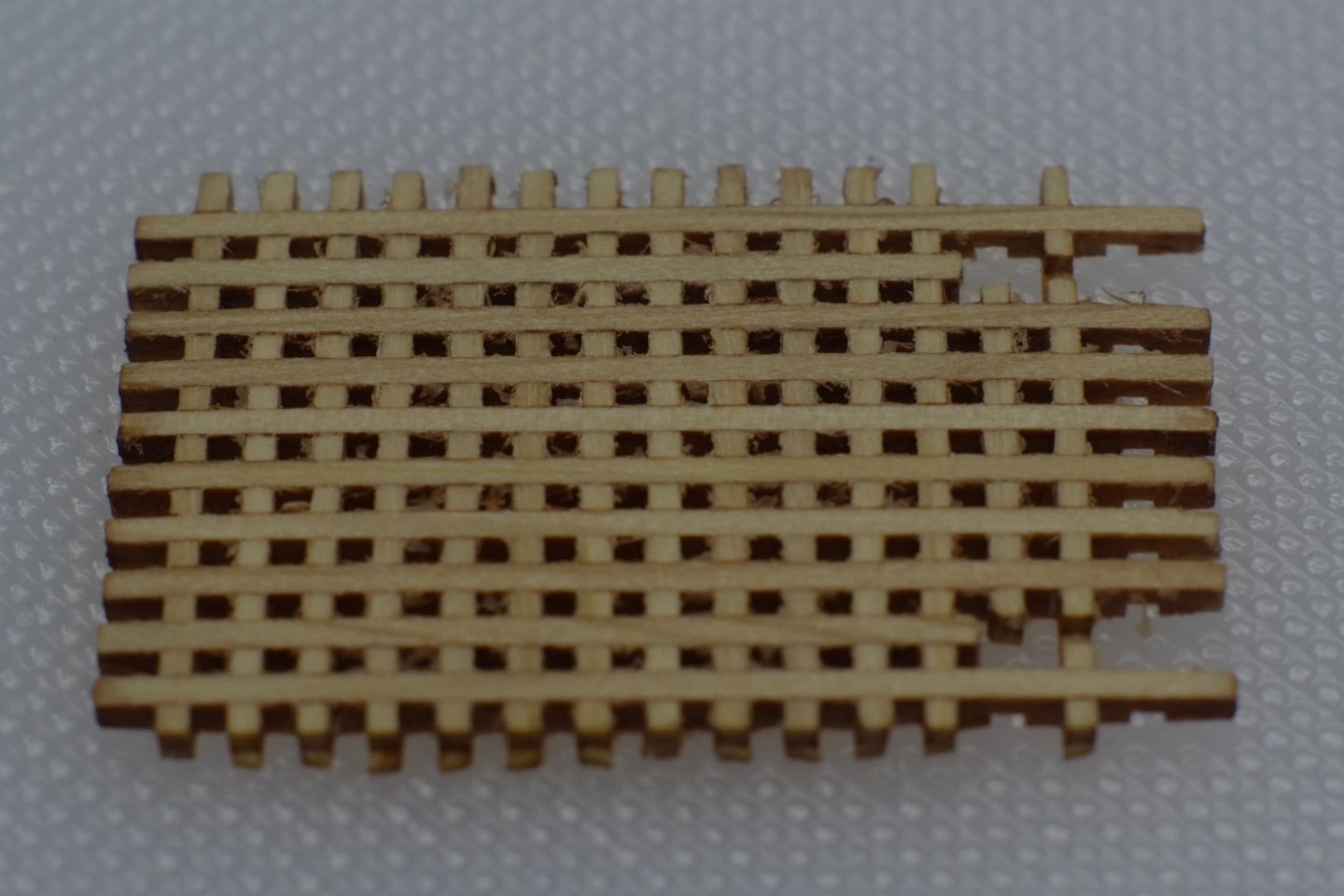


-
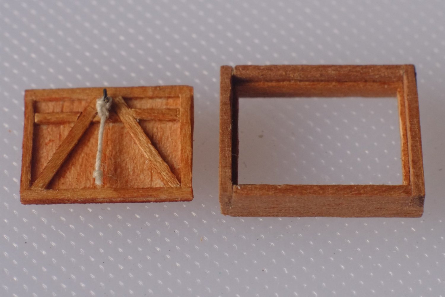
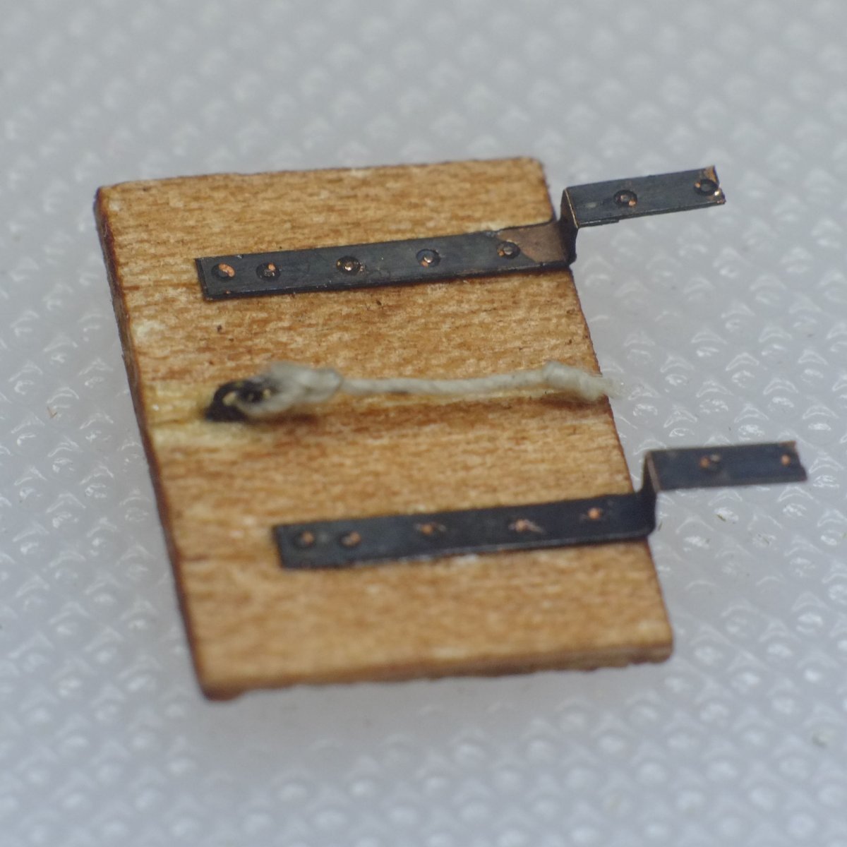
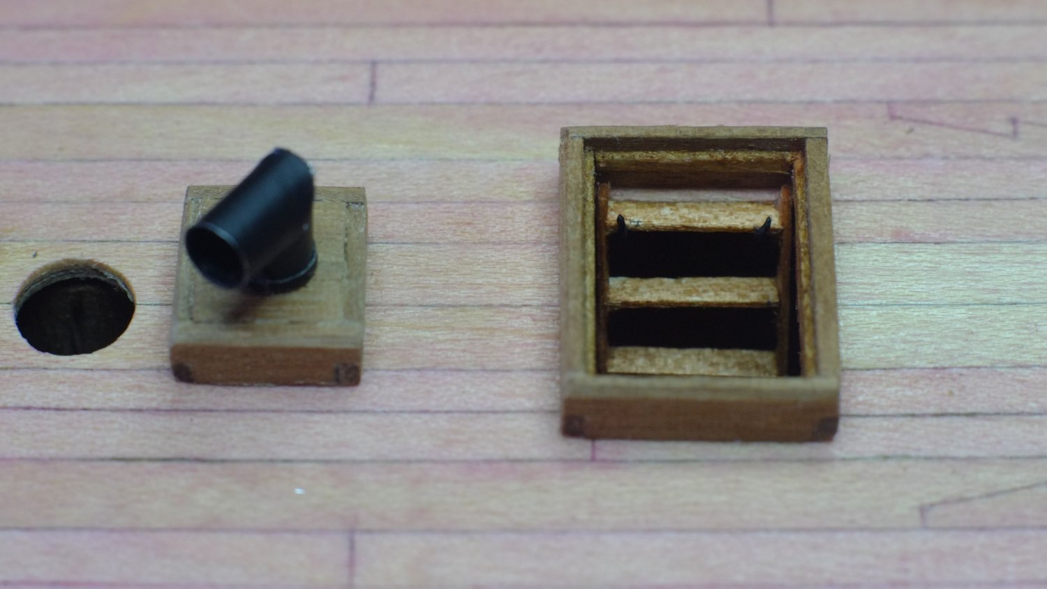
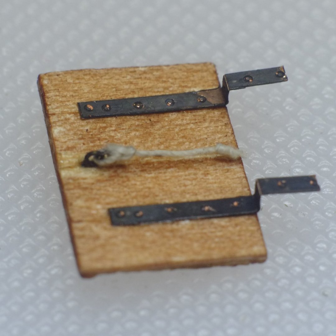
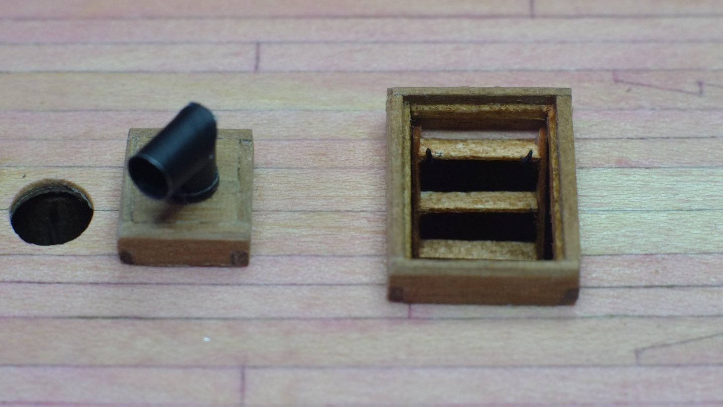
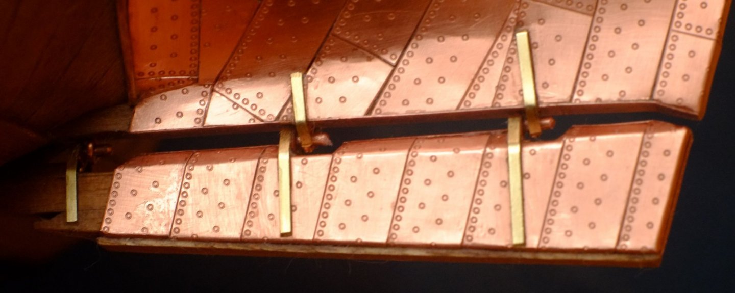
More deck furniture Working my way aft and avoiding the breast hook, the chimney came next. The housing is a simple box with a hole in the middle and the chimney itself looks like an open topped pipe on the Admiralty drawing, but I chose to give it an extra cowl to keep the rain out. I made the chimney from black aluminium foil (mine came from a very nice bottle of bubbly) with a bamboo barbeque stick in the middle as a former. It was a bit fiddly but I like the end result with black and exposed metal; the inside of the cowl needed a smudge of black paint to hide the aluminium. Work in progress on the chimney (other bottles of wine or bubbly also have black foil) Chimney fitted aft of the fore mast The fore ladderway came next. I had made the ladder previously from 2x0.5mm deck planking and stained it. The coaming is from 1x4mm walnut with overlap joints and has a ridge on the inside to support the hatch cover. The cover was made from strips of 0.5x4mm deck planking glued edge to edge, and then I fitted a frame to the under side. The shape of the frame was from imagination and a bit of practice making doors and gates. The mock hinges that hold the hatch cover to the aft end of the coaming are cut from copper plates and were chemically blackened. I added a rope on each side of the cover, tied to an eye with a bowline hitch and with a stopper knot at the end. The cover will be attached later when it will not be so vulnerable to getting knocked. Coaming and inside of the cover for the fore ladder way Upper face of the hatch cover with mock hinges Ladderway and coaming set aft of the chimney. There are a couple of mock hooks under the top step of the ladder to stop it sliding and falling... The hatch cover is safely stowed for now. George


-
The 12ft cutter I ordered on Friday arrived today (Tuesday) and is a beautifully crafted, delicate model. Like Glenn (glbarlow) says above it takes away the need to make a difficult extra on a larger model and I was bracing myself to scratch build a clinker hull out of thin card. I will still have to make the insides and the oars but that is a minor issue compared to the hull. Well done Chris for providing these extras. George
-
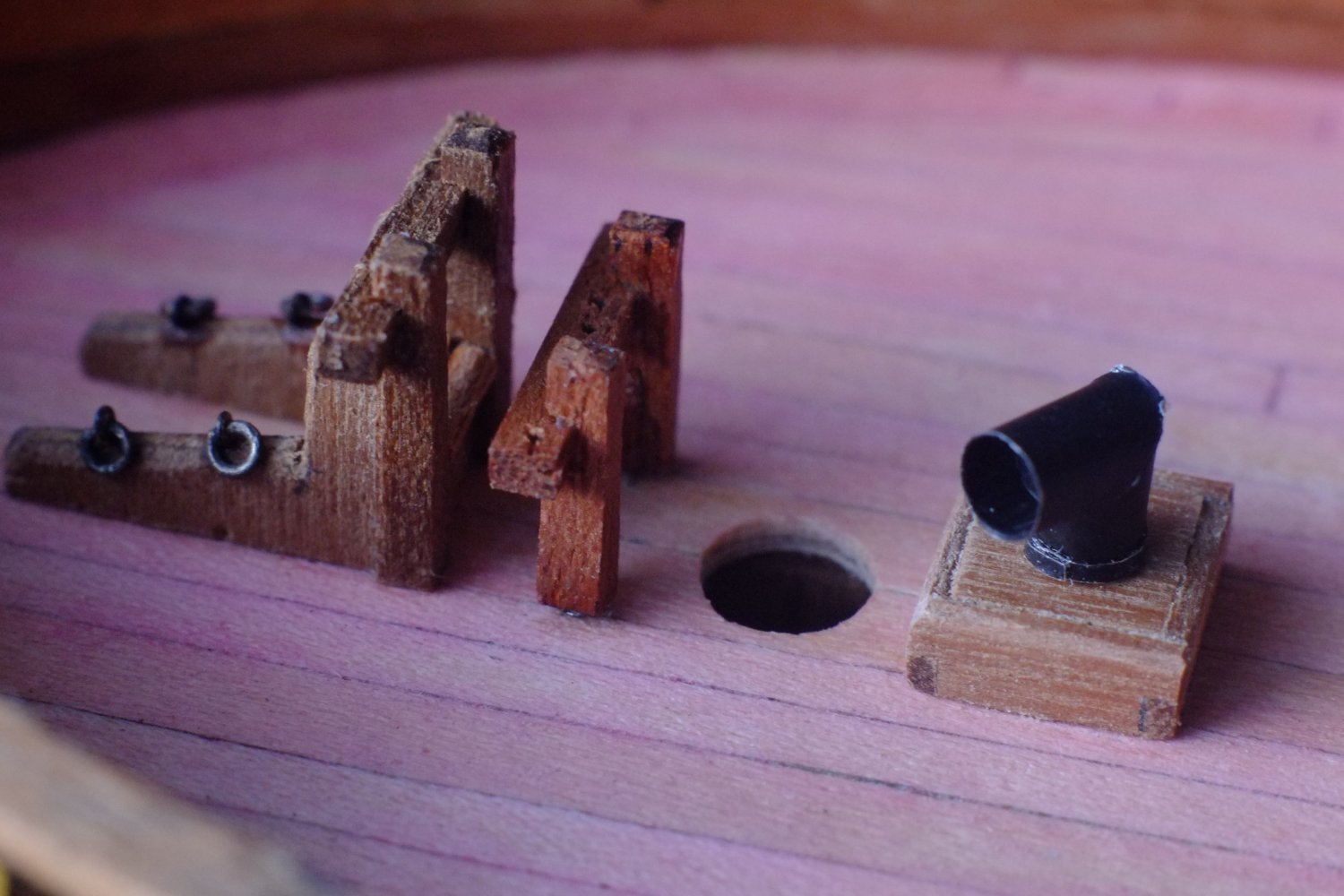
I have done a little more coppering, which was to fit brass rings over the support stands. These are plumbing olives which glue over the brass tubes easily. The ones by the keel, where the stand enters the hull, are purely decorative. Two that are lower down the brass tube sit on the wooden base and set the height of the hull and make sure the waterline is horizontal. I can now return to carving and improvising and making the fittings on the deck. First off was the bed for the bowsprit heel, which also has rings for the anchor bitts, and a fife rail. Both of these sit forward of the fore mast. The Haddock drawings provide a clear plan view but the side profile is lost among the other lines. The Cuckoo drawings are better for the side view. The pink colour is deliberate and is a close match to Bermudan cedar The fixed eyes are etched brass (Caldercraft) and the rings are from copper wire, all blackened with Carr's solution. I have started on a breasthook which looks somewhat like a boomerang. Work on it has paused while I try to work out how many holes for belaying pins I need to put in it; I will probably drill as many as will sensibly fit. More to come on this and a chimney. George

-
This is an impressive level of service! Thank you, Chris, for responding so quickly and positively. I will be ordering tomorrow. George
-
Chris, These little cutters look superb and I would use one on my HMS Whiting (Ballahou or Fish class schooner) apart from one tiny detail - they are too big! According to a log book I have read the boat was hoisted on board and the only space available to stow it is too small for even a 14 foot boat. Could you make a scaled down version as a 12 foot cutter? Please? It should not be too difficult with 3D printing... George
-
Ten years after writing Super detailing the cutter Sherbourne I see things in it which I would now do a little differently and some which would require a lot more time. It remains a guide for a beginner who wants to add more detail to a starter kit and it avoids major surgery and expenditure on new components. I have no plans to create a second edition because, despite retiring from real work, I simply do not have the time. I have had a few emails recently which ask if the book is still available and the short answer is yes. I have copies at home and can post them to you. The sales through Model Dockyard have stopped, now that Nick Tonkin has retired, but he passed on his remaining stock to Cornwall Model Boats. They are now down to zero, but if you prefer to buy from them then apply a little pressure and they should restock from me. Happy new year - 2022 George
- 10 replies
-
- 7
-

-
- Sherbourne
- Jotika
- (and 5 more)
-
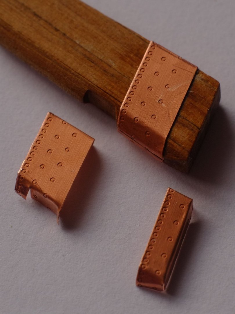
Gregory, The Amati plates are 18.2mm long and 6.2mm wide (I leave it to you to convert these dimensions into inches...). I bought one pack and have 80 whole plates and a lot of trimmings left over. Allan, The debate about copper plates and nail patterns is similar to those about sails and ropes and wood grain. It is very difficult to get to a true scale size on a 1/64 model and the best we can achieve is to get something that looks right to our eyes. The complication is that my interpretation of 'right' will not be the same as what others think and it is hard to set an absolute standard. Let's take an example of the nail indentations in the main body of a plate. These are too small to be seen individually on many photographs but their regular patterns are picked up by our eyes which are good at that task. Your Connie photo above is a case in point and I can readily identify rows where individual nails are lost in the noise. I expect to see something on a model that reminds me of the nail pattern (personal preference, others hold different views) but the existing technology struggles to achieve that. Caldercraft's soup bowls are excessive, a plain copper sheet misses the point, and Amati are somewhere in between. Yes, the Amati marks are too big at scale but I would rather have something than nothing and at this point in life I do not want to start designing and making my own etched plates with smaller dots. Amati have made a compromise that suits me, and I do like the way their plates have blank edges to simulate overlaps. It does not suit everyone and I respect your opinions. A factual note, returning to the original theme of this thread. Vanguard Models make etched copper plates in 1/64 and have nail marks similar to those on Amati. Unfortunately, the dense nail pattern at the edges is on all the edges so it is not possible to butt them against each other to simulate overlapping. You have to either overlap them physically, which leaves a gross step, or cut off two edges from each plate which makes them too small and is tedious. That is why I chose Amati instead of Vanguard. (Btw flogging a dead donkey is an alternative to beating a dead horse. I find both acceptable as metaphors but would not indulge in them in real life.) Best wishes, George
-
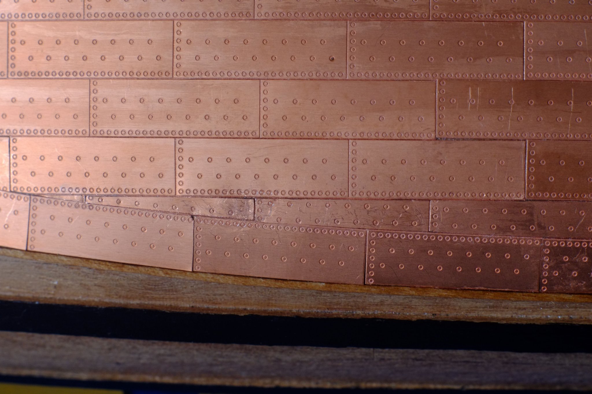
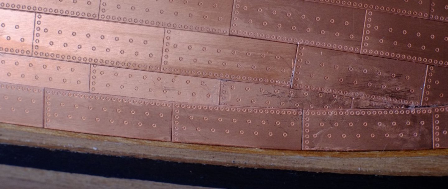
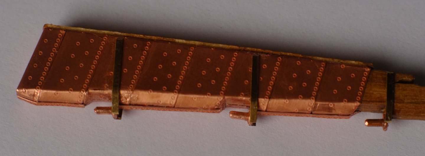
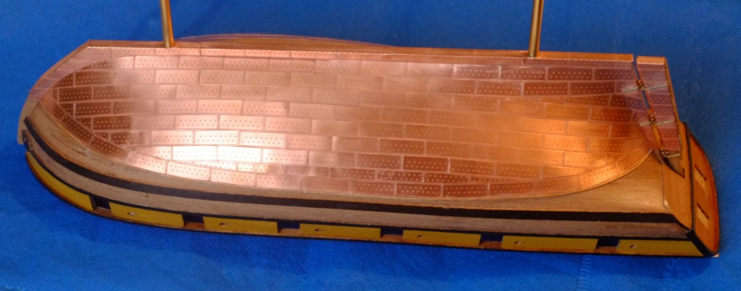
I have recently completed coppering Whiting in 1/64 using the etched plates from Amati. These plates have a full nail pattern along two edges, one long and one short, and the other edges are blank. A few more nails adorn the middle of the plates. I trimmed back the blank edges to achieve close fits against the adjoining 'nailed' edges: this simulates the overlap and removes any problems of over-thick plates. (True thickness was about 0.8mm.) The plates come in port and starboard flavours. The hull is upside down here and shows the plates just below the waterline When the plating was finished I rubbed down the surface with grade 0000 steel wool and applied Renaissance Wax to protect it from the sweat on my fingers. At normal viewing distances the nail patterns are quite subtle and show that there was something there. Full details are on my build log. George
-
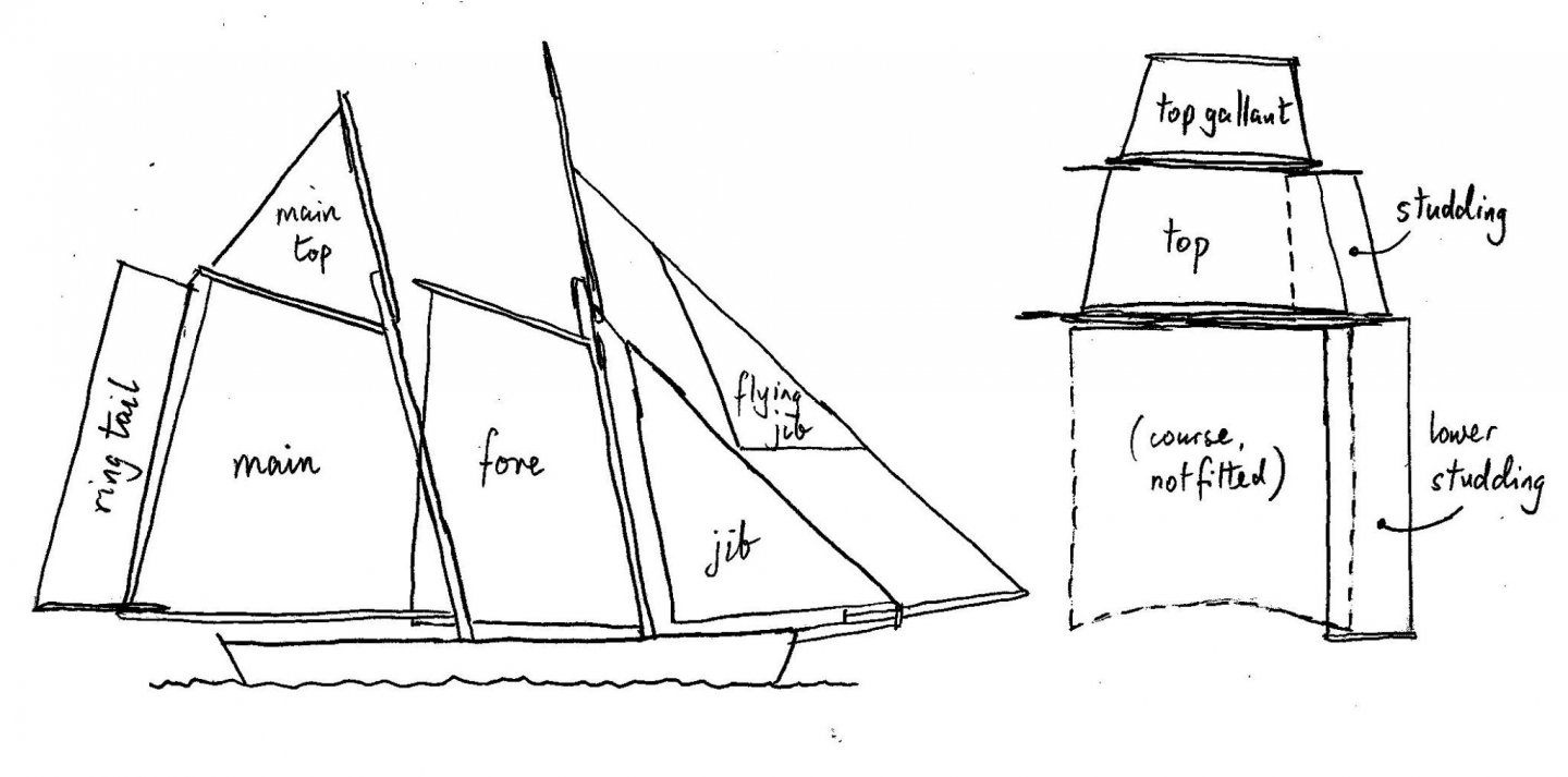
sail plan for Ballahoo (Fish class) topsail schooner
georgeband replied to georgeband's topic in Masting, rigging and sails
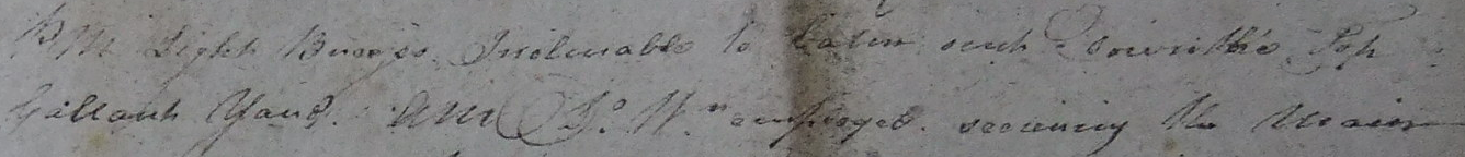
Thanks Wefalck and Phil for your further comments. My sketch of a sail plan was to indicate the names of the sails and I apologise if I caused confusion by drawing the flying jib sail so high. From my observations and your comments it is much more likely that this sail was just above the jib boom. I would guess that the tack was tied to a traveller on the jib boom while the halyard went up somewhere, probably to the top of the lower section of the fore mast so that it did not depend on the top mast being fitted. But I can be convinced either way. The picture below is of a model in the NMM Greenwich collection, Flora, dated 1825. This link should take you there but I have attached one of the three pictures. https://www.rmg.co.uk/collections/objects/rmgc-object-66109 This is how I imagine Whiting was rigged, pretty much, though there will be some differences. On Flora the fore top gallant is fully rigged. I am reconsidering whether the fore top gallant was set flying on Whiting. The log book by John Roach has one entry which states 'PM Light Breezes Inclinable to Calm sent Down the Top Gallant Yard...' This contrasts with others such as 'at 7 all Sail Set Strong Breezes Took in the Gaff top Sail Flying jib sail top Galt Sail'. Perhaps I am reading too much into the words and he was describing the same thing, or it could be that the top gallant could be 'taken in' as well as being 'sent down'. If the meanings are the same then the top gallant was set flying, if they are different then it was rigged. I think I need to visit The National Archives again and photograph some more log books. George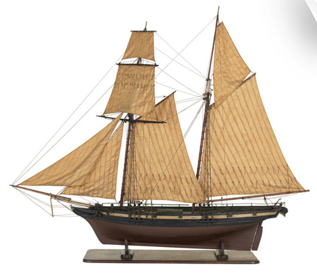

- 22 replies
-
- 1
-
-
- caldercraft
- jotika
- (and 4 more)
-
sail plan for Ballahoo (Fish class) topsail schooner
georgeband replied to georgeband's topic in Masting, rigging and sails
Phil, Thanks for your analysis of the position of the fore stay which sounds quite logical and reasonable. It is backed up by John Roach's use of the phrase 'jib sail' which points to a forward location on the jib. People have reminded me occasionally that 'the clue is in the words'. I find that Marquardt's Global Schooner does not have quite enough information about the bowsprit and jib boom and I turn to another favourite of mine, Petrejus' Irene. Petrejus is thorough with his sources and writes extensively around a subject. His focus is the Cruizer class brig but so much transfers to a schooner. I have looked in Steel and found an entry for sloop's water sail on page 127. SLOOP'S WATER-SAIL. This sail is quadrilateral, cut square on the head, and made of canvas No. 7. It is occasionally spread under the boom of the main-sail in fair winds. The leeches are either cut square, or have one gored cloth. The depth of this sail is from one-half to three-fourths of the length of the boom, and it is 4 or 5 cloths wide. The bolt-rope, on the head, foot, and leeches, should be one inch and a half in circumference. *** When sloops have lower-studding-sails, they are similar to the water-sail: the leeches are square, and they are one yard deeper than the leech of the cross-jack, or square sail. Steel's words are quite clear about the location of the water sail and it being called a lower studding sail on a sloop. What is less clear is the illustration in plate 24 which suggests that the water sail is taller than it is wide - the head rope and foot rope are labelled on the drawing. The best interpretation that I can make is that 'head' and 'foot' refer to features of the sail as it is made and not as it is used. I suspect that Marquardt came to the same conclusion (or found another source) because his drawing on page 185 shows the water sail lying sideways with the cloths horizontal. I am still a student and thoroughly enjoy researching a topic to understand 'why'. Fortunately I have now retired from full time work and can devote more time to pursuing my studies. Best wishes for the New Year George- 22 replies
-
- 1
-
-
- caldercraft
- jotika
- (and 4 more)
-
sail plan for Ballahoo (Fish class) topsail schooner
georgeband replied to georgeband's topic in Masting, rigging and sails
I have picked up on a comment in Marquardt Global Schooner, page 186, where he discusses studding sails. He says that the water sail which hangs below the boom at the stern can be regarded as the 'lower studding sail'. The ring tail sail above it is the matching upper studding sail. This can explain the entries in John Roach's log about a lower studding sail and the absence of anything about a square sail on the fore mast. The sail plan should have the lower (fore) studding sails removed and a water sail added. George
- 22 replies
-
- 1
-
-
- caldercraft
- jotika
- (and 4 more)
-
Rob, Your photos of Glory of the Seas are not visible at the moment. Some mistake with downloading? George
-
sail plan for Ballahoo (Fish class) topsail schooner
georgeband replied to georgeband's topic in Masting, rigging and sails
Phil, Thank you for your extensive comments which save me a lot of typing! I also hold Marquardt's Global Schooner in high regard and am sure that we have recommended this book to each other several times. I like that Marquardt quotes his sources though many of them are secondary and not primary. Books from 1800 are not necessarily correct (as with the Naval Chronicle for John Roach) and if the errors are repeated many times over the years they come to be regarded as fact and not an author's interpretation. Similarly, Marquardt's modern drawing of a Fish schooner has differences from the Haddock and Cuckoo drawings at Greenwich which I have studied extensively, and which makes me question the fine detail he includes in other illustrations. It is a great book, but apply some caution if you choose to follow it. Marquardt presents a lot of options in extensive detail but leaves open many decisions about which variety of rig was carried on any particular schooner outside his list of examples. The information from a log book for Whiting is historical evidence of the highest calibre and provides clear answers to some questions (eg top gallant sail was carried) but still leaves others open. One of these is about the fore sail / jib sail which was carried, but we do not know if the stay itself was tied to the stem post or the end of the bowsprit. This is where judgment comes into play and I rely on opinions from people like you to guide me. The decision in the end is mine and the mistake is mine if I get it wrong though in many cases the matter will remain unproven and we have a balance of probabilities. The next stage of modelling Whiting for me is to build the furniture on the hull. This includes pin rails around the masts and inside the chains and for them I want to know how many belaying pins are needed. To get that I have to know the rigging plan, which comes from the sail plan and the mast arrangements, which is why I am looking at this now. Building the masts and yards and sails is probably a year away at my build rate. More opinions please! George- 22 replies
-
- 2
-
-
- caldercraft
- jotika
- (and 4 more)
-
Sail plans for schooners are poorly documented with little information about the varied combinations of sails that they carried. I am building HMS Whiting (Ballahoo or Fish class) and in the absence of any useful drawings have taken to reading log books. There is one by sub-Lieutenant John Roach that I photographed at The National Archives in Kew, London and have now partly transcribed. (Wikipedia calls him George Roach and gets it wrong. They refer to Rif Winfield and I think the original mistake is from the Naval Chronicle in 1806 which erroneously put George on Whiting. The log book clearly states John Roach.) There are lots of mentions of sails and sailing in Roach's log and I have noted which ones are present or missing. He also mentions some of the spars such as the jib boom which answer other questions. The sketch below is a summary of what I found. The drawing itself is based on one by Phil (Dr PR) and the proportions are not quite right for Whiting. https://modelshipworld.com/topic/25679-topsail-schooner-sail-plans-and-rigging/ Fore and aft sails, starting from the bow Flying jib. Several mentions. Jib. Comments such as 'took in the jib boom set the reefed jib' show that there was at least one row of reef points. There is no mention of a fore stay sail. There is one mention of a bonnet on the jib, Fore sail. This was used a lot and could be double reefed. Main sail. Like the fore sail this could also be close reefed. It was replaced by a try sail in bad weather. Main top sail. Several mentions. Ring tail sail. Several mentions. Square sails, starting from the deck There is no mention of a course or lower square sail in all the time from April to October. However, there is a curious reference to a 'lower' studding sail which might be alongside the (missing) course. Fore top sail. This was reefed and the mention of a 'first reef' suggests that there were probably two rows of reef points. Lots of mentions of studding sails (starboard and lee are two variations) which I presume are next to the top sail. Fore top gallant. This went up and down several times so was probably set flying. The log book does not give the mast arrangements. The main mast would have had a lower and a top section and I am fairly confident about that. The fore mast could be made from two or three sticks and Roach does not solve that problem for me. The top mast and top gallant mast could be one long pole, or they could be in two separate sections. At present I tend towards a combined top and top gallant mast, largely because the top gallant sail was (probably) set flying and would be relatively small. Later and larger schooners as shown in Peterssen had separate sticks. I might have to visit Kew again and photograph some more log books to get more snippets of information. I will include detailed interpretations in my build log for Whiting, but welcome comments on this post too. George
- 22 replies
-
- 4
-
-
- caldercraft
- jotika
- (and 4 more)
-
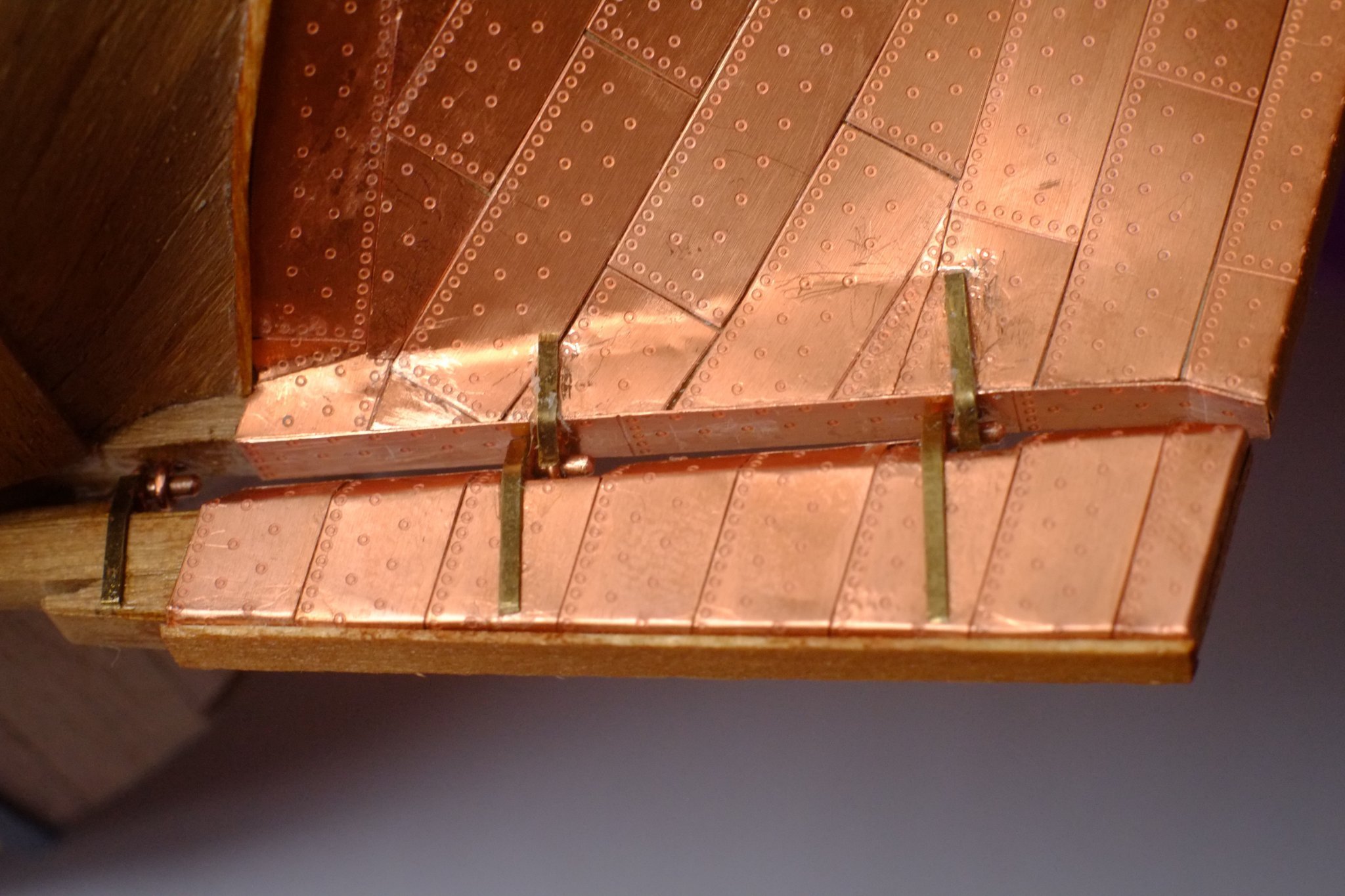
Copper plating finished It feels good to have finished this stage of the build. Most of the individual plates had to be trimmed to fit and it is more difficult and slower with copper than with wood. The rudder was a pleasant change and I built it from 4mm thick walnut because the kit part was wrong. The wood came from the frets around some of the kit parts. I used copper wire eyes from the kit for gudgeons and pintles; for the pintles a short piece of thick copper wire was glued into the eye. Plating was slow around the pintles because of the complicated shapes. Rudder build up from 4mm thick pieces of walnut Start the copper plating Rudder with pintles, brass straps, wood fish plate on aft face After constructing the rudder I rubbed down all the copper (and brass) on the hull and rudder with grade 0000 wire wool (thank you Wefalck for the tip) which revealed CA glue that had dried onto the surface. The glue I removed with a fibreglass brush which is a bit more abrasive than grade 0000 and also easier to aim at problem areas. When the glue had gone I applied the wire wool again and the same shiny surface returned. The final rubbing down was lengthwise along the hull so that there would not be different surface effects from the angle of the micro-scratches. To preserve the finish I applied Renaissance wax (thank you Vaddoc) using a variation on the technique shown in the original Karate Kid movie: Apply the wax with a cloth, leave to dry for a short while, buff the wax to a shiny polish. I have now put on three coats and might yet add more. George

-
I have compared the surfaces cleaned with grade 0000 wire wool with those from a fibreglass brush. With naked eye I cannot see the scratches but the fibreglass surface has a duller appearance. The good news is that applying wire wool after the fibreglass brush returns the surface to the same lustre. This might be because the finer cut from the wire wool removes the deeper scratches from the fibreglass, or because the wire wool burnishes the copper and 'squeezes' the scratches, or a combination of both. This gives me the option to use the wire wool first, find where there is CA glue dried on the surface, cut back the CA with the fibreglass brush and then blend it all together with the wire wool. The Renaissance wax goes on easily and I have applied three coats. I might yet apply some more if I feel pessimistic. Two photos below are before cleaning and after waxing George

-
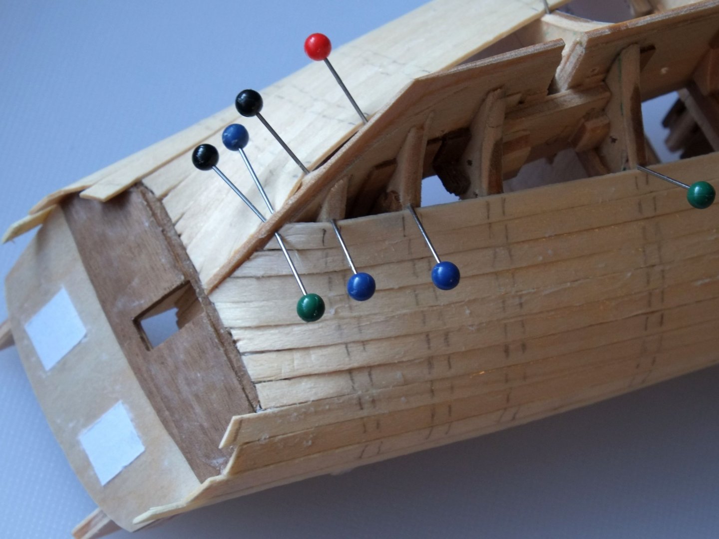
I agree entirely with Allan that pre-bending the planks removes the problem in most cases. When you don't have enough fingers for a fidgety plank and want to hold it down while the glue sets then the techniques mentioned all have their place in the tool box. My preference with pins is to push them in at an angle by the side of the plank so that the pin holds the plank down onto the frame/bulkhead and against the adjoining plank. When you take the pins away there is often no mark left behind, or a small dent that can recover with a little wetness. The photo shows the first planking and the pins are next to the planks. The pairs of pencil lines are guides that I draw on after the planks have been fitted so that I know where to push the pins for the second planking, otherwise there is a risk that you make an unintended hole. In some cases I use pins and clamps and rubber bands, depending on the direction and strength of the force that is needed. Just try a dry fit and if the plank still needs a push somewhere you can improve the pre-bending and twisting or devise a way to hold it down. George
-
A can of Renaissance wax was delivered today and the instructions say that the wax is easily removed with white spirit, so a mistake can be rectified without too much trouble. (Or no worse than removing a varnish; I did that recently for a whole hardwood floor.) I also now have some grade 0000 wire wool and will set up some experiments to look at scratching (wire wool vs. fibreglass brush) and resistance to salty air which we have in our garden (weather dependent). The experiments will be on copper pipe and not the copper plates I have fitted to Whiting and I will present the results when I have them. Thanks all for your advice. George
-
Thanks for your suggestion, Wefalck. Zapon is new to me and a quick Google search suggests that there are few suppliers. I will try the Renaissance wax first and see how easily that goes on. I have a second question on the same theme: how to prepare the copper plates before varnishing or waxing? My thoughts are to degrease with meths applied with cotton buds or a cloth, and use a fibreglass brush to remove residues from the cyanoacrylate glue where it has dried on the surface. Any advice on this aspect? George
-
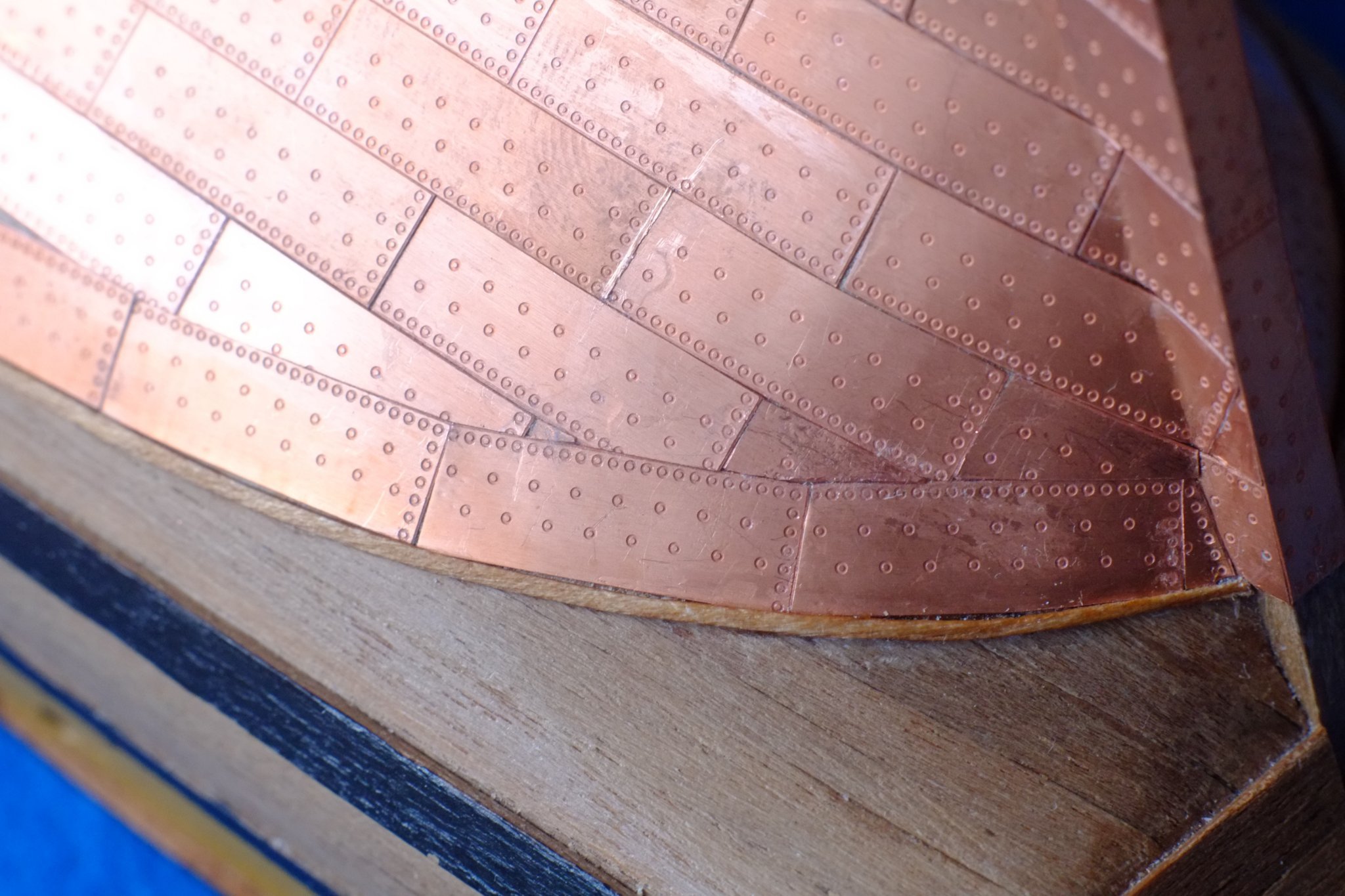
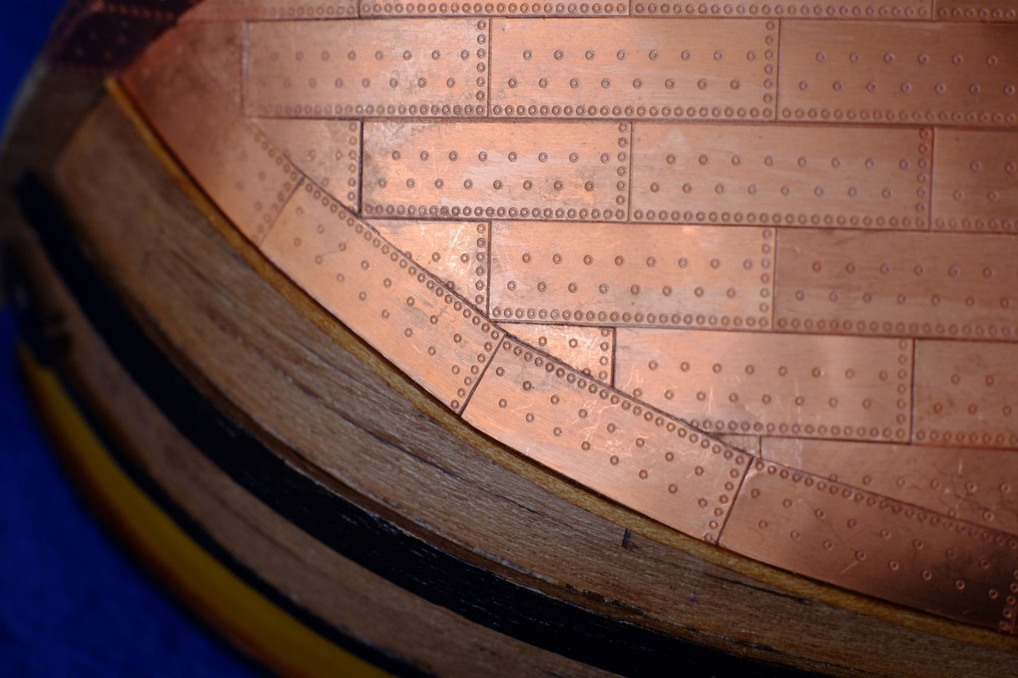
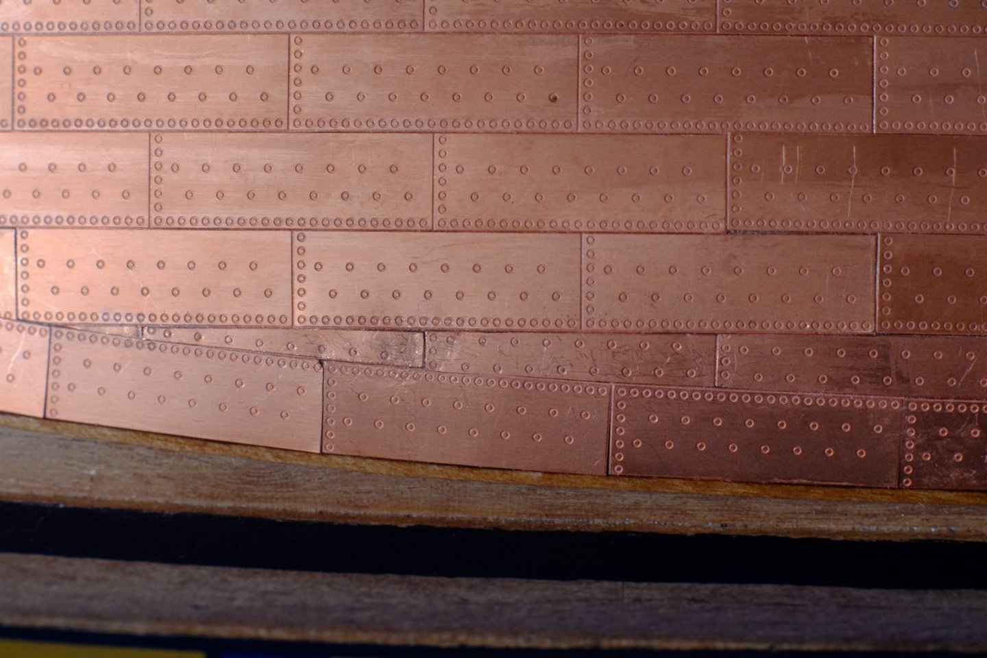
The final copper plates are now fixed to the hull. The infill plates between the main rows and the waterline plates are all individually cut to size and trimmed to fit. I kept telling myself that 'fettling is fun' but it became tedious, and difficult, to hold a small piece of copper and cut all the edges to get a good fit. Some of the plates have five straight edges and those could take an hour each. The tiny triangles had a death wish and leapt into the jaws of the carpet monster, never to be seen again. Waterline and infill plates at the bow Waterline and infill plates at the stern, and a large thumb print which appeared even though I wore cotton gloves Between row 7 and the waterline in the midship area there is space for a narrow row. I cut the plates back on both long edges so that the nail pattern was symmetric: it looks neater to me. Row 8, next to the waterline plates, has narrower plates than the others The hull is finished but there is some more plating to do look forward to: the rudder is waiting to be built first, then coppered. I started a new thread about which varnish to use on copper plates and had an excellent suggestion about 'Renaissance wax' which is used in museums (thank you Vaddoc). https://modelshipworld.com/topic/30576-varnish-coat-for-copper-plates/ Before that the plates will need a thorough clean to remove finger prints and glue residue. My thoughts at the moment are meths (methylated spirit, methanol) with a cotton bud, and a fibreglass brush that I use to clean wire for soldering. Any suggestions? George

-
Thank you all for your comments. I have followed up on the Renaissance wax, Vaddoc, and it is the preferred museum finish for metals, so it should be good enough for a model. I have ordered a tub and will also try it on a replica sea-service pistol that I have. Thanks again, George
-
I am building a 1/64 schooner (HMS Whiting, 1805) and have used the Amati copper plates. Plating is now nearly finished and is described on my build log. I don't want to restart the discussions about what the copper should look like; my personal choice is to start with bright copper and let it slowly tarnish over the years. The Amati plates have a restrained nail pattern which I like. The model will be in a cabinet when she is completed. I want to give the plates a coat of some varnish for two purposes: Protect the copper from my fingers while I continue to work on her. I have worn cotton gloves during the coppering and they do impede the modelling a little, so I prefer to have bare fingers for the upper works. There are a few fingerprints already forming on the copper which I will clean off before varnishing. The varnish should prevent more from appearing. Slow down the tarnishing process. I know that I cannot stop it easily and I have thought about filling the display cabinet with nitrogen (no oxygen) but that is taking things a bit too far. I am prepared to accept the inevitable colour change. I know from experience that copper pipes do not like water based paints (emulsions or gloss) and quickly go green. I have given some copper pipe a coat of matt acrylic varnish to see how it reacts over the next few weeks. I don't have a polyurethane varnish to hand but will probably try that too. Does anyone have words of advice about a suitable varnish? George
-
Tony, You mention a cellotape backing to prevent splitting, which reminds me of some hooked scarf joints I made in 0.5mm thick planks for a waterway. I gave them a paper backing for the same reason and it worked a treat. A possible advantage over sticky tape is that the paper will glue onto your sub-deck substrate. I guess that the thickness of the paper is acceptable? 😉 Some veneers are sold with a paper backing to provide strength during handling, and one supplier I found was quite proud of the quality and thickness of the paper they used. George
-
Tony, I am a little puzzled by the desire for scale thickness of deck planks. If they are grossly over-thick then it might show as the deck surface being too high, too close to the gunwales. If they are slightly too thick then this would only be evident where that thickness is directly visible, and I cannot see where that would occur on Jacinthe. I certainly admire the desire to make as much as possible true to scale, but there are practical limits. I am currently applying copper plates, 0.1mm thick, to a hull in 1/64; the real plates were about 0.8mm thick and I would struggle to achieve this thickness with a coat of paint on the model. However, the edges of the plates are not visible anywhere so who is to know that they are too thick (apart from the model maker and the crowds who read these forum confessions). Best wishes, George