

mij
-
Posts
224 -
Joined
-
Last visited
Reputation Activity
-

 mij reacted to greatgalleons in Niagara by greatgalleons - FINISHED - Model Shipways
fore mast stays
-
mij reacted to Dan Vadas in HMS Vulture 1776 by Dan Vadas - FINISHED - 1:48 scale - 16-gun Swan-class sloop from TFFM plans
Thanks very much Brian, Frank, Janos, Patrick, Grant, Nils, Mark, Pat, Steve, John (welcome back), Spyglass, Dale and Albert .
Good to see you have your Acetone problem sorted Spyglass - thanks for giving him the info Grant, I've been away on one of my extended holidays again .
Roughtree Rail
The final Rail to be fitted is the Roughtree Rail, also called the Quarter Rail. This rail is bolted to the Swivel Gun Mounts on the Quarterdeck, and also has an iron brace near it's fore end.
I made the fore end from a piece of wide stock, cut on the scroll saw. A much easier way than trying to bend it into shape :
Danny
-
mij reacted to Hank in USS NEW JERSEY (BB-62) 67-69 by Hank - FINISHED - Trumpeter - 1:200 - PLASTIC
Since my last post, I was able to contact and correspond with a former Long Beach Naval Shipyard project manager who was involved with the final fitting of radar and electronics aboard USS NEW JERSEY prior to her Sept. 1968 departure for WesPac. Richard Landgraff and I have been erstwhile correspondents/battleship enthusiasts since the 80’s and have now re-established contact after quite a few years of absence. Richard spent well over 30 years at LBNSYD working on the IOWAs through the years as the needs of the Navy changed and the ships were in service and out. Currently he is involved with the USS IOWA Museum located at the L.A. Ports.
After an exchange of photos and a critique of my (2nd) mast assembly, Richard made a few observations which I have amended this week:
1) The foremast on NEW JERSEY was removed in 1967 at Philadelphia NSYD and replaced with a 36” diameter lower pole. The current available plans of NJ of this time period do not show the mast correctly. They also show the mast with a starboard side vertical ladder and this is also incorrect. The ladder is mounted on the front face of the mast; I now have photo proof of this thanks to Richard. I have removed the mast from the conning tower, modified (enlarged) the two mast support brackets and replaced (modified) the lower mast pole to achieve the required diameter ( 3/16” @ 1:200 scale) or as near to it as I could make it without major damage to the rest of the assembly. Historical Note - the original IOWA class foremasts were designed to be lowered in order for the ships to pass under the Brooklyn Bridge in New York harbor. If you compare these photos with the prior photos posted a week or so ago you will see the differences in the mast structure. I've also added the wire rope stabilizing stays on either side of the mast extending to the rear of the ECM equipment houses.
2) The forward tubular bracing I made for the lowest radar platform is not correct and was modified per Richard's directions to more closely resemble the actual bracing. In addition, side tube bracing that was omitted from the after brace was added. These corrections are not all that evident in my photos below.
In addition to the technical knowledge I have learned this week, Richard has also provided me with other snippets of battleship history (namely involving NJ) that probably no one else is aware of. This kind of first-hand lore is slowly but surely disappearing as those associated with battleships and their construction/modification take their final shore leave. I am keeping these items of lore in a separate file as they are related to me in order to hopefully preserve these stories.
One item of interest that I will share is that any photos you see of NEW JERSEY in her late 60's configuration with her 40mm gun tubs up forward of Turret 1 are PRE-deployment photos. Those tubs were removed the day I arrived on board in Sept. 1968 and Richard was supervising the yard crew removing those tubs. We left a couple days later for Westpac.
The photos show the new mast structure with only touch-up painting left to be complete. I will begin work on the 08 Level Conning Station and ULQ-6 antenna arrays next week.
Hopefully, I'll be able to "retain" Richard as my own "Dreadnaught Consultant" on this project since his 1st hand knowledge of this ship is so extensive.
Hank
-
mij reacted to MEDDO in Halifax 1768 by MEDDO - FINISHED - Lauck Street Shipyard - 1/4" scale
I taped off the keel and it seemed to go pretty well.
Until...
I have to be pretty careful going across the frames. It is very easy to fix. No wood damaged just a weak glue joint. A bit of sanding and viola good as new.
-
mij reacted to capnharv2 in Methods for making Treenails
Fantastic work Garward! Thanks for posting the pictures.
Harvey
-
mij reacted to mtaylor in Licorne 1755 by mtaylor - 3/16" scale - French Frigate - from Hahn plans - Version 2.0 - TERMINATED
Let's see if I got this right... first we make lots of little pieces of wood from big pieces, then we make big pieces of wood from the little pieces so we can cut and shape and make little pieces of wood from those big pieces. er.. right? Ok.. I think I got it. I finished making all the bigger pieces of wood from the small pieces. All 60 frame blanks are ready to go.
Now to start cutting the frames from them.
-
mij reacted to NMBROOK in MORDAUNT 1681 by NMBROOK - Euromodel - 1:60 - Beyond Bashed
Thank you very much indeed Patrick,Geoff and Matti for your kind words On to the next,smaller update.I decided to carry on with this side as I still hadn't got my timber.I moved on to the gunports on the next deck.These are different in that many fall in the unplanked,exposed frame area.There is no option but to do them properly.An interesting point is that I am following the information in John Franklin's book as to the gunport sizes taken from the builders model,the main gun deck ones work out at 13mm W x 12mm H,the upper ones are 8mm square!!.I made a simple strip to slot between each side to ensure the cills ran true to the waterline athwartships and cut the rebates out with a burr and scalpel.I also made some simple sanding sticks up to ease the process,notably one wide enough to span between both frames to keep each side level.The excess will be sanded off after the top and bottom cills have been glued in place.
Kind Regards
Nigel
-
mij reacted to NMBROOK in MORDAUNT 1681 by NMBROOK - Euromodel - 1:60 - Beyond Bashed
I have completed the basic 'inner' hull structure to the starboard side.As I am waiting for a timber delivery I thought I may as weel sort out the lower gunport linings.After studying Euromodels drawings and also pics of the builders model,it became apparent there were differences not just in the position of gunports but also the height and shape of the top of the hull sides.Because I want to reflect the design of the NMM model I would have to address these areas.The most notable fact is there is a gunport right forward on the museum model that is missing on Euromodels representation.Looking at the design you would probably only get a musket in there,but it is there nevertheless.Also the stern galleries are very different and you will notice the gunports are close up to this.This basically meant starting from scratch and the bulk of the ports were moved aft slightly.An additional port would then fit in at the beakhead,but also the first and last port on the main gun deck are spaced differently.My revised design reflects this.
There is a three page article in John Franklin's book covering the builder's model which gives the exact gunport sizes and wale scantlings and spacings.The Euromodel kit design shows upper wales that are too small in comparison.In order to get things to work the top edge of the hull has been increased in height to compensate for this.You will notice the additional pear laminations on the top edge,the bulkheads are too short to run to the top.The lower of the pear strips has been 'dowelled' with 0.7mm copper wire into every pear upright.This has resulted in an incredibly strong hull wall even before planking.
Kind Regards
Nigel
-
 mij got a reaction from Bindy in HM Yacht Chatham by JohnW - Caldercraft - 1:64
Hi John
This is how I bend my planks.
The planks are place in cold water for about 10 minutes, then taken out of the water and then placed over the hot plank bender (a piece of shapped aluminium fitted to a solding iron) and worked to the shape you require.
Use the water as frequently as required.
The wood I used is 4x1mm cherry.
mij
-
mij reacted to SGraham in Shenandoah 1864 by SGraham - FINISHED - Corel - Scale 1:50 - American Civil War-era Cutter
One more plank to go on the starboard side of the deck. If the waterway there looks a little ragged, that's because it is. I glued in a plank that was too narrow and proceeded to munch up things a bit getting it out. Here are some pics.
Steve
-
mij reacted to JesseLee in Scottish Maid by JesseLee - FINISHED - Artesania Latina - 1:50
Next the rudder wheel assembly. Drilled holes for pinning together. Saw that there wasn't much surface area to join so it would be easy for the stanchions to break off. Thought I would try countersinking the holes underneath so I could use small brass nails for added strength. This worked fine & it all held together much stronger. Glued down to deck & attached tiller, drum & wheel. Completed assembly with blocks & line.
-
mij reacted to Vivian Galad in Red Dragon by Vivian Galad - Artesania Latina - 1:60 - modified
Well, as I promised, here are some pics. Hope to get to her as soon as possible - since this is what I did about a month ago.
Here I was on a start to make side rails and all.
On the original plans from AL, there is no planks on the inside, as no stanchions to hold everything up. As my feelings said it wasn´t possible, I searched some pictures to confirm and see that´s all necessary - AL has being putting some wrong in our world I would say.
That´s all, for now. My main occupation now will be the doors to the cabin, since I want them to be functional. Already lost some time in that, since scale won´t help. Any ideas are always welcome ^^
-
 mij got a reaction from 42rocker in Simulated caulking
I use a Chinagraph Pencil on one edge of the planks, as seen on the deck of my Xebec.
mij
-
 mij got a reaction from NMBROOK in Simulated caulking
I use a Chinagraph Pencil on one edge of the planks, as seen on the deck of my Xebec.
mij
-
mij reacted to gjdale in HMS Victory by gjdale - FINISHED - Mamoli - Scale 1:90
In this final series of shots, I wanted to show some views of the Launch on the skid beams. I fitted a couple of eye-bolts to the keelson of the boat and attached the lifting gear, to show the boat in the process of being readied for launching. I haven't yet tied off the tackle falls, in case I change my mind about this, or some of you have better ideas for this aspect.
This last shot shows quite clearly the Fore course sheet and the Main course tack passing through their respective hull sheave blocks.
And that's your lot for now. Hopefully it won't be too long before I start posting progress on the remaining boats.
-
mij reacted to JohnW in HM Yacht Chatham by JohnW - Caldercraft - 1:64
It's been a while since I posted any progress, mainly because I managed to break every drill bit that I had that was suitable for making pilot holes for my map pins. new bits have arrived so I've managed to get stuck into the first planking.
Couple of issues have come up. The bevelling of my bulkheads wasn't as good as I thought, especially bulkhead 3. I think I can rescue that with a bit of sanding and filling but a lesson learnt for the future.
The other problem I have brewing is at the stern. The first row of planking was supposed to be in line with the main deck and also catch the stern gallery. I couldn't get it to do both without seriously forcing it. In the end I went with the natural curve and will now have to sort out the stern. Not sure yet whether to fit a small block and then fit the first planks over it or to fit a slightly larger block that would be flush with the first planking and so avoid the problem.
As you can see I've started sanding the lower hull - some of it looked a bit clinker built - and will need to finish that off along with a bit of filling.
Next up is the remainder of the first planking that forms the bulwarks. I'm planning to cut around the removable supports with a razor saw to weaken them just enough to make breaking them off easy. there is a lack of guidance as to what to do with these planks at the bow so I'll need to have a bit of a think there.
-
mij reacted to NMBROOK in MORDAUNT 1681 by NMBROOK - Euromodel - 1:60 - Beyond Bashed
Not a very exciting update today,however my experiment has been a success.I have been debating about caulking techniques and despite using a pencil for longer than I care to mention,it never looks as good as the black paper route.However after watching Dr Mike's dvd explaining that black paper prevents proper glue bond strength,himself using cheap white paper and dying it black,I wanted to find an alternative with a bit less faff Having to visit town today for other reasons I did stumble upon black tissue paper.I thought this would still allow proper penetration of the glue,but would it be easy to work with?I adopted worse case scenario for the test and cut some planks roughly(not even changing to a fine blade )on the table saw.Smearing one edge of these with alaphatic and placing them on the tissue edge on.Having left to dry for a hour(would really leave overnight in practice) and then cutting the tissue with a new scalpel blade close on the underside and a little above the face side,separated the planks.These were then glued to a sheet of ply.Two hours later this was scraped and sanded back.Again I would leave overnight but I was being deliberately rough for the trial.Anyway complete success.No issue with the tissue paper wanting to drag out of the joints as it was fully impregnated with glue and razor sharp black(not greyish you get with the pencil) lines.The only imperfections are from the rough edges of the planks.In reality these would be smooth .I wanted to crack this dilemma as this technique will be used on the whole build which includes the scarph joints in the keel and the hull planking so strength is important.A couple of pics but the difference between this and pencil isn't truly conveyed with my iphone camera.
Kind Regards
Nigel
-
mij reacted to NMBROOK in Simulated caulking
My trial with black tissue paper has been a success.Using a similar technique to Steve,the tissue was glued to the plank edges first,trimmed back and then the planks laid in the normal way.The glue fully penetrated the tissue so there was no issue of it 'tearing out' when sanding.The glue penetration was an important issue for me as this will be used on the hull planking and keel scarph joints as well as the deck.Having used a pencil for many,many years,I do feel that this gives a superior look that is jet black without the greyish tinge you get from graphite.The picture doesn't really do it much justice and the planks were rough cut for the test(I didn't even put a fine blade in the table saw)
Kind Regards
Nigel
-
mij reacted to captainbob in Lettie G Howard by captainbob - FINISHED - 1:48 - POB - schooner
Ah, the problems we create for ourselves in this joyous game we call ship modeling.
Now I needed to make the chain plates and deadeye straps to go with the deadeyes I made last week. That was the problem. I tried to soft solder the wires for the deadeye straps, but as I bent the wire around the deadeye the solder joint broke. I needed to silver solder. I had not silver soldered since I was a teenager. So I dug out a torch, some silver solder and some flux and melted a few inches of wire. Finally, like riding a bicycle, the memories returned and I soldered the rings. I bent the wire with the solder spot in the wrong place. Placed the wire around the deadeyes and fastened them to the chain plates. The more I looked at them the more I didn’t like them. The solder spots were harder than the wire and did not bend the same and as I forced them around the deadeyes the deadeyes started to fall apart. What a mess! So, as I had told so many others, it was time to start over.
I went back to the start and made a new jig to drill the deadeye holes. Rather than evenly spaced I placed the holes, two on the diameter and one at right angle to them. I also made them out of harder wood. This time when I soldered the wire I used less solder. And when I bent the wires I was more careful as to where the solder spot was. These were much better. These I can use. So I did. I mounted them with only one pin at this time so they can pivit to the correct angle when I do the rigging. Then I will put in the second pin.
The first two pictures are of the bad parts.
Bob
Solder spots in the wrong place.
You can see the flats on the wires crushing into the deadeyes.
Good parts
Jig for shaping straps
Good assemblies
Mounted
-
mij reacted to NMBROOK in MORDAUNT 1681 by NMBROOK - Euromodel - 1:60 - Beyond Bashed
Things are getting interesting now I have tack glued some temporary stringers to keep all the frames plumb and true and placed a couple of key braces to keep things following the centreline.I had come up with a fancy jig design but sacked that as to be honest it was unnecessary and would only restrict access.The hull was then infilled from the gun deck upwards partway using Obechi simply because it is easy to sand and shape and the local modelshop happened to have some 1/4 inch sheets..These followed the shear,but the tops were then trimmed down so that they a parallel to the waterline below the top of the first upperwale.I won't call this a chainwale as the channels sit above this according to photos of the builders model.Some extensive draughting was required to sort theTransom side timbers as there is no frame here in Euromodels design,simply fresh air.The transom is still a flat block as this permits easy measuring and marking out.There is a 10mm arc in the transom face which will be added later,but is why there doesn't appear to any overhang of the stern counter at the moment.I want to fill the gaps between the frames to coincide with the top edge of the upper wale.The futtocks would have in reality finished lower down,but I am doing this for asthetics and then there won't be unsightly holes.The visible section of the upperframes and gunport linings will be in Pear to provide an interesting contrast to the boxwood.The 'combs' that provide an anchor for the upperframe sections and fill the gaps I chose to make from European boxwood to further highlight this detail.Rectangles that are horizontal and follow the centreline were cut form box making sure there was enough material to allow contouring to the hull lines later.These were then milled on the MF70 with 5mm wide slots to accomodate the upper frames.The slots are deep enough to ensure the base of the frames lie below the top of the wale and the top of the blocks are high enough to go above it.The idea being that once they are all in place,temporary wales will be attached and the shear marked and trimmed on the top of the combs.The rectangular blocks had the bulk stock removed after milling prior to gluing in place.Final shaping will be done when they are all inplace.I am concentrating on the aft section of one side as there is a temporary upright holding things true at the stern.When this section is complete,I can fit another upright the otherside of the centreline then remove the existing one.This will give me the access to work on the inside of the hull at the inside.I am trying to avoid fitting the transom framing until later as it will make sanding the inside much more awkward.
Kind Regards
Nigel
-
mij reacted to NMBROOK in MORDAUNT 1681 by NMBROOK - Euromodel - 1:60 - Beyond Bashed
Ok update time After sorting the remaining deck supports I preceeded to mark the subdeck out on a piece of 1/16th ply.After cutting out,I began to establish the deck beam positions in order to mark where plank butts treenails etc would be.Refering to 'Restoration Warship',Richard Ensor states that common practice was to have one deck beam central to each gunport and one inbetween.I drew out the gunport positions of the gundeck and marked the beams then marked the other beams halfway inbetween.This design is completely different to that portrayed on the plans,sorry Euromodels but the internal structure just doesn't ring true.Yes I am still working to the plans for the internal layout,just not the beam placement.Another issue came to light in the fact that the long grating and main mast resulted in 5 consecutive beams being split.There is no way this would happen,so I have shortened the gratings to allow two beams to run right through,hence the deck infill at each end.After one or two trial runs and a little trimming,making sure nothing was tight on the pear frames,the deck was glued in place.I did remove the temporary ties across the frame tops to allow this and the deck had to be bent ALOT to get it to 'spring' in.There is still lots of shaping to do to the lower hull especially the stern which is simply a block at the moment.Thorough checks on symmetry will be carried out as the work progresses.
Kind Regards
Nigel
-
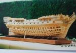
mij reacted to AntonyUK in Xebec by mij - FINISHED - 1:60 scale
Hi Mij.
The ship is progressing very nicely.
That method of shaping and cutting the cannon carages is used a lot by the me people on this site. Worked for me as well
Please keep the photos coming.
This build is interesting as I like the shape of the ship and the style.
Regards Antony.
-
mij reacted to captainbob in Xebec by mij - FINISHED - 1:60 scale
Looks like the eagle is about to catch the rabbit. Poor rabbit.
Bob
-
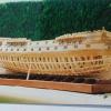
 mij got a reaction from GrandpaPhil in Xebec by mij - FINISHED - 1:60 scale
Milling the sides of the gun carriages
Drilling the holes for the 4mm blocks for the carriages
Turning a step suport
New carving of a rabbit
Model so far
-
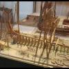
mij got a reaction from GrandpaPhil in Xebec by mij - FINISHED - 1:60 scale
I was not happy with the carving of the first eagle, so I carved another one from Boxwood.
I cut out the shape of the eagle first, then started the carving.
I took Antony`s advice in putting a light stain on the carving to bring out the detail.
I used French polish and linseed oil.
Carving with the stain on.
Eagle fitted to the stern of the ship.