

woodrat
-
Posts
779 -
Joined
-
Last visited
Reputation Activity
-

 woodrat got a reaction from GConiglio in Venetian Carrack or Cocha by woodrat - FINISHED - 1/64
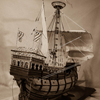
The quarterdeck beams also project through the side planking
Progress on the poop and quarterdeck
note the characteristic vertical timbers on the ships hull to give extra rigidity and protection to the hull
-
 woodrat got a reaction from canoe21 in Venetian Carrack or Cocha by woodrat - FINISHED - 1/64
tail frames are positioned at each end of the keel
Calculation of the narrowing of the frames between the master frame and the tail frames used the geometric "mezza lune" technique. rising of floors can also be calculated by a geometric technique
using these techniques, a half hull block model of the central hull was made and faired
As was done by the original shipwrights of the venetian Arsenale, ribbands were then used to make the bow and stern frames.
]
lines were taken off at each station
-
 woodrat got a reaction from Meriadoc Brandybuck in Venetian Carrack or Cocha by woodrat - FINISHED - 1/64
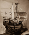
The following is a close reconstruction of the vessel, a carrack or cocha, illustrated in the 1445 document by Zorzi Trombetta da Modone ( also known as Timbotta). Fortunately for us, the dimensions of this hull were recorded on the original drawing of the hull, which enables a fairly close attempt at reconstruction possible.
The Trombetta nave circa1445
Venetian Carrack by Woodrat 1/64
Page 1:
Index
· Overview of Trombetta nave
· Design of midship frame
· Narrowing with mezza lune
· Construction of half-hull model
Page 2
· Lines from half-hull
· Plan for full hull build plank on bulkhead
Page 3
· Keel and posts: the backbone
· Bulkheads
· Main deck framing
· Transversal bitt
· Wales
· Start planking
Page4
· Complete planking
· Stern timbers
· Scuppers
· Main deck planking
· Main hatch
· Half deck
· Accommodation beneath half deck
· Steering mechanism
Page 5
· Planking half-deck
· Knees on half deck and waist
· Framing and planking poop deck
· Seats of ease
· Sterncastle construction
· Windlass
· Hawse holes
· Foremast step
· Forecastle framing
· Framing Great Arch starts
Page 6
· Completion of Great Arch
· Clinker planking of forecastle
· Planking and completion of forecastle
· External hull riders
Page 7
· Accommodation on the half deck
· Roofing of the half deck accommodation
· Knights
Page 8
· Figurehead
· Sterncastle construction
· Forecastle shelter
Page 9
· Grapnel
· Stern gallery and blinds
Page 10
· Capstan
· Rudder
· Pumps
Page 11
· Built-up mainmast
· Loading port
· Ventilation scuttles
· Mast partners and wedges
Page 12
· Blocks
· Standing rigging:
Page 13
· Standing rigging: mainstay
· More blocks
Page 14
· main shrouds
· mainyard
page 15
· halyards
· mainsail
· Crew figures
Page 16
· Molding of mainsail and bonnet
· Maintop
Page 17
· Further details of mainsail
· Jacob’s ladder
· Running rigging main
· Parrels and parrel tackle
Page 18
· Mainsail set
· Mizzen yard, sail
·
Page 19
· Mizzen mast standing rigging
· Mizzen partners and wedges
· Mizzen sail and running rigging
· Mizzen parrels, halyards and tackle
Page 20
· Final figurehead
· Completed ship with flags and pennants
Page 21
· Stand
We start:
The lines for the master frame and sheer were based on the extant material available from contemporary sources
note the rounded bow and stern, the projecting deck timbers, the high forecastle with its "great arch" below and the characteristic clinkered planking below the castle. The temporary lashed shelters attached to the fore and stern castles were presumably covered with awnings
to show another illustration of the great arch
a detail from the arrival of St Ursula at Cologne by Carpaccio. A contemporary view of carracks.
a careened carrack by Botticelli showing deck
detail
a carrack by Bonfigli 1485 showing the transversal bitt projecting below the forecastle whch is also seen on the Trombetta document
A roughly contemporary method of constructing a master-frame by Pre Theodoro
]This my attempt at a master-frame. All other hull frames are based on this.
Dick
-
 woodrat reacted to SJSoane in HMS Bellona 1760 by SJSoane - Scale 1:64 - English 74-gun - as designed
Hi everyone,
I finally got time over the holidays to get back into the shop and to check out the website. Thank you Ron, and Sailor 123... for your comments. The 74 gun ship of the mid 18th century has the perfect balance of form and function--I learn something new every day about how elegantly the shipwrights met a functional need with a beautiful form. Guy, I would be happy to see anything you might turn up on the Bellona.
I finally finished the gun deck framing. I did it in record time, compared to my previous work. I followed Gaetan's advice from some time ago, to keep working systematically at the same task, and it will become easier and faster. I worked out a systematic way of numbering the ledges, and I was able to do each process on each piece, before going back to do the next process on each piece. It helped with a rhythm, and it meant the whole deck was built up in each stage. It was harder that way to say that I had finished a few more bays, and could come back later for the remaining bays. I had to keep working to see any real progress, and then it was all done. It seemed to work for me!
I counted up. There are 525 pieces in the deck framing itself--beams, carlings, ledges, and knees. And 856 mortices.
I am moving on to framing the stern, for a nice change of scenery. I have made some very interesting discoveries about the Bellona framing, while drafting it up. More on that later.
Best wishes,
Mark
-
woodrat reacted to Erebus and Terror in HMS Terror by Erebus and Terror - FINISHED - Scale 1:48 - POB - as fitted for polar service in 1845
TERROR MODIFIED: THE HISTORIC PLANS (Part 1)
As outlined in a previous post, HMS Terror, originally designed as a bomb ship, was extensively modified three times for separate polar expeditions. Like all bomb vessels, she was already highly specialized, with an exceptionally strong frame built to withstand the punishing recoil of her two massive mortars, and a spacious hold for storing munitions (for an excellent discussion of the Terror’s original configuration, please consult Ware [1991]). To build an accurate model of the Terror as fitted for the 1845 expedition requires concatenating design information from all of the plans as well as data from other historical sources. The plans discussed here are preserved at the National Maritime Museum in Greenwich, and copies are available for purchase from their online image library. Detailed images of the plans are also presented in Ware (1991).
1812 Sheets A full set of plans “as designed” and dated March 30th, 1812, exist for HMS Terror; these are shared with her identical sister ship HMS Beelzebub. It is important to note that HMS Vesuvius plans are virtually indistinguishable and the two sets only differ in minor details (for example the scarph joints on the keel are not depicted in the Vesuvius plans). HMS Terror was so extensively modified that its final 1845 form bore little outward resemblance to her original design. The 1812 plans are critical, however, as they are the only drawings that depict her sheer, half breadth, and body plans, lines, framing configuration, keel and keelson construction, and stem and stern architecture.
1836 Sheets HMS Terror’s first extensive modification began in 1835 and is outlined in a series of plans dated March 1836 (and later December 1837) which depict the inboard profile and all decks. The plans are extremely important because they illustrate the fundamental refit of the Terror - and thus represent her final overall size and shape of as she appeared in 1845. The plans also document some important innovations for polar exploration that would be adopted by all subsequent polar expeditions (for an excellent overview see Battersby and Carney 2011).
Perhaps the most extensive modification depicted in these documents was the creation a flush deck with two layers of thee inch planking to increase strength. Though not depicted on the plans, contemporary images by Owen Stanley reveal that the copper sheathing on the Terror’s hull below the waterline was removed as protection from shipworm was not needed in the freezing waters of the Arctic. In its place, a cross-shaped series of thick copper reinforcement plates were riveted to the bow to protect against ice damage.
The ship’s profile was modified significantly as well. The stern galleries were removed (to eliminate any projection that would catch the ice), and the stern, at the position of the upper and lower decks, was both lengthened and widened, presumably to provide more space on these decks. The bow was altered as well, with the keel simplified and the ship lengthened overall. It is uncertain if the cant frames were altered or if the bow was simply bolstered behind the new copper reinforcing plates (a strong likelihood), but the plans clearly depict a forward change in the overall frame position.
On the interior, the Terror’s bow was reinforced with solid oak chocks bolted to the stemson, forming a solid mass of wood ranging between 4 and 8 feet thick from the wale down to the keelson. In an effort to strengthen and streamline her contours against the grasping ice, each of her chock channels were individually filled in and planked over. Thick iron plates were added to their upper surface, and the chains were replaced with solid iron plates bolted to the planked chocks. A spare rudder was suspended in a special well just behind the mainmast which penetrated from the upper deck down to the hold.
According to the inboard profile, the Terror’s mast positions were moved forward slightly and the rake of her masts, particularly the mizzenmast, appear to have been altered. It is uncertain when these modifications occurred, but they were probably done to improve the sailing qualities of the vessel (see previous post). In fact, they might have been undertaken during extensive repairs after the Terror was nearly wrecked in Portugal in 1828.
A cistern for melting ice was added to the ship’s stove, and 47 large iron storage tanks were added to the hold for water and other provisions. A novel addition was a hot water heating system fueled by a massive furnace in the orlop deck. The system functioned by pumping warm water through a complex series of pipes into the crew’s quarters on the lower deck. The furnace was an abject failure; it never worked as designed and George Back (1838) reported that it constantly had to be dismantled and repaired:
Perhaps the most overlooked innovation instituted during the 1835 refit was a system of watertight bulkheads designed to make the ship unsinkable. The concept of airtight chambers appears to have been the invention of Sir Robert Seppings and was first implemented by Sir Edward Belcher on HMS Aetna (Belcher 1870: 156). As Belcher described, “the Terror was the model ship” for an entirely new coal-based bulkhead system and it was to be used by him in the abortive rescue of the stranded whalers in 1835 (see previous post). He describes the system thusly (Belcher 1870:156):
Though Back (1838) gave them no credit, the bulkheads undoubtedly helped keep the Terror afloat during her harrowing return journey across the Atlantic. As Belcher (1870:156) described:
The Naval authority must have agreed with Belcher, as the 1839 midships section and hold plan (see below) display that the bulkhead system was incorporated into the Erebus with little apparent modification. The 1839 midships section shows that the bulkheads were constructed contiguous with the frames in the hold and orlop decks and were lined with “two thickness of 1 ½ inch African [board] wrought diagonally across each other”.
References:
Back, George R.
1838 Narrative of an Expedition in H.M.S. Terror, Undertaken with a View to Geographical Discovery on the Arctic Shores in the Year 1836-7. John Murray, London.
Battersby, William, and Carney, Peter
2011 Equipping HM Ships Erebus and Terror, 1845. International Journal for the History of Engineering & Technology 81(2):192-211.
Belcher, Sir Edward
1870 Admiral Belcher’s Remarks on Bulkheads. Transactions of the Institution of Naval Architects 11:155-156.
Ware, Chris.
1991 The Bomb Vessel: Shore Bombardment Ships of the Age of Sail. Naval Institute Press, Annapolis. -
 woodrat got a reaction from Salty Sea Dog in Venetian Carrack or Cocha by woodrat - FINISHED - 1/64
Having taken off the lines the solid half-hull was cut down to main deck level. The side timbers are seen.
main wales are seen bracketting the deck beams transom framing is seen
The hull was then planked. Note the projectiing deck beams at forward half of main deck and hold
The main deck was planked
The supporting structure of the forecastle was guessed at and the clinker planking below the forecastle was installed
the transversal bitt was installed
the horizontal clinker planking was installed to match the original drawing
The view from the other side
Dick
-
woodrat got a reaction from Salty Sea Dog in Venetian Carrack or Cocha by woodrat - FINISHED - 1/64
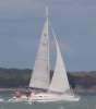
sort of like a majestic duck, wouldn't you say? Dick
-
 woodrat got a reaction from GrandpaPhil in USF Essex by woodrat - FINISHED - Scale 1:64 - Fully Framed - from Portia Takakjian plans
Thanks, Phebe and Happy New Year!
-
woodrat got a reaction from GrandpaPhil in USF Essex by woodrat - FINISHED - Scale 1:64 - Fully Framed - from Portia Takakjian plans
some views of the fearsome mohawk figurehead
-
woodrat got a reaction from GrandpaPhil in USF Essex by woodrat - FINISHED - Scale 1:64 - Fully Framed - from Portia Takakjian plans
Thank you Christian.
Cutting slots with cross-slide
deadeyes in place.
companionway
pinrails
-
 woodrat got a reaction from ggrieco in Venetian Carrack or Cocha by woodrat - FINISHED - 1/64
tail frames are positioned at each end of the keel
Calculation of the narrowing of the frames between the master frame and the tail frames used the geometric "mezza lune" technique. rising of floors can also be calculated by a geometric technique
using these techniques, a half hull block model of the central hull was made and faired
As was done by the original shipwrights of the venetian Arsenale, ribbands were then used to make the bow and stern frames.
]
lines were taken off at each station
-
 woodrat got a reaction from tarbrush in USF Essex by woodrat - FINISHED - Scale 1:64 - Fully Framed - from Portia Takakjian plans
Thanks, Phebe and Happy New Year!
-
 woodrat got a reaction from dgbot in Venetian Carrack or Cocha by woodrat - FINISHED - 1/64
tail frames are positioned at each end of the keel
Calculation of the narrowing of the frames between the master frame and the tail frames used the geometric "mezza lune" technique. rising of floors can also be calculated by a geometric technique
using these techniques, a half hull block model of the central hull was made and faired
As was done by the original shipwrights of the venetian Arsenale, ribbands were then used to make the bow and stern frames.
]
lines were taken off at each station
-
 woodrat got a reaction from mikegerber in Venetian Carrack or Cocha by woodrat - FINISHED - 1/64
tail frames are positioned at each end of the keel
Calculation of the narrowing of the frames between the master frame and the tail frames used the geometric "mezza lune" technique. rising of floors can also be calculated by a geometric technique
using these techniques, a half hull block model of the central hull was made and faired
As was done by the original shipwrights of the venetian Arsenale, ribbands were then used to make the bow and stern frames.
]
lines were taken off at each station
-
woodrat got a reaction from tarbrush in Venetian Carrack or Cocha by woodrat - FINISHED - 1/64
The following is a close reconstruction of the vessel, a carrack or cocha, illustrated in the 1445 document by Zorzi Trombetta da Modone ( also known as Timbotta). Fortunately for us, the dimensions of this hull were recorded on the original drawing of the hull, which enables a fairly close attempt at reconstruction possible.
The Trombetta nave circa1445
Venetian Carrack by Woodrat 1/64
Page 1:
Index
· Overview of Trombetta nave
· Design of midship frame
· Narrowing with mezza lune
· Construction of half-hull model
Page 2
· Lines from half-hull
· Plan for full hull build plank on bulkhead
Page 3
· Keel and posts: the backbone
· Bulkheads
· Main deck framing
· Transversal bitt
· Wales
· Start planking
Page4
· Complete planking
· Stern timbers
· Scuppers
· Main deck planking
· Main hatch
· Half deck
· Accommodation beneath half deck
· Steering mechanism
Page 5
· Planking half-deck
· Knees on half deck and waist
· Framing and planking poop deck
· Seats of ease
· Sterncastle construction
· Windlass
· Hawse holes
· Foremast step
· Forecastle framing
· Framing Great Arch starts
Page 6
· Completion of Great Arch
· Clinker planking of forecastle
· Planking and completion of forecastle
· External hull riders
Page 7
· Accommodation on the half deck
· Roofing of the half deck accommodation
· Knights
Page 8
· Figurehead
· Sterncastle construction
· Forecastle shelter
Page 9
· Grapnel
· Stern gallery and blinds
Page 10
· Capstan
· Rudder
· Pumps
Page 11
· Built-up mainmast
· Loading port
· Ventilation scuttles
· Mast partners and wedges
Page 12
· Blocks
· Standing rigging:
Page 13
· Standing rigging: mainstay
· More blocks
Page 14
· main shrouds
· mainyard
page 15
· halyards
· mainsail
· Crew figures
Page 16
· Molding of mainsail and bonnet
· Maintop
Page 17
· Further details of mainsail
· Jacob’s ladder
· Running rigging main
· Parrels and parrel tackle
Page 18
· Mainsail set
· Mizzen yard, sail
·
Page 19
· Mizzen mast standing rigging
· Mizzen partners and wedges
· Mizzen sail and running rigging
· Mizzen parrels, halyards and tackle
Page 20
· Final figurehead
· Completed ship with flags and pennants
Page 21
· Stand
We start:
The lines for the master frame and sheer were based on the extant material available from contemporary sources
note the rounded bow and stern, the projecting deck timbers, the high forecastle with its "great arch" below and the characteristic clinkered planking below the castle. The temporary lashed shelters attached to the fore and stern castles were presumably covered with awnings
to show another illustration of the great arch
a detail from the arrival of St Ursula at Cologne by Carpaccio. A contemporary view of carracks.
a careened carrack by Botticelli showing deck
detail
a carrack by Bonfigli 1485 showing the transversal bitt projecting below the forecastle whch is also seen on the Trombetta document
A roughly contemporary method of constructing a master-frame by Pre Theodoro
]This my attempt at a master-frame. All other hull frames are based on this.
Dick
-
woodrat reacted to mtaylor in Licorne by mtaylor - 3/16" scale - POF - TERMINATED LOG
Hmm... not quite November of 2014 as I promised Sjors, but here's the latest. I finished the gunports (thank heavens it's not a 74), added the ebony wales (chain and main), and began working towards the top rails. The red arrow points to where I need to fill in with either plum or swiss pear. I'm undecided at this moment and waiting to see how some test wood looks with the Wipe on Poly.
I also cut out every other frame between the build board and where the cap rail will be in the midship area. I need to rotate her around and do the other side now.
As for the ebony... if I ever mention on another ship, that I'm planning on using ebony, please do unto me which the Victory did unto Bucentaur at Trafalgar. Just unload a broadside. Aggrevating stuff. The epoxy wasn't holding and required some gel type CA. I think pear with ebony stain would look as good.
-
woodrat got a reaction from ggrieco in Venetian Carrack or Cocha by woodrat - FINISHED - 1/64
The following is a close reconstruction of the vessel, a carrack or cocha, illustrated in the 1445 document by Zorzi Trombetta da Modone ( also known as Timbotta). Fortunately for us, the dimensions of this hull were recorded on the original drawing of the hull, which enables a fairly close attempt at reconstruction possible.
The Trombetta nave circa1445
Venetian Carrack by Woodrat 1/64
Page 1:
Index
· Overview of Trombetta nave
· Design of midship frame
· Narrowing with mezza lune
· Construction of half-hull model
Page 2
· Lines from half-hull
· Plan for full hull build plank on bulkhead
Page 3
· Keel and posts: the backbone
· Bulkheads
· Main deck framing
· Transversal bitt
· Wales
· Start planking
Page4
· Complete planking
· Stern timbers
· Scuppers
· Main deck planking
· Main hatch
· Half deck
· Accommodation beneath half deck
· Steering mechanism
Page 5
· Planking half-deck
· Knees on half deck and waist
· Framing and planking poop deck
· Seats of ease
· Sterncastle construction
· Windlass
· Hawse holes
· Foremast step
· Forecastle framing
· Framing Great Arch starts
Page 6
· Completion of Great Arch
· Clinker planking of forecastle
· Planking and completion of forecastle
· External hull riders
Page 7
· Accommodation on the half deck
· Roofing of the half deck accommodation
· Knights
Page 8
· Figurehead
· Sterncastle construction
· Forecastle shelter
Page 9
· Grapnel
· Stern gallery and blinds
Page 10
· Capstan
· Rudder
· Pumps
Page 11
· Built-up mainmast
· Loading port
· Ventilation scuttles
· Mast partners and wedges
Page 12
· Blocks
· Standing rigging:
Page 13
· Standing rigging: mainstay
· More blocks
Page 14
· main shrouds
· mainyard
page 15
· halyards
· mainsail
· Crew figures
Page 16
· Molding of mainsail and bonnet
· Maintop
Page 17
· Further details of mainsail
· Jacob’s ladder
· Running rigging main
· Parrels and parrel tackle
Page 18
· Mainsail set
· Mizzen yard, sail
·
Page 19
· Mizzen mast standing rigging
· Mizzen partners and wedges
· Mizzen sail and running rigging
· Mizzen parrels, halyards and tackle
Page 20
· Final figurehead
· Completed ship with flags and pennants
Page 21
· Stand
We start:
The lines for the master frame and sheer were based on the extant material available from contemporary sources
note the rounded bow and stern, the projecting deck timbers, the high forecastle with its "great arch" below and the characteristic clinkered planking below the castle. The temporary lashed shelters attached to the fore and stern castles were presumably covered with awnings
to show another illustration of the great arch
a detail from the arrival of St Ursula at Cologne by Carpaccio. A contemporary view of carracks.
a careened carrack by Botticelli showing deck
detail
a carrack by Bonfigli 1485 showing the transversal bitt projecting below the forecastle whch is also seen on the Trombetta document
A roughly contemporary method of constructing a master-frame by Pre Theodoro
]This my attempt at a master-frame. All other hull frames are based on this.
Dick
-
woodrat got a reaction from GrandpaPhil in USF Essex by woodrat - FINISHED - Scale 1:64 - Fully Framed - from Portia Takakjian plans
I initally did the seats of ease as per the AOTS drawing but, after ribald comments from various MSW members about wet bums in any sort of sea, I redid them in a more traditional way.
the old seats for hardy sailors
that's better (and drier!)
-
 woodrat got a reaction from cpt. Tom in USF Essex by woodrat - FINISHED - Scale 1:64 - Fully Framed - from Portia Takakjian plans
some views of the fearsome mohawk figurehead
-
woodrat got a reaction from tarbrush in USF Essex by woodrat - FINISHED - Scale 1:64 - Fully Framed - from Portia Takakjian plans
I initally did the seats of ease as per the AOTS drawing but, after ribald comments from various MSW members about wet bums in any sort of sea, I redid them in a more traditional way.
the old seats for hardy sailors
that's better (and drier!)
-
 woodrat got a reaction from Mike Y in Le Gros Ventre 1767 by woodrat - Scale 1:48 - POF - French exploration vessel
here is the completion of the framing of the bow module. Phew!
The jarrah has been oiled to nourish the wood. It wont remain shiny and the wood will darken.
hawse holes are yet to be made.
-
 woodrat got a reaction from SailorGreg in USF Essex by woodrat - FINISHED - Scale 1:64 - Fully Framed - from Portia Takakjian plans
I initally did the seats of ease as per the AOTS drawing but, after ribald comments from various MSW members about wet bums in any sort of sea, I redid them in a more traditional way.
the old seats for hardy sailors
that's better (and drier!)
-
 woodrat got a reaction from davyboy in USF Essex by woodrat - FINISHED - Scale 1:64 - Fully Framed - from Portia Takakjian plans
I initally did the seats of ease as per the AOTS drawing but, after ribald comments from various MSW members about wet bums in any sort of sea, I redid them in a more traditional way.
the old seats for hardy sailors
that's better (and drier!)
-
woodrat got a reaction from GrandpaPhil in Le Gros Ventre 1767 by woodrat - Scale 1:48 - POF - French exploration vessel
here is the completion of the framing of the bow module. Phew!
The jarrah has been oiled to nourish the wood. It wont remain shiny and the wood will darken.
hawse holes are yet to be made.
-
 woodrat got a reaction from WackoWolf in Le Gros Ventre 1767 by woodrat - Scale 1:48 - POF - French exploration vessel
No, Slog. it would seem that the french have a good sense of humour. The name IS Le Gros Ventre and it does mean Fat Belly Dick
More bloody hawse pieces!!!