HOLIDAY DONATION DRIVE - SUPPORT MSW - DO YOUR PART TO KEEP THIS GREAT FORUM GOING! (Only 36 donations so far out of 49,000 members - C'mon guys!)
×


Fam
-
Posts
185 -
Joined
-
Last visited
Content Type
Profiles
Forums
Gallery
Events
Everything posted by Fam
-
 Thank you Dirk a part from the trade name, what type of material is 'zapon laquer'? And how do you apply it (brush, airbrush, other mean), in the hypotesis I manage to find something similar here in Italy? I've only found this description: http://cameo.mfa.org/wiki/Zapon_lacquer Thank you so much and bye Fam
 -
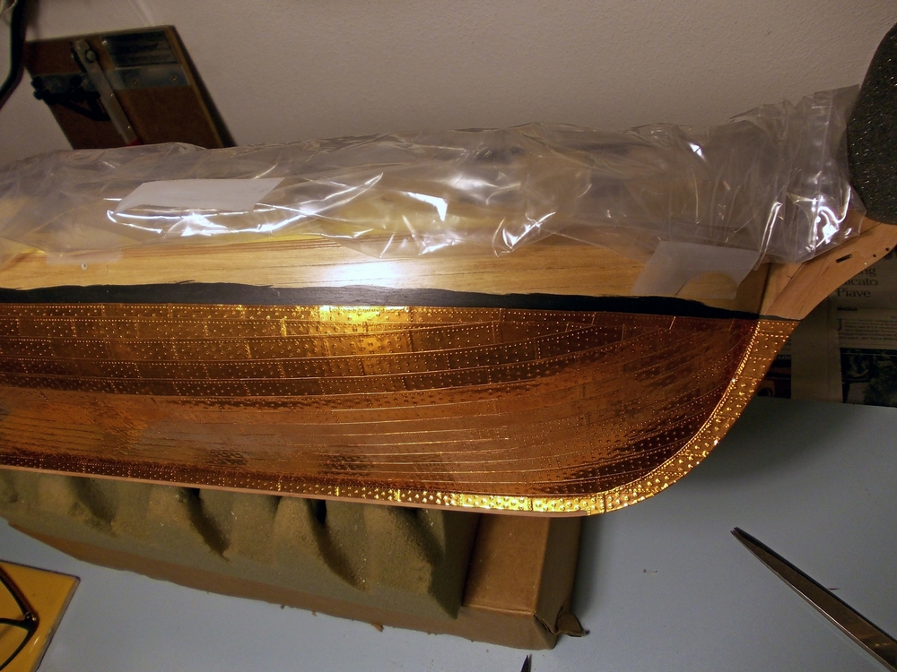
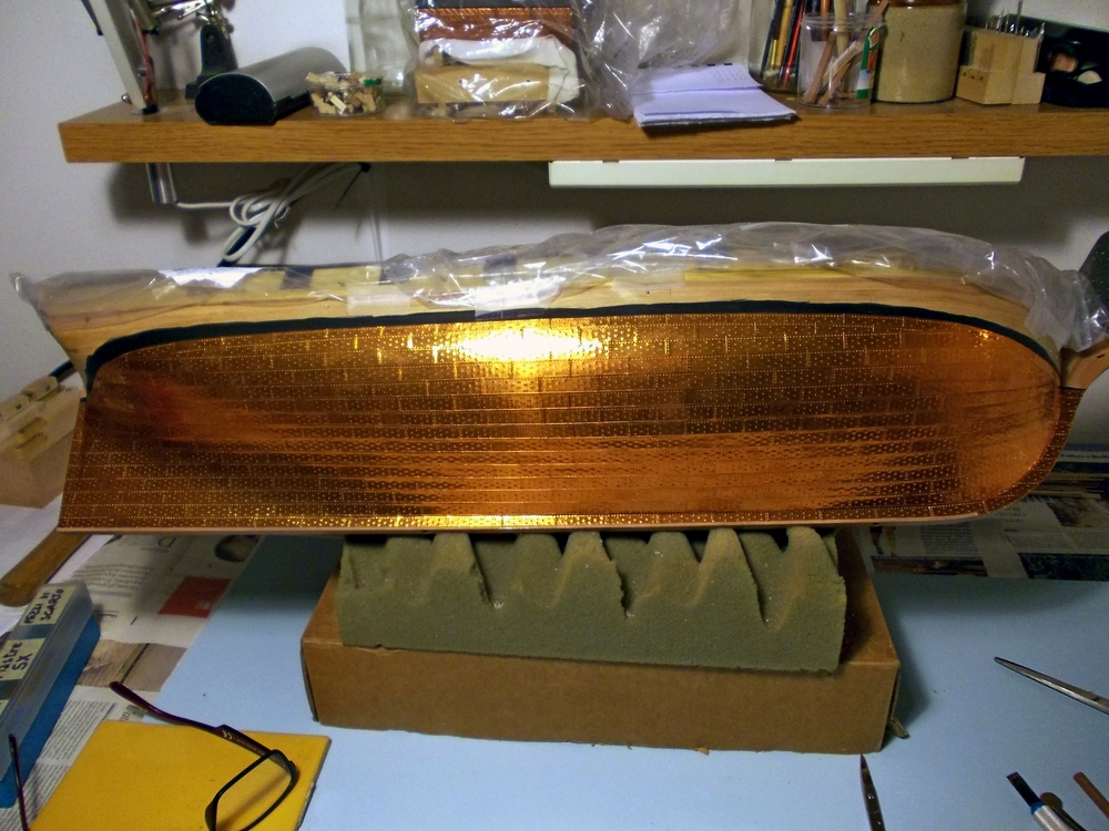
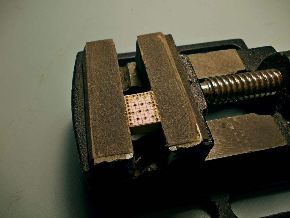
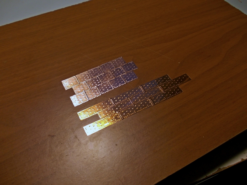
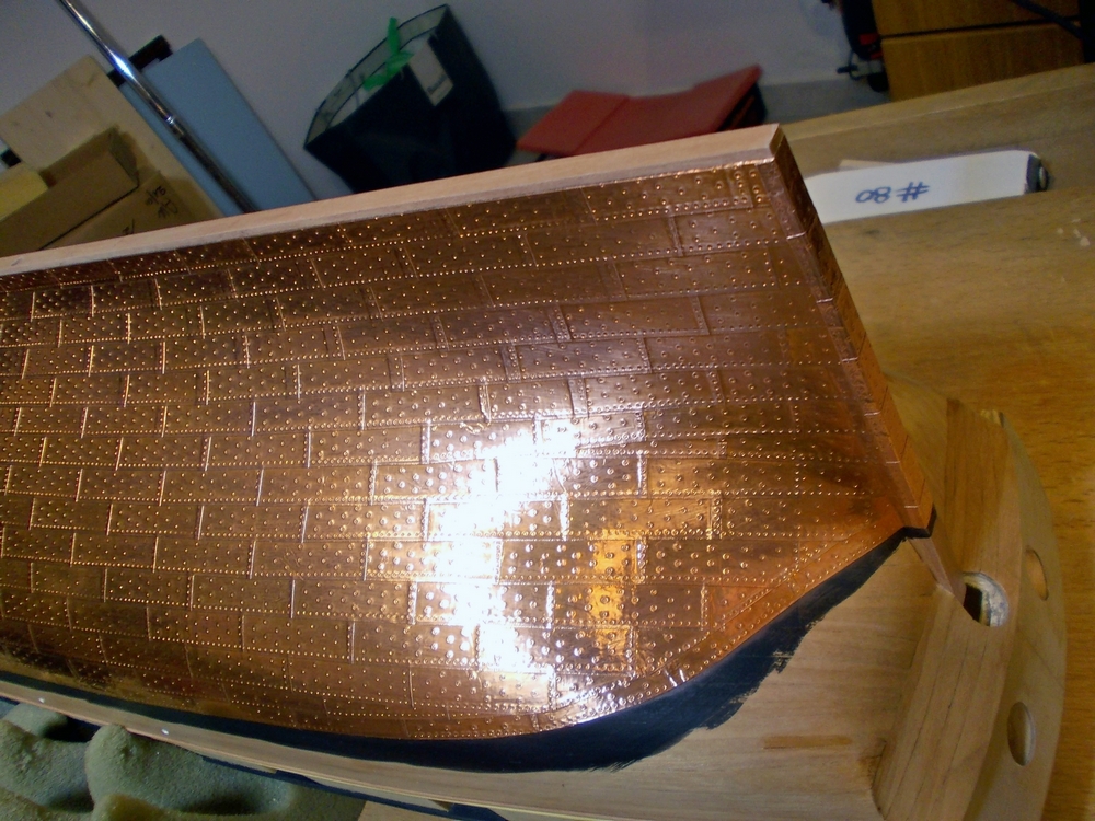
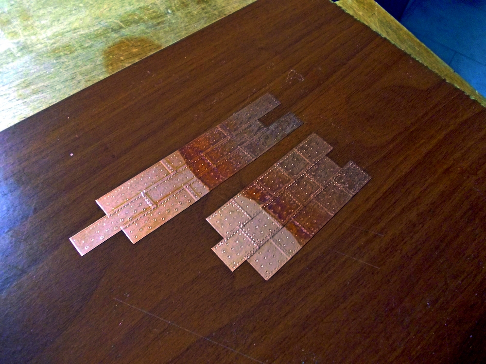
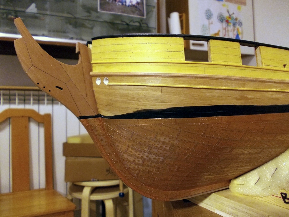
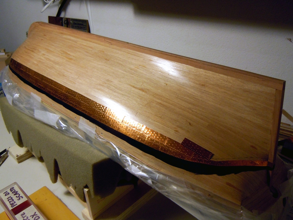
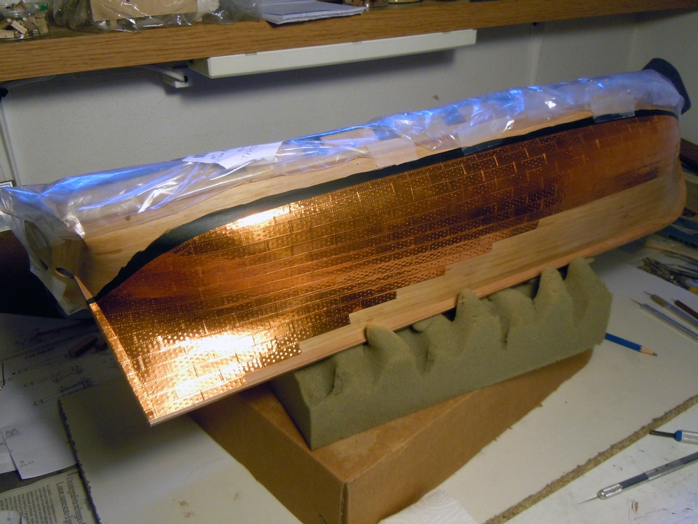
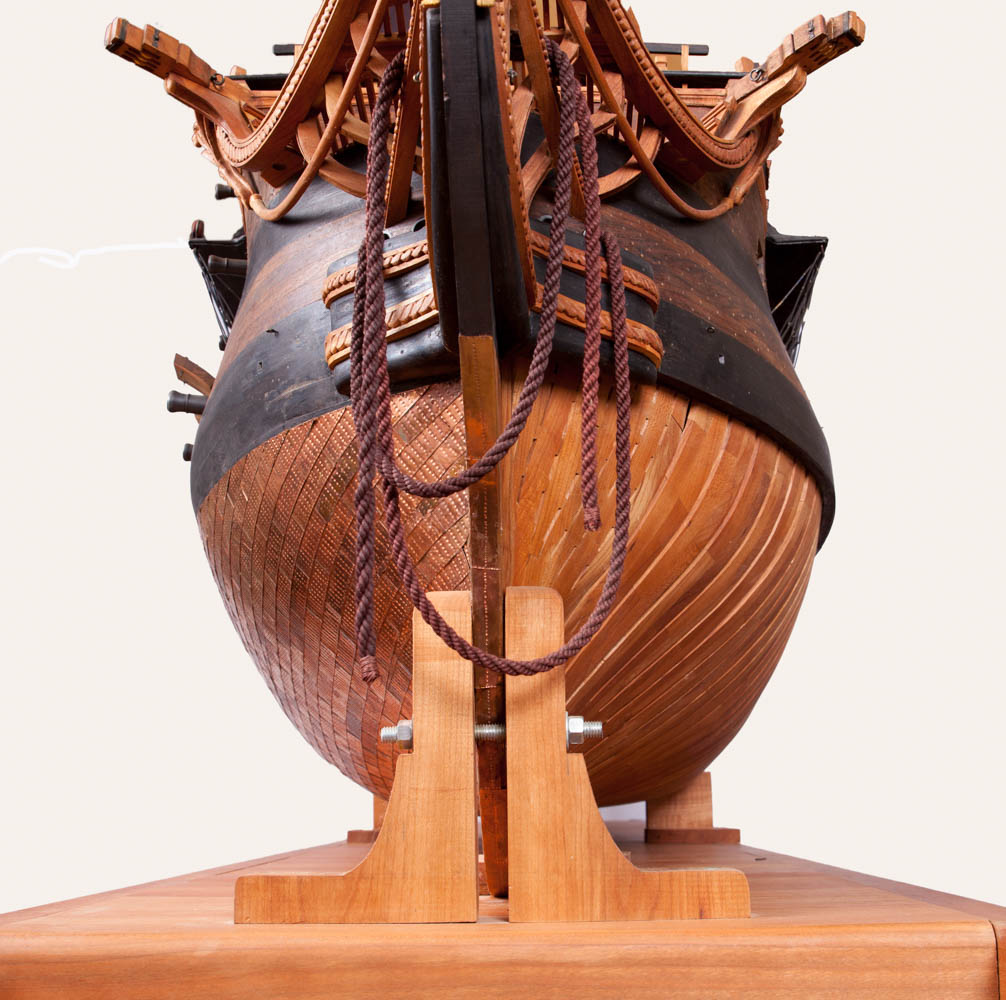
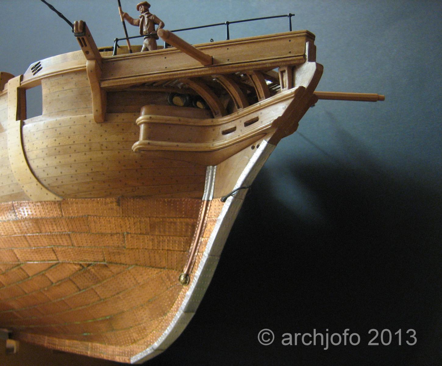
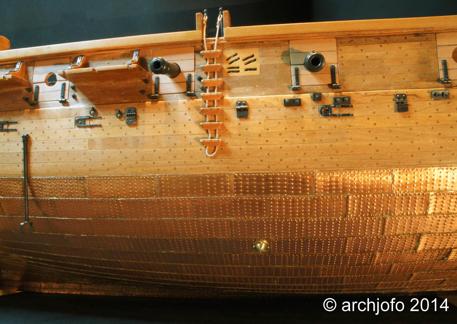
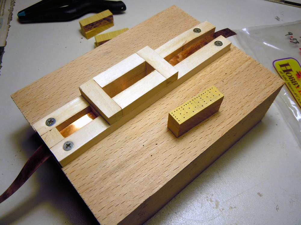
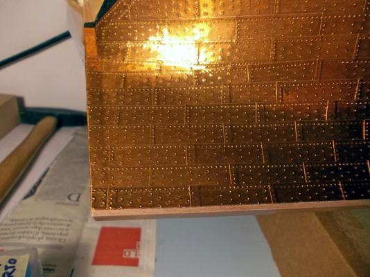
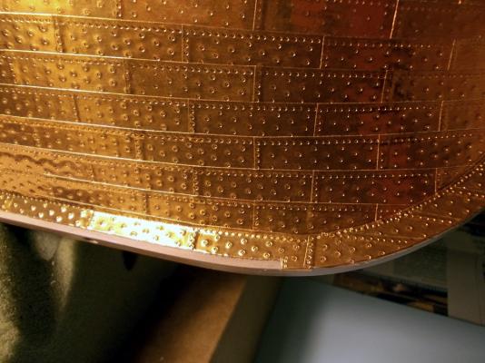
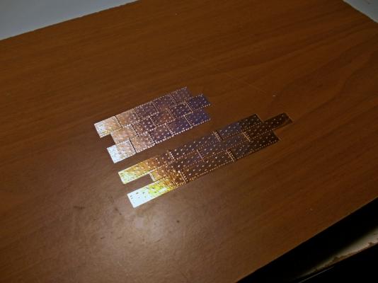
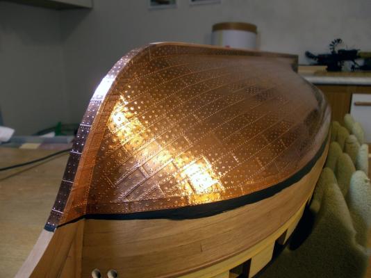
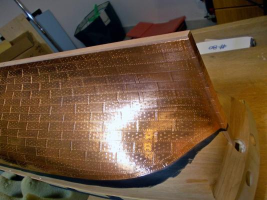
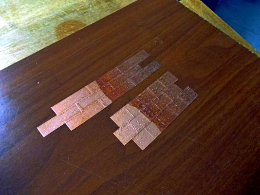
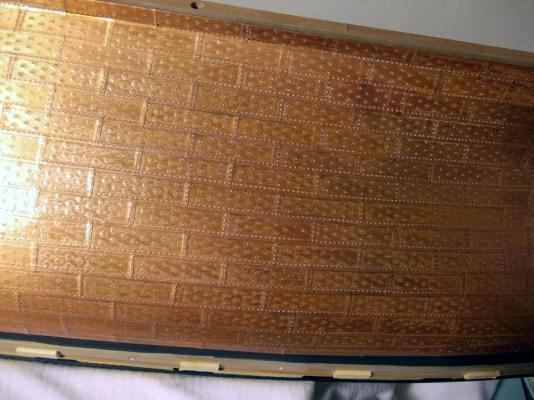
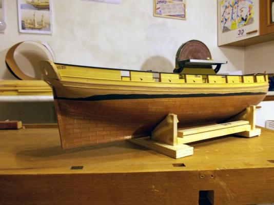
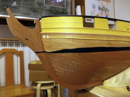
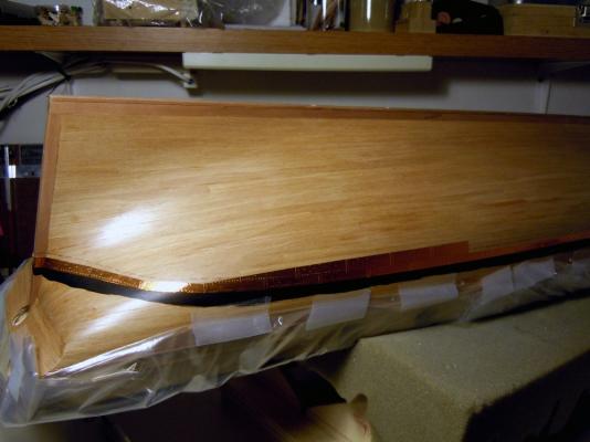
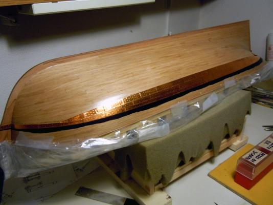
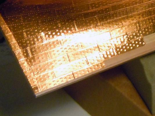
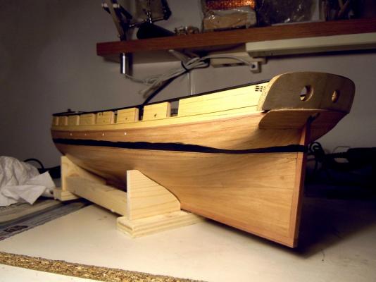
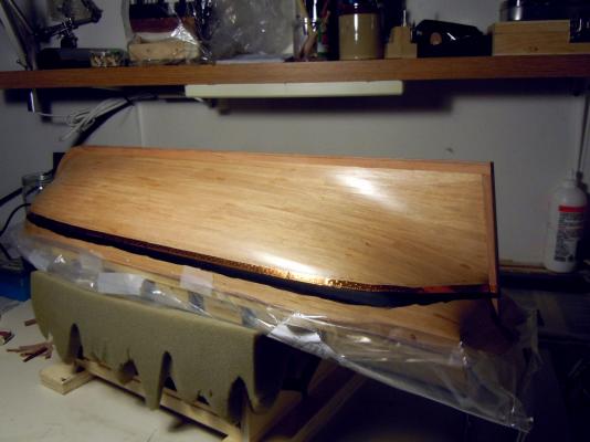
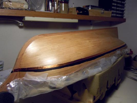
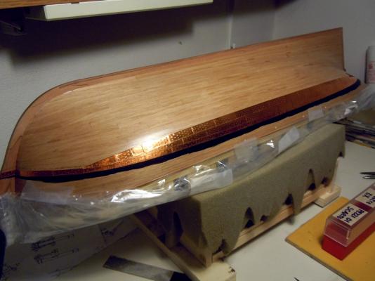
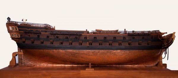
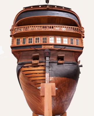
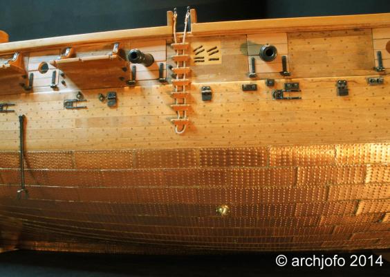
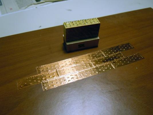
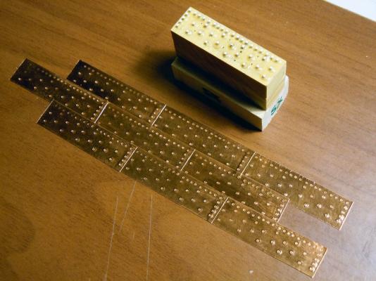
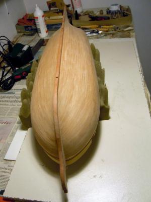
December 24th, 2015 Hi all as I promised, I’m able to show the completely coppered hull. Firstly a couple of pictures at an earlier stage, when the plates covering the keel thickness are still missing. I tried to adjust the color rendering so to match the real color of new copper, which is amazingly bright and shiny. The following pictures show how I set the copper foil into the narrow and shallow groove that separates the keel from the false-keel... I don’t know if the picture manages to render the effect... well it is not exactly like if the copper continues between the two parts, but is looking almost as I wanted. Next picture is how I prepared the stamp for the plates covering the keel width. The holes will house the steel needles used to stamp the simulated nails on the copper tape. There is no detail about these plates in the Ancre monography, but I needed a greater width to have some margin for bending each plate to the sides of the keel timbers. The keel is 7mm thick, as I wrote above, and I managed to find a copper tape 12.7mm wide. The layout of the nails is the same as for the other plates, just extended to the larger width of these plates. But, differently from the hull plates, I added another row of nails to the side edge, so that both left and right edges look correctly. I imagined that the curvature of the bow timbers profile would have caused the plates to wrinkle at the sides of keel. To minimize this, I decided to reduce the plates length to about a half of the length of the hull plates: I firstly tried with 20mm length, but the wrinkles were still present and quite difficult to avoid. At 15mm length (instead of the standard 33mm) I managed to avoid the buildup of these wrinkles. So the final size I chose is 12.7mm width and 15mm length. As for the hull plates, I started producing a small batch of plates for testing how they looked. When I laid the new plates on the side of those I’ve used for the first test, my heart almost missed a beat... OMG, the color was very different!!! More pinkish, as you can see in the following picture: Probably a different brand of copper, or a different surface finish, or whatever... I didn’t know what to think! I stopped working for a couple of days, thinking at what to do to fix this problem. Then just tried: degreased both copper types with acetone (nail polisher), then rubbed them with very fine steel wool ... and the miracle happened! I don’t know what the reason was, I cannot believe the older plates had already oxidized ... well I didn’t care: now both plates types showed the same color. Ok, let’s go forward: the amount of wide plates was not much, just about 20. So it was a job quickly done. The next two pictures show the final plates installed on bow timber and stern post... you can see that the colors are still different, I fixed it later. The last step of coppering was to try reducing the excessive shining of new copper by applying a weathering patina, so to simulate the natural ageing of copper. I used the recipe suggested by Dirk (Dubz), a mixture of vinegar and salt, with as much salt as can be added to the solution before it starts to fall to the bottom of the pot. I also heated the vinegar to melt a bit more salt... a super-saturated solution I think it’s called. Again, I used the tester plates to check the effect: What above picture is showing is much more than the real effect, but I wanted to show it because three different areas are visible: to the left is the original copper, in the middle is the copper just covered with some mixture and to the right is the copper after the mixture has dried. To be honest, I saw this result on the hull before, then I checked on the testers and noticed that a white patina had developed... in other words I was impatient to test the new technique and did not left enough time to the chemicals to complete their effects. The effect of the mixture was treble: immediately the copper changed color, taking a more brownish tone. Then it lost great part of its shine. And finally the white patina appeared, probably a side effect of the excess of salt in the mixture... Back to the hull: before applying the mixture I thoroughly degreased the entire hull with acetone, then passed all the plates with very fine steel wool... and the copper colors harmonized. Then applied the mixture in several coats, using a ragged piece of fabric that I dipped into the solution: in this way I tried to avoid leaving any excessive amount of the stuff on the copper. And this is the final effect: I’m now thinking at how to face this patina, even though I admit that I’m not disliking the final look ... A couple more shots of the coppered hull how as it is right now, before the shipyard was closed for Christmas holidays. I used a different camera, with much lower performance, and this is the reason for such different color rendering... You may see that I also added a third molding strip just below the water scuppers, an addition of the very last minutes. I’ve missed it during all my previous analysis of the plans, but discovered it when checking for the next job. I’ve used Yellowheart wood strips that I had available in the scrap parts box: don’t be surprised for the strange color matching, because all this area will be painted black. To set these strips I temporarily glued several 4.5mm wide spacers below the main molding (they are visible in the above picture), then used them as a guide for laying the new molding. Next job, in the first days of the New Year 2016, will be the cheeks that laterally support the knee-of-the-head ... stay tuned! I wish you Merry Christmas and a Happy and Prosperous New Year 2016 Fam


-
I can't imagine what you would be able to do at a larger scale...this is so fantastic, the quality and quantity of details, the cleanliness, the finish...no words to tell my admiration!! Fam
-
Thank you Johann, apreciated! I've now completed the starboard side and proceeding with the port side. I'm planning to complete the coppering before Christmas holidays, I will post several pictures soon I have a question for whoever has an answer: my keel, rudder-post and head timbers are 7mm thick but my copper tape is just 9.6mm wide. If I use it to cover the keel thickness, that gives just a poor 1.2mm of copper overlap to the sides of the timbers I fear this is a bit short, because probably I need some more width to have a row of nails on both sides of the copper plates... any idea, suggestion, comment? I would really appreciate! Thank you in advance My best regards *** EDIT *** I think I've found the solution: I managed to find a wider version, same brand, of the adhesive copper tape I'm already using .... 12.7mm width (or 1/2 inch) should be enough to solve my problem Cheers Fam
-
Thank you all for the likes and comments mtaylor I remember having read this somewhere here, maybe in Dirk's buildlog. The problem was, a part from what is asked by avsjerome2003 (which I believe is true), that probably the copper protection continued between the keel and the false keel. Or some other mean was used with the same scope. I initially applyed the two entire copper plates, then reminded having read this discussion and cut the two plates along the keel-shoe separation line. But the look was not enough, it was just like "cut-along" and not like "plate-wrapping-the-keel", don't know if it is clear enough... Also tried to press the copper plate into the joint line, but the joint is so tight that the result is...no difference. So now I'm thinking this: I'll remove these two plates, then will carve the joint line deeper and then will re-install the two plates trying to get a better look. Will show you the final result And... yes, I concur with you that hiding the planking is a pity... I thought about it and decided that should the result of my 2nd planking be close enough to the level of perfection Chuck is so easily getting, I would give up with coppering... well, it was quite far from that, so the final decision was easy :D Waterline: I'll do as you guys suggested and will live with it... another lesson learned, but the idea of trying removing the overlapped plates is really a nightmare to me!! Thank you all for your support Fam
-
Thank you both, my friends I really appreciate your comments ;-)
-
Thx Dirk You mean about the waterline or the keel shoe ?
-
December 7th, 2015 Hi guys, just a quick update from the coppering workshop… In general I’m quite pleased with the “reverse” method, it’s quite easy and the result is pleasant. I only hat to introduce 1 drop "plank" at stern and to taper the plates a little bit at stem, as shown in the pictures below. I only have a minor area of disappointment, that is the waterline close to poop: it should have got a nicely curved shape and instead it is a broken line, due to the length of the plates that does not permit following perfectly the waterline. I tried to cut the plates upper edge, but it was not enough. Unfortunately the waterline row of plates was the first installed, so now fixing this area by removing the affected plates and replacing with others (curved) is at risk of definitely damaging the surrounding plates, in an area that will be very visible in the model. Judge by yourself: Another issue is related to coppering the “shoe” board attached below the keel: this item was already discussed in Dirk’s buildlog of USS Syren, with pros and cons. Now in the latter picture I’ve shown the first two plates of the last row just cut at the lower edge line of the keel, thus leaving the “shoe” free from copper… I show you more in detail: What do you guys think about it? Should I leave it this way or should I replace the two plates with two complete plates, also covering the “shoe”? Opinions, comments and suggestions are more than welcome, as usual Regards Fam


-
Hi Sergio you are almost ready to start a mass production of boats... can I sub-contract to you the building of my three lifeboats? Have a nice building! Fam
-
Thank you all for the appreciation and the likes!
-
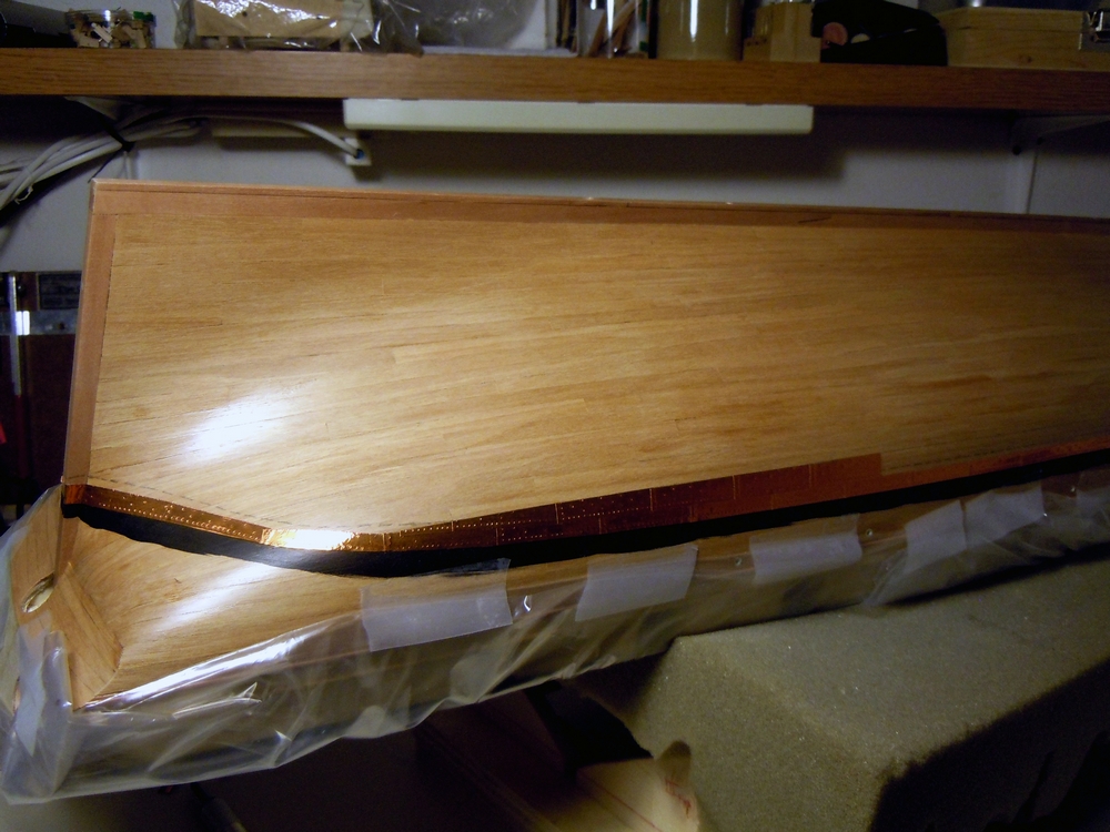
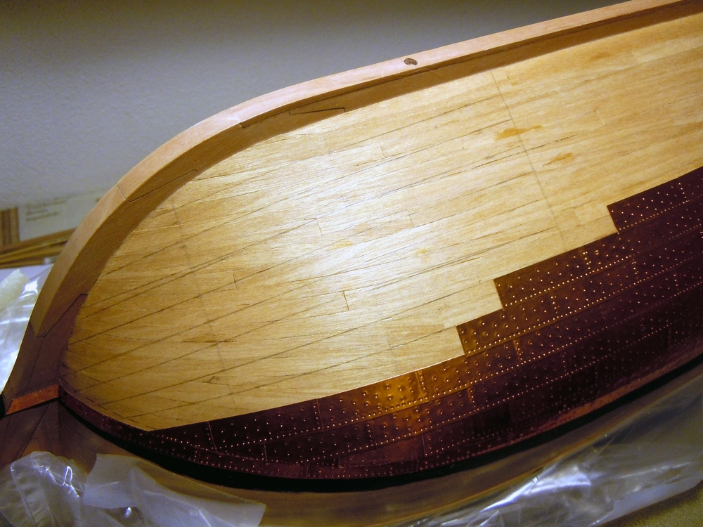
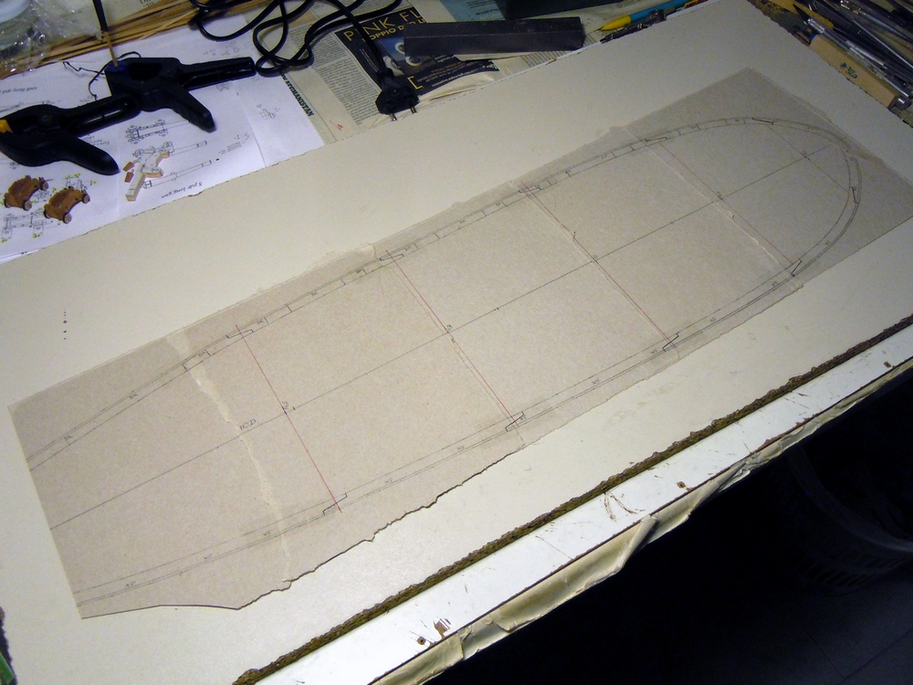
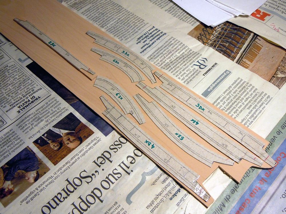
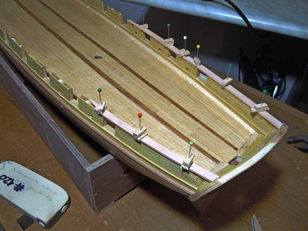
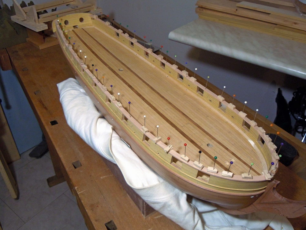
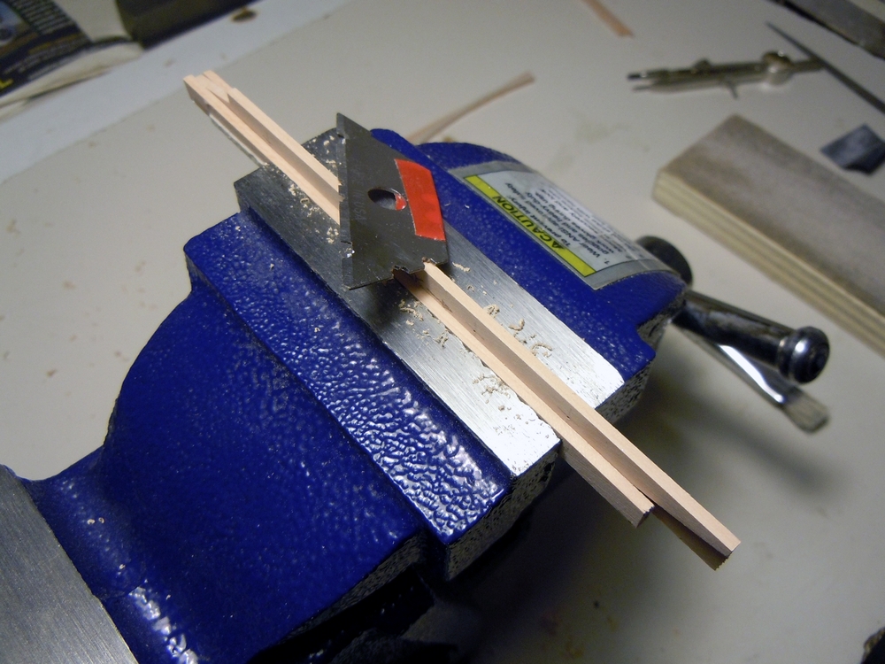
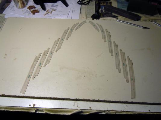
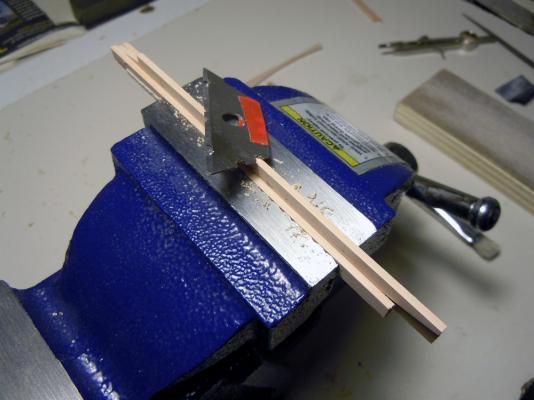
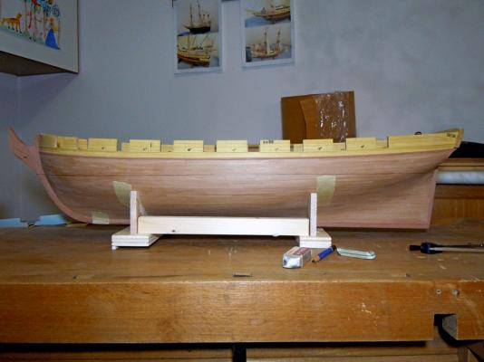
November 30th, 2015 … Continuation … Gunwales Next scheduled step was building the gunwales, as they complete the upper edge of the bulwarks, protect them and give also more strength, that is not bad considering the hull will be inverted for some time. The method is the same already described by my good friend JA, but I will show some more details about the procedure. First step is to draw the profile of the gunwales: I used a piece of scrap cardboard (Corn Flakes boxes ), laid it flat above the bulwarks and transferred the bulwarks profile to the underneath of the cardboard with a sharp pencil. The gunwales total width can be measured on the plans, which also show how they protrude about 1.5mm inside and outside the bulwarks. So I had to add another “parallel” line externally to the one already drawn, spaced 1.5mm away, and a second one internally to the existing line, at the correct distance to obtain the total width. The above is the final result, with several red lines also traced: the midship line (to check symmetry) and the lines showing how to split the gunwales in several pieces. I wanted to simulate the use of wood boards about 7-8m long, joined with scarph joints. So added these lines, drew the joints and cut the resulting pieces: Then glued these pieces to a 2mm thick Pearwood board and cut them out with a scroll-saw. Starting from the transom, I positioned the gunwale pieces on top of the bulwarks, alternating port and starboard sides to increase the visibility of any asymmetry. The pieces were held in position by pins inserted in the toptimbers and gunport side-lining pieces: Piece after piece after piece...I got to the bow optimizing the flow of boards and every joint. The gunwale boards have a composite profile on their internal and external edges, so I used the experienced technique of scrapers by cutting the required profile in a steel blade. Then locked every gunwale piece in a vise and scraped the two sides… ...with this result: To avoid any painting problem after the installation, I pre-stained the boards underside with black stain. Here are all the gunwales pieces: And finally the installation started. Here the problem was to firmly hold each piece pressed against the top of bulwarks, so to obtain a strong glued joint. The pin holes provided the needed reference for the alignment. Above is the final results completed and below the gunwales finished with black acrylic paint: two light coats, a light sanding, a third light coat as final finishing: The preparation for coppering was then concluded by painting a black area just few millimeters wide upward of the waterline: I wanted to avoid having the need to paint the hull down to the copper, and also wanted to avoid the need to protect the copper from overpainting, so prepared the base well in advance. The waterline is still visible below this painted area because it will be the reference for laying the first row of plates. And finally… coppering!! I protected the gunwales and inverted the hull. After a long exchange of PMs with Archjofo/Johannes (thank you very much, you were very kind!) I obtained several pictures of the hull of his Le Crèole corvette, which is coppered exactly the same way described in the monography of Le Cygnus brig (ref. above posts). The only difference is a single line of narrow copper plates at the waterline instead of four lines. So I started producing the plates for the waterline: they are as long as the main plates, 33mm corresponding to 1.60m in the real world, but only 5.5mm wide instead of 10mm (0.50m). The simulated nails heads are 0.6mm diameter, corresponding to about 30mm. They obviously have a different (mirrored) layout from port to starboard. Laying of the plates starts at the rudder post timber and proceeds forward, with an overlay of the plates by about 1mm (41mm in the real world). And I immediately had to face a problem… how to approximate a curved line with straight segments! The solution was probably to use curved plates, prepared ad-hoc by the master blacksmith of the shipyard. I simply used the prepared plates and cut the upper profile round, following the waterline. The lower profile of the plates waterline row results in a split-line, but it will be covered by the following rows of copper. The flow of the row at the bow is much easier: And these are the first two rows of standard plates completed yesterday night, with the few plates I had already prepared... unfortunately I had to temporarily close the blacksmith workshop because my relatives loudly protested for the hammering noise To find its correct shape (natura lcurvature line) I used a 10mm wide plank, placed on the hull and bent to naturally follow the curvature of the hull. The next rows are just following the upper profile of this first: Next days will be busy with the coppering. I will have also to prepare a third stamp for the plates covering the thickness of the keel-sternpost-stem timbers. Cheers Fam


-
Thank you Dirk!
-
Many thanks Druxey, I appreciate!
-
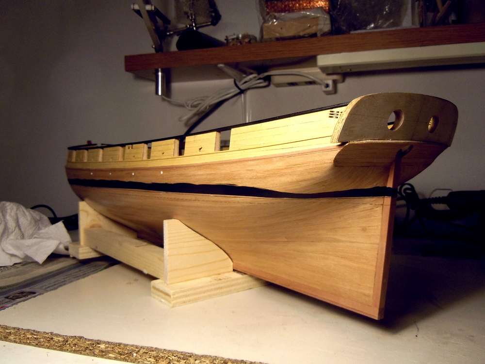
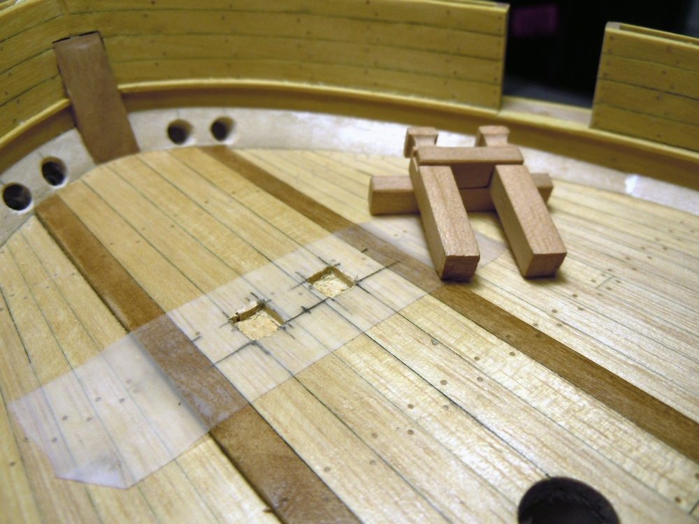
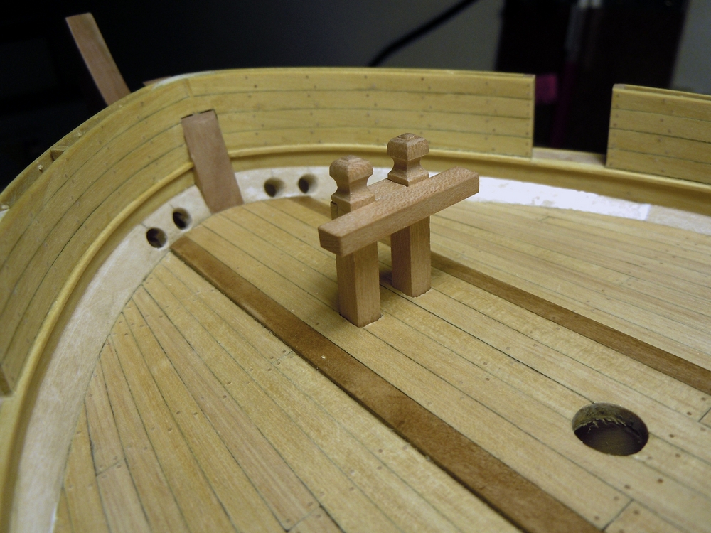
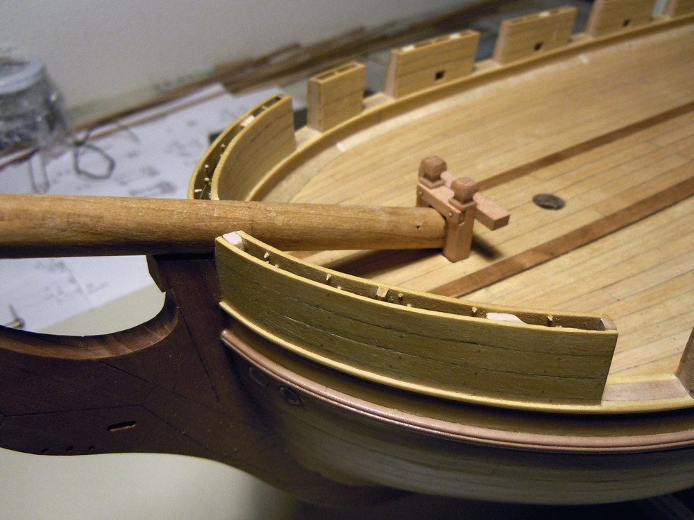
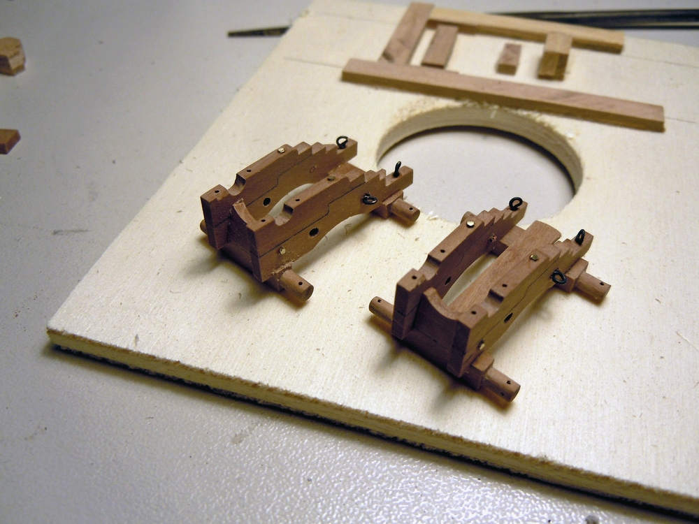
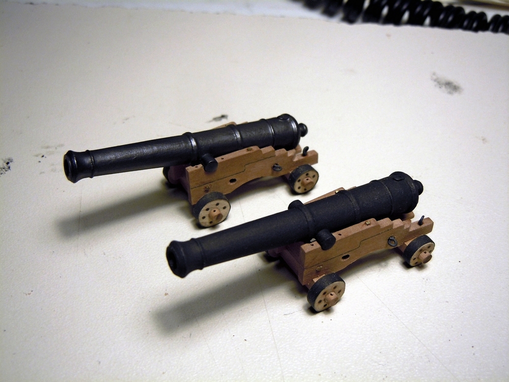
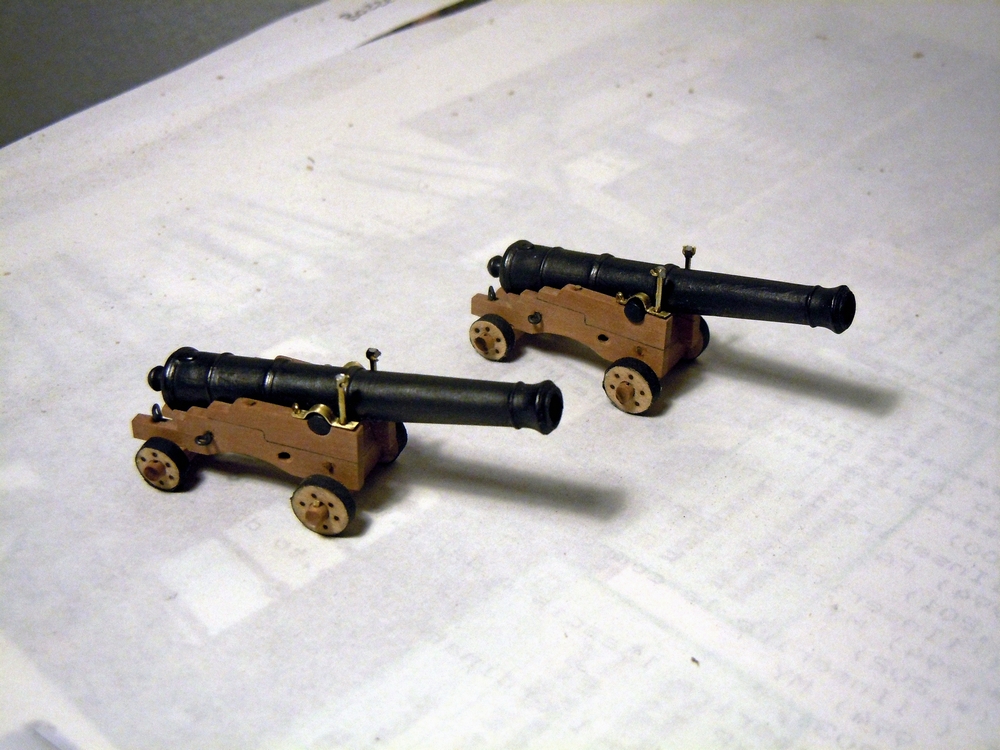
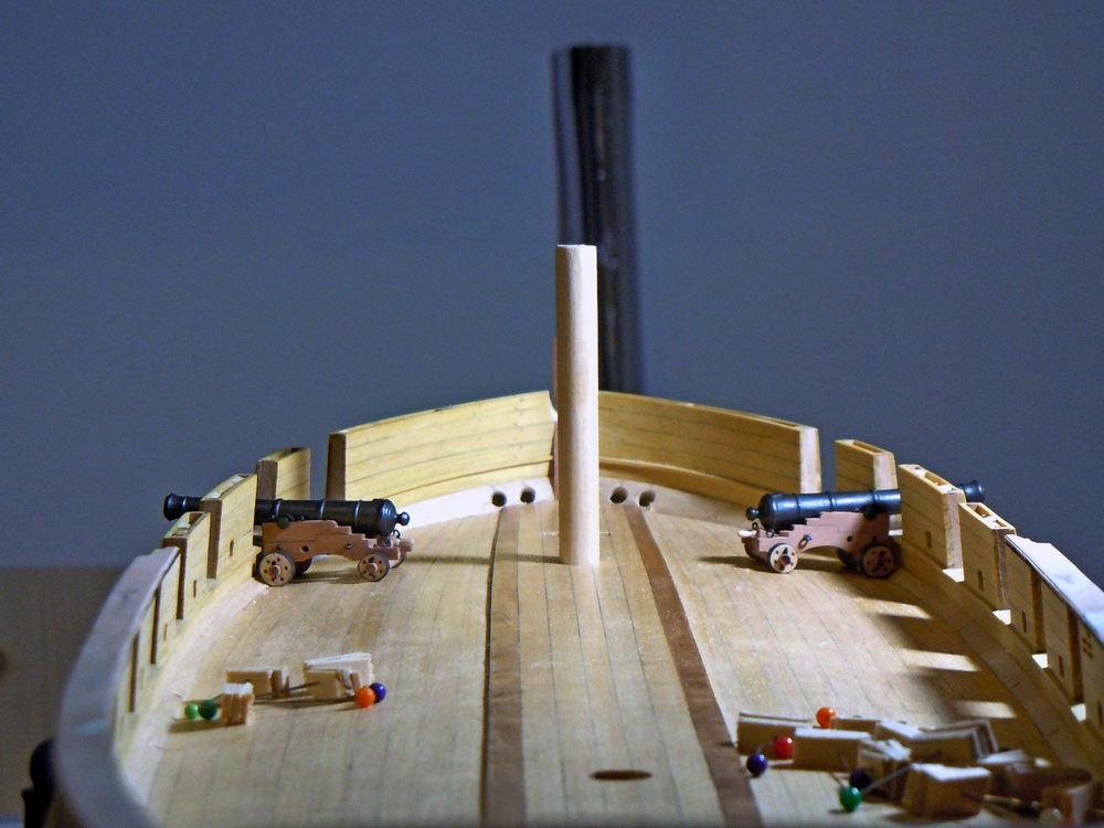
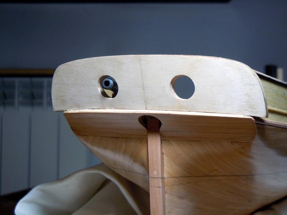
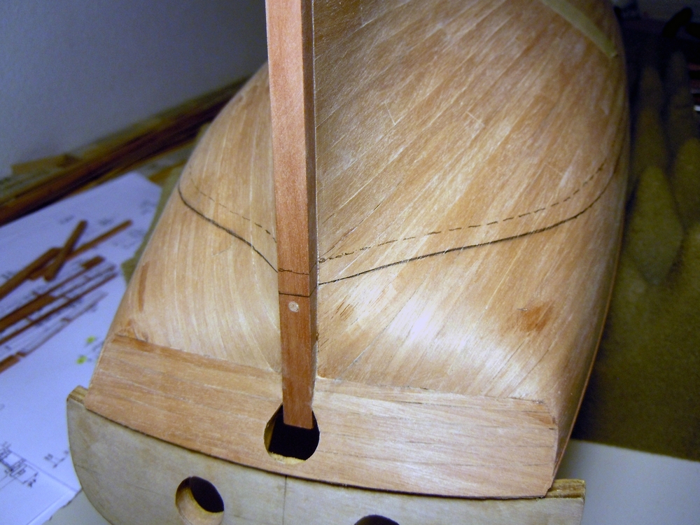
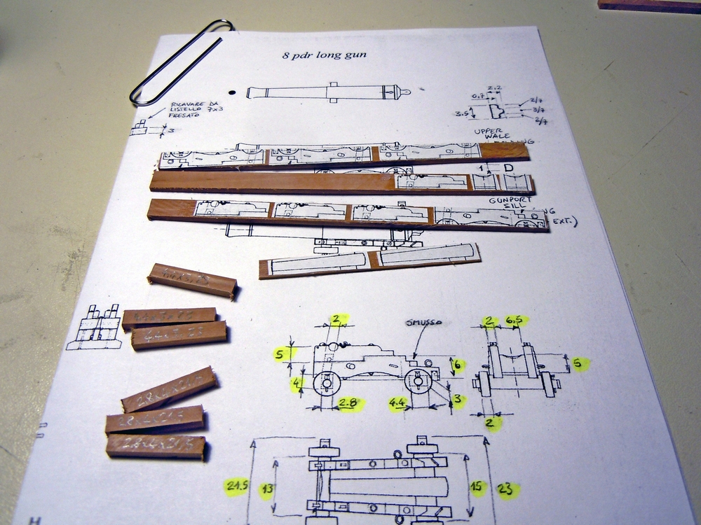
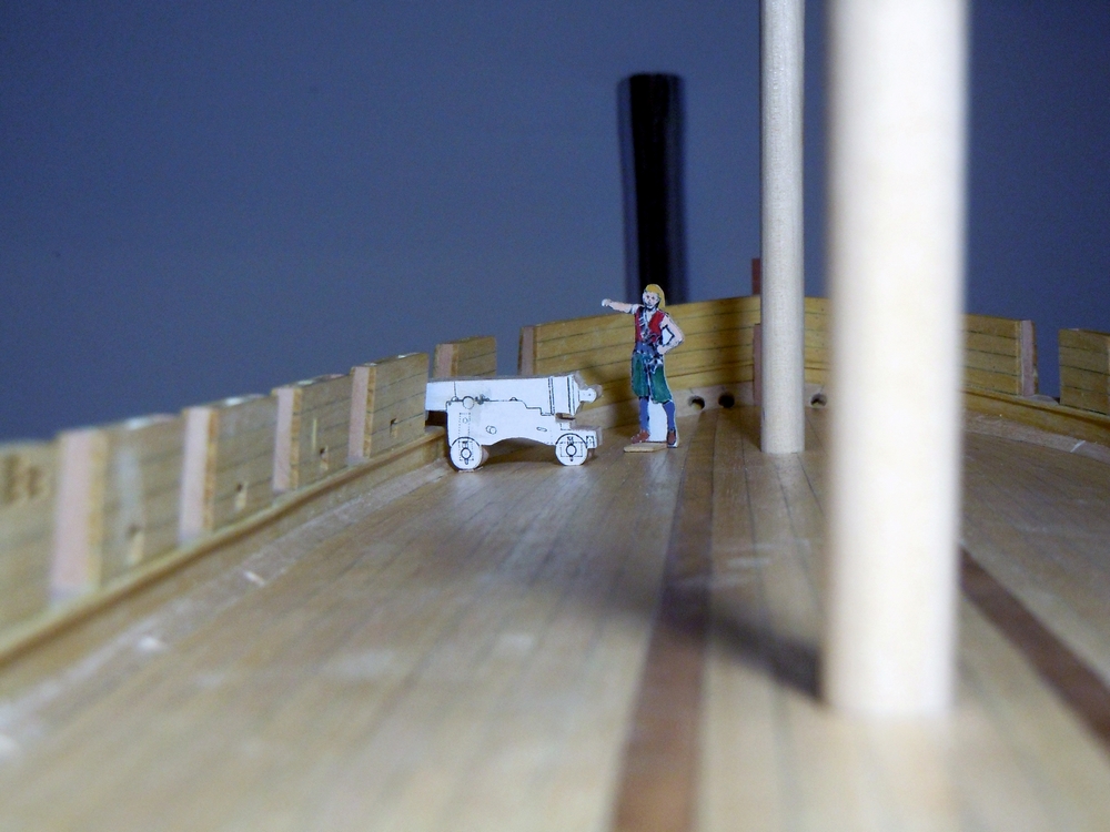
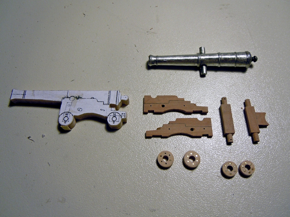
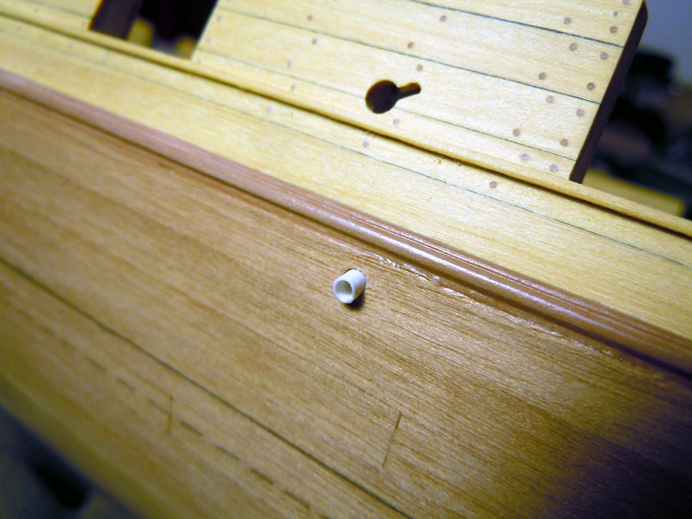
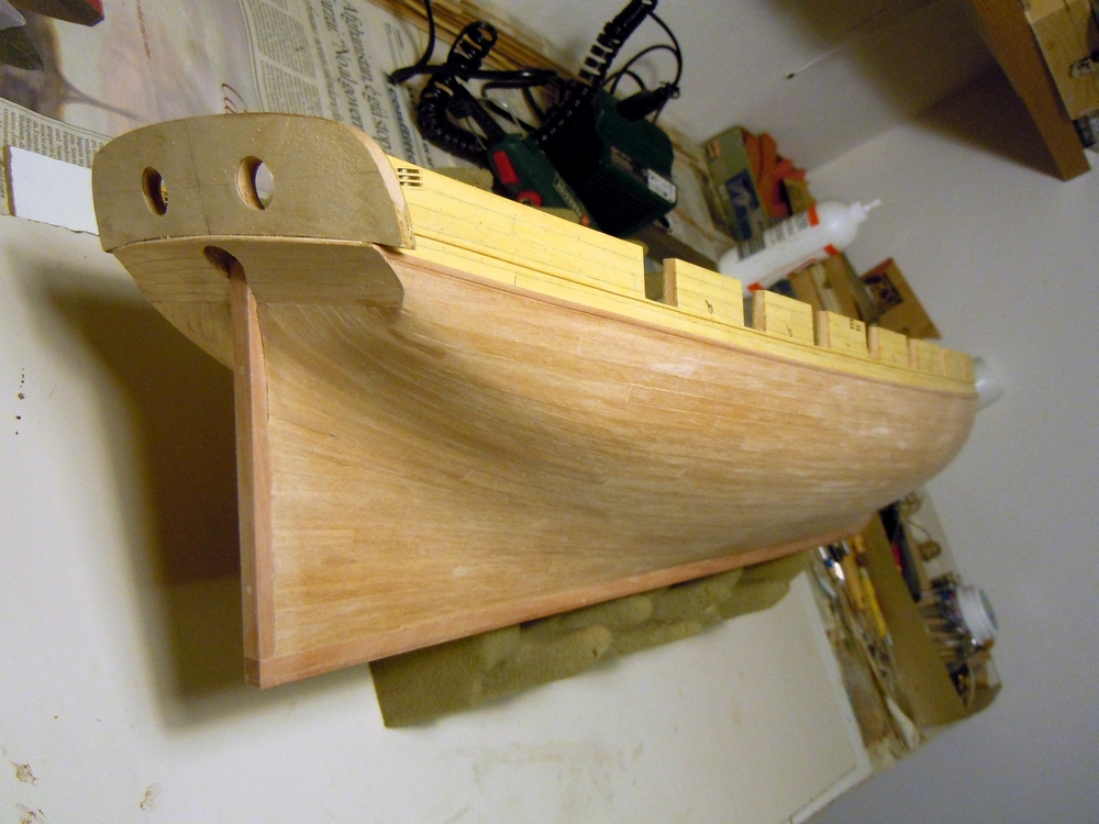
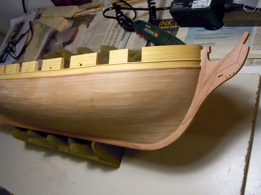
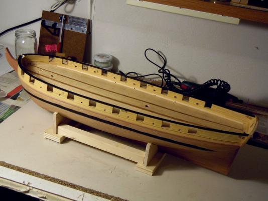
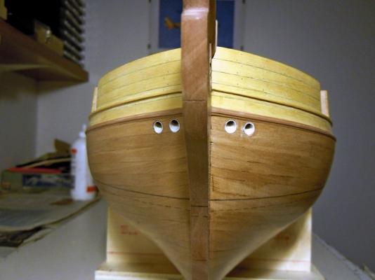
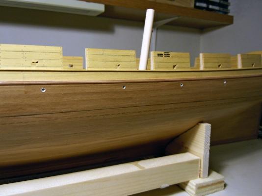
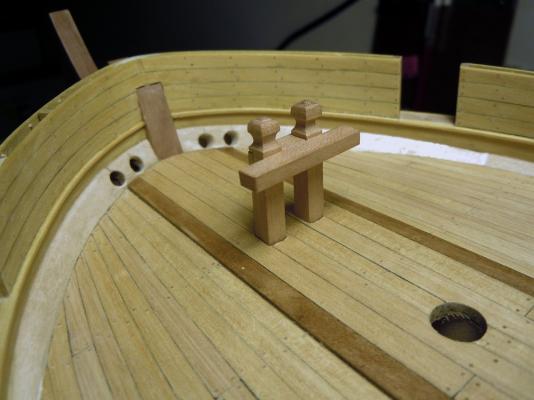
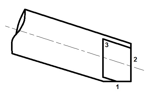
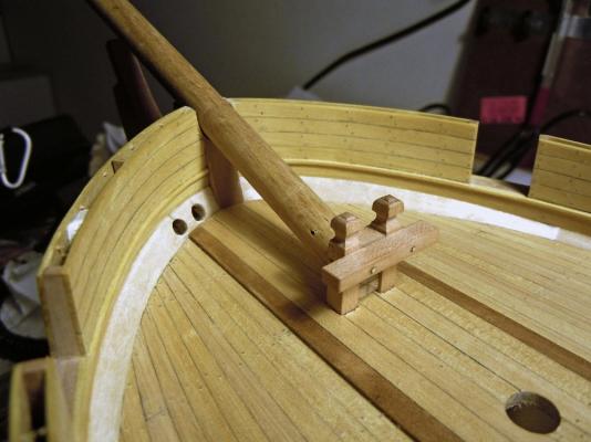
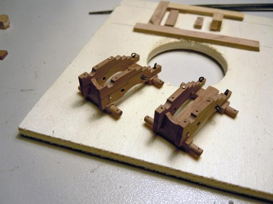
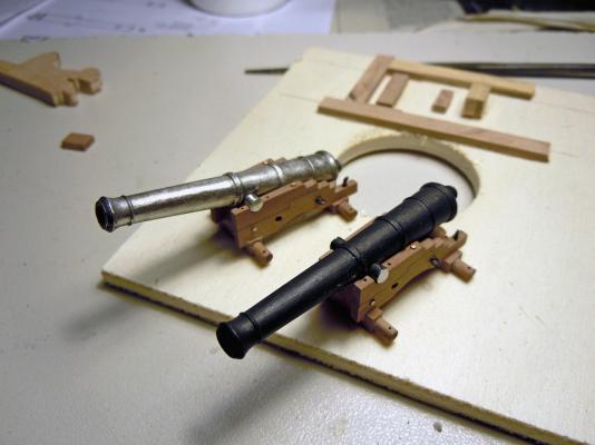
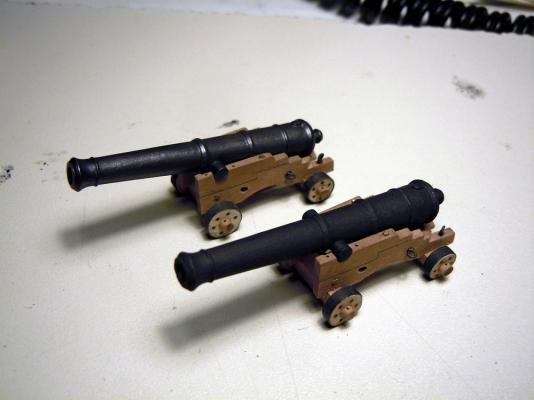
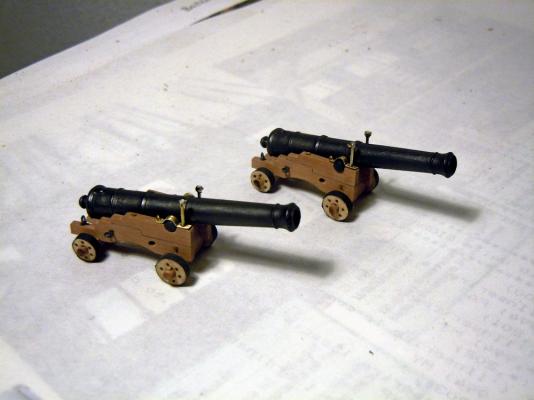
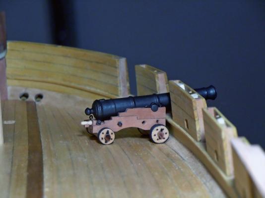
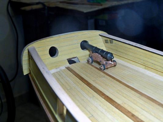
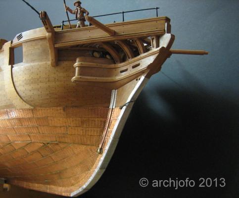
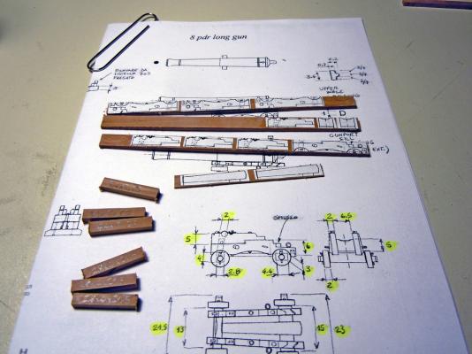
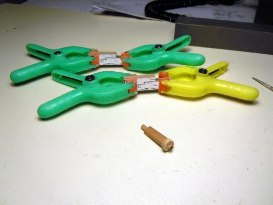
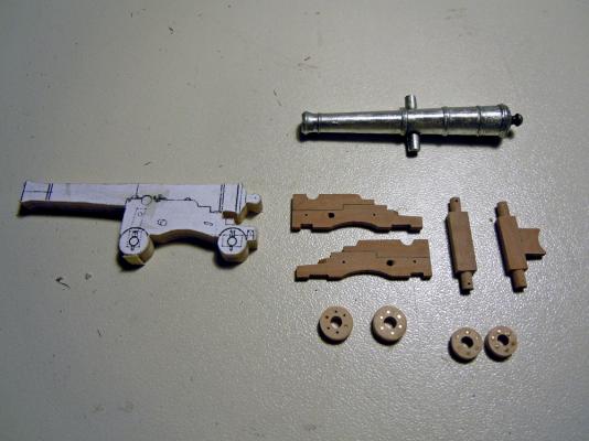
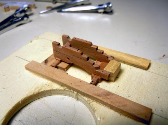
November 24th, 2015 Hi all while playing with the copper, at the same time I’m proceeding with the preparatory steps that I’ve described above. Hawse holes and water scuppers lining Both these jobs are now completed with the method I’ve described in the previous posts: in the end I didn’t try with the brass tubes because the result I’ve got with simple paper is fully satisfactory for me. Here are a couple of shots (still not painted): Bowsprit housing Every preparatory job has...a preparatory job to be completed before! So before building and installing the gunwales, I had to clear the housing for the bowsprit mast in the bow portion of the bulwark... but before being ready to do this task, I had to build the large bitt housing the foot of the bowsprit (btw, what’s its name?). I used Cherry wood for it, and just followed the drawings in the Ancre monography. I left the two legs longer than needed, then cut two square holes in the deck planks to house the legs. The holes are as deep as the deck planks thickness, so the bowsprit bitt is fixed directly to the false deck plywood. The final height of the legs is then adjusted so to have the correct distance between the deck and the horizontal beams of the bitt. Then, after adding a couple of brass pins to the center of the bitt legs, the bitt was positioned into its location. No glue for now, but the fit is so tight that it is not really needed while I’m checking the bowsprit position. The next pic shows the bitt before shortening the legs. To carve the bowsprit housing I firstly prepared a dummy of the mast, using a 10mm diameter dowel. First step was to measure the slope of the mast from the plans, with respect to the deck surface, which is about 19.5 degrees. Then I cut three faces into the foot of the dummy: first was a sloped surface (1) to match the deck: the easier way to do this is to use the disk sander with the tilting table set to 19.5deg. Then I had to sand the foot of the dowel at 19.5deg from the dowel section (2), so that it remains vertical w.r.t. the deck. Again, with the disk sander help... Third I cut two flat and parallel surfaces on the sides of the bowsprit foot (3), so that its width is exactly the same as the distance between the bitt legs. After these steps were done, I started cutting the bulwark above the bow timbers: initially with 10mm width, the same as the bowsprit diameter, then progressively narrower until obtaining a ‘U’ shape sloping inward. In the end, the external and internal pieces of the bow timbers were joined in a continuous saddle for the mast. While slowly removing material from the bulwark, the bitt provided a stable stop to the mast foot and at the same time a reference for its slope. A third check point was the distance between the dummy mast and the top of the bow timber, where the figurehead will be attached (sorry, don't know the correct name of this part): 9pdr guns Continuing with the 9pdr guns, I verified that the carriage cheeks were about 1mm too narrow for the gun barrel ... actually, it is the opposite, because the carriage is perfectly matching the plans. So, some deconstruction time also for me: I disassembled the cheeks from the axles and forward piece, built a new forward piece 1mm wider and reassembled the 5 pieces. The following picture shows the new wider carriage (left) compared to the original. The next shows how the second barrel (still bare) sits comfortably between the cheeks and is able to be trained upward without interference. The following picture shows both the carriages rebuilt, with all the bolts and ringbolts required and with the wheels completed by their iron bands. Next is a shot showing the two barrels painted: the first still with matt finish, the farther also polished with a nylon rotative brush and with some graphite powder from a 2B lead pencil. Final steps were to build the brass strips fixing the barrel trunnions to the carriage. They are cut from brass 0.5mm thick sheet, bent to match the trunnion, drilled with two holes and fixed by a 0.5mm brass hook (to the rear) and a 0.8mm pin (to the front). Finally, several shots showing the completed guns on the deck, occupying their position at the first gunports. The barrel is now correctly aiming upward, even though the elevation quoin is still not in its final position. The above closer picture shows the elevation quoin, with the pin handle lathed from a Birch toothpick, and the brass pins through the wheels axles. All the metal parts have been chemically blackened. Finally, I also tried to position the guns at the stern chase gunports ... again satisfactory !! To be continued... Fam


-
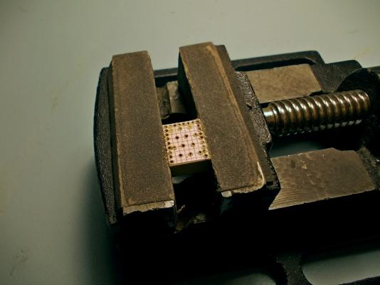
Hi guys I really appreciate all your contributions, now I have some less doubts about how to continue. Thanks to all the above information, I think we can recap that: coppering from stern to stem is confirmed to be applicable also to French ships (all contributors) coppering from waterway downward to keel is not wrong for a French ship of about 1810 (Gaetan), but also for a British merchant ships (Druxey, Jim Lad) coppering method varies from ship tp ship within the same navy and seem to depend by period (mtaylor) coppering downward from waterline is more difficult than the opposite (Gaetan) Unfortunately I don’t have access to the monography by Jean Boudriot to read about the method, and was unable to find anything in MSW explaining, or showing, the up-to-down process. I’ve only found these pictures (sorry, I’ve not asked permission to the owners, no problem to remove them immediatly): Vaiseau de 74 guns (posted by Gaetan Bordeleau) Other detail shots of this ship (see in Gaetan’s buildlog of ‘Le Fleuron’) show that it was coppered the standard way. La Crèole corvette 1827 (posted by Johann-Archjofo) Thise are clearly showing the up-to-down method, with 4 copper lines parallel to the waterline, but the coppering phase pictures was not posted by Johann. I think that what Gaetan is meaning is about the transition between the parallel lines of plates (I’ve just one in the Brick) and the upward bending following lines: at a certain point away from midship they start to bend up, so that the plates have to be cut where they overlap the parallel lines. The upward bend is very shallow at midship and becomes much more evident at poop and bow: whereas the latter is easier to see (and to do!), the former is more difficult ... and of course I don’t have any single picture of this area!!!! In the meanwhile, these are my first attempts to make the copper plates. I’m using the method by Dirk (Dubz): It’s working quite well, and it’s also fast... after the stamp is produced! The wooden stamp is Yellowheart (boxwood) which is quite hard and dense; the pins are made of steel, come from a dressmaker supply and are glued with CA into slightly smaller holes. My only concern is about the pins sinking deeper and deeper into the wooden support as a consequence of so many hammer hittings...will see! Stay tuned Fam


-
I fear I've hit a wasps nest!!! Thank you very much, firstly, to all of you guys, druxey and mtaylor and JimLad, I really appreciate I always thougth there was only one general rule, spread all over the world... of course it was a sin of ingenuity! Even in the British world the rule was not always observed, as the Edwin Fox seems to show. But probably in the French shipyards there was only the rule of the shipwright, changing from a shipyard to another. I mean: there is no rationale, I think, in starting coppering from the waterline downward or from the keel upward, neither for new ship building nor for ships hull maintenance. I've access to very few historic sources, but those that you guys checked are not showing a clear rule: maybe there is a 'Shipyard Rule', who knows? Should this be the method I've to follow... I'm not documented at all on it: I only know the opposite one unfortunatly. Do I have to lay the waterline strake first? Or do I have to start with the line of plates just below the waterline and then finish laying the waterline plates? And of course I've to start from stern and lay the plates going forward, but at a certain point they will start to taper: how do I calculate the correct tapering? In other words: is there any step-by-step example here in MSW to read and learn? Thank you very much for your support Bye Fam
-
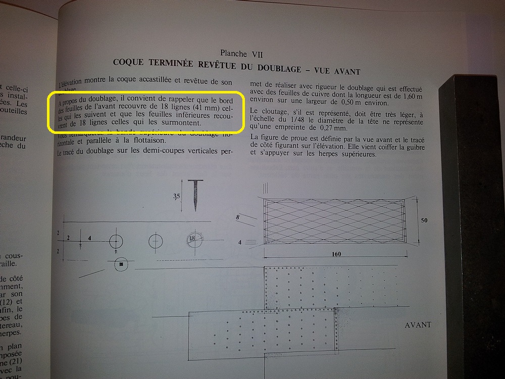
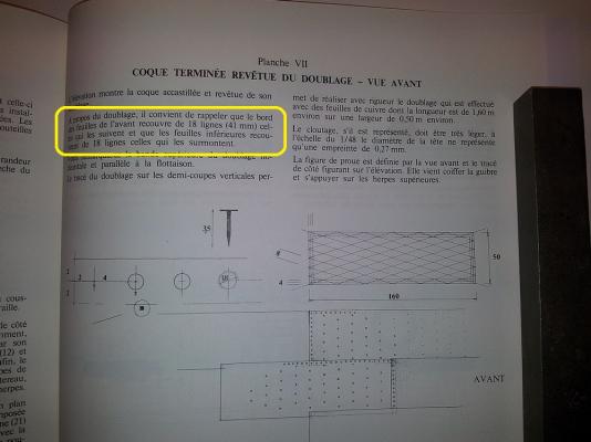
Hi all, I have a question about copper sheating, can anyone give me some clarification? The following is a shot of page 67 of the Ancre monography, dealing with copper sheating. There is a sentence, explaining the overlays of the copper planks, that is opposite to my knowledge: I'll translate from French for you: "...as far as sheating, it's worth to recall that the edge of the forward sheets overlays by 18 lines (41mm) the edge of the following (meaning 'backward') sheets and that the edge of the lower sheets overlays by 18 lines the edge of the upper sheets...". The attached sketches seem to confirm this sentence. The first part is ok, but shouldn't the second overlay be the opposite? I mean, if I start coppering from the keel upward and from stern to stem, the overlay is automatically: - forward overlays backward - upper overlays lower Can anybody explain me where is my understanding error? Thank you so much in advance and bye Fam
-
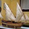
Very beautiful ship! I've built the Dusek Knarr in 1:72 scale, a pleasent side-project completed in 4 months (at my usual slow pace...) Have a nice building Fam
- 170 replies
-
- 2
-

-
- gokstad
- dusek ship kits
- (and 1 more)
-
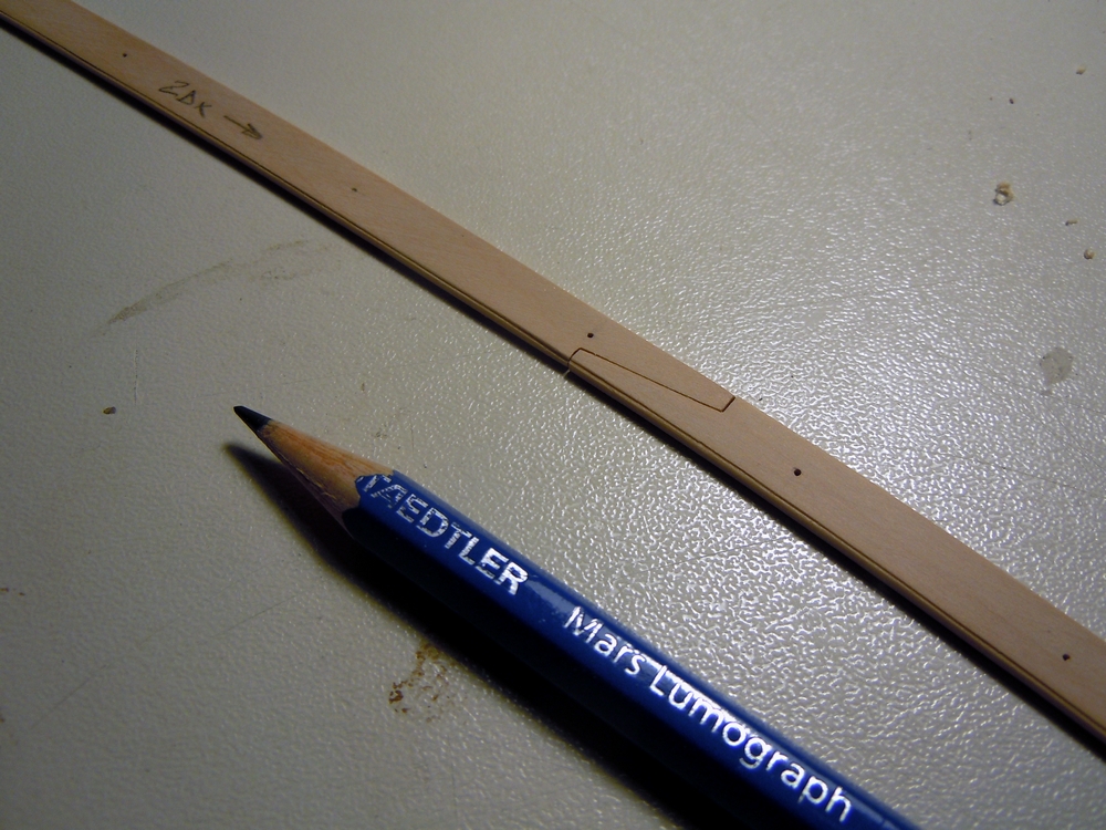
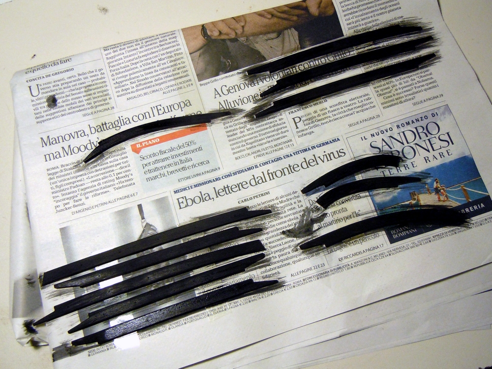
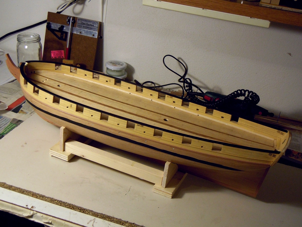
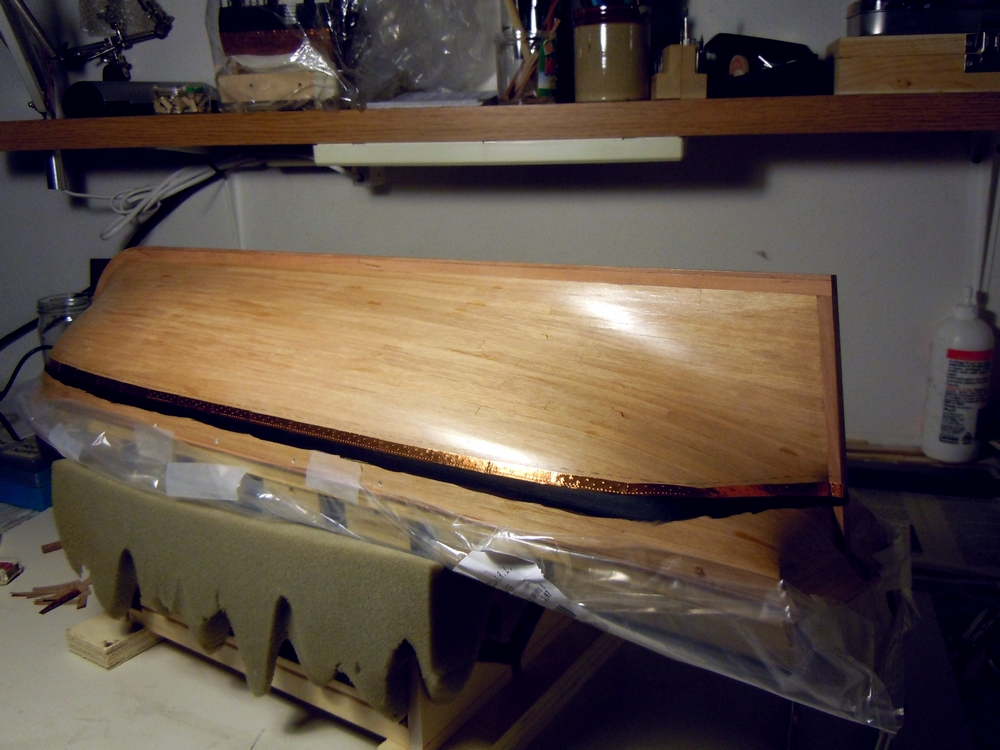
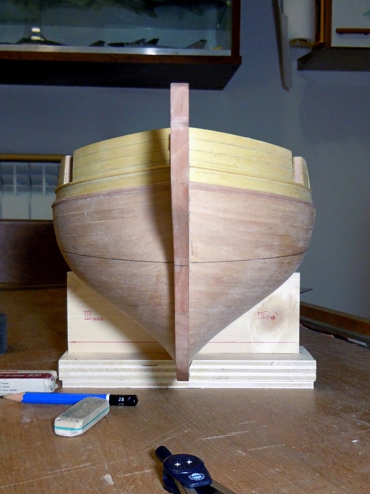
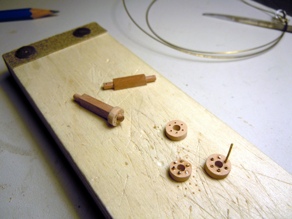
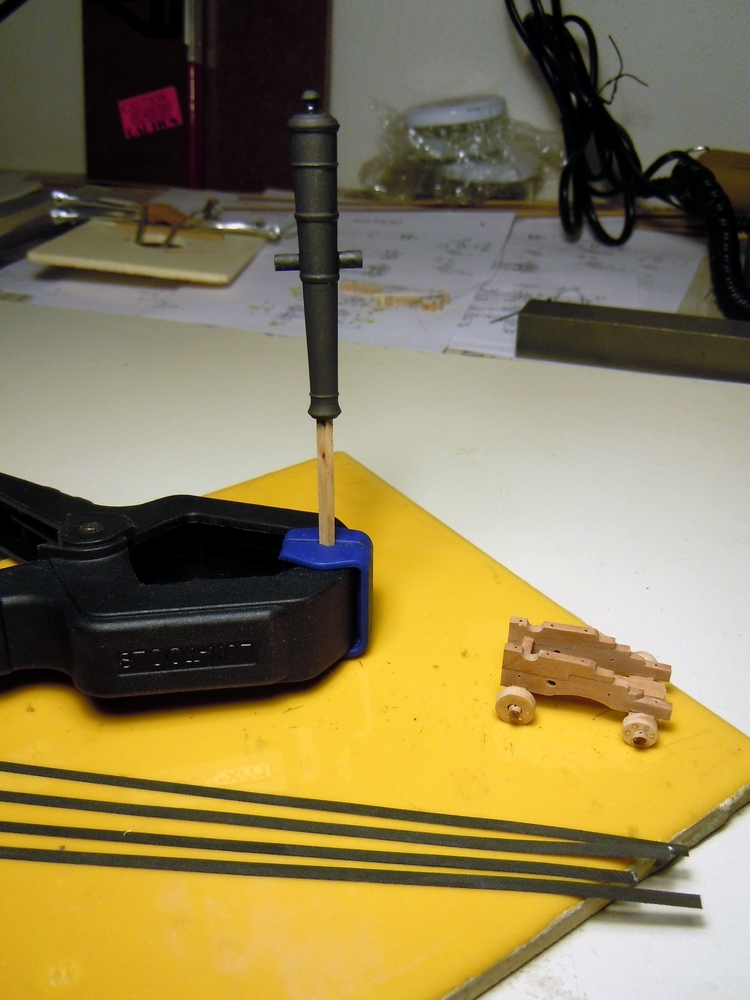
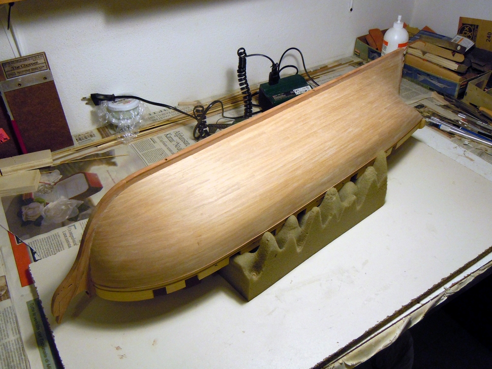
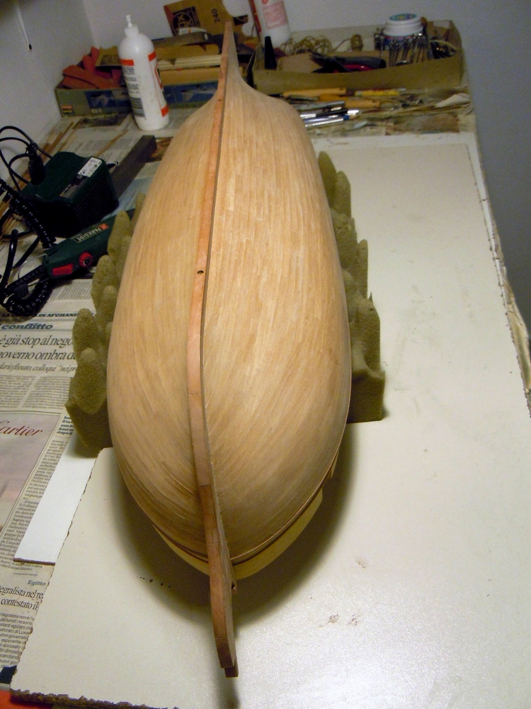
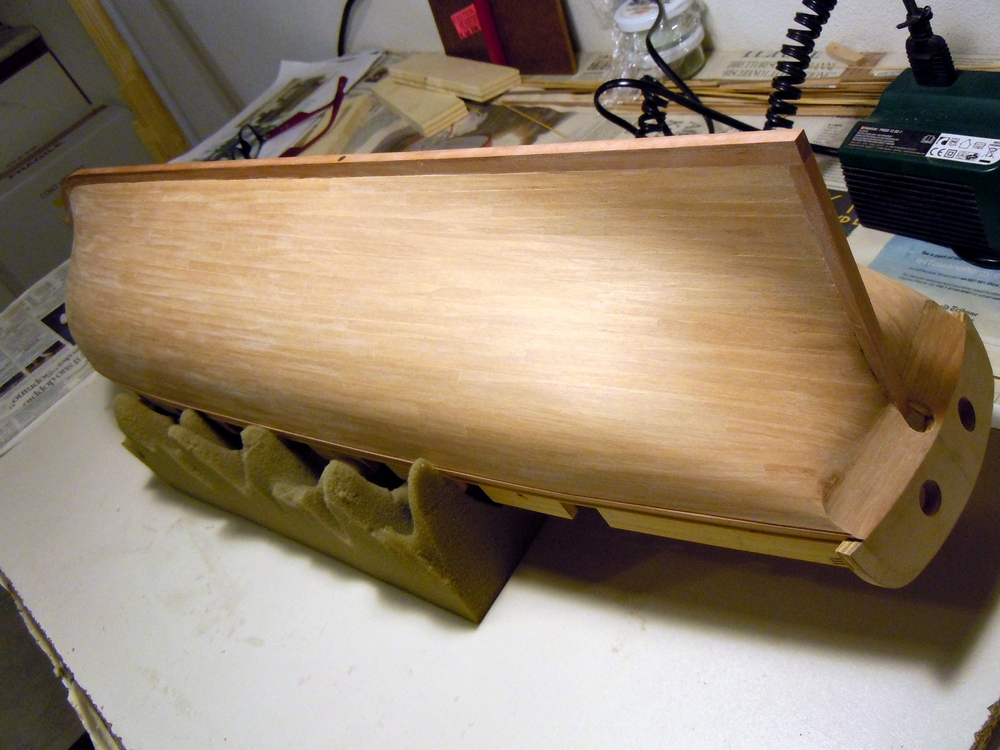
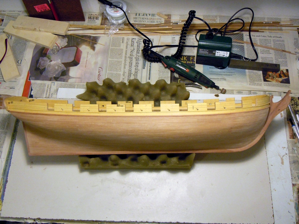
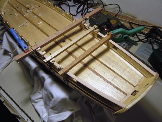
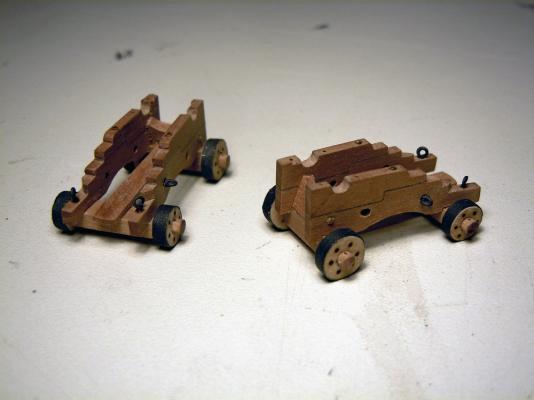
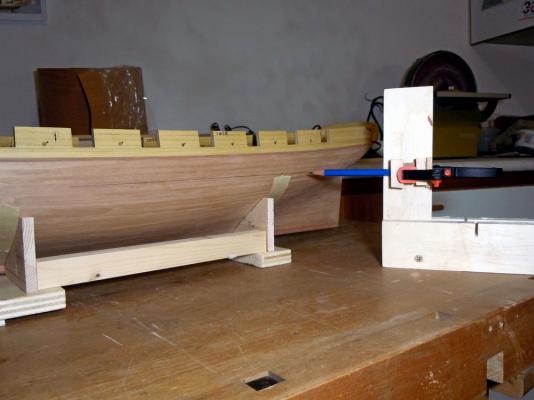
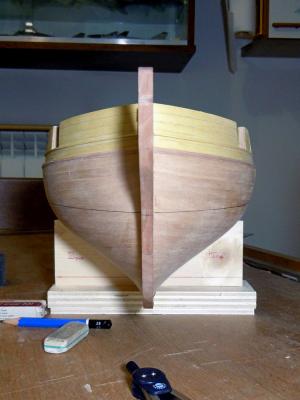
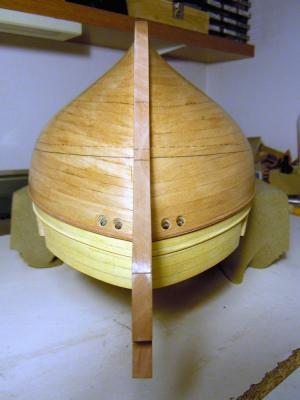
November 10th, 2015 Hi all the first steps forward in the above scheduling, plus some extras... I decided to draw the waterline as first step, as the following coats of sealer would have protected the WL from the following sandings. This was another “First Time” for me, as I never had the need to do this job in my previous models. So I built two simple jigs: the first to firmly hold a 2B type lead pencil at the required height, while at the same time providing an ample and smooth contact surface easily slipping on my workbench plan. The second was to hold the hull so that the waterline was perfectly parallel to the workbench surface. This was built in two steps: transverse axis setup and longitudinal axis setup. For the transverse (athwart) axis I used the hull profiles at bulwark VI(aft) and III(fwd) from Ancre plans, glued to a couple of 20x40x200mm plywood scrap pieces. I then laid a bubble-level across the main deck, from port waterway to stbd waterway, and adjusted the two supports profiles until the deck was horizontal at quarterdeck, midship and forecastle. On the longitudinal axis, I measured on the plans the vertical distance from the WL downward to the bottom of the keel (false-keel, indeed) at two extreme bulkheads: I found a difference of 8.5mm from bulwark XIII(aft), where the keel deepest point is located, and bulwark V(fwd). So I had to raise the keel w.r.t. the workbench surface such that bulwark V(fwd) was higher by 8.5mm above the table surface than bulwark XIII(aft). This was done by adding wood wedges of increasing thickness under the forward support, until I got the required height difference. After these alignment steps, I connected the two supports by gluing two battens, so to lock their relative positions, and the hull support jig was completed. Drawing the waterline was just a matter of measuring and then working slowly and accurately, in short line pieces, connected one after the other. The height of the WL was measured and marked downward from the sills of three gunports (again forecastle, midship and quarterdeck), then I double-checked with another set of measurements downward from the large molding. The 6 measures matched quite well, and they were at constant height above the table in all three control stations. Then repeated on the other side of the hull. The trickiest drawing point was at stern, where the hull sloped shape tends to push the pencil tip down... I had to try a couple of times before finding the correct pressure to apply to the pencil. A couple of shots of the waterline completed. Next I draw a dashed line at 5mm constant distance down from the WL: this is the lower edge of the first band of copper plates, which is laid just across the WL. Then I started applying several coats of wood sanding sealer, with intermediate sanding by progressively finer sandpaper. You can see several darker spots in above picture: I had to use some CA glue to fix the 2nd layer planks where, in some points, was not glued correctly. Not a problem at all here, as the hull will be coppered and painted, but I must always keep it in mind if I want to build the hull with the wood natural color.... another lesson learned for the second planking phase! In between a coat, sanding, another coat... I wanted to start something different as a distraction side project. I’ve received from The Lumberyard three gun barrels (18pdr long gun, pewter, 1/4 inch scale) that almost perfectly match the size and shape of the 9pdr long guns of my ‘Brik de 24’. So started to build the gun carriages. Wood type is pear of the darker shade, the same as for the keel and bow timbers. Below you can see that I divided the cheeks in two pieces, a la françoise, with a step joint in the middle. So glued the templates to the 2mm thick billets using stick glue, easily removable. The other pieces are for the wheels axle. The Ancre plans show the carriage with wheels of the same size, 7mm diameter, but I was not convinced about this because the curved shape of the deck usually needs to be compensated by larger wheels in front and smaller in the back. A quick check with a prototype confirmed my doubts: the gun barrel, horizontal w.r.t. the carriage, was aiming downward. So I filed the bottom of the rear wheel, and glued a batten below the front wheel... much better this time, the barrel was almost horizontal: So decided for slightly modified wheel sizes, larger in front and smaller in the rear: 7.6(ish)mm and 6.3(ish)mm respectively. Here below the two cheek couples are glued together to ease shaping and drilling the required details, while the wheels and axles are being prepared. Here are all the carriage pieces ready for final assembly (the brass pins in the wheels will be later blackened): Assembly jig: I improved the visibility of the joints between the two pieces of the cheeks by using a lead 2B pencil, same method as for deck planking. All the holes you see are just 0.6mm pilot holes, to locate the positions of the various details. The larger 2mm holes in the cheek sides are for the recoil breech, which passes through the carriage in the typical French fashion of beginning 19th century. The support sledge for the elevation wedge is still missing. The barrel then: I was not able to find in internet a reliable method to chemically blacken pewter, nothing similar to the effect that can be obtained on brass. So decided to give paint a try: Humbrol n.53 Gun Metal enamel (for plastic modeling) as a color base, plus about 40% of matt Black for a darker shade. The mix was applied after cleaning the barrel from the casting signs and after a deep wash and degreasing of the barrel. Here is the result with the first coat: It’s still a bit too matt for my taste; it’s missing that “metallic shine” that I was looking for. But I’ve already experienced with the carronades for my USS Constitution that this paint can be polished using a rotary nylon brush: I’ll show you the final effect as soon as the job is done also for the second gun. The paper strips painted with the same color are for wheels iron banding. Back to the hull: before giving the last sealer coat I drilled the water scuppers and the hawse holes. In the second picture is also apparent the shade of color of Tanganyika veneer after 3 coats of sanding sealer. Last picture shows the first real trial of lining the water scuppers. I’ve already explained before the method I’m testing, now I will try to use it to see how it looks. A 2.5mm hole is drilled with an upward slant, some standard printer paper is rolled and glued around a 1.75mm drill bit, the pipe is then just inserted into the hole for a dry fit. Have a nice day! Fam


-
Thank you Dirk for your prompt reply, you really did a good job and also a great explanation! I've juste copied all your posts dealing with coppering and will use them as a tutorial. I've just two questions, if you don't mind: - you trusted in the back adhesive of the copper strips...any reconsideration or change of mind after lot of manipulation of the hull? - can you provide the "recipe" for the salt-vinegar solution? I mean quantities, proportions... By chance, I also read your method for lining the water scuppers...I will consider it, if only I manage to find suitable brass tubes Thank you so much Fam
-
Hi all can anyone here address me (e.g. provide links) to some MSW buildlog where procedures-details-suggestions-comments are given about how to copper a hull? I'm also looking for suggestions about the type of glue to use, should I decide to improve the copper strips adhesivity. Thank you so much Fam
-
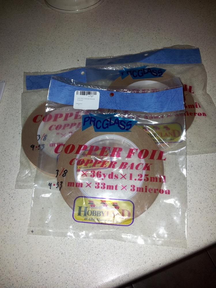
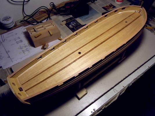
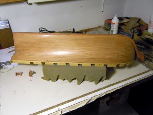
October 30th, 2015 Hi all it’s been a long time since my last update from the 'Brik de 24 dockyard'... I was definitely lazy in this period, but the truth is that I was really bored by this phase! Anyway, second planking layer is now completed. In the end I decided to continue with the spiling technique also on the starboard side. The following is the final result: the planks are barely visible on the stbd side, which I have already roughly sanded with 80 and 120 grit sandpaper. A bit better on port side of the hull, second picture. Next jobs will be to prepare the base for the copper sheeting. But before getting to this step, I have some other phases planned: continue sanding the Tanganyca planks, until I get a smooth finish. apply 2-3 coats of acrylic wood sealer, with other intermediate sanding. before applying the last sealer coat, I will also re-open the water scuppers and the hawse holes, and will line them with the method I’ve shown before (only on the outside, for now). draw the waterline, a task that needs preparing a dedicated jig then I’ll apply the first coat of black paint, from the gunport sills molding downward to the waterline. I’ve not yet decided if use an acrylic paint or a wood stain: I will test the efficacy of the stain on the Yellowheart wood, which has a very closed texture. preparation for coppering will end with opening the housing for the bowsprit mast in the forward bulwark (with the help of the bitts holding the mast foot to get the correct slope) and to fit the gunwale on top of the bulwarks. I’ve read all the discussions by my good friend JA about the materials and method to use for copper sheeting. I think I will give a try to this: With 9.53mm width it is pretty close to the 9.8mm width of the copper plates I measured on Ancre plans. The strips are self-adhesive, but I’m not sure whether trusting in the adhesive power characteristics (mainly in the long period) or gluing every plate with some type of glue... any suggestion from the forum members is really appreciated! Have a nice building day Fam


-
Really beautifully looking small boat, and unusual (but effective) building method! Again my congratulations Antanas!! Fam
- 13 replies
-
- 1
-
-
- 95mm boat
- master korabel
- (and 1 more)
-
Really beautifully looking small boat, and unusual (but effective) building method! Congratulations Fam
- 22 replies
-
- 1
-
-
- master korabel
- 75mm boat
- (and 1 more)
-
Outstanding building Antanas I've found your build log only today and have read everything with lot of interest. Definitely not an beginners-looking kit, mainly thanks to your improvements! Fam