HOLIDAY DONATION DRIVE - SUPPORT MSW - DO YOUR PART TO KEEP THIS GREAT FORUM GOING! (Only 36 donations so far out of 49,000 members - C'mon guys!)
×


Fam
-
Posts
185 -
Joined
-
Last visited
Content Type
Profiles
Forums
Gallery
Events
Everything posted by Fam
-
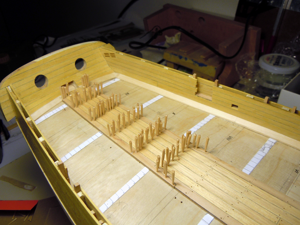
 Thank you all, I really appreciate! Treenailing... treenailing... I calculated something like 21x50 treenails for the entire deck... makes about 1000+ nails, not too much! 300 done, 700 to go but I'm now on a short visit to my parents-in-law, far from home, so shipyard is temporarily closed until Monday Cheers Fam
 -
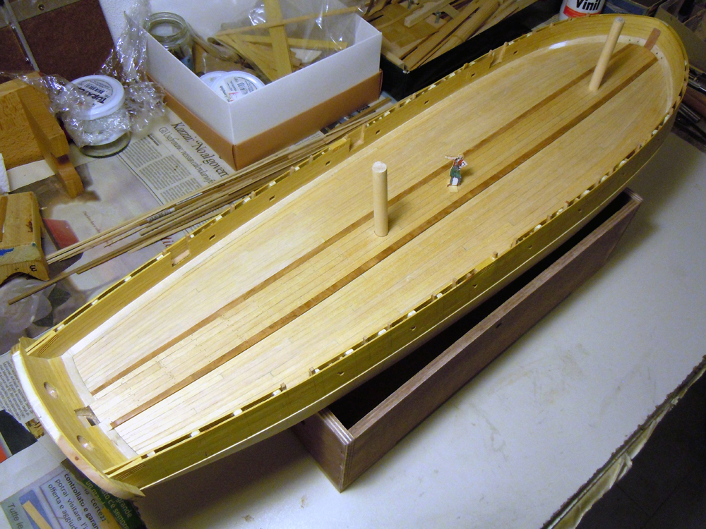
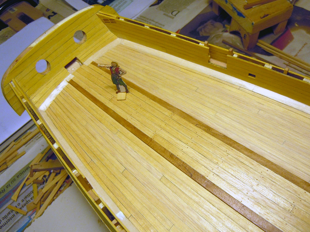
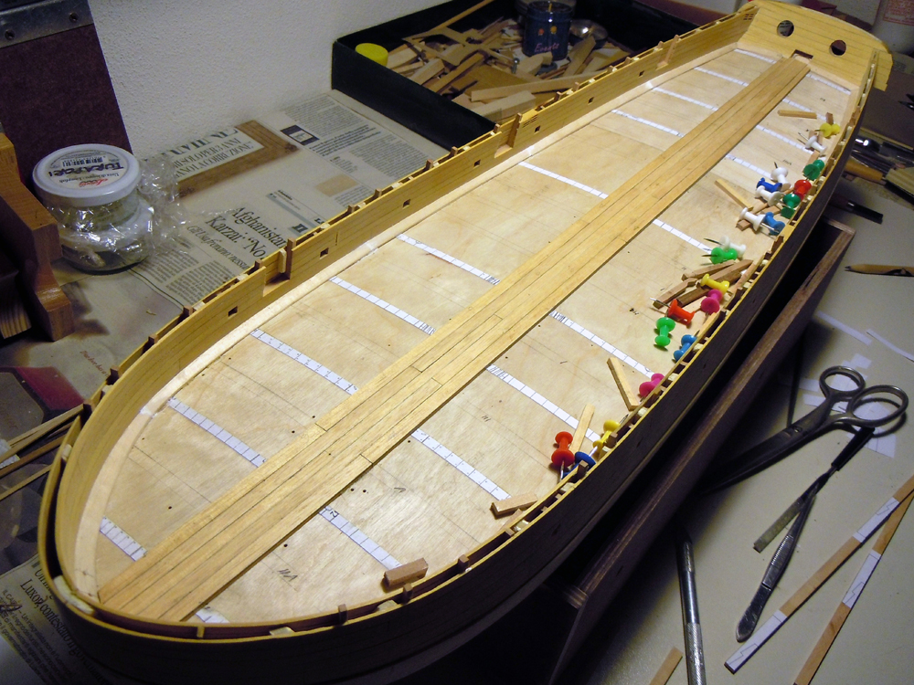
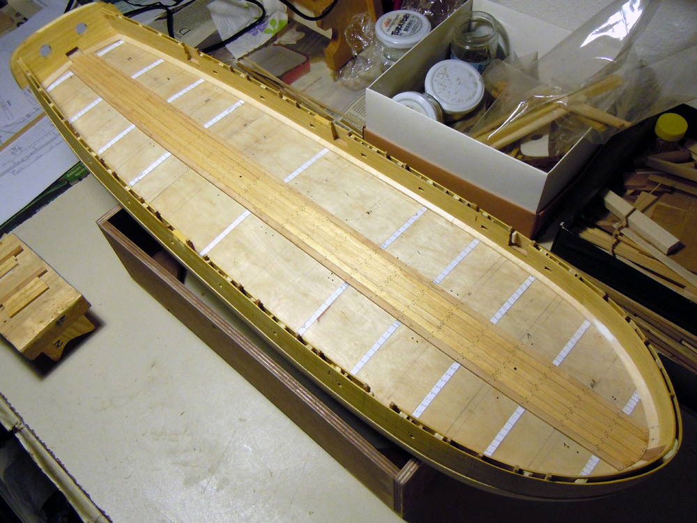
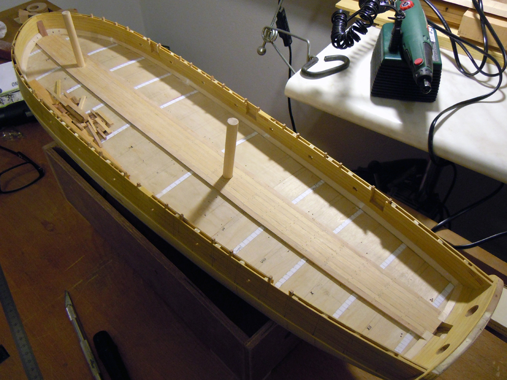
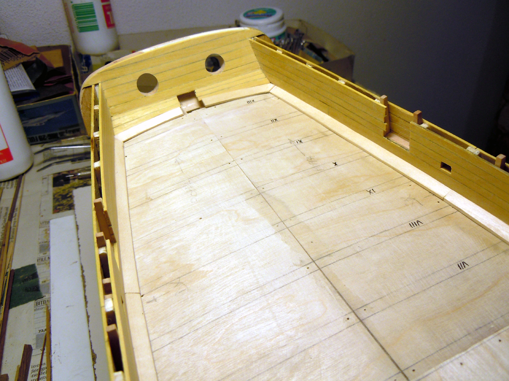
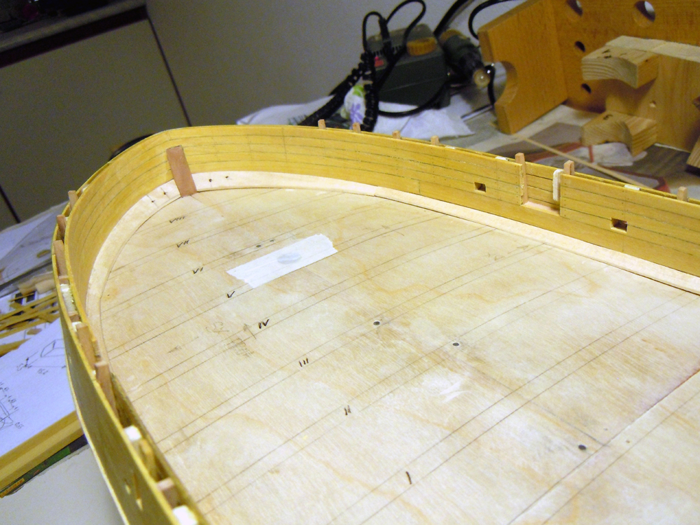
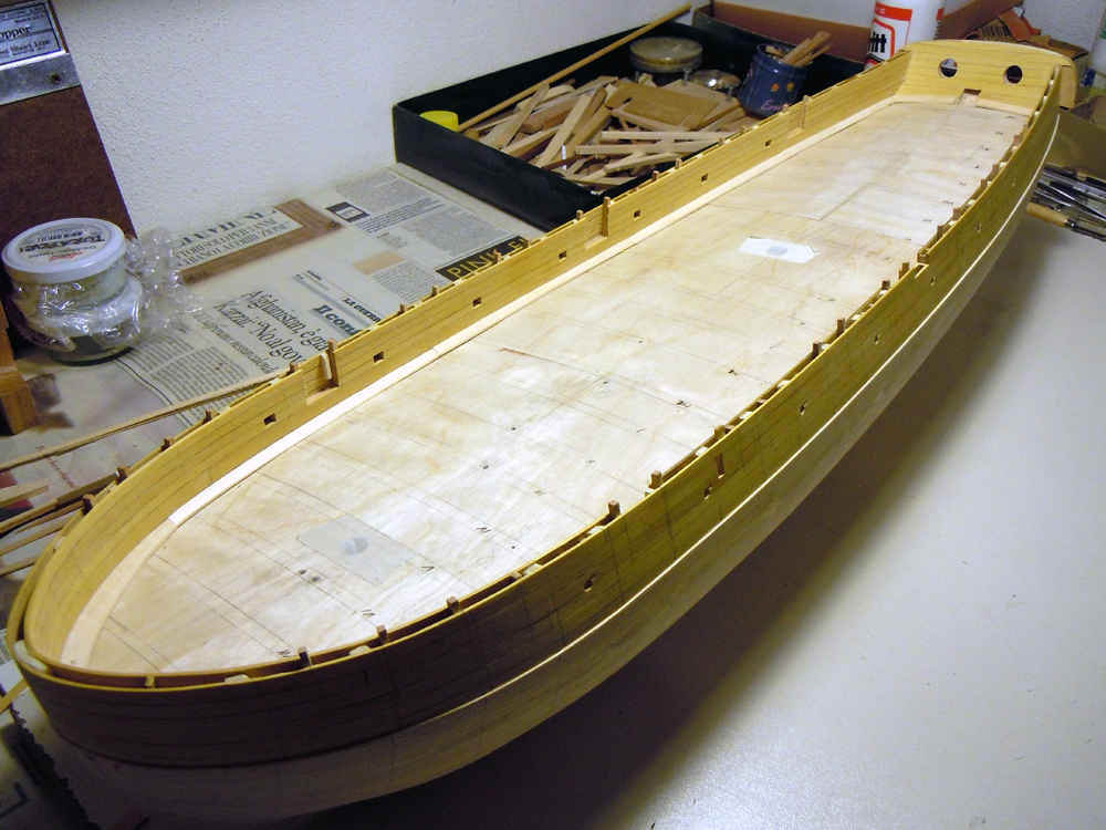
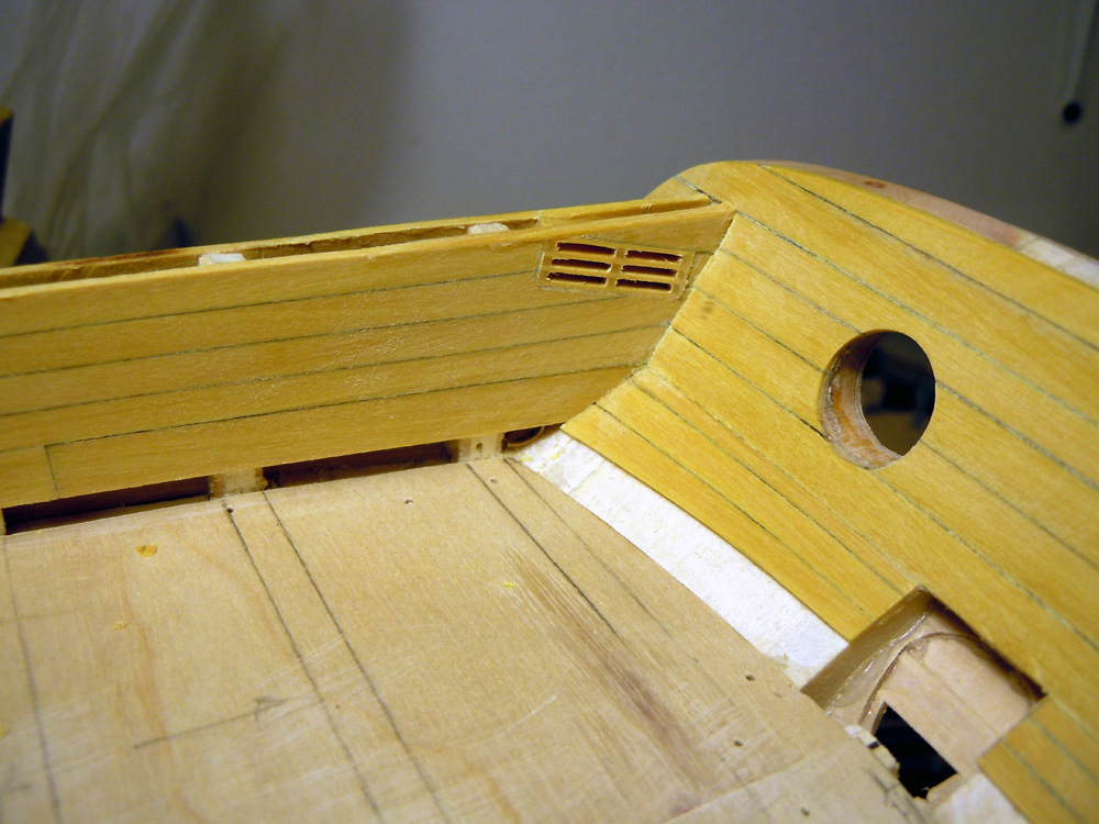
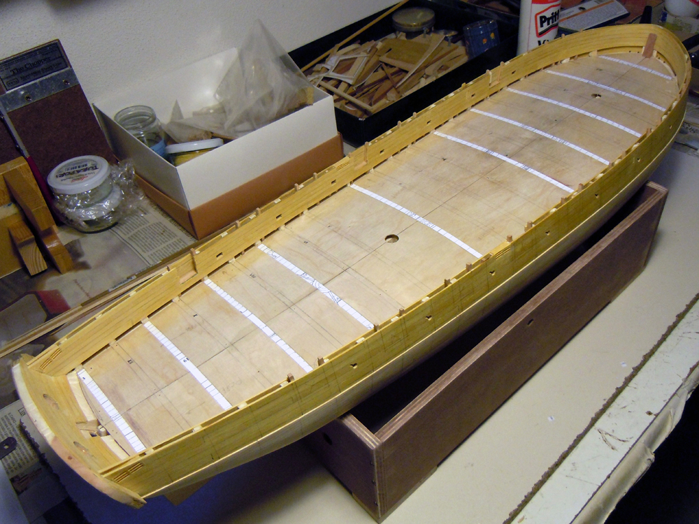
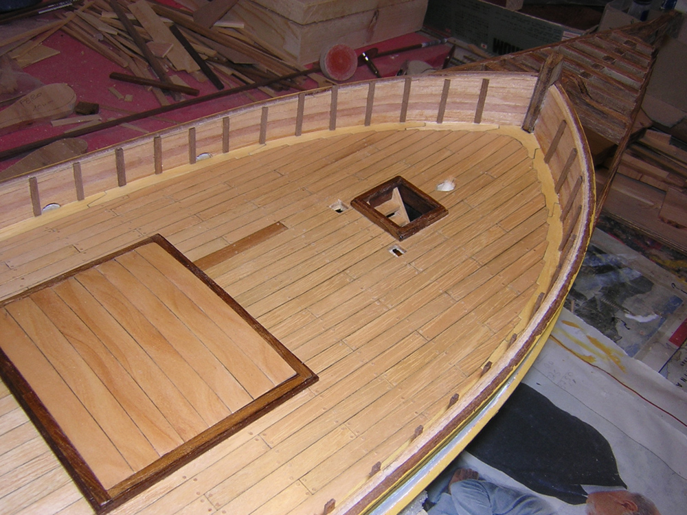
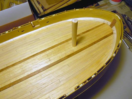
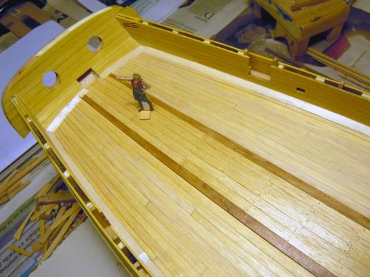
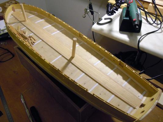
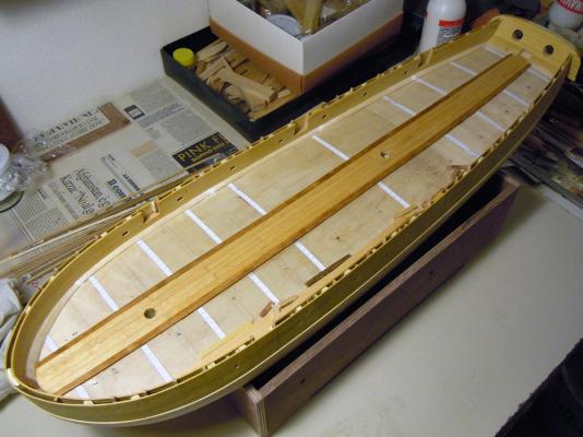
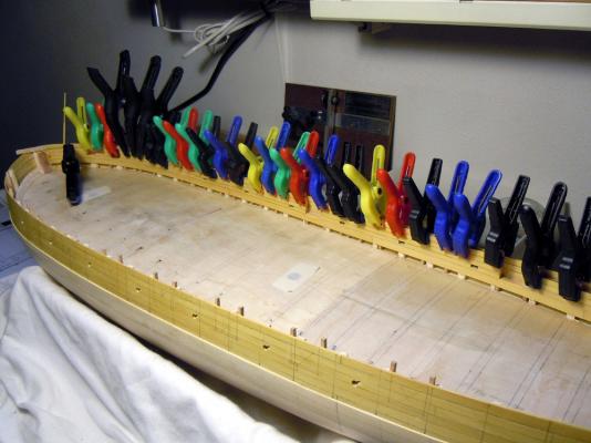
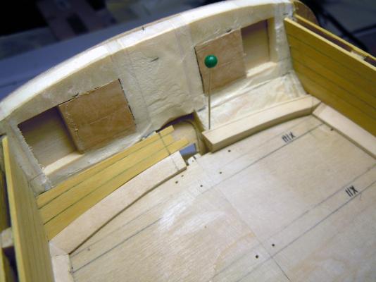
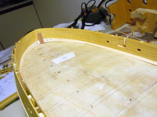
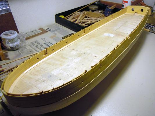
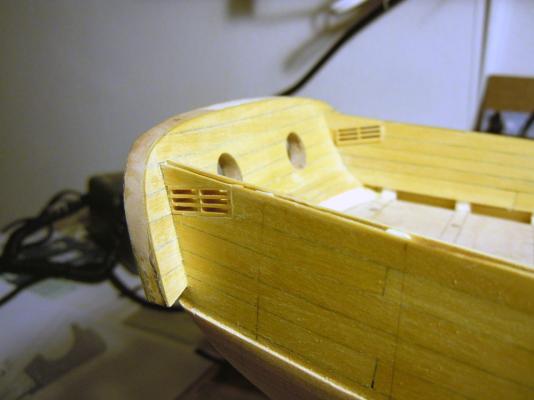
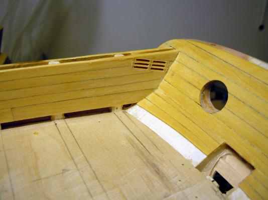
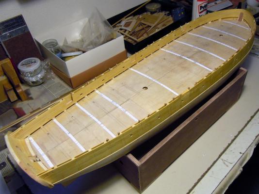
April 29th, 2015 Hi all A new small update from my shipyard of “Le Brick de 24”: I’ve finally completed the deck planking! The last lateral planks were really hard to set, because I had no more room to set wedges or to force them in position with any tool other than fingers ... aching fingers in the end!! Anyway, it’s done and I really like the way it come out. Here is a general bird-view... I’ve already started sanding the port side but the planking will be more visible only after application of a coat of sanding sealer. A shot of the forecastle area ... ... and another of the quarterdeck area... Now the planks curvature is evident, mainly at the bow. The forward-most and rearmost planks of the most external strakes have been spiled, because that amount of curvature was too difficult... well, to me, because I didn’t dare to try the extreme bending techniques shown by some other master shipwrights here in MSW Now the next jobs are: scraping/sanding the planks even tree-nailing the entire deck (already started yesterday to mark the holes locations) drilling the water scuppers in the waterways, only drilling the in-out pilot hole and finishing the scupper inner portion drilling the hawse holes, only finishing their inner portion applying a coat of sanding sealer to the deck planks I think this will take a couple of weeks, after which I can switch to the hull exterior to install the keel, the stem and the rudder post. Best regards Fam

-
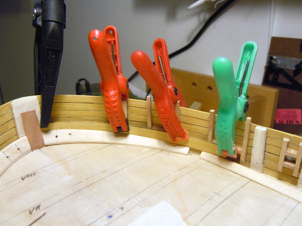
Hi Jack it's coming out so good that it is also ok if you in the end decide not to apply any coppersheating or paint!! Good job, also like the wood color! Fam PS.: good tip for the tool pressing the planks at the stern
-
April 24th, 2015 Works in progress ... I really love it, but it's not that easy The amount of taper and edge curvature is evident, and increases the further I go. Still 3 strakes to go, and have to use soak&heat method to bend the planks. Regards Fam

-
HMB Endeavour by mikec - Eaglemoss
Fam replied to mikec's topic in - Kit build logs for subjects built from 1751 - 1800
Mikec, if you start rigging from hole #1 in the top (e.g. to port), using a stopper knot at the end of the line and passing it from below the top to above the top, then go down to port side of hole #1 in the euphroe, up to hole #1 at starboard (passing from above to below the top), then go to hole #2 at starboard (passing below the top), then from above the top down to hole #2 of euphroe from starboard, etc... Would it work? Fam -
Many thanks for all the likes, I really appreciate! Deck planking is proceeding, but have to say that it takes longer than I expected because there is almost no plank that can be set and glued as it is: each plank needs several dry fitting, width adaptation along the bulkheads (for variable tapering), beveling, edge bending, caulking simulation... Curved planks are definitely not easy, the only advantage is that I can work with two planks at a time, as port and starboard are symmetric! Well, it is always like spiling the planks for the hulls. So in the end I need about 1.5 hours to prepare and set two complete strakes (P&S), then have to stop to let the glue set. Also have to admit that guidance provided by the paper strips glued athwarthship to the false deck is very useful, and I strongly suggest this method to whoever has to deal with curved deck planks. I've also decided to give up with use of joggled joints where planks meet the waterway at the bow, because the waterways will be painted black and the joints wil disappear... waste of time! Stay tuned Fam
-
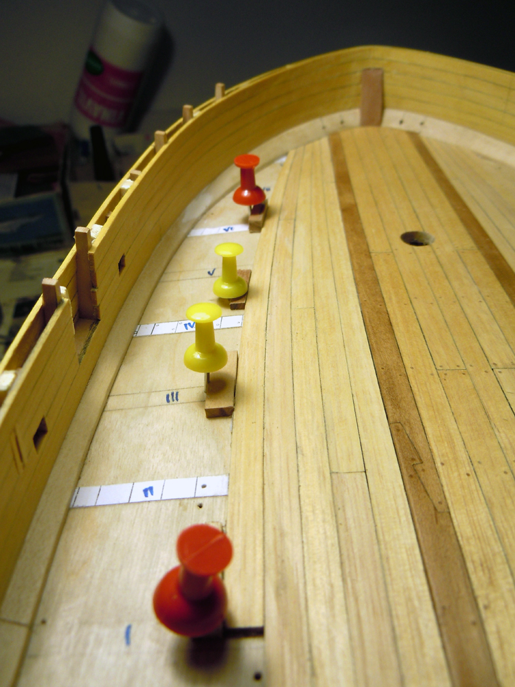
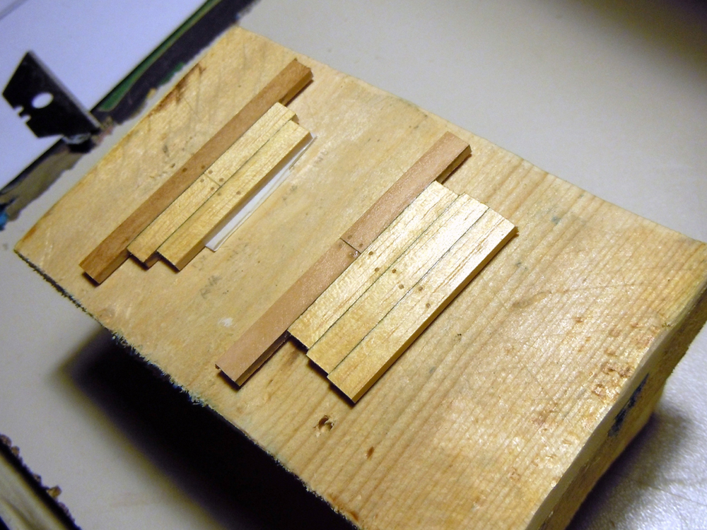
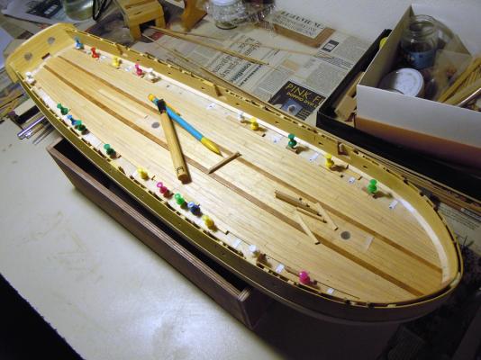
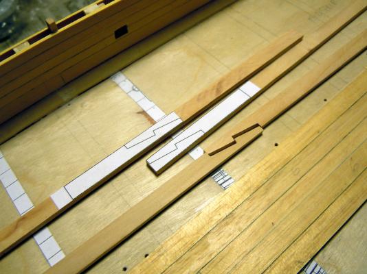
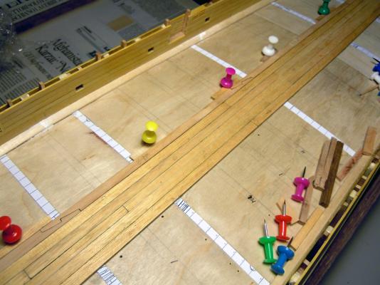
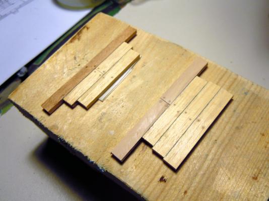
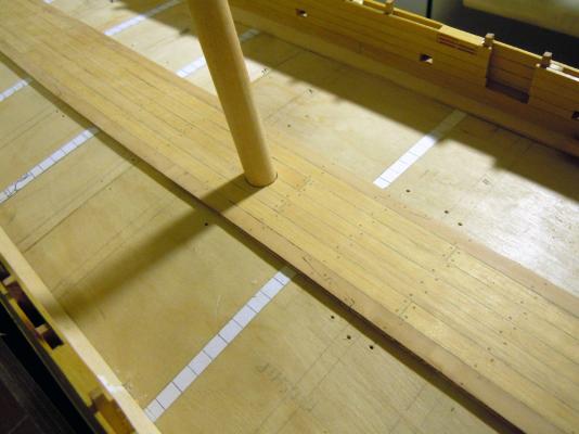
April 13th, 2015 Hi all I’ve some new pictures to show with a small update from my shipyard of “Le Brick de 24”. Not a busy period this, with several days of relaxing holiday and marvelous food in the beautiful Tuscany (before) and in the even more gorgeous Emilia (after), from the cuisine point of view I mean!! I’ve left the shipyard with the start of the deck planking, and some discussion about hook scarph joints for the master planks. So here it is the central band of thicker planks (2.2mm ramin wood, 5 planks of various widths, 2 bulkheads of plank shift). The caulking is simulated with 2B lead pencil, which I think it’s still a usable method even in 1-48 scale: visible (a bit better after a coat of finishing is applied) but not imposing. The texture of Ramin wood is visible here and even better in the following pictures: it’s a bit large but I like it. This is my first attempt at cutting the hook joints. As I was totally new with this type of joint, I printed several paper templates and pasted them to the pearwood planks. The hooks are 20mm long and their end width is 1/3 of the plank width (which is 5.5mm wide). I also tried 10mm and 15mm lengths, but the 20mm just looked better! Above in the picture are the glued templates, below my first hook joint... ... and this is the completed starboard strake with 3 joints: After having completed the pearwood strakes, I realized that the color contrast was a bit too low: I expected something more conspicuous! So I prepared a couple of templates to test the effect of the final finishing and some stain. On one sample I used a Teak stain to darken the pearwood a little bit, the other sample is left with the natural color. In the first picture are the unfinished samples, in the second picture the samples are shown after a coat of sanding sealer that I’m accustomed to use as final finishing. By comparison, it is evident that the color shade is not significantly changing with the finishing, but only becoming a bit more ‘honey’-ish (well, maybe it is not so evident in the pictures, I see, but it is in the real wood: see last picture below). So in the end I decided to go with the stain for the pearwood, but only after having completed the installation and sanding of the master planks and tree-nailing of the entire central band. Above pictures also show the tree-nailing that is done with Birch toothpicks. The size is 0.6mm, corresponding to about 29mm in the real world... I hope this is not too large. Its pattern is quite standard, but I noticed from the plans that the layout of the tree-nails should be reversed from port to starboard... too late now! This is the aft deck while adding the tree-nails... ... and this is the central band completed... ... with a couple of zooms on the tree-nails work with different lighting: Again the complete deck after re-drilling the holes for the dummy masts: And finally this is the central band after application of the Teak stain to the two side strakes of pearwood and also after the application of the finishing sealer, that enriches the depth of wood colors: Maybe it is not evident in the pictures above, but the planks are tapered toward the bow and the poop, and consequently they are curved inward toward the center-line. Not too much so far, but it’s going to increase greatly with the next planks. This weekend I spent most of the time in doing what we in Italy call “Spring house-cleaning”... not meaning that we clean our homes only once a year... just a deeper cleaning that wives require sometime But while cleaning, we also had to face an invasion of ants, which decided our home was worth visiting just in this period of the year ... maybe they wanted to participate to the extraordinary event!! In the few spare time I had I tried to cut the remaining deck planks, but suffered a major fault to the table saw: so I’ve spent another hour completely disassembling the machine in every possible part, checking (and cleaning of course) and reassembling... why I do have this screw remaining out??! Re-open the case, check where a screw is missing, re-close, test... ok, now it’s working smoothly as required! So I’ve got my 80+ planks ready only yesterday night and only managed to glue the first two at the bow. I did some calculation: 10 strakes are needed for every side, each is made by 4 planks, so in total 80 pieces are needed (plus some spare just in case!). Deck planking in progress... stay tuned Fam


-
Hi all for the records, I've finally found (credits to 'daves') what is the type of wood I'm using for the bulwarks: Brazilian Satinwood, also known as Yellowheart, or Yellow Heart, Amarello or Pau Amarello... http://www.woodworkerssource.com/Satinwood_Brazil.html Botanical: Euxlophora paraensis Best regards Fam
-
Thank you Bill actually I've already prepared a couple of samples of tree nails, to check how it comes out. I'm intentioned to tree-nail the entire deck and the visible (not painted) part of bulwarks. I'm going to use birch toothpicks. Bye Fam
-
I did it! Managed to complete the port strake with 4 hook joints... very proud of myself!! Now hope to manage doing the same on the left, then will glue the two strakes and sand the entire central band before proceeding with the side bands. But this will be after Easter holidays, so Happy Easter to all MSW members! Fam
-
This is an example of what I mean... Thank you for your attention Fam
-
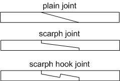
Hi all many thanks for the likes! Yesterday evening I've completed the planking of the deck central band, 5 strakes of Ramin. Today I'd like to install the last two strakes of pear wood, the "king" strakes. I'm using a different wood to highligth the difference w.r.t. the standard planking, but not too much: so I'm using a light shade of pearwood which is quite similar to Ramin but I know it will come out a bit darker when applying any type of oil or finishing product. But I would like to remark better the difference of this strake, so I'd like also to use a different butt joint as opposed to the standard straight athwarthship type. As Ancre plans are not helping in any way on this topic, I'm asking opinions here... I think I have two possibilities: - scarf joints - hook joints These were used with different scopes, hook joint is (to me) a structural joint permitting to transmit stresses along the strake. So probably it better suits the scopes of the "king" strakes, that maybe is not merely decorative... Any opinion or idea? What was the standard contemporary practice? Thank you in advance for any suggestion Ciao Fam
-
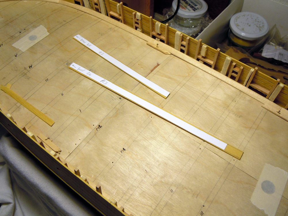
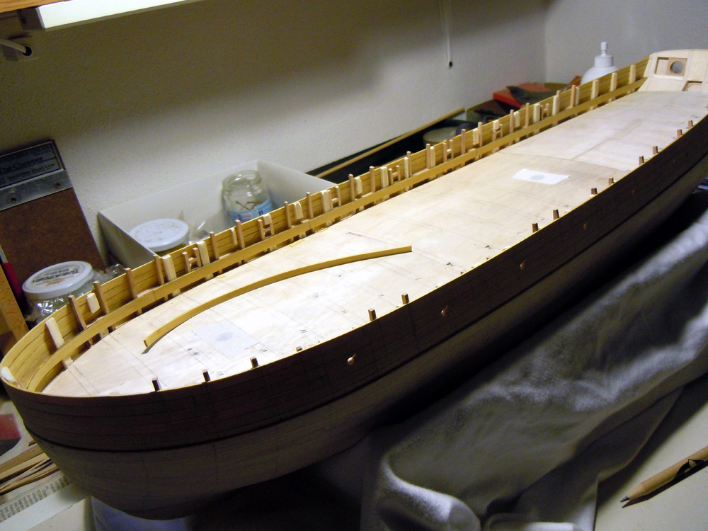
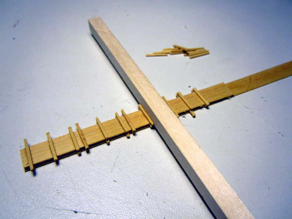
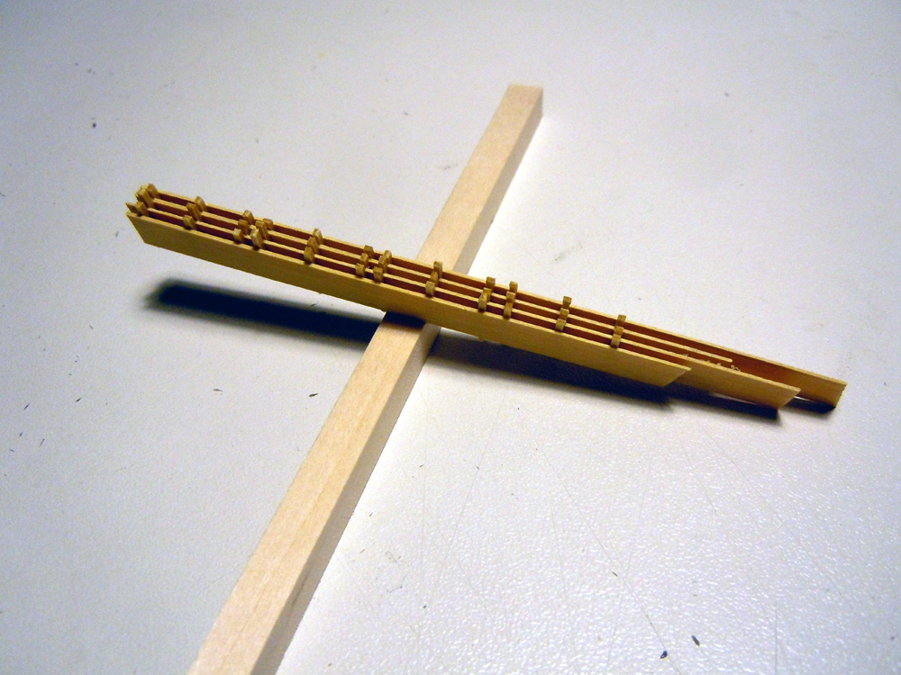
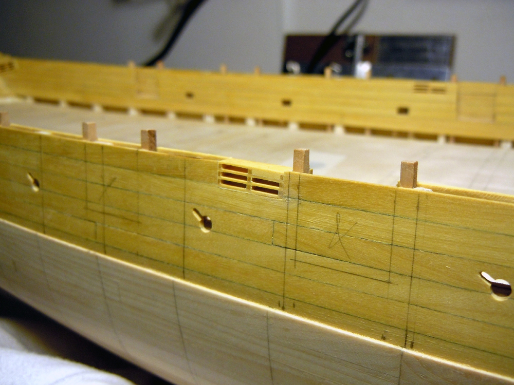
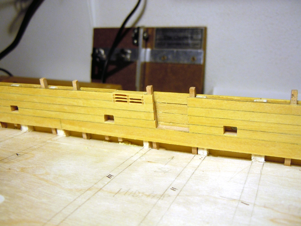
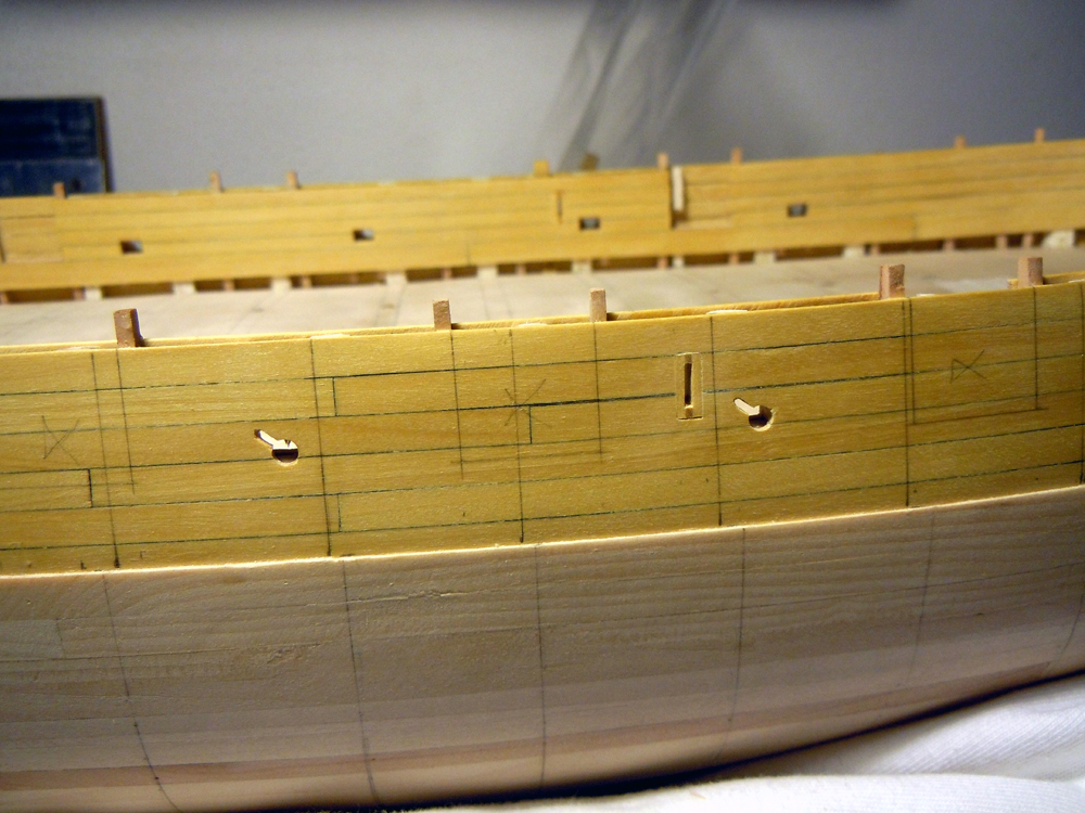
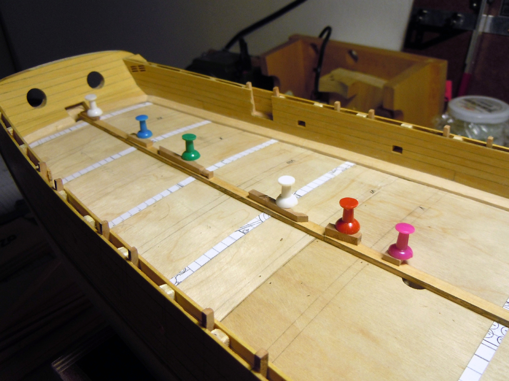
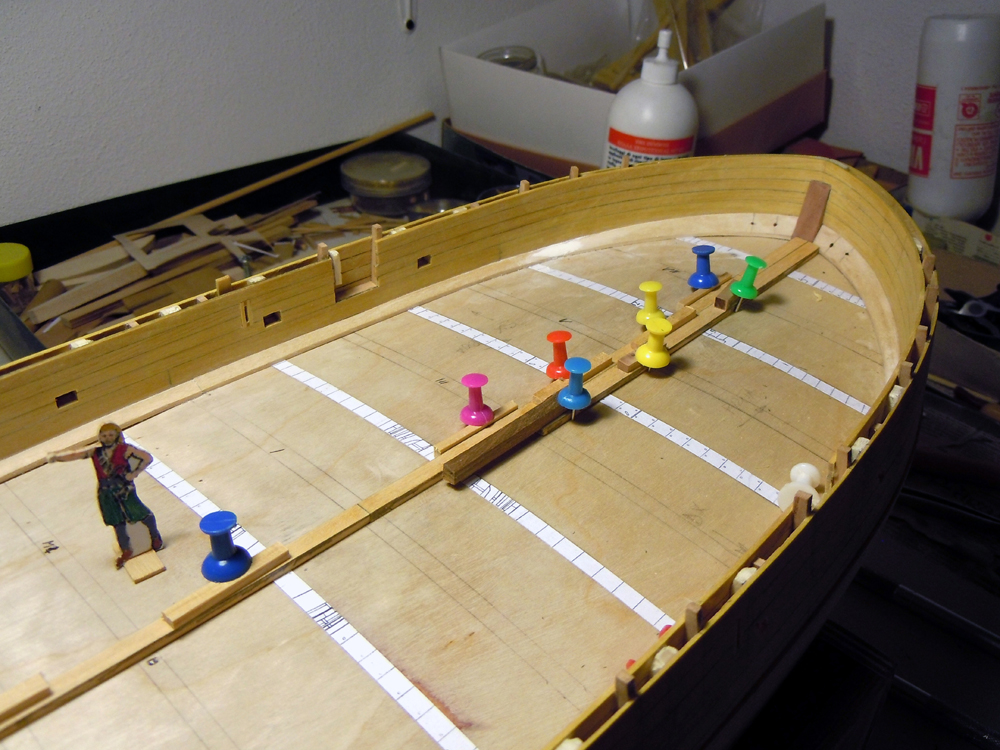
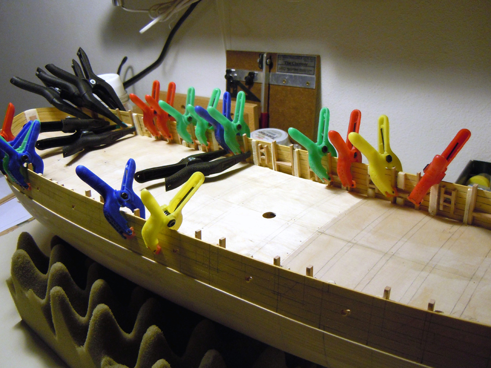
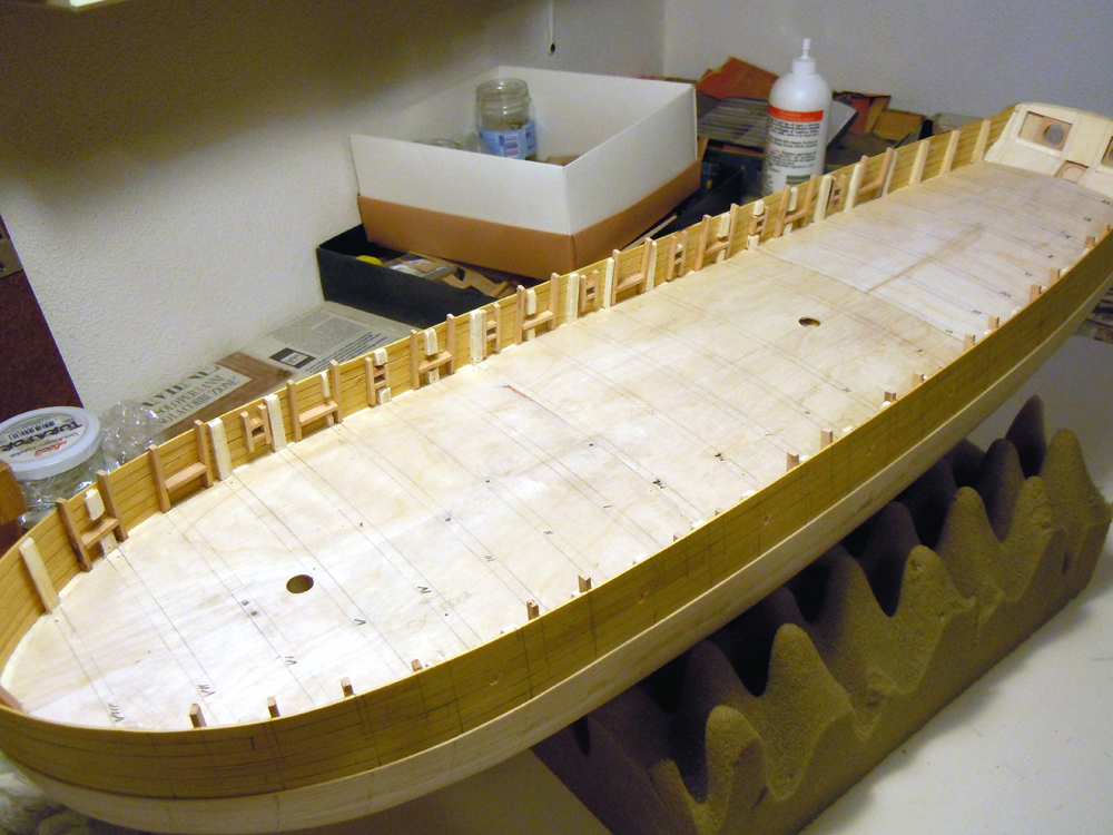
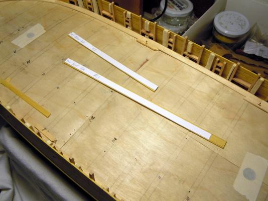
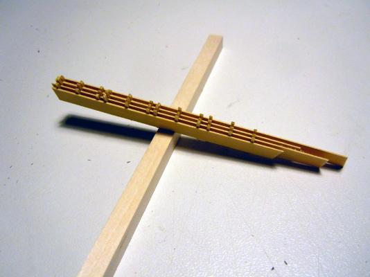
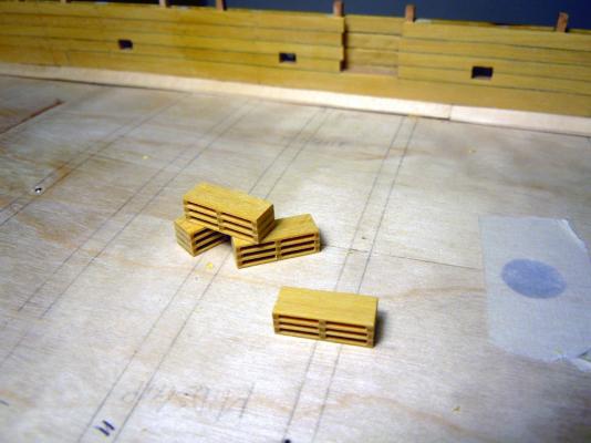
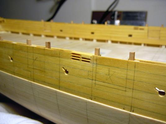
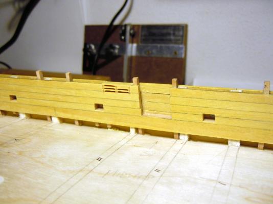
March 30th, 2015 Hi all, here I am with another update from my shipyard! During these 2 weeks I managed to complete 4 tasks on the deck structures: - completion of the bulwarks internal planking - completion of the waterways, with the addition of those at the transom - planking of the transom - preparation and fitting of the 6 sheave blocks in the bulwarks The first internal plank at the bottom of the bulwark is a wider one and needs some adaptation to match the curvature of the waterways. The technique I used is described in the previous post, so no need to repeat. The next picture shows two planks with their paper templates... ... this shows the first strake completed, with a bent plank for the second strake ... ... and this shows the last strake of the starboard bulwark fixed and glued... The transom required a special attention due to its double-curvature: I had firstly to prepare the waterways for this area... the plans are not very clear about this, they show what appears to be a smooth transition from the deck planking to the counter planking more than a sloping waterway as for the bulwarks. So I prepared a sort of margin plank, only creating a small step to house the deck planks on one side and the counter planks on the other side. The counter planks are curved and tapered and are interrupted in the middle for the rudder hole. The starboard transom margin-plank is done (just left to cut to final length) and the port one is being shaped... Note that the transom gunports are shut: I had to add a thin layer of pear to get the correct thickness of the gunport lining. I re-opened the gunport just after planking the transom. So, here are the bulwarks, counter and transom completed with their internal planking. The waterways are still temporarily positioned, not glued yet. The bulwark planking is 1mm thick boxwood, while transom-counter planking is just 0.7mm thick. The bulwarks are not completed without their multiple-sheaves blocks. There are 6 of them: two with 6 horizontal sheaves each at poop, two with 5 horizontal sheaves each at the waist and two with 1 vertical sheave in the forecastle area. The multiple blocks are as wide as the bulwarks, so tapering upward from 5 to about 4.5mm. They are 5.5mm high and about 15.5mm large to house two series of 3 sheaves. The slots for the sheaves are about 1mm high, as can be measured on the plan, so I had to build a block 5.5mm high with 3x1mm slots, and the remaining thickness is left for the 4 spacers... just 0.6mm each! I think I reached the limit of my KS230 table saw, or very close, as I managed to slice 0.6mm layers from my 8mm thick boxwood with almost no imperfections... I’m a big fan of the Proxxon machines, even if this table-saw is a bit underpowered it always gives me great satisfaction! Next I prepared the spacers, 1x1mm, and also a 6.5mm square batten for aligning the spacers while gluing. Here are the steps: One slot in two of the above blocks is than blanked with a scrap piece of boxwood, so to create the 5 sheaves waist blocks. Preparation of the vertical single blocks was similarly accomplished, just with different measures. All the blocks were left wider than the thickness of the bulwarks, to permit a following better and easier finishing. The following task was to locate the blocks’ positions and to create their housings: easy-peasy for the forward-most 4 blocks, but it was a nightmare for the 2 rearmost blocks which are upward sloping and almost in contact with the transom. I had to partially dismantle the bulwarks where they join the transom in order to create the housings, then rebuilt them after having positioned, fitted and glued the blocks. Here is the result: After all the blocks were glued, I only had to sand them flush with the internal and external surfaces of the bulwark, and the job was completed with a good pass of abrasive paper for a smooth finish. The sheaves will be added later: they are 1mm thick (or slightly less) and 5mm in diameter... I'm thinking of using styrene plasticard ... will see how it works! The fourth and fifth pictures above also show the completed oarports, from inside and outside: their pearwood lining is also partially visible. The gunports are similarly prepared, but will be cut only after applying the second planking or, depending on how I will schedule the works, before fitting the gunwale. Finally, yesterday I’ve spent 3 hours cutting the deck planks with the table saw. The deck has a central area of thicker planks, 3mm, where all the deck fittings are installed (companionway, pumps, capstan, bitts, binnacle, boat supports and so on) and two side areas where the planks are thinner at 2mm. These thicknesses are referred to the top of the deck beams, so must be diminished by the thickness of the plywood false deck (i.e. 0.8mm). The central area has planks of different width, not too much but very evident. The central plank, along the ship center-line, is 5mm wide; then there are two planks each side of it, of 6mm width; finally another plank per side of 5.5mm width (total 7 strakes). These measures are taken at bulkhead 0, or M1/M2 in the model, where the planks have their maximum width. Then they are tapered toward bow and poop (with the exclusion of the central one) and slightly curved inboard. JA has found a brilliant way to set a guide for planking the deck with all the above variations, that is gluing to the false-deck several paper strips directly taken from (a copy of) the deck plan: this gives a continuous reference for the planks width to be used, as well as for tapering, greatly helping in preventing any error or inattention... thank you very much JA!! So, here below is the deck prepared with the paper guides: After this, I glued all the waterways pieces and smoothed their joints with some wood filler: these will be painted black later. Finally I started laying the center-plank from stem to stern: lot of care is required to lay correctly this first strake, as it will be the guide for the remaining deck planks. About the wood: it is Ramin for all the deck planks with the exclusion of the two “king” strakes, those by 5.5mm width at the boundaries of the central thicker band, which will be light pearwood. In the last picture the first plank of the second strake is being glued. To build this plank I measured its width at the stations were the paper guidelines are set (bulkheads nn.VIII, VI, IV and II), and pasted these measurements to the plank; next I tapered the plank with the disk sander. This plank will not be bent, because the center strake is not tapered nor curved, but with the following strakes I will have to add a slight bend after the tapering... hope it works, or I will need to take advantage of the full original plank width (10mm) to cut-out the correct shape including bending and tapering (that's to say spiling it!): this is why I only cut the amount of planks sufficient for the central thicker area, just in case they do not fit! Last details: - the planks are cut to 200mm length, equivalent to a bit less than 10 real meters. - I used a plank shift equivalent to two bulkheads - the butt joint of the planks with the waterway is apparently flat in the plans, but only the central portion of deck planking is shown. So I’m planning to use joggled planks starting from when the planks need to be mitered about 45° to match the waterways... same method as explained in the fantastic tutorial by Ed Tosti, a method that I’ve also used in my Pinco: To conclude, I have a consideration about deck planking: the deck fittings were fixed to the structures (beams) under the planking, so in theory they could be installed right now and then the planks cut to fit around them. I tried this approach with the Pinco, but then had lot of difficulties with the deck sanding, right because of the many obstacles in the way. So I’m now trying to add the fittings ‘on top of’ the planking, by cutting the required slots where needed for greater strength (for example for the bitts and pin-rails). That’s all for today... my best regards Fam


-
Cristine stain will not be taken if the wood fibers have absorbed some glue... well it also depends by the type of glue, but this is a general rule: so it's very important that you wipe off any trace of glue before it sets, while assembling. Sanding takes care of this, but not completely: again, much depends by the type of wood (how much 'open' are its fibers) and type of glue. Sanding also removes some, if not most, of the stain so you will have to re-touch and refine it if you are going to pre-stain the parts. These are more or less the pros and cons about what you asked. From your pictures it seems to me that the planking is not klinker, so it will be easier for you to sand the hull properly smooth and fair: my suggestion (what I would do in this case) is to assemble, taking lot of care of any excess glue, then sand smooth, then stain. I also suggest white glue (or PVA or carpenter glue or Vinavil, as it is sometimes called, depends by Country), it is easier to manage even if takes a bit more to set Hope this helps ciao Fam
-
Welcome onboard, this is the perfect place to start... just ask if you need something or feel uncomfortable with any instruction or procedure, there are lot of master shipwrightes here! Fam
-
Welcome back!! Fam
-
Papegojan 1627 by mati - FINISHED - 1/48
Fam replied to mati's topic in - Build logs for subjects built 1501 - 1750
Absolutely beautiful! Great job and great metal work, Matt Fam -
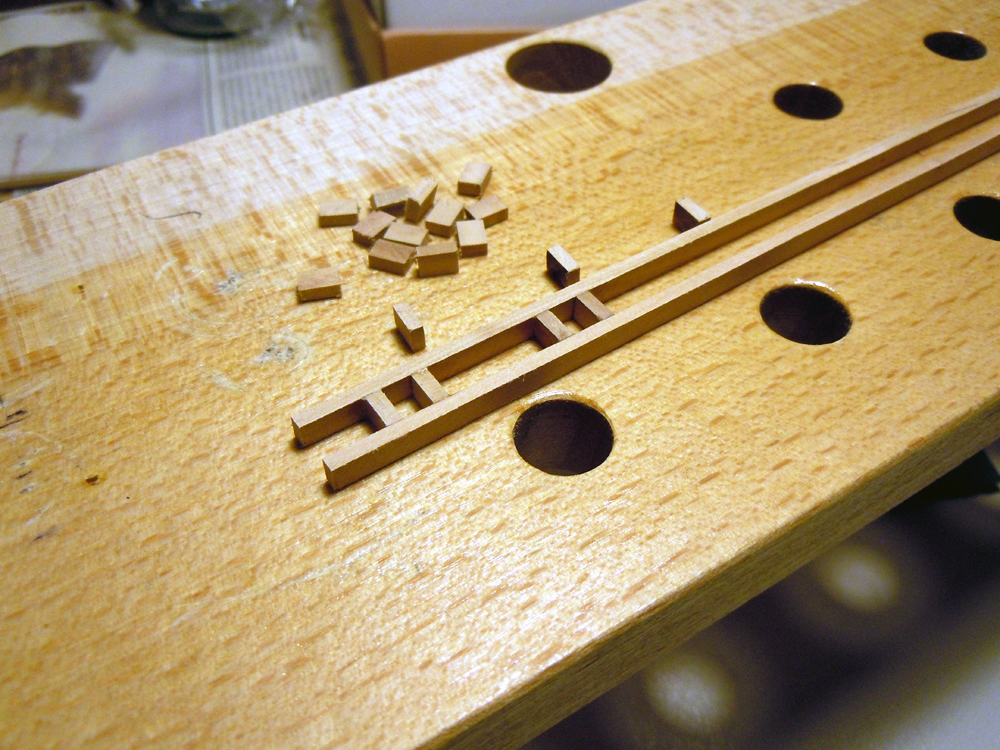
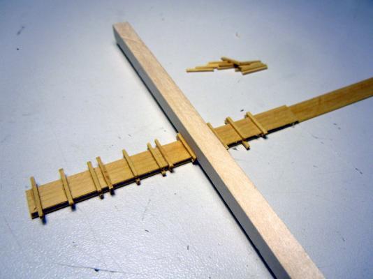
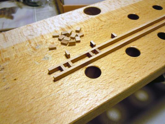
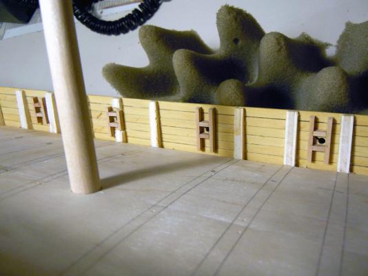
March 13th, 2015 Hi all another small update from my “Brick de 24” shipyard... I’ve been working all these days (slow paced, I admit) on the inside of the bulwarks to prepare the gunports and oarports framing. First step, after locating the position of the oarports, was to drill and cut them. My conclusion from the above discussion was that the slot for slipping through the oar blade must be positioned backward and upward, so this was the result from outside: Note how the oarports are aligned to the plank strakes... this was the leit-motiv for all the alignment checks, greatly helping this difficult task also for the framing. Next was the preparation of the oarports framing: I decided to work on the bench, because it’s easier, quicker and less time consuming. So cut several strips of pearwood, the same lighter quality I’ve already used for the transom gunports lining. They are 2mm thick and wide enough to match the maximum thickness of the top-timbers at the bulwark base. I cut much more strips then I needed for the oarports, as they are the same also for the gunports framing. Then cut a couple of these strips into 5.5mm pieces, which is the width size of the rectangular ports (see above drawing). Material preparation took no more than 5 minutes, the table saw is great for this job! I then sacrificed 3 of these pieces for preparing a very simple jig: they just serve as spacers for the two long battens, fixing their correct distance. Then marked on both battens a series of 4.5mm long segments parallell to each other, and simply glued the remaining pieces between the battens using the markings for their alignment. The result is visible below for two ports, but I managed to prepare 7 framings at a time in this way! Each framing is well spaced from the next, because my intention was to use the long legs as a replacement of the top-timbers that I was going to remove. Here it is how: Almost the same procedure was used for the gunport framing, but this time I worked directly on the model because the framing structure is not boxy-like, so needs a more attentive positioning to respect the required alignments. Firstly I had to transfer to the planking inside the gunports markings, then (with the positions of the battens defined) I cleaned the internal surface of the planking from any residual of glue and prepared for a good matching with the battens. I cut them slightly longer than needed, to let for some fine adjustment, and then glued them in position... JA had warned me that I was going to encounter some difficulty, because of the many top-timbers interfering with the framing positioning... well it was partly true but only slowed down my job because I had to proceed per steps: - firstly I glued the battens in the free positions, and let them dry - then, with the installed battens strengthening and supporting the bulwark, I cut the interfering top-timbers - most of them were only narrowed, leaving as much material as possible to avoid weakening excessively the bulwark: it was a time consuming and delicate job, with small shavings at a time, then cleaning, then shaving, then cleaning... - a couple of top-timbers had to be completely removed - when all the vertical battens had been glued, I started with the horizontal gunport sills: measurement was important in this case, because they must be parallel to the deck and to the gunwale (top edge of bulwark) and exactly at 16.5mm from the gunwale. - again, in most cases I had to remove portions of top-timbers where they are located exactly in the middle of a gunport. The following are shots of the works in progress and of the final result (starboard side). As you can see I had to proceed in parallel port and starboard, in order to wait for the glue to set. After this job was completed, I had to reduce the thickness of all the framing pieces to match the correct thickness of the bulwark structure: 3.5mm at the base, 2.5mm at the top, another very long job to be done, because the correct alignment of all these battens is affecting the flow of internal planks! Once again, JA method was much easier and quicker but I’m not sure if my good friend managed to get the variable bulwark thickness with his method... I will ask him Finally, this is a shot of yesterday evening work: the first internal plank is glued! This plank is the most difficult of the first (lower) strake, because its lower edge has to match the rising waterway while the upper edge has to remain parallel and 16.5mm down from the top of the bulwark... this also means that this strake is wider than the other, because the combined height of the waterway and 1st strake needs to match the total height of two strakes on the outside. I had to use one 8mm thick boxwood piece (the maximun I own), and sliced it into 1.25mm thick planks... luckily I had just bought a new “Super-cut” blade for the table saw, because the older one was too worn to go through this hard wood! Having the table-saw set, I also cut all the planks for the bulwark inside: 5mm wide (to be reduced), 1.25mm thick. The shape of the above plank was defined by slipping a piece of thick paper between the waterway and the bulwark framing (another reason for not fixing the waterway! ), then the pencil was run along the waterway upper border (thus marking the lower plank edge shape) and along the top of bulwark external planks. The latter marking gave me the reference, when lowered by 16.5mm, for the upper edge of the plank. This template was then transferred to one 8mm wide plank and cut. Then curved (as usually, by water and heat), measured, fine trimmed below and above, until I was totally satisfied. Note how the upper edged of the plank matches the sills of the first two gunports! And finally... it was glued in position! 2 hours to get this result... The forward waterway piece was left in position for a while, just to be sure that the plank was correctly positioned, and then removed to avoid it to remain glued by any excess of glue from the above plank, which I want absolutely to avoid! The next job should be slightly easier, as the remaining planks of the 1st strake are constant width... just a matter of matching the distance between the top of waterway pieces and the gunport sills. Stay tuned Best regards Fam


-
This is really an excellent result, I'm going to print out your sequence and use it as a tutorial for my Brick!! Ottimo lavoro! Fam
-
Hi all just a check on the correct wording I should use in English, if anybody can confirm... - camber = curvature of the deck athwarthship, i.e. in the port-starboard direction - sheer = curvature of the deck longitudinally, i.e. in the stem-stern direction thank you in advance Fam
-
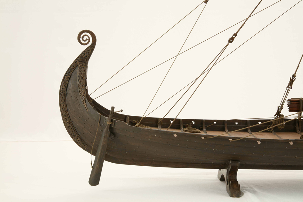
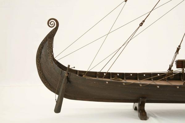
Thank you, I'll consider your point and think a bit more about it I add another picture for helping the discussion: the Oseberg Drakkar (slots oriented backward) Regards Fam
-
Yes druxey if I assume a 5mm drill bit diameter in 1:48 scale, it makes 240mm in the real world. Your 30cm correspond to 6.25mm diameter of the hole in 1:48 scale, so if I drill the hole with a 5mm bit and then finish it with files, it will end up to something between 5 and 6 mm... Fam
-
Well, to me regardless if the man is pushing or pulling the handle of the oar, seating or standing, the fulcrum of the lever (oar) is pushing agaist the hull in the direction of ship/boat motion.... that makes the ship/boat move... Then agree with Carl that on a ship of the size of a Brig it's probably easier to stand facing forward and pushing forward on the oar handle (similar to the way rowing is done on a Venice Gondola), while on a small boat its easier rowing while seated, facing the stern, pulling the handle. So I think that if the shape of the hole in the bulwark is regular in the forward side (i.e. no slot), as forward is supposed to be the most used direction of hull motion under rowing, the strenght of the wooden parts subject to friction should be greater... or not? I've searched in the monography for other information but have not found anything more than that little sketch Thank you again, I really appreciate your help and, if no other idea or illuminating picture pops up, I'd proceed by cutting the slots backward and upward Fam
-
Thank you druxey these are the data about the brig size I've found in the monography, related to the Cygne: lenght (transom to stem): 33.50m widht (hull, I suppose including the channels as the hull alone is 7.50m): 9m hollow (? "creux" in french): 4.59m displacement: 537 tonns main anchor: 1100kg 2nd anchor: 950kg 3rd anchor: 750kg 4th anchor: 330kg 5th anchor: 279kg I know probably it's not enough, but I've found only these numbers with a quick search. Thank you Fam
-
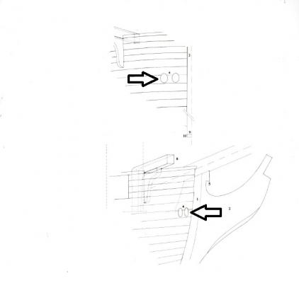
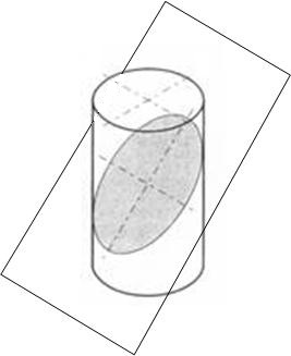
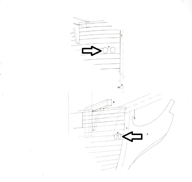
Yesterday evening I did my homeworks, and arrived at the conclusion that the plans are somewhat imprecise on this detail, at least in the side view. Here is the extract of the plans I'm working on: The details pointed by the arrows should, in theory, permit to verify the size of the hawse holes. In theory only, because: the bow in this position is sloped about 10deg from the port-starboard direction (square to the keel) using cosine function on the dimensions taken from the upper figure (front view), the width of the hole is 5.07mm vs a 6.5mm height using the sine function on the dimensions taken from the lower figure (side view), the width of the hole is 15.5mm (! absurd!) vs a 6.4mm height So my conclusion was that the drawing only shows a guideline for localizing the hawse holes but they are not perfectly drawn to size, at least in the width direction. Another consideration from the above comments, which took some time to enter my mind : when a cilinder (the hawse hole) is intersecting a flat surface (the hull exterior) at an angle different from 90deg, the resulting intersection shape is an ellipse!!! So, it is not completely incorrect that the shape of the hawse holes is elliptic on the external hull surface, provided the hole itself is circular in its cross section! But what is the diameter of the hole, i.e. the size of drill bit I have to use? Probably (to be verified), as the axis of the hole is almost square to the hull surface when seen from above, I could consider the width of the oval in the upper drawing (5mm) as a first attempt... if I consider an approximate slope downward of 45deg for the hole, and the hull surface vertical (which is not, but just an attempt!), then 5mm divided by cosine(45deg) makes 7.07mm, that is pretty close to the 6.5mm height measured on the plans Any other consideration or suggestion? Thank you all for helping me thinking!! Fam