HOLIDAY DONATION DRIVE - SUPPORT MSW - DO YOUR PART TO KEEP THIS GREAT FORUM GOING! (Only 36 donations so far out of 49,000 members - C'mon guys!)
×


Fam
-
Posts
185 -
Joined
-
Last visited
Content Type
Profiles
Forums
Gallery
Events
Everything posted by Fam
-
 JA I'm really impressed! All that thinking produced an outstanding result, like very much the choice of colors. And confirm you, with an "exterior and independent eye" that the caulking is SUPER!! Even the trick of the paper strips is very smart, I suspect that I will copy it... Thank you for sharing and a big CIAO from your fellow-builder in the "Company of the Brick" Fam
 -
Ciao JA, you did an excelent job with the waterway, indeed! Are the bow pieces built by two battens that you have bent and fine-shaped with the band saw or are they cut from a tablet? And what about the gunwale? Is it definitive? Ciao Fam
-
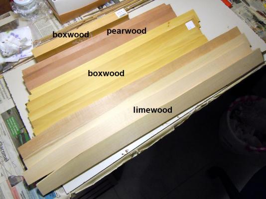
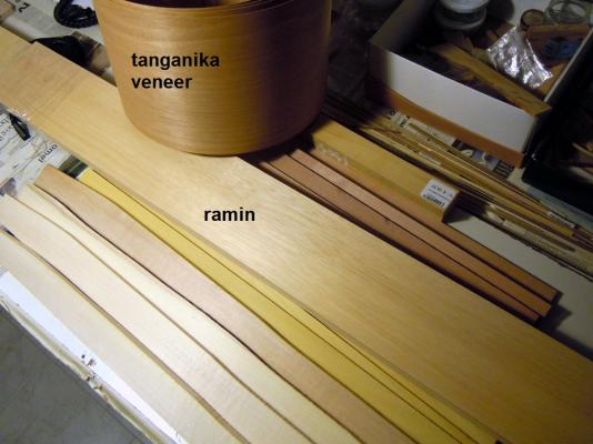
Hi all may I ask if anyone ever saw a boxwood colored like the one in the picture (the one below, above is another type)? The yellowish colour is so intense that it's not convincing me... Thank you Fam

-
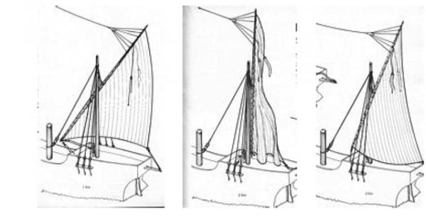
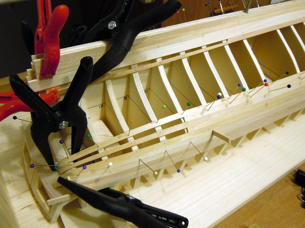
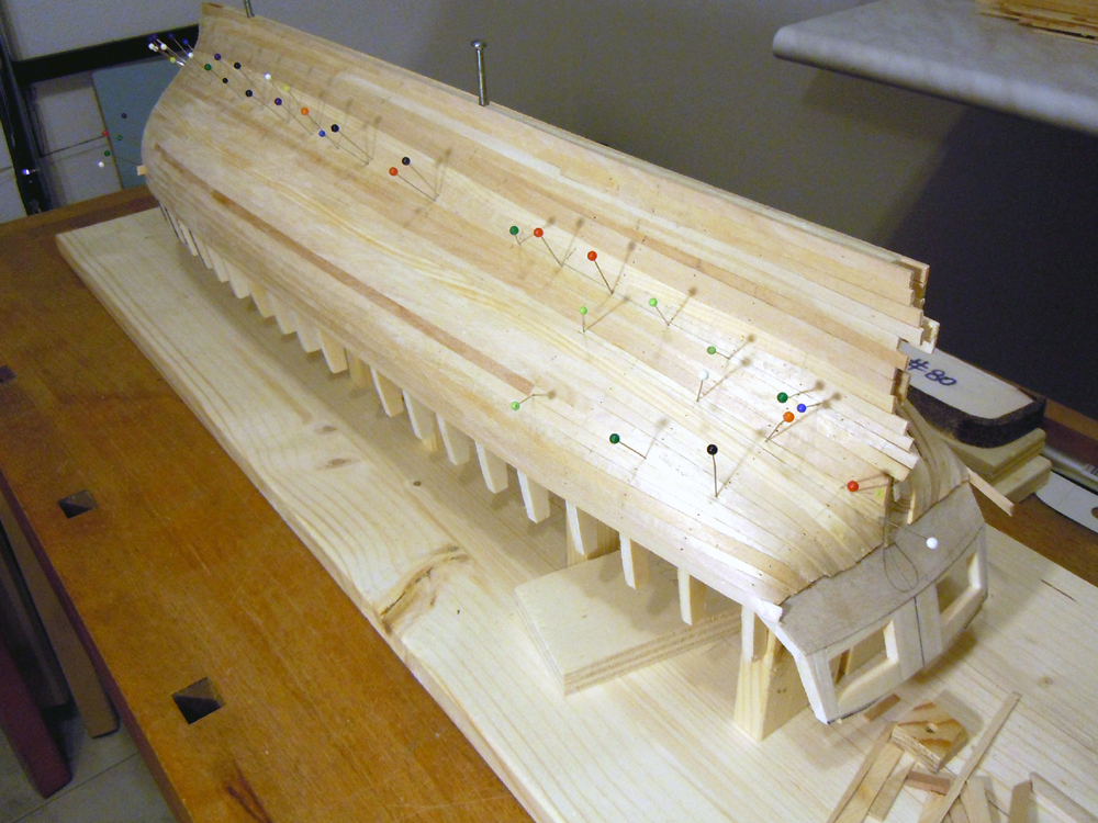
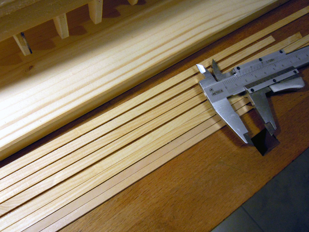
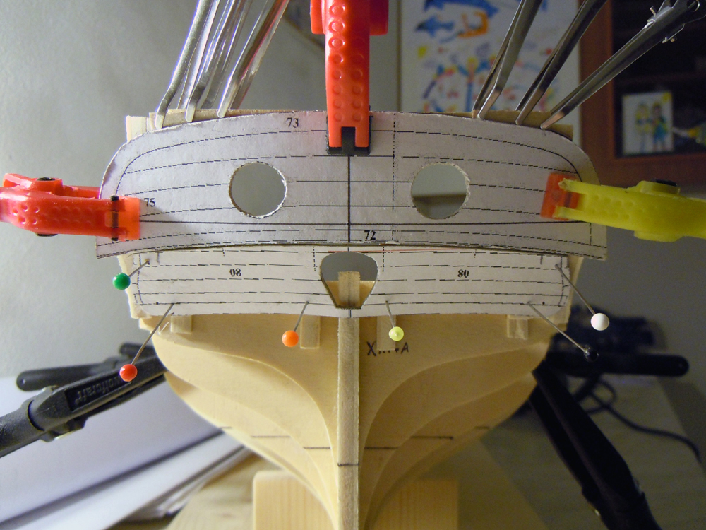
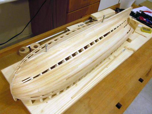
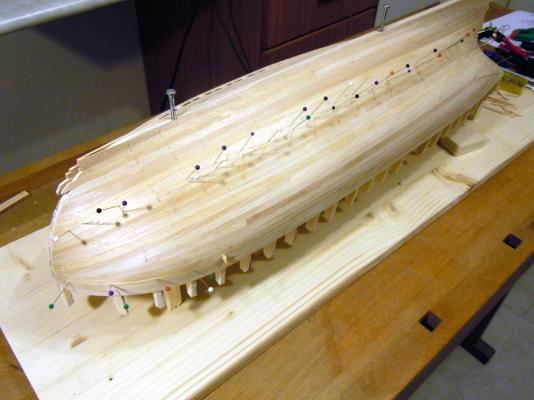
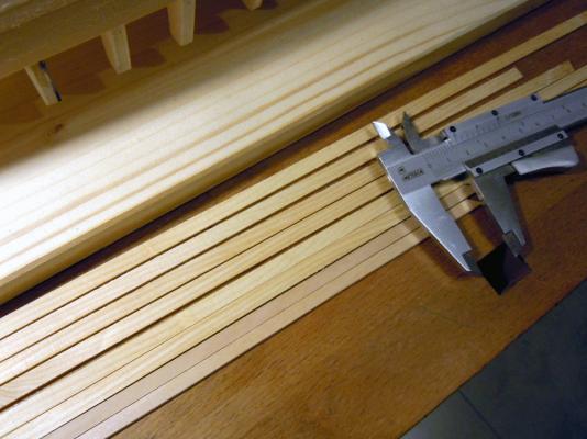
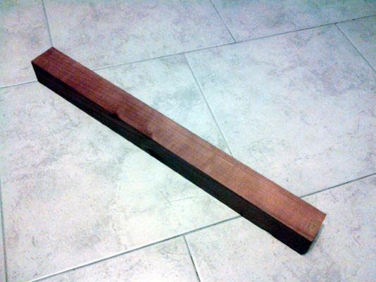
And now I’ll continue with the Brick de 24 December 05th, 2014 Planking, planking, planking... After I gave up with the spiling technique for the first planking, I started at a slow pace proceeding at the same time on both sides. Standard technique, learnt with the Santisima Trinidad kit, standard problems! At the bow the planks, that cannot be curved edgeward, tend to climb up (down in the photo where the hull is capsized) so I had to force them a little bit, as much as possible without letting them to raise from the bulkheads, and to introduce several drop-planks. The same happens at the sterns where the convexity leads to converging planks. On the keel side, conversely, the Garboard plank was easily added and then I started planking downward, with the addition of some stealer where the hull is concave. Can you see all that pins with a tiny plastic ball tip? They are the reason for my fingertips aching... because modeling is a pleasure but sometimes also a pain...;-) Yes, I’m a Queen and Freddie fan!! Consider that I also sliced one fingertip while shaping the stealers... So no more than 3-4 strakes per evening! December 12th, 2014 One week later (while at the same time working on the Knarr), this was the status of the planking... December 13th, 2014 The following evening... December 14th, 2014 ... and finally yesterday night ... Minor milestone achieved: the starboard side is fully planked from the keel to the wale! Next task: complete the port side, obviously... before Christmas I hope ;-) In the meanwhile... the second major milestone: getting the required wood types and having them properly cut and sanded to the thickness I need. DONE!! Firstly, I tried to cut 1.75mm planks from the Cirmolo I already have. Remember? I need them for the wales, to be overlaid above the 1st limewood planking. This is the result: very easy to slice with a "Super-Cut" blade in my Proxxon KS230, coarse pink-ish to beige texture, quite easy to bend, also accepts a good amount of torsion (90deg in a 300mm long strake) and some edgeward bending. But the most amusing thing is... the smell of it! When freshly cut it’s like being in a Swiss mountain hut, all built in wood... I love it! Here is it: And this is the wood I managed to find: Boxwood in two different shades, one is so yellow that seems to be stained, the second (which I haven’t cut yet) is more amber tone. I plan to use it for the bulwark internal and external planking (the yellowish one) and for the figurehead (the amber one). Limewood, the different shades are only due to the orientation of the pieces w.r.t the light. I plan to use it for the deck planking. Pearwood. This shade is much more reddish than the shade I already have. I will use it for the keel, cutwater, sternpost, gunport linings and deck fittings. Tanganika veneer. To be used for the second planking. Ramin. To be used for various deck fittings and guns carriages Not big quantities, but I hope enough for the scopes I intend to use it... Here they are: Best regards Fam


-
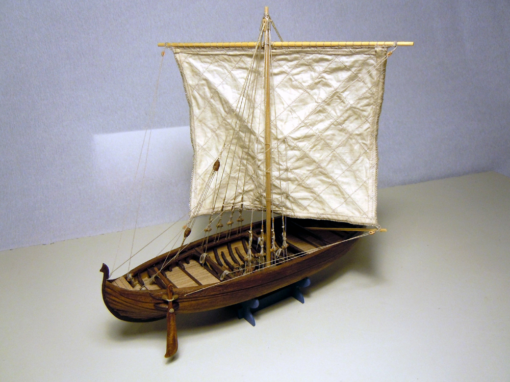
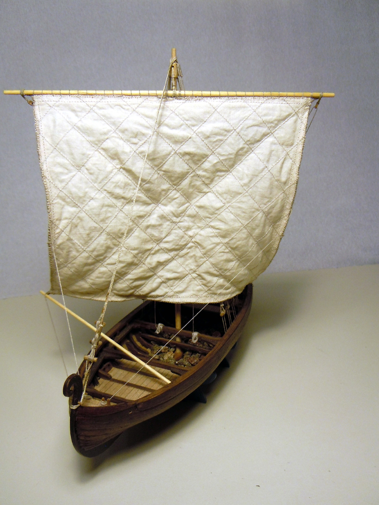
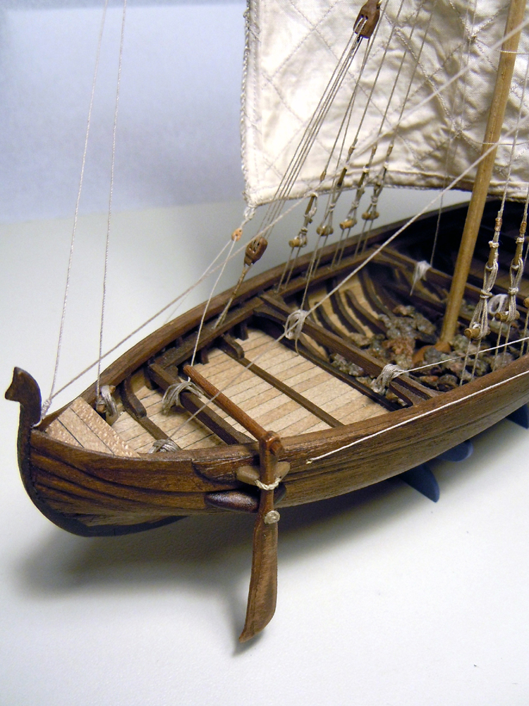
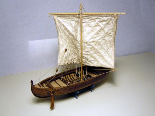
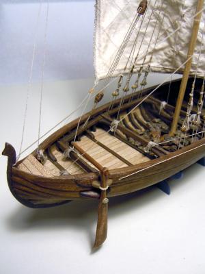
Hi all, I’m back again with the Brick de 24 shipyard! Past two weeks were full of satisfaction for me: I managed to reach 3 milestones, two major and one minor, in my shipyard activities... unfortunately my job kept me far from posting the updates here, so I’ll show you what I did respecting the chronology... hope you’ll enjoy it! December 15th, 2014 First of all, even if a bit Out-of-Topic, I’m proud to introduce you to the first of my major achievements: The Viking 11th century Knarr is completed! It started as a side project, while masting the USS Constitution Cross Section... then the latter was stopped while waiting for the blocks from The Syren Company, and the Knarr become the main project. Then I started the Brick, and it became again a side project, but I continued working on it to give some rest to my aching fingertips (will tell later!)... It is a Dusek small kit, quite interesting and quick to build until the planking phase is started... then headaches started... definitely klinker planking is not easy!! Hystorical sources are... scarce, if not absent. The kit is based on the remaining of Skuldelev 1 wreckage, which can be visited in the Viking Ship Museum in Roskilde, Denmark. I slightly modified the shape of the keel tips, to give it a ... more Viking looking... well, it is intended to be a personal interpretation of a type more than the reproduction of the real ship, but this is the only modification I introduced! Some interesting information on the ship can be found on this fantastic site: http://home.online.no/~joeolavl/viking/vikingknarr.htm and some other information about the building techniques are here: http://home.online.no/~joeolavl/viking/norse-shipbuilding.htm I mainly based my Knarr rigging on the Borgundknarren replica, and on some information I exchanged with Mr Jack Panzeca here on MSW. As this is the build-log of the Brick de 24 I’ll post only 3 pictures of it. General views The helmsman position

-
I absolutely quote Nils, I can't believe how simple and smooth you are making it to appear! Fam
- 1,051 replies
-
- 1
-

-
- cheerful
- Syren Ship Model Company
- (and 1 more)
-
Chuck, I see you are starting the planking wih your usual technique: is the drop plank under the wale a british standard only? Or a common use? I've not given up completely wih this technique, and just bought a roll of tanganika veneer to test the spiling for the 2nd planking, but my hull is French built so I'm not sure which standard I should stick with... Thank you Fam
-
Too easy that way, you don't have the Italian Mail Service!!
-
My copy of the monography just arrived yesterday evening... 30 days from Nice ot Milan... no other comments needed!! FAM
-
Hey JA, you are proceeding at the speed of light !! How do you explain that I'm not able to lay more than 4 planks per day, working in 4 separated areas of the hull, while you are laying 4 planks in a couple of hours? I'm envying you!! Fam
-
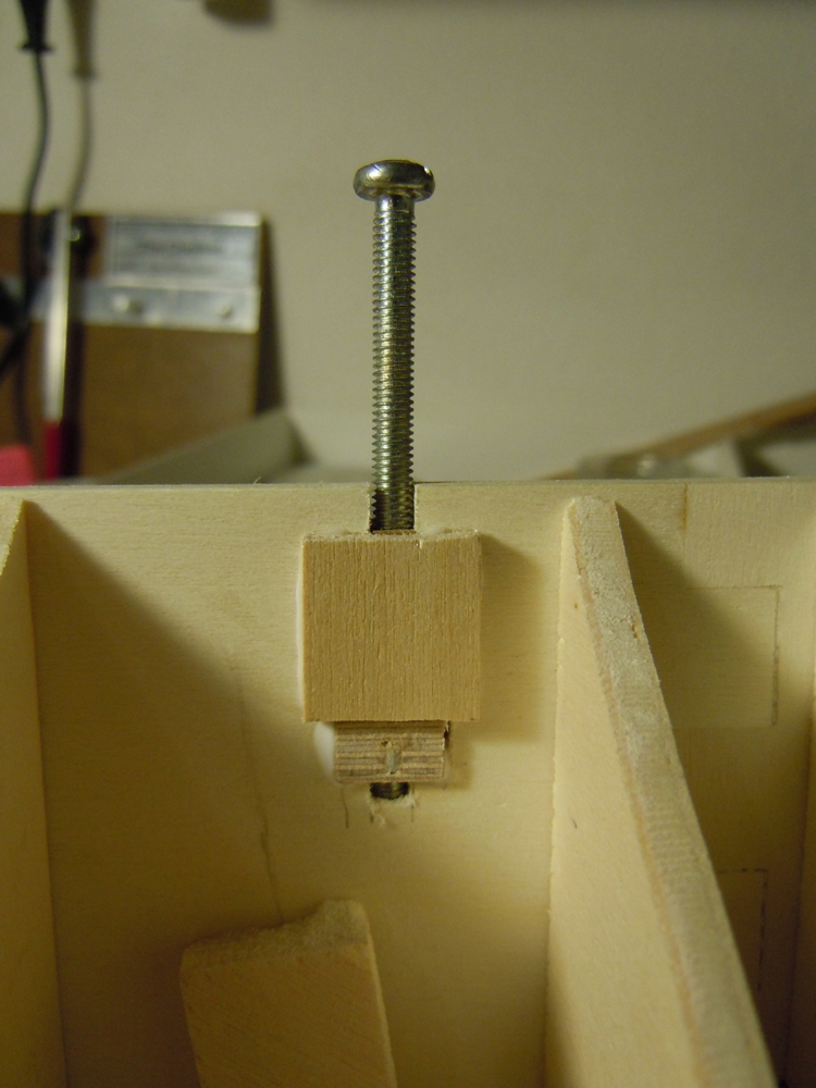
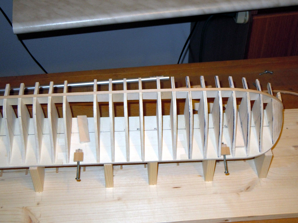
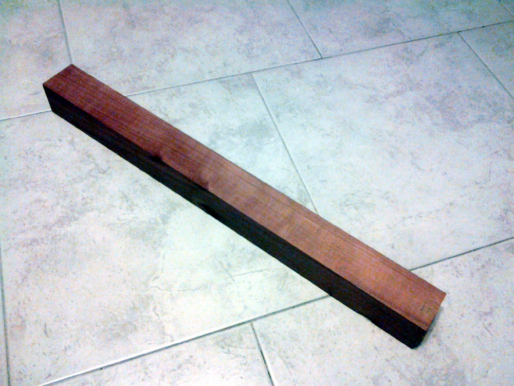
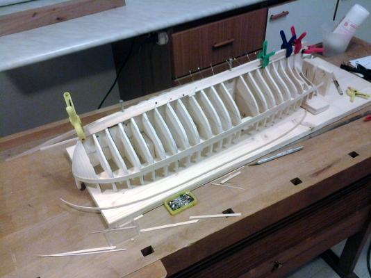
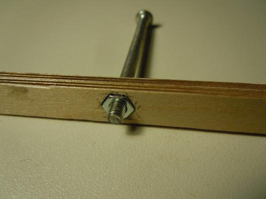
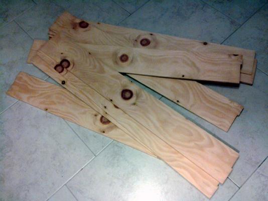
November 28th, 2014 Hi all a small update from the "Brick de 24" shipyard: I’m fully into the planking phase now. I had to give up with my ideas of planking techniques, spiling and all that sort of things: there is no chance for me to get large planks, I only have 5mm wide limewood strips and was not able to find anything else. I took some measurements, following the guidelines of Chuck’s “Lining off your hull for planking” tutorial. But the shape of the hull at the bow is such that spiling is required from the very beginning, even at the wales. So, for the first planking I’m back to my standard techniques, with several drop planks and stealers wherever needed. For the second planking I had some ideas, but first of all a couple of pictures of the model: Sorry for the quality of pictures, my tablet camera is not it’s better feature! But first of all I added to the keel a couple of hexagonal nuts, ready to house the bolts for fixing the model to the display base. This is the first time I try something similar, but (as usual) lot of pictures are available here on MSW, so just copied! Yesterday I had a hard disappointment and my disillusion grow up again, once more after several other episodes! I went to pick up my boards of Cirmolo cut to 6mm thickness, and ... totally useless for my scopes. The texture is too coarse, unsuitable for 1:48 planking to remain in natural wood color. Of course it's totally my fault, due to ignorance on timber characteristics: when I bought the Cirmolo log it appeared as a god choice, the color was appealing, the grain was thin. But after cutting, this is the result: Even if cutting the planks edgewise (which was the plan to get 6mm wide planks), the texture will remain very evident and unsuitable for the bulwarks. So now my hope is back to the original Pearwood, a bit darker but with adequate grain: (the color in the picture is a bit altered). New hope also from the log of boxwood I'm getting prepared right now, we'll see how it looks like! What can I do with that Cirmolo? This is my idea: I'll cut one board into 6mm planks, and will ask the carpenter to reduce another of the boards, the thinner is 4mm thick, to just 2mm (or even 1.5, if possible) thickness. This should be suitable for the wales second planking, finally making good use of the spiling technique. So, stay tuned and a big ciao from FAM


-
Good job, JA we are currently doing the same phase in parallel ! Looking forward of seeing more pictures from your shipward FAM
-
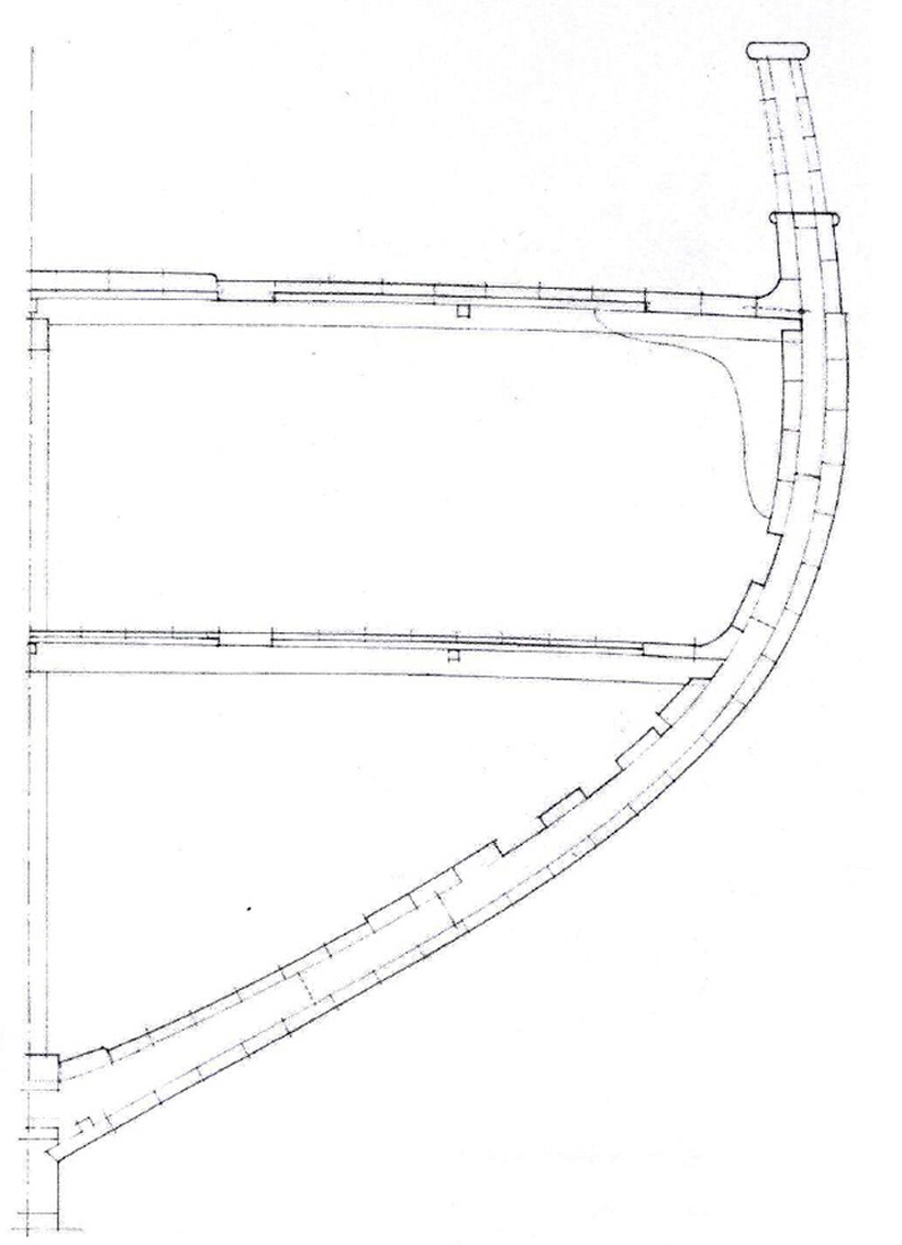
November 24th, 2014 Hi all many thanks for the likes and for the comments, I really appreciate! I've just started applying the first 2 planking strips, from the deck level downward, and another strip for the garboard plank, and confirm the impressions: they go on very easily at the bow, while at the stern it was a little bit more tricky but only due to the shape of the hull just under the transom, at the joint with the counter where a sharp bending and torsion of the planks are required. I've read again attentively (I think it's the third or fourth time, indeed!) the "Simple hull planking techniques for beginners" manual, I'll try to go with this technique as much as possible. Nonetheless I don't have any possibility to get large planks, for using the spiling techniques at its best (as shown by Chuck on the HMS Whinchelsea). I'm not worried very much about this, as the hull will be completely coppered, so the layout of the planking will be hidden by the copper plates. So I'll use as many drop-planks or stealers as required, but will try to comply with the planking "rules" as much as possible. I've not received my monography from Ancre yet, so I'm only relying on a couple of 1:48 scale drawings to have an idea of the number and thickness of planks to be used. The wales will be 2.5mm thick at their thicker position, second and third wale's planks from the top. Then the thickness will gradually decrease to 1.75mm at the bottom of the wale (4 plank rows more below), where it merges into the hull planking without steps. The upper plank of the wale is at deck level and is 2.25mm thick. Above the wale there is a 0.5mm step, and the planks thickness decreases to 1.75mm for the first external plank of the bulwark. From this level upward the thickness further decreases gradually to 1mm at the top of the bulwark. The following picture shows what I'll try to get: How? - For the bulwark planking I'm getting several billets of a type of pine-wood, called 'Cirmolo' in Italian, which is amber-reddish coloured. This part will remain in the natural wood colour down to the gunport sills. Below this level, it will be painted black. - For the planking of the wales I'm using limewood planks 1.5mm thick by 5mm wide. I'll use a double layer at the wales, sanded to the required thickness. - Below the wale I'll still use the same limewood planks and will add a second layer of 0.5mm veneer below the area where 2mm thickness is required. It seems a quite strange approach, but unfortunatly I have always had great difficulty in finding suitable wood pieces to obtain planks and, even more difficult, to have it cut to the suitable thickness. I've got no machines and sophisticated tools, so I always need to rely on external help ;-( That's all for today, still no pictures of the model for a while. Ciao Fam
-
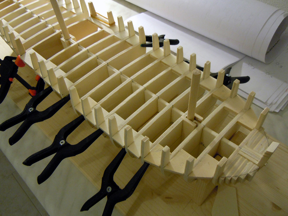
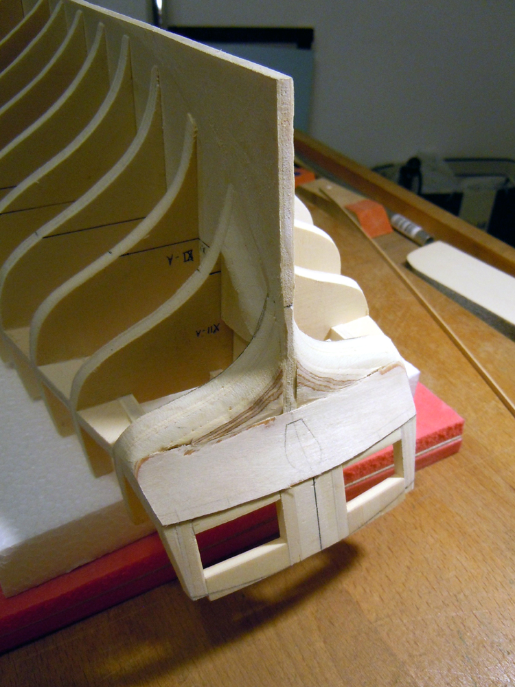
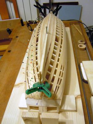
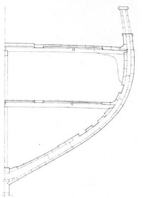
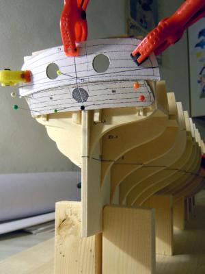
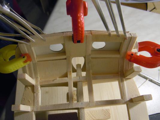
November 18th, 2014 Hi all, some slow progress in my shipyard. Next steps: the counter and hull preparation for planking. As anticipated above, for the lower counter I prepared another cardboard template. I had some problem in getting the correct shape, as the only views I own (my monography is not arrived yet, so I have to rely on scanned copies kindly sent by Jack Aubrey!) are seen directly from the stern, so they are correct in athwartship dimension but compressed in the vertical direction. I had to play a bit with geometry, trigonometry and graphic tools to get the correct shape, but in the end I managed to obtain it. The next pictures show the Counter template dry-tested in position: the hole for the rudder is apparently smaller than required, but the plans provide the correct shape and size for this detail and a section view of the transom-counter-rudder head, for its correct position. So I glued another paper template of the hole to the Counter template and cut the hole to check its position with respect to the false keel and transom timbers. I’m not fully confident about its size, yet: I'll recheck it when the sternpost piece will be available. Nevertheless, this layout permits me to adjust the position of the counter more accurately. I also managed to bevel the template to improve the joint with the transom, so I feel its position is pretty close to be definitive. Another internal view of the rudder hole... ... just showing how the internal transom timbers are exactly separated by the size of the rudder hole. The third picture also shows the last side reinforcements to the transom timbers: this 3rd layer of plywood adds enough material to permit shaping the transom to its final size. This technique is my ugly attempt to copy the same used by Chuck, and I give to him full credit for having shown us what has become, to me, one of his most efficient trademarks in hull structure design (his most recent example, the HM cutter Cheerful, is a fantastic example!). In the meantime, I continued adding plywood blocks in between the bulkheads, until obtaining the needed stiffness for the structure. The lateral stiffness has increased a lot after I’ve completed this addition, but torsionally is still not enough so I will continue using the base building board as long as possible. The latter picture also shows the bow filler pieces, another addition of these days. Another cardboard template was used to draw the shape of the hull at deck level, thus defining the amount of material to be removed. After all these dry tests, I felt sufficiently confident about the lower counter, so decided to create and glue the real piece. It is made from 0.8mm plywood, and obviously it is only the base for the following counter planking. My last three days were spent in sanding, and shaping, and filing, and ... cough cough ... making lot of sawdust. Regardless of the vacuum cleaner continuously working, virtually every surface of my workshop has now a pretty layer of dust!!! I’m looking forward to completing this phase and doing some cleaning to the room! Another two pictures just taken this early morning, showing the stern and bow filler blocks shaped, the lower counter and the filler pieces in the transition area in between bulkheads XII and XIII (to help planking). Some more sanding and I’m almost ready to start planking the hull Regards FAM


-
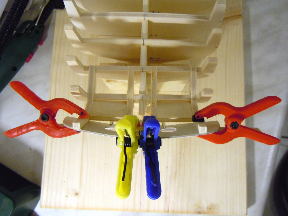
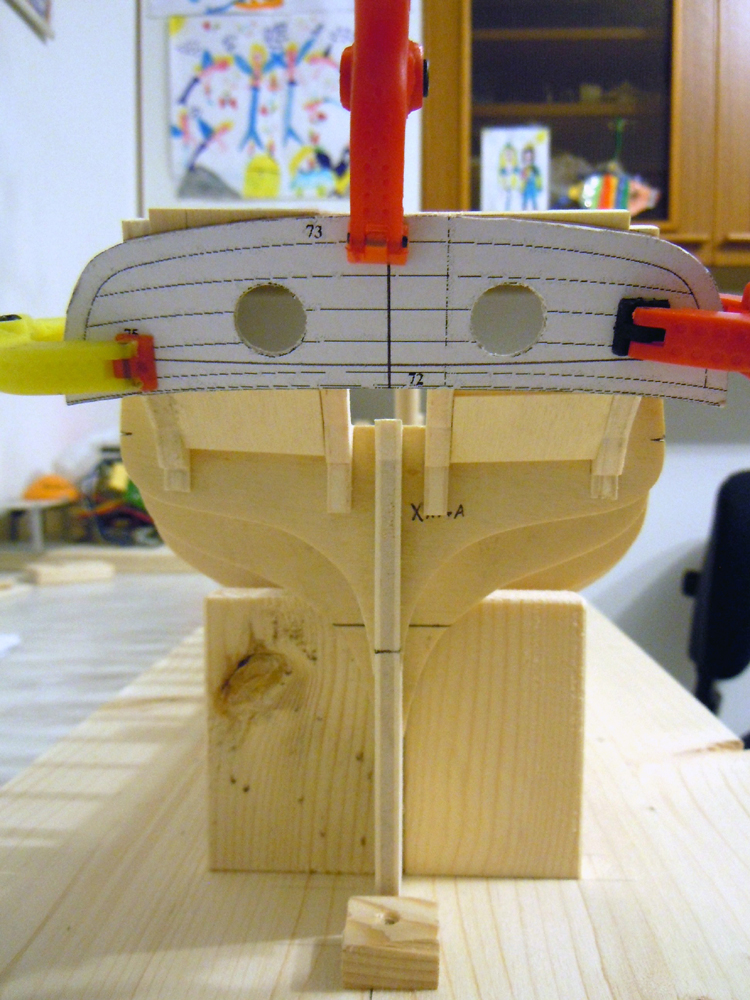
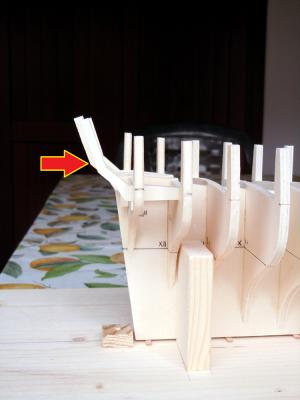
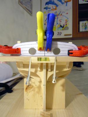
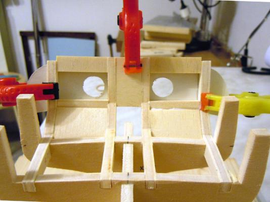
November 11th, 2014 Next task, as said above, was to strengthen the weak transom timbers in preparation for the bulkheads bevels sanding and to get an even surface ready to receive the transom piece. So the first thing was to prepare a cardboard template of the transom to check the proper shape and alignment of the transom timbers. The next picture shows these pieces from the side and permits to appreciate the slight offsets of the two side timbers w.r.t. the central timbers: - the vertical downward shift, about 2mm, is automatically obtained thanks to the curvature of the bulkheads’ upper profile (i.e. of the deck) where the transom timbers are fixed. - the horizontal offset is obtained by shifting the side timbers forward by 4mm (related to the fore&aft position of the central timbers and aftermost bulkhead n.XIII). Given the aft slope of the transom above the knee (pointed to by the red arrow), this horizontal offset then reduces to about 3mm as an effect of the above mentioned vertical shift. The curvature of the transom can be better seen in the following picture, where the transom template is test fit. And here is how I checked the proper alignment of the transom timbers: the building base is set perfectly horizontal (as much as possible with the tools I own ), the verticality of the keel is adjusted (square angle to the base board), a reference horizontal line is drawn on the transom template and checked with a spirit level. After the transom is correctly positioned and oriented (horizontally, vertically and side inclination), its position is marked on the transom timbers as a reference. In particular, the lower border of the transom is checked to lay along the alignment of knees of the transom timbers (minor adjustments to these was required). With all these checks done, the two circular holes in the transom are perfectly located with respect to the transom timbers: now it is possible to install the joining pieces that strengthen the latter and create the base for the shape of the transom itself. Alignment of these pieces is not important, provided that the area surrounding the circles is left free for a filler piece on more ‘noble’ wood (this area will be visible, so plywood is forbidden!!). The last picture shows the area where the lower counter will be installed, below the transom. Another cardboard template is needed for the counter, to check the correct shape of the transom timbers below the knee where it is located. This will be my next task, together with the addition of other reinforcements outside of the side transom timbers and with the bow filler pieces. All these check and verification activities will be alternated by the cut and gluing of the pieces in-between each couple of bulkheads, creating a strong and stiff structure for the hull. Stay tuned! FAM


-
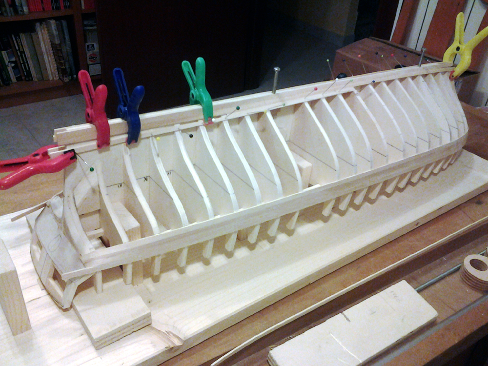
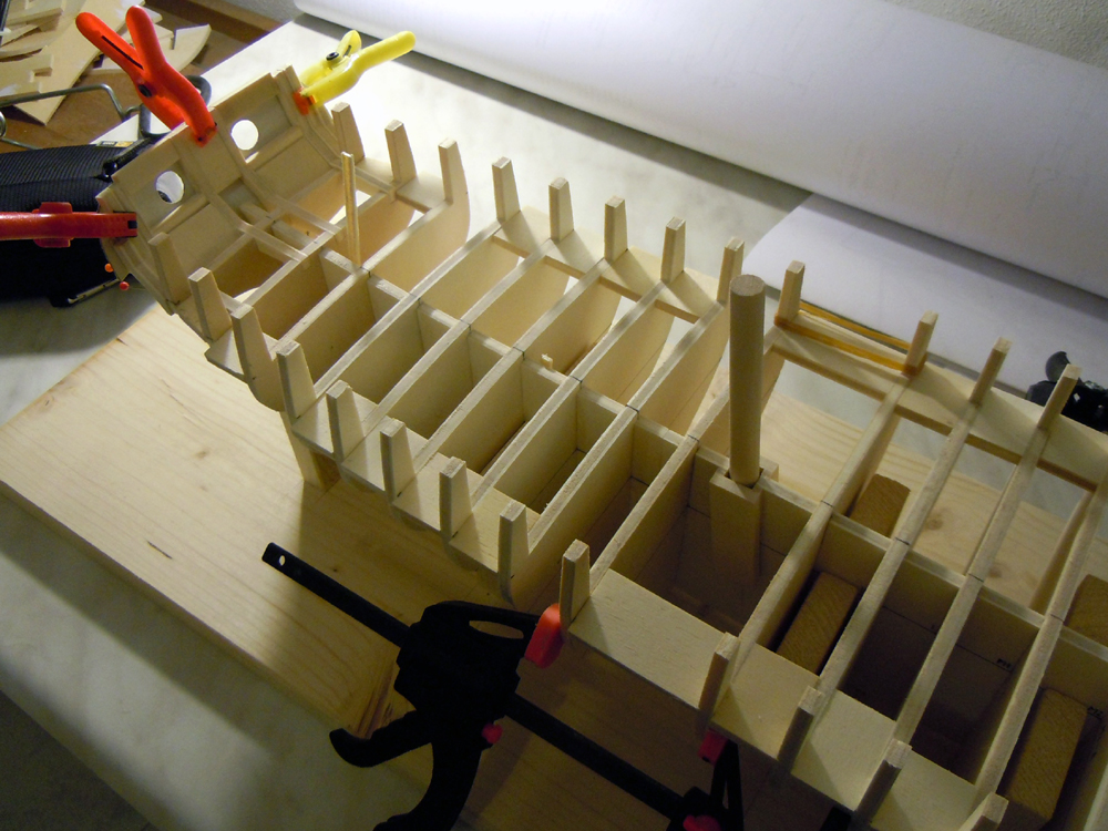
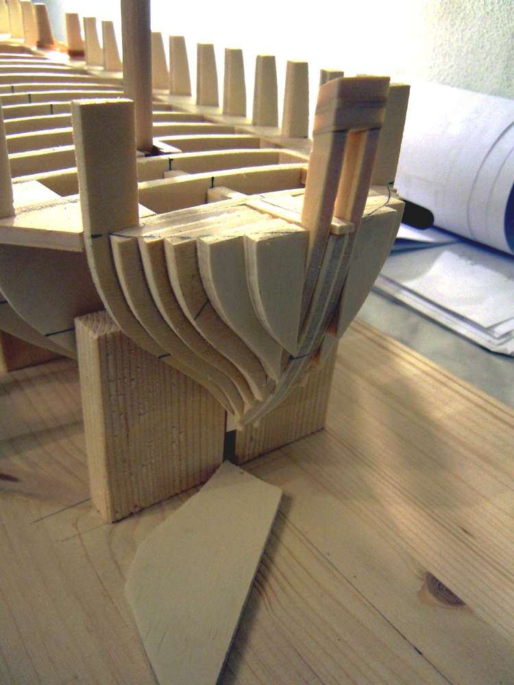
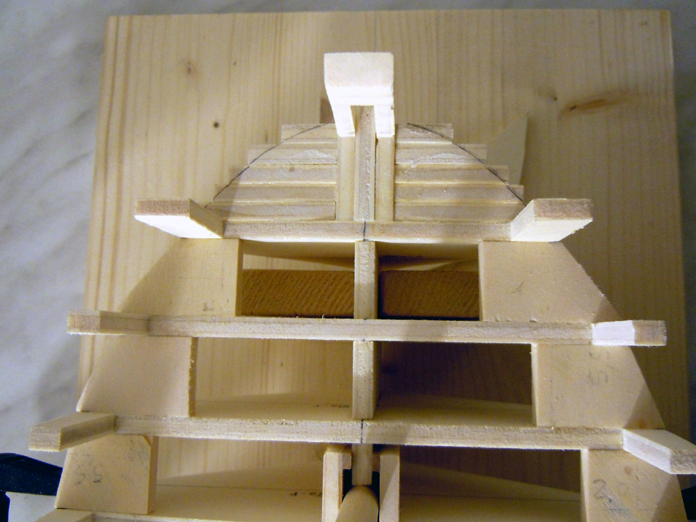
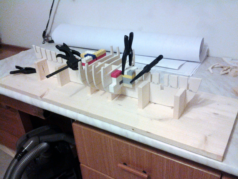
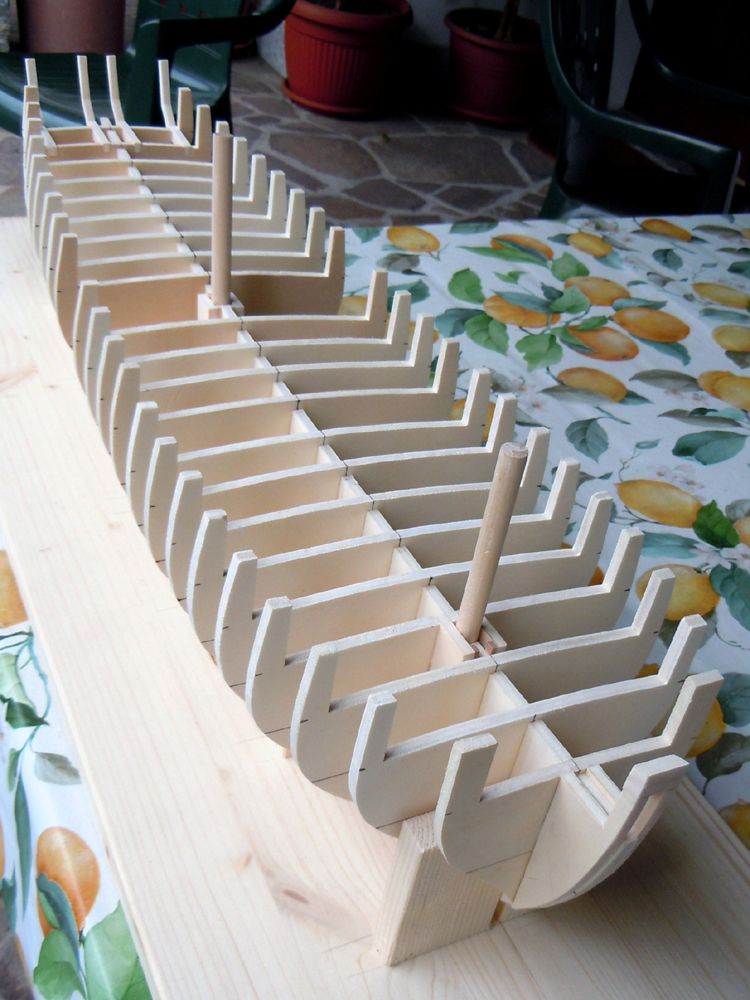
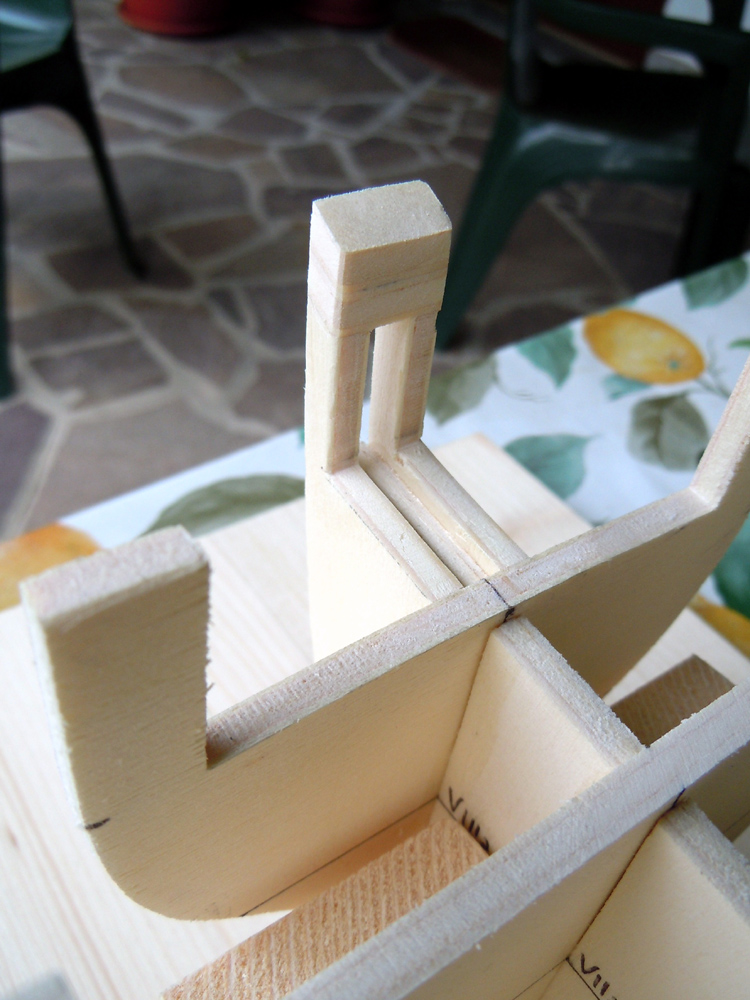
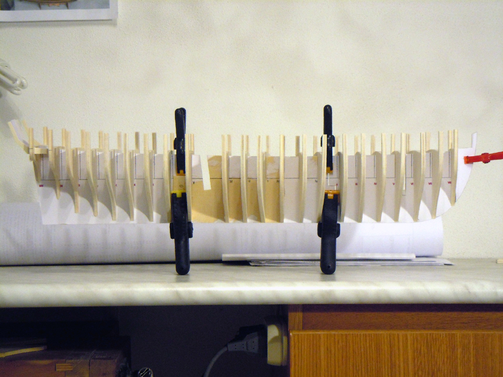
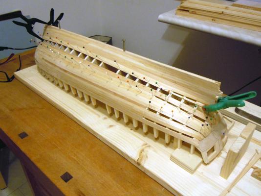
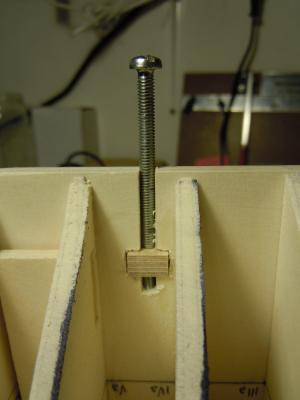
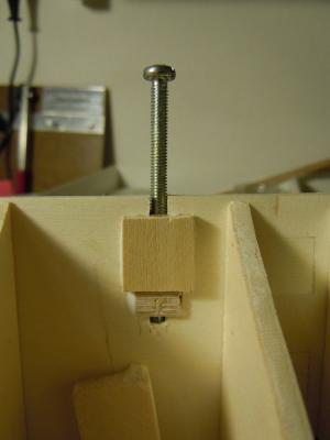
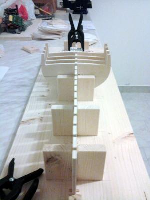
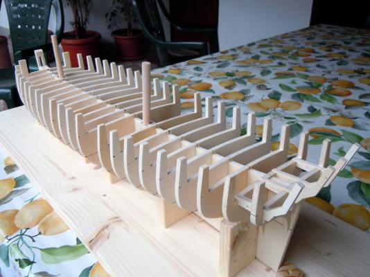
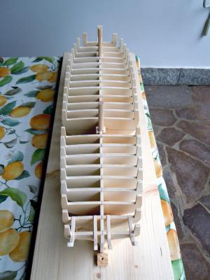
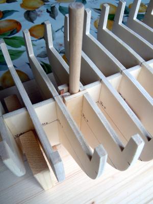
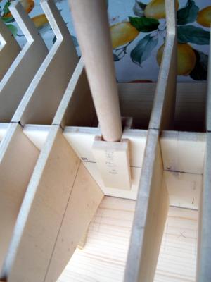
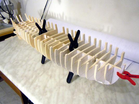
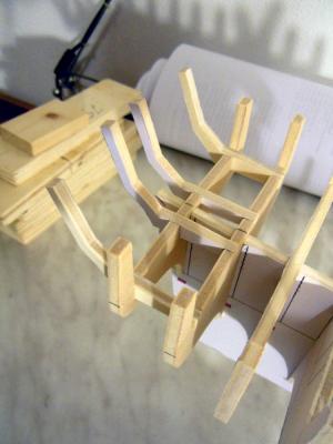
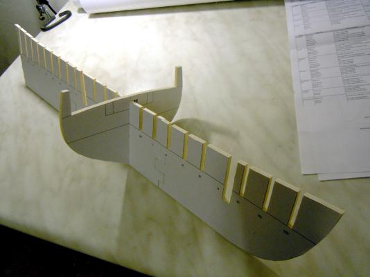
November 06th, 2014 Let’s go on... I spent some days in collecting all the parts to build the base-board. The copyright of its layout is 100% of JA: it works, so why not copying?? Another friend of mine, in the Company I work for, kindly cut the upright posts with a large circular saw to ease my work. Then I quickly assembled all the parts and immediately started gluing the frames. Well... not so immediately, because each bulkhead needed cleaning from paper formers, filing and sanding the borders and finally fine trimming the joints slot with the keel. Anyway, the following pictures show the start of the gluing phase. I always had used LEGO blocks to ensure the bulkheads are correctly at a square angle to the keel, and this time was not different (thx to my son who lent me the pieces I needed !! ) November 09th, 2014 3 days later, the job is completed. This is a minor milestone in the project, for me, so I shot lot of pictures in good daylight (I usually work at night in artificial light). Here are three of these shots: can you see what I wrote about the shape of the hull being so evident thanks to the large number of bulkheads? I also tested the flow of the hull lines from bow to stern with a thin and long plank, and the result is really outstanding! No corrections to be done, perfect alignment of the frames and top-timbers: ready to start beveling the bulkheads before laying the planks. But many other works have to be completed before, to fix the inherent weakness of the stern timbers and give a proper shape to the transom and bow. Finally, I show the details of the masts steps and the bow timbers (maybe ‘hawse timber’ is more correct?) - For the mainmast step I sandwiched two battens of the required thickness (2.5mm) between the keel and another piece of plywood, so that the width of the housing is exactly 10mm (that is the diameter of the mainmast according to Lees, the reference we decided to use preliminarly). This creates a squared housing 10x10mm, 50mm deep, where the dummy dowel for the mainmast fits tightly. - For the foremast step I used the same concept, but the side plywood pieces are directly notched into bulkhead n. Va for a stronger joint. In this case the size of the housing is 9x9mm, again 50mm deep. - To conclude, I’ve joined the top parts of the two bow fillers, representing something similar to the innermost hawse timbers, with horizontal plywood pieces: they have been glued in position and then suitably shaped. This fixes an error I did in interpretation of the required height for these parts. I still have to check this height with the top timbers of the bulkheads, but this is an easy job. Here it is also evident that I already cut the toptimbers of the foremost bulkhead (n. VIIIa) with double width, to account for the subsequent beveling. That’s all for today FAM


-
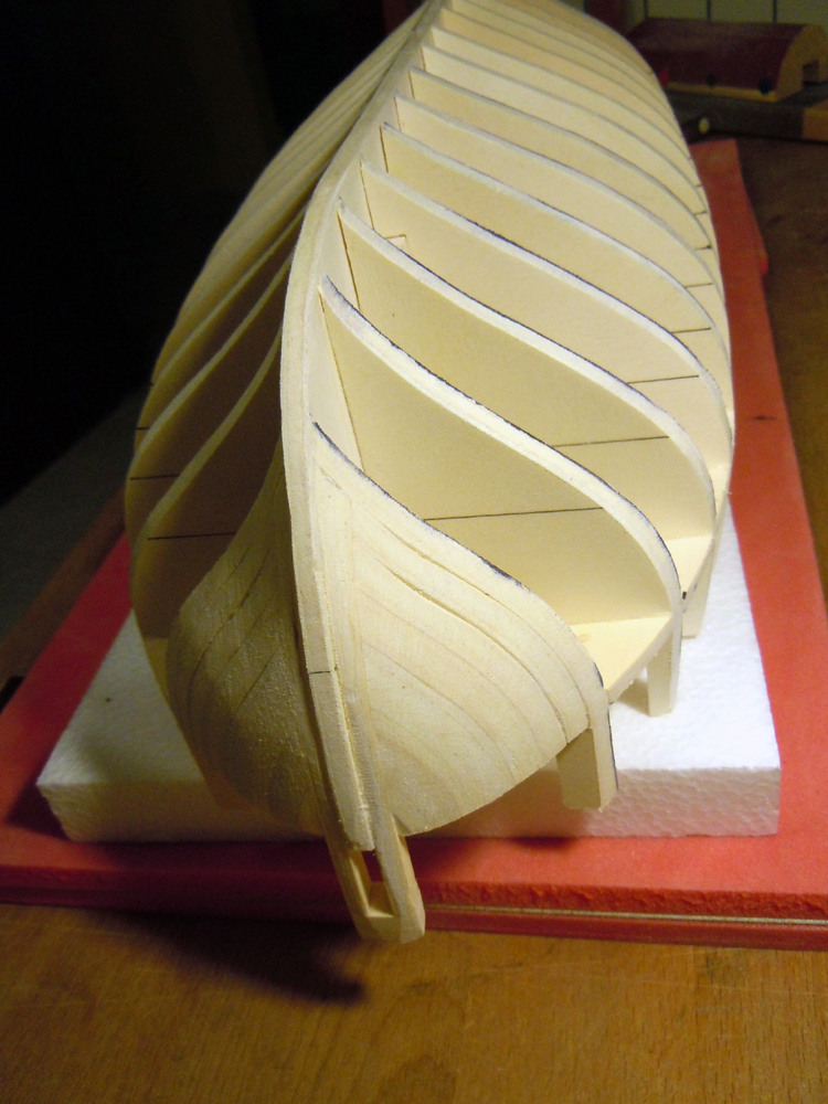
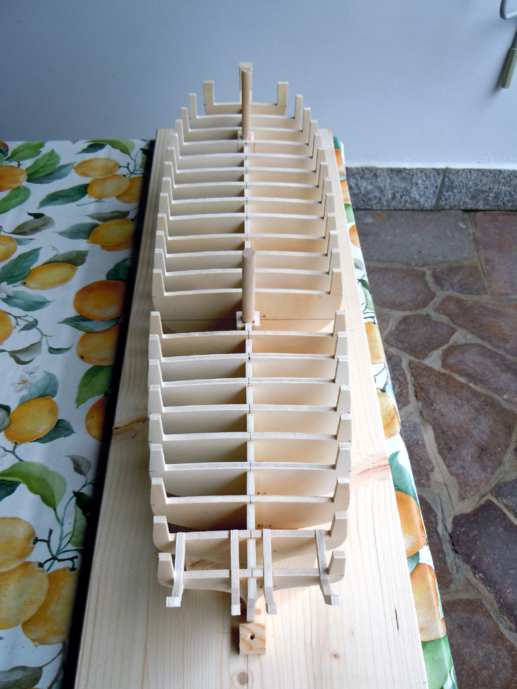
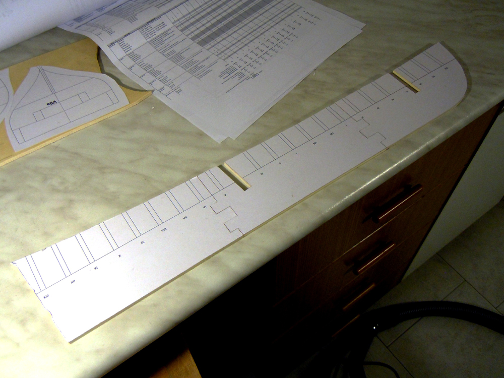
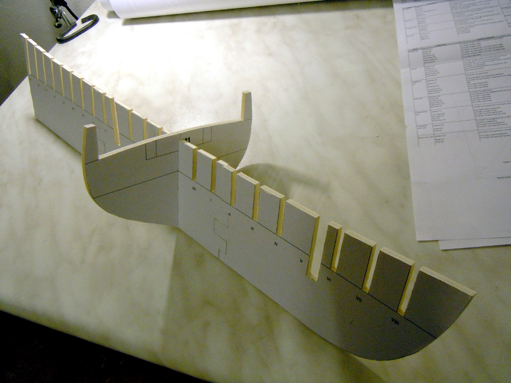
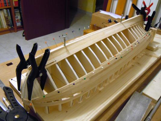
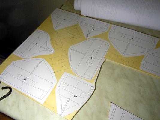
November 01st, 2014 A few days later, this is how she looked. I logged about 15 hours to get at this stage: all the bulkheads cut, the false keel cut, the bow fillers and transom timbers cut, all the parts finished, checked and dry fitted. Some detail about my technique: I used 5mm thick poplar plywood, so had to use a dedicated version of the plans that JA kindly provided. All the parts are hand-cut with a manual scroll-saw, as I’ve little room in my 3x3m workshop for bulky tools and machines (that will remain, anyway, my dream ). The bulkheads are cut for a tight fitting with the false keel, considering that the paper formers still have to be peeled away. I used a stick glue for the formers, that is quite easy to remove but strong enough to support the stress of the saw blade. The attentive observers could note that something is different from JA’s model: - the most evident is the number of bulkheads. While JA decided to reduce it to the minimum strictly required for the building, I retained all the original 22 bulkheads that he had draught. The only missing is the #5, corresponding to the main mast slot. Even for the foremast slot, I managed to arrange a solution that uses the bulkhead itself as one of the side walls for the mast slot. Reason for this? No real need, call it a personal fixation, or whatever you prefer: I like seeing the shape of the hull coming out from the very beginning. Even with my Pinco I used the same approach and doubled the number of bulkheads w.r.t. those required by Euromodel plans. - Another evident difference is the fact that I didn’t use the two longitudinal beams, as I deemed them not necessary if the stiffeners between the bulkheads are used (that is my program). - A third thing is that I did not use the joints strengtheners for the 3 keel pieces: again, to me these are unnecessary pieces because the building base holds the keel firmly and straight aligned until all the stiffeners are installed. Well, same direction, slightly different paths... When I had arrived at this stage, JA warned me that his plans contained two minor but significant errors: the first dealt with the stations of the bulkheads along the keel, and instead of trying to fix it I resolved the problem by cutting 3 new pieces for the entire false keel. The second error dealt with the height of the deck with respect to the top of the bulwark (is this the name?) toptimbers. As JA better explained in his build-log, the error was due to a misinterpretation of a drawing not in the correct scale. Too late for him, in time for me (thx JA!!). I recalculated the correct height of the deck, considering the thickness of the false-deck and deck planks I intended to use, and then I only had to remove 0.8-1mm from the top profile of each bulkhead. Easily done with the scroll saw. The last difference for today is the way I arranged the transom timbers (hope this is the correct name): I joined them to the last and last-but-one bulkheads, to get a stronger joint. This will be a weak point of the structure until they will be joined by other pieces, which will be my next task. (BTW, can you see how I moved 2.5mm aft the bulwarks without changing the original CAD plans?) The transom timbers are shaped so that they form a curved line when seen from above and from behind, matching the transom shape on the plans (will be seen later). That’s all for today Ciao a tutti FAM

-
Hi all this is the opening of my shipyard for building this little ship. Well... maybe little in the real world, because due to the scale the complete model will be longer than 1 meter, so quite huge for normal standards (I mean the standard size of Italian houses). An explanation about the title of this topic: ‘Brick de 24’ is the name of a class of ships, brigs type, whose main weapons were 24pdr carronades, in the number of 14. Other weapons were two 6pdr long guns. They were designed (most of them) by the master designer Pestel and built between 1806 and 1813. Many more information can be read here: http://modelshipworld.com/index.php/topic/7795-brick-de-24-by-jackaubrey-148-scale/#entry231121 in the topic of my good friend, and co-builder, Jack Aubrey. The ship plans are available in the excellent monography “Le Cygne” issued by Ancre, including 19 sheets of 1:48 scale detailed drawings and plans. This will be a joint construction: JA started before, and completed the most difficult job of transferring the Ancre plans to AutoCAD. I assisted at the starting of his project and was really impressed by the beauty of this ship: I already had lot of pictures of Le Cygne and Le Cyclope (another ship of the same class) in my database, and have always looked at them as a possibility for the future. So when JA started the possible future become the present, and I contacted him to ask if I could joint his project. So, before anything else, I have to say THANK YOU SO MUCH to my friend Sergio for allowing me to join him in the project and for providing me, for free, the CAD plans to start with my model. My copy of the monography has been shipped and is on the way, but unfortunately I’ll have to wait for it until the end of this month. As JA explained, we decided to build a different shipmodel with respect to those already existing, namely Le Cygne, Le Cyclope, Le Cureiux and L’Esperance. More, JA decided (or initially thought about) to show her after it was seized by the Royal Navy and re-commissioned for active service with the British, so with some modification to the original Ancre plans. I’ve not decided yet what to do, but I will probably stick to the French configuration making good use of the excellent Ancre plans. Which ship? We had a long discussion about this item, and I told Sergio that I will leave to him the priority of choice among the names that he elected as preferred. Therefore I will decide after him, but the rose of candidates is restricted among: - Le Nisus (1805), seized in 1809 (--> HMS Guadeloupe) - Le Milan (1806), seized in 1809 (--> HMS Achates) - Le Phaéton (1806), seized in 1806 (--> HMS Mignonne) - Le Colibri (1809), seized in 1809 (--> HMS Colibrì) The figurehead will be fictious, as no information exists for these ships, but obviously based on the name of the ship. I will find in internet some beautiful picture of that birds and do my best to get a decently carved figurehead. The model The size is quite large, according to Ancre website it will be 74cm long (the hull, 116cm fully rigged), 17cm wide (52cm rigged) and 17cm high (86cm tall fully rigged). The wood will be... ehm ... well, whatever I manage to find. I mean, it’s quite difficult here in Italy to find sources of good wood for modelling at acceptable prices. I have some pearwood available, some other is seasoning, will use poplar plywood for the hull structure, probably limewood for the deck, a reddish variant of pinewood for the bulwarks, yet don’t know what for the hull planking (well, the hull is coppered so probably it is not important). The model will be POB type. After this long presentation... October 19th, 2014 Grand opening of the shipyard, the first sawdust is produced... My best regards Fam

-
Thank you Jack, it was a pleasant noon for me, too! I'm sure I will enjoy the collaboration, as we have already done in the past, and the building of this new project. Today I've got the basic material for the hull structure and the building base, this evening will start to produce some sawdust See you soon Fam
-
Hi Jack interesting dilemma... Definitely, i.m.h.o., better a fake figurhead than a dummy or nothing at all! What about carving a fake figurhead based on the name you will chose for the ship? OK, not historically accurate, but apparently there are no other sources contributing to the solution of the problem. Lot of pictures are available in Google... Ciao Fam
-
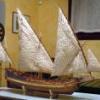
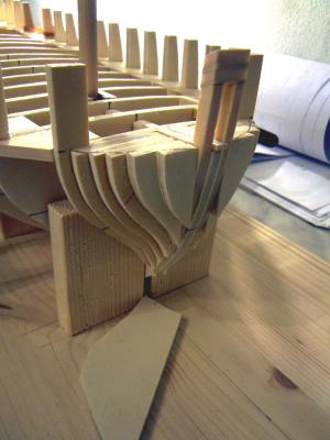
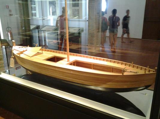
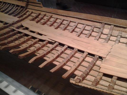
Hi all per description panels in the museum, the boat I showed above was part of a small flottille owned by Marco Vipsanio Agrippa, general, admiral of the sixth fleet and brother-in-law of Emperor Ottavianus Augustus. It has been dated to 12 b.C. thanks to several inscriptions found in the cargo. It was designed to sail along the sandy shores of the upper western Adriatic Sea and upstream the Po river, that's the reason for the flat bottom and shallow hull. It sunk during a storm (probably it was unsuitable to heavy sea conditions) and was almost immediatly covered with very fine sand and mud, that explains the perfect status of conservation of wood, vegetal fibers, leather and food found in the relict. It was descovered in 1981 during the maintenance works of the Valli di Comacchio channels (Valli di Comacchio is a preserved natural area with lot of swamps and channels, famous for the flamingos). Her name was 'Fortuna Marii'. The cargo was more than 200 amphors, containing oil, wine and wheat and several tenths of lead ingots (from Agrippa's property mines in Hibernia - Spain: Agrippa's name is carved on them) used as ship ballast, but intended to be sold along the river trip to be melted and reused for lead water plumbing. The hull is built with two techniques: below the waterline the planks were "sewn" to the frames with vegetal fibers ropes, and made waterproof with tar; above the waterline the tenon-pin technique was used to join the planks. All these parts have been found, are still present in the conserved relict but are not visible to the public because the relict is conserved into a bed of demineralized water, at constante temperature and protected from sun light. The building technique started from the keel laying, then the first planks (garboard?) were joined to the keel, the frames pieces added above the planks and sewn to them and to the keel. The frames were built at the same time as the planks were joined creating the shape of the hull, which is the opposite of the technique we are accustomed to. She had one mast and a squared sail (parts of it have been found!) and twin side rudders. There is an open cargo compartment and a sort of enclosed cabin for the crew (covered with cotto tiles). The anchors and several blocks were also found in situ. I have several pictures taken at the museum, should anyone be interested in. Here is the link to the city webpage, with some infos, directions and pictures: http://195.62.166.245/comacchio/common/AmvSezione.do?MVPD=0&MVSZ=42 Ciao Fam
-
Hi Dan are you meaning something like this? It's the reconstruction of a late roman trade ship (empire age, end of 1st century b.C.), the original is in quite good state of conservation in a dedicated museum in Comacchio city, close to Ferrara. The museum shows all what was found during the excavation of the relict, including the full load, the ballast, crew personal belongins, etc., and also shows a recostruction model of the whole ship and a recostruction model of the relict (that is not visitable by the public) with lot of fantastic details (see second picture). Regards Fam
-
Hi, I confirm what Nimbrook wrote: there is some re-engineering here and there, the most important is the double planking vs single. Also cannot exclude that some of the eached brass or castings have been modified, but basically it remains the same kit. DeA version was sold in weekly issues, with much more detailed instructions for beginners. It was my 1st kit and I was able to complete it in about 2800 hours and 4 years (I took my time!), including lot of improvements and modifications, so to me the DeA version is a medium difficulty. Regards Fam
-
Hi Mangaroca I built the DeA version and had the possibility to check the OcCre list of materials, instructions and building steps pictures: they are basically the same kit, but DeA provided much more detailed step-by-step instructions. Don't know if it is still the same nowaday. No idea about the OcCre materials quality. Regards Fam
-
A question on working mizzen lateen sails
Fam replied to Stevinne's topic in Masting, rigging and sails
Hi all may I show you this: Hope this helps. Ciao Fam